EP0576662B1 - Intimate source and detector and apparatus employing same - Google Patents
Intimate source and detector and apparatus employing same Download PDFInfo
- Publication number
- EP0576662B1 EP0576662B1 EP93903449A EP93903449A EP0576662B1 EP 0576662 B1 EP0576662 B1 EP 0576662B1 EP 93903449 A EP93903449 A EP 93903449A EP 93903449 A EP93903449 A EP 93903449A EP 0576662 B1 EP0576662 B1 EP 0576662B1
- Authority
- EP
- European Patent Office
- Prior art keywords
- light
- field
- target
- light source
- assembly according
- Prior art date
- Legal status (The legal status is an assumption and is not a legal conclusion. Google has not performed a legal analysis and makes no representation as to the accuracy of the status listed.)
- Expired - Lifetime
Links
Images

Classifications
-
- G—PHYSICS
- G06—COMPUTING; CALCULATING OR COUNTING
- G06K—GRAPHICAL DATA READING; PRESENTATION OF DATA; RECORD CARRIERS; HANDLING RECORD CARRIERS
- G06K7/00—Methods or arrangements for sensing record carriers, e.g. for reading patterns
- G06K7/10—Methods or arrangements for sensing record carriers, e.g. for reading patterns by electromagnetic radiation, e.g. optical sensing; by corpuscular radiation
- G06K7/10544—Methods or arrangements for sensing record carriers, e.g. for reading patterns by electromagnetic radiation, e.g. optical sensing; by corpuscular radiation by scanning of the records by radiation in the optical part of the electromagnetic spectrum
- G06K7/10554—Moving beam scanning
- G06K7/10594—Beam path
- G06K7/10683—Arrangement of fixed elements
- G06K7/10702—Particularities of propagating elements, e.g. lenses, mirrors
-
- G—PHYSICS
- G06—COMPUTING; CALCULATING OR COUNTING
- G06K—GRAPHICAL DATA READING; PRESENTATION OF DATA; RECORD CARRIERS; HANDLING RECORD CARRIERS
- G06K7/00—Methods or arrangements for sensing record carriers, e.g. for reading patterns
- G06K7/10—Methods or arrangements for sensing record carriers, e.g. for reading patterns by electromagnetic radiation, e.g. optical sensing; by corpuscular radiation
- G06K7/10544—Methods or arrangements for sensing record carriers, e.g. for reading patterns by electromagnetic radiation, e.g. optical sensing; by corpuscular radiation by scanning of the records by radiation in the optical part of the electromagnetic spectrum
- G06K7/10554—Moving beam scanning
- G06K7/10594—Beam path
Abstract
Description
Claims (14)
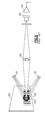
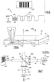
- An optical assembly for use in detecting indicia, comprising :characterized in that it further comprises :a light source means (26, 426) for emitting a first beam of light (36, 436) that is incident on a field of illumination of a target (12, 412), said target being located in a working depth of field (21) ;a light sensor means (24, 424) for producing a signal in response to light carried in said first beam to said target and returning from a region of sensitivity thereon, said returning light being carried in a second beam of light (38, 438) that extends from said target to said light sensor means ;optical means (14, 414) disposed in said first beam of light and in said second beam of light for forming an image of said light source means on said target;means (20, 420) for configuring said light source means to a sectional area and shape at said target that are identical to a sectional area and shape of said image of said light sensor means at said target;and in that :means (22, 422) for dimensioning at least one of said first beam and said second beam such that said first beam and said second beam are precisely superimposed between said target and said optical means ;and means for excluding unwanted light from said light sensor means ;said optical means (14, 414) are forming a back-projection of said region of sensitivity on said light sensor means (24, 424), said back -projection being transmitted in said second beam, said first beam and said second beam following a common path between said optical means and said target;and said field of illumination precisely coincides with said region of sensitivity in any plane throughout said working depth of field.
- The assembly according to claim 1, characterized in that said means for configuring comprises :a first field stop means (20, 420) proximate said light source means ;and a second field stop means (22, 422) proximate said light sensor means.
- The assembly according to claim 1, characterized in that said optical means comprises :beam splitter means (15, 415) for directing a portion of said returning light to said light sensor means, and for directing a portion of light emitted from said light source means to said target; anda lens means (14).
- The assembly according to claim 3, characterized in that said lens means comprises :a first lens (514), disposed between said beam splitter means (415) and said light source means (426) ; anda second lens (414), disposed between said beam splitter means (415) and said light sensor means (424).
- The assembly according to claim 3, characterized in that said lens means comprises a single lens (14), disposed between said beam splitter means (15) and said target (12).
- The assembly according to claim 1, characterized in that said means for configuring consists of first field stop means (20, 420) being integral with said light source means (26, 426).
- The assembly according to claim 1, characterized in that said means for dimensioning consists of second field stop means (22, 422) is integral with said light sensor means (24, 424).
- The assembly according to claim 1, characterized in that said means for configuring and dimensioning consist of first (20,420) and second (22, 422) field stop means comprising circular field stops.
- The assembly according to claim 1, characterized in that said means for configuring and dimensioning consist of first (20, 420) and second (22, 422) field stop means comprising elliptical field stops.
- The assembly according to claim 1, characterized in that said means for configuring and dimensioning consist of first (20, 420) and second (22, 422) field stop means comprising polygonal field
- The assembly according to claim 1, characterized in that said means for configuring and dimensioning consist of first (20, 420) and second (22, 422) field stop means comprising rectangular field stops.
- The assembly according to claim 1, characterized in that said means (22, 422) for dimensioning comprises a lens aperture.
- The assembly according to claim 1, characterized in that said light sensor means is selected from the group of photo diode, avalanche photo diode, photo multiplier, photo transistor and photo-FET.
- The assembly of claim 1, characterized in that said light source means is selected from the group of LED, laser, incandescent lamp and arc lamp.
Applications Claiming Priority (3)
| Application Number | Priority Date | Filing Date | Title |
|---|---|---|---|
| US82248492A | 1992-01-17 | 1992-01-17 | |
| US822484 | 1992-01-17 | ||
| PCT/US1993/000283 WO1993014471A1 (en) | 1992-01-17 | 1993-01-13 | Intimate source and detector and apparatus employing same |
Publications (2)
| Publication Number | Publication Date |
|---|---|
| EP0576662A1 EP0576662A1 (en) | 1994-01-05 |
| EP0576662B1 true EP0576662B1 (en) | 1998-06-17 |
Family
ID=25236156
Family Applications (1)
| Application Number | Title | Priority Date | Filing Date |
|---|---|---|---|
| EP93903449A Expired - Lifetime EP0576662B1 (en) | 1992-01-17 | 1993-01-13 | Intimate source and detector and apparatus employing same |
Country Status (5)
| Country | Link |
|---|---|
| US (1) | US5430286A (en) |
| EP (1) | EP0576662B1 (en) |
| JP (1) | JPH06506788A (en) |
| DE (1) | DE69319185D1 (en) |
| WO (1) | WO1993014471A1 (en) |
Families Citing this family (42)
| Publication number | Priority date | Publication date | Assignee | Title |
|---|---|---|---|---|
| US6631842B1 (en) | 2000-06-07 | 2003-10-14 | Metrologic Instruments, Inc. | Method of and system for producing images of objects using planar laser illumination beams and image detection arrays |
| US7387253B1 (en) | 1996-09-03 | 2008-06-17 | Hand Held Products, Inc. | Optical reader system comprising local host processor and optical reader |
| US5560291A (en) * | 1995-09-20 | 1996-10-01 | Shu; Ming Fang | Stamping machine |
| US6629641B2 (en) | 2000-06-07 | 2003-10-07 | Metrologic Instruments, Inc. | Method of and system for producing images of objects using planar laser illumination beams and image detection arrays |
| US5859418A (en) * | 1996-01-25 | 1999-01-12 | Symbol Technologies, Inc. | CCD-based bar code scanner with optical funnel |
| US7304670B1 (en) * | 1997-03-28 | 2007-12-04 | Hand Held Products, Inc. | Method and apparatus for compensating for fixed pattern noise in an imaging system |
| US6435411B1 (en) | 1997-04-21 | 2002-08-20 | Intermec Ip Corp. | Optoelectronic device for acquisition of images, in particular of bar codes |
| US7028899B2 (en) | 1999-06-07 | 2006-04-18 | Metrologic Instruments, Inc. | Method of speckle-noise pattern reduction and apparatus therefore based on reducing the temporal-coherence of the planar laser illumination beam before it illuminates the target object by applying temporal phase modulation techniques during the transmission of the plib towards the target |
| US7584893B2 (en) | 1998-03-24 | 2009-09-08 | Metrologic Instruments, Inc. | Tunnel-type digital imaging system for use within retail shopping environments such as supermarkets |
| US6269169B1 (en) * | 1998-07-17 | 2001-07-31 | Imaging Automation, Inc. | Secure document reader and method therefor |
| US6366707B1 (en) * | 1999-04-13 | 2002-04-02 | Hewlett-Packard Company | Imaging apparatus alignment system and method |
| US6959870B2 (en) | 1999-06-07 | 2005-11-01 | Metrologic Instruments, Inc. | Planar LED-based illumination array (PLIA) chips |
| US7270274B2 (en) | 1999-10-04 | 2007-09-18 | Hand Held Products, Inc. | Imaging module comprising support post for optical reader |
| US6912076B2 (en) | 2000-03-17 | 2005-06-28 | Accu-Sort Systems, Inc. | Coplanar camera scanning system |
| US7607581B2 (en) | 2003-11-13 | 2009-10-27 | Metrologic Instruments, Inc. | Digital imaging-based code symbol reading system permitting modification of system features and functionalities |
| US7540424B2 (en) | 2000-11-24 | 2009-06-02 | Metrologic Instruments, Inc. | Compact bar code symbol reading system employing a complex of coplanar illumination and imaging stations for omni-directional imaging of objects within a 3D imaging volume |
| US8042740B2 (en) | 2000-11-24 | 2011-10-25 | Metrologic Instruments, Inc. | Method of reading bar code symbols on objects at a point-of-sale station by passing said objects through a complex of stationary coplanar illumination and imaging planes projected into a 3D imaging volume |
| US7464877B2 (en) | 2003-11-13 | 2008-12-16 | Metrologic Instruments, Inc. | Digital imaging-based bar code symbol reading system employing image cropping pattern generator and automatic cropped image processor |
| US7128266B2 (en) | 2003-11-13 | 2006-10-31 | Metrologic Instruments. Inc. | Hand-supportable digital imaging-based bar code symbol reader supporting narrow-area and wide-area modes of illumination and image capture |
| US7594609B2 (en) | 2003-11-13 | 2009-09-29 | Metrologic Instruments, Inc. | Automatic digital video image capture and processing system supporting image-processing based code symbol reading during a pass-through mode of system operation at a retail point of sale (POS) station |
| US7490774B2 (en) | 2003-11-13 | 2009-02-17 | Metrologic Instruments, Inc. | Hand-supportable imaging based bar code symbol reader employing automatic light exposure measurement and illumination control subsystem integrated therein |
| US7708205B2 (en) | 2003-11-13 | 2010-05-04 | Metrologic Instruments, Inc. | Digital image capture and processing system employing multi-layer software-based system architecture permitting modification and/or extension of system features and functions by way of third party code plug-ins |
| US7954719B2 (en) | 2000-11-24 | 2011-06-07 | Metrologic Instruments, Inc. | Tunnel-type digital imaging-based self-checkout system for use in retail point-of-sale environments |
| US7270273B2 (en) | 2001-01-22 | 2007-09-18 | Hand Held Products, Inc. | Optical reader having partial frame operating mode |
| EP2249284B1 (en) | 2001-01-22 | 2014-03-05 | Hand Held Products, Inc. | Optical reader having partial frame operating mode |
| US7268924B2 (en) | 2001-01-22 | 2007-09-11 | Hand Held Products, Inc. | Optical reader having reduced parameter determination delay |
| US7331523B2 (en) | 2001-07-13 | 2008-02-19 | Hand Held Products, Inc. | Adaptive optical image reader |
| US7513428B2 (en) | 2001-11-21 | 2009-04-07 | Metrologic Instruments, Inc. | Planar laser illumination and imaging device employing laser current modulation to generate spectral components and reduce temporal coherence of laser beam, so as to achieve a reduction in speckle-pattern noise during time-averaged detection of images of objects illuminated thereby during imaging operations |
| US7055747B2 (en) | 2002-06-11 | 2006-06-06 | Hand Held Products, Inc. | Long range optical reader |
| US7219843B2 (en) * | 2002-06-04 | 2007-05-22 | Hand Held Products, Inc. | Optical reader having a plurality of imaging modules |
| US20030222147A1 (en) | 2002-06-04 | 2003-12-04 | Hand Held Products, Inc. | Optical reader having a plurality of imaging modules |
| US7090132B2 (en) * | 2002-06-11 | 2006-08-15 | Hand Held Products, Inc. | Long range optical reader |
| US8596542B2 (en) | 2002-06-04 | 2013-12-03 | Hand Held Products, Inc. | Apparatus operative for capture of image data |
| US7841533B2 (en) | 2003-11-13 | 2010-11-30 | Metrologic Instruments, Inc. | Method of capturing and processing digital images of an object within the field of view (FOV) of a hand-supportable digitial image capture and processing system |
| US7017812B1 (en) * | 2003-11-26 | 2006-03-28 | The United States Of America As Represented By The Administrator Of The National Aeronautics And Space Administration | Variable distance angular symbology reader |
| US7852519B2 (en) | 2007-02-05 | 2010-12-14 | Hand Held Products, Inc. | Dual-tasking decoder for improved symbol reading |
| US8628015B2 (en) | 2008-10-31 | 2014-01-14 | Hand Held Products, Inc. | Indicia reading terminal including frame quality evaluation processing |
| US8587595B2 (en) | 2009-10-01 | 2013-11-19 | Hand Held Products, Inc. | Low power multi-core decoder system and method |
| EP3089072B1 (en) | 2010-03-11 | 2018-09-12 | Datalogic IP TECH S.r.l. | Image capturing device |
| US8561903B2 (en) | 2011-01-31 | 2013-10-22 | Hand Held Products, Inc. | System operative to adaptively select an image sensor for decodable indicia reading |
| US8608071B2 (en) | 2011-10-17 | 2013-12-17 | Honeywell Scanning And Mobility | Optical indicia reading terminal with two image sensors |
| DK2780866T3 (en) * | 2011-11-15 | 2021-11-15 | Nestle Sa | CARRIER AND Capsule FOR PREPARING A BEVERAGE BY CENTRIFUGATION, SYSTEM AND PROCEDURE FOR PREPARING A BEVERAGE BY CENTRIFUGATION |
Family Cites Families (13)
| Publication number | Priority date | Publication date | Assignee | Title |
|---|---|---|---|---|
| US3744026A (en) * | 1970-06-10 | 1973-07-03 | Identicon Corp | Optical label scanning |
| NL181693C (en) * | 1974-11-29 | 1987-10-01 | Philips Nv | DEVICE FOR READING A RADIUS-REFLECTING REGISTRATION CARRIER BY OPTICAL ROAD. |
| US4143809A (en) * | 1977-10-11 | 1979-03-13 | Hewlett-Packard Company | Optical bar code reader |
| US4201910A (en) * | 1978-03-27 | 1980-05-06 | Innovation Industries, Inc. | Photosensor assembly |
| JPS54147035A (en) * | 1978-05-10 | 1979-11-16 | Minolta Camera Co Ltd | Tessar type photographic lens placed behind aperture |
| FR2479511A1 (en) * | 1980-03-25 | 1981-10-02 | Rao | Optical bar code reader using narrow slit illumination - uses condenser lenses and narrow slits allowing side by side dual scanners to check each other |
| US4346292A (en) * | 1981-02-02 | 1982-08-24 | International Business Machines Corporation | Coaxial optical scanner |
| JPS57152074A (en) * | 1981-03-16 | 1982-09-20 | Nippon Denso Co Ltd | Bar code reader |
| DE3242219C1 (en) * | 1982-11-15 | 1984-02-16 | Erwin Sick Gmbh Optik-Elektronik, 7808 Waldkirch | Optical brand recognition device |
| US4675531A (en) * | 1985-03-28 | 1987-06-23 | Polaroid Corporation | Optical scanner having a multi-surfaced lens arrangement for producing a rotationally symmetric beam |
| JP2608893B2 (en) * | 1987-07-10 | 1997-05-14 | 松下電器産業株式会社 | Optical pattern detector |
| US4816659A (en) * | 1987-10-13 | 1989-03-28 | Control Module Inc. | Bar code reader head |
| EP0524349A1 (en) * | 1991-07-08 | 1993-01-27 | Opticon Sensors Europe B.V. | Dual-focus scanner and such a scanner used as wandtype symbol code reader |
-
1993
- 1993-01-13 WO PCT/US1993/000283 patent/WO1993014471A1/en active IP Right Grant
- 1993-01-13 EP EP93903449A patent/EP0576662B1/en not_active Expired - Lifetime
- 1993-01-13 DE DE69319185T patent/DE69319185D1/en not_active Expired - Lifetime
- 1993-01-13 JP JP5512637A patent/JPH06506788A/en active Pending
-
1994
- 1994-02-25 US US08/202,669 patent/US5430286A/en not_active Expired - Lifetime
Also Published As
| Publication number | Publication date |
|---|---|
| US5430286A (en) | 1995-07-04 |
| WO1993014471A1 (en) | 1993-07-22 |
| EP0576662A1 (en) | 1994-01-05 |
| JPH06506788A (en) | 1994-07-28 |
| DE69319185D1 (en) | 1998-07-23 |
Similar Documents
| Publication | Publication Date | Title |
|---|---|---|
| EP0576662B1 (en) | Intimate source and detector and apparatus employing same | |
| EP0610504B1 (en) | Information reading apparatus | |
| US5319182A (en) | Integrated solid state light emitting and detecting array and apparatus employing said array | |
| US4682016A (en) | Pen-type bar code reader | |
| JP4805885B2 (en) | Lift detection suitable for navigation on transparent structures | |
| JP2772521B2 (en) | Optical system of floodlight-type photodetector | |
| US4753498A (en) | Optical reader | |
| KR100374244B1 (en) | Optical Device | |
| US11852852B2 (en) | Patterned mirror edge for stray beam and interference mitigation | |
| JP2002251259A (en) | Touch panel device | |
| US11886649B2 (en) | Optical navigation device | |
| US20020104888A1 (en) | Systems and methods for an encoded information reader | |
| JP3180019B2 (en) | Document edge detection device | |
| KR920002927B1 (en) | Portable laser scanner head frames optical system | |
| JP2776715B2 (en) | Optical reader | |
| JPH08161471A (en) | Detector for rugged pattern on surface of object | |
| JPH0526725A (en) | Limited reflection type sensor | |
| RU2179304C2 (en) | Photoregister of moving mark | |
| KR200190808Y1 (en) | Optical encoder | |
| JPH0668755A (en) | Light sensor | |
| JPH01227001A (en) | Detecting apparatus of position | |
| JP3578602B2 (en) | Document detection device | |
| JPH0567418A (en) | Optical sensor | |
| JPH09129916A (en) | Optical sensor | |
| JPH0469528A (en) | Area-limited reflection type photoelectric sensor |
Legal Events
| Date | Code | Title | Description |
|---|---|---|---|
| PUAI | Public reference made under article 153(3) epc to a published international application that has entered the european phase |
Free format text: ORIGINAL CODE: 0009012 |
|
| AK | Designated contracting states |
Kind code of ref document: A1 Designated state(s): BE DE FR GB IT LU NL |
|
| 17P | Request for examination filed |
Effective date: 19940105 |
|
| 17Q | First examination report despatched |
Effective date: 19960627 |
|
| GRAG | Despatch of communication of intention to grant |
Free format text: ORIGINAL CODE: EPIDOS AGRA |
|
| GRAG | Despatch of communication of intention to grant |
Free format text: ORIGINAL CODE: EPIDOS AGRA |
|
| GRAH | Despatch of communication of intention to grant a patent |
Free format text: ORIGINAL CODE: EPIDOS IGRA |
|
| GRAH | Despatch of communication of intention to grant a patent |
Free format text: ORIGINAL CODE: EPIDOS IGRA |
|
| GRAH | Despatch of communication of intention to grant a patent |
Free format text: ORIGINAL CODE: EPIDOS IGRA |
|
| GRAH | Despatch of communication of intention to grant a patent |
Free format text: ORIGINAL CODE: EPIDOS IGRA |
|
| GRAA | (expected) grant |
Free format text: ORIGINAL CODE: 0009210 |
|
| AK | Designated contracting states |
Kind code of ref document: B1 Designated state(s): BE DE FR GB IT LU NL |
|
| PG25 | Lapsed in a contracting state [announced via postgrant information from national office to epo] |
Ref country code: NL Free format text: LAPSE BECAUSE OF FAILURE TO SUBMIT A TRANSLATION OF THE DESCRIPTION OR TO PAY THE FEE WITHIN THE PRESCRIBED TIME-LIMIT Effective date: 19980617 Ref country code: IT Free format text: LAPSE BECAUSE OF FAILURE TO SUBMIT A TRANSLATION OF THE DESCRIPTION OR TO PAY THE FEE WITHIN THE PRE;WARNING: LAPSES OF ITALIAN PATENTS WITH EFFECTIVE DATE BEFORE 2007 MAY HAVE OCCURRED AT ANY TIME BEFORE 2007. THE CORRECT EFFECTIVE DATE MAY BE DIFFERENT FROM THE ONE RECORDED.SCRIBED TIME-LIMIT Effective date: 19980617 Ref country code: BE Free format text: LAPSE BECAUSE OF FAILURE TO SUBMIT A TRANSLATION OF THE DESCRIPTION OR TO PAY THE FEE WITHIN THE PRESCRIBED TIME-LIMIT Effective date: 19980617 |
|
| ET | Fr: translation filed | ||
| REF | Corresponds to: |
Ref document number: 69319185 Country of ref document: DE Date of ref document: 19980723 |
|
| PG25 | Lapsed in a contracting state [announced via postgrant information from national office to epo] |
Ref country code: DE Free format text: LAPSE BECAUSE OF FAILURE TO SUBMIT A TRANSLATION OF THE DESCRIPTION OR TO PAY THE FEE WITHIN THE PRESCRIBED TIME-LIMIT Effective date: 19980918 |
|
| NLV1 | Nl: lapsed or annulled due to failure to fulfill the requirements of art. 29p and 29m of the patents act | ||
| PG25 | Lapsed in a contracting state [announced via postgrant information from national office to epo] |
Ref country code: LU Free format text: LAPSE BECAUSE OF NON-PAYMENT OF DUE FEES Effective date: 19990113 Ref country code: GB Free format text: LAPSE BECAUSE OF NON-PAYMENT OF DUE FEES Effective date: 19990113 |
|
| K2C3 | Correction of patent specification (complete document) published |
Effective date: 19980617 |
|
| PLBE | No opposition filed within time limit |
Free format text: ORIGINAL CODE: 0009261 |
|
| STAA | Information on the status of an ep patent application or granted ep patent |
Free format text: STATUS: NO OPPOSITION FILED WITHIN TIME LIMIT |
|
| 26N | No opposition filed | ||
| GBPC | Gb: european patent ceased through non-payment of renewal fee |
Effective date: 19990113 |
|
| PG25 | Lapsed in a contracting state [announced via postgrant information from national office to epo] |
Ref country code: FR Free format text: LAPSE BECAUSE OF NON-PAYMENT OF DUE FEES Effective date: 19990930 |
|
| REG | Reference to a national code |
Ref country code: FR Ref legal event code: ST |