EP0576216A2 - Method of compensating for a change in sound pressure characteristic with temperature of an electoacoustic transducer - Google Patents
Method of compensating for a change in sound pressure characteristic with temperature of an electoacoustic transducer Download PDFInfo
- Publication number
- EP0576216A2 EP0576216A2 EP93304780A EP93304780A EP0576216A2 EP 0576216 A2 EP0576216 A2 EP 0576216A2 EP 93304780 A EP93304780 A EP 93304780A EP 93304780 A EP93304780 A EP 93304780A EP 0576216 A2 EP0576216 A2 EP 0576216A2
- Authority
- EP
- European Patent Office
- Prior art keywords
- diaphragm
- sound pressure
- temperature
- compensating
- resonance
- Prior art date
- Legal status (The legal status is an assumption and is not a legal conclusion. Google has not performed a legal analysis and makes no representation as to the accuracy of the status listed.)
- Granted
Links
Images


Classifications
-
- G—PHYSICS
- G10—MUSICAL INSTRUMENTS; ACOUSTICS
- G10K—SOUND-PRODUCING DEVICES; METHODS OR DEVICES FOR PROTECTING AGAINST, OR FOR DAMPING, NOISE OR OTHER ACOUSTIC WAVES IN GENERAL; ACOUSTICS NOT OTHERWISE PROVIDED FOR
- G10K9/00—Devices in which sound is produced by vibrating a diaphragm or analogous element, e.g. fog horns, vehicle hooters or buzzers
- G10K9/18—Details, e.g. bulbs, pumps, pistons, switches or casings
Definitions
- This invention relates to a method of compensating for a change in sound pressure characteristic with temperature of an electroacoustic transducer, used in the form of a buzzer or sound alarm means, for converting electric signals into sound.
- Electroacoustic transducers convert electric signals into sound. They can be used in the form of buzzers or sound alarm means in various electronic equipments to provide acoustic output corresponding to input electric signals. They have sound pressure characteristics determined by their own structure and materials. Sound pressure characteristics vary with temperature, and a change in sound pressure characteristic has effects on acoustic output.
- Fig. 6 shows a prior art electroacoustic transducer using an electromagnetic coil in a driving source.
- This transducer has a cylindrical casing 2 made of synthetic resin.
- On the inner wall surface of the casing 2 are axially provided a plurality of ribs 3.
- On the back side of the ribs 3 a diaphragm 4 is disposed orthogonally to the axis of the casing 2.
- a resonance chamber 6 is defined on the front side of the diaphragm 4.
- a driving source 8 is provided for producing vibrations of the diaphragm 4.
- a sound emitting hole 10 is provided on the closing surface of the casing 2 extending parallel to the diaphragm 4.
- the hole 10 has a cylindrical shape projecting into the resonance chamber 6. This allows the resonance chamber 6 to communicate with atmosphere to emit a sound produced by the diaphragm 4 in the resonance chamber 6 to the outside of the casing 2.
- the driving source 8 is a means for-producing acoustic vibrations of the diaphragm 4. It is externally supplied with a driving current via terminals 12 and 14 to generate an alternating magnetic field acting on the diaphragm 4 for acoustic vibration.
- the diaphragm 4 is a magnetizable thin metal plate and at the central portion a disk-like magnetic piece 16 is mounted.
- the magnetic piece 16 is an additional mass means for increasing the mass of the diaphragm 4. It is made of a magnetic material to constitute a magnetic circuit in combination with the diaphragm 4.
- the diaphragm 4 is at the periphery magnetically fixed to the top of a cylindrical magnet 18 contained in the casing 2.
- the diaphragm 4 is magnetized and secured in position by the magnetic attraction of the magnet 18.
- the magnet 18 is firmly fixed within the casing 2 by a magnetizable metal base 20 closing the back space of the casing 2.
- a substrate 22 With the terminals 12 and 14 mounted thereon.
- the central portions of the base 20 and substrate 22 are penetrated by a cylindrical core 24 extending along the center axis of the magnet 18.
- a gap 26 is defined between an end of the core 24 and the diaphragm 4 for permitting magnetic coupling and vibrations of the diaphragm 4.
- a coil 30 is wound around the core 24 via a bobbin 28 and connected to the terminals 12 and 14. Via the terminals 12 and 14, a driving current is supplied to the coil 30 as an input current for producing vibrations.
- the diaphragm 4 and resonance chamber 6 have natural resonance frequencies (fo) and (fv) respectively.
- the resonance frequency (fo) is determined by physical parameters such as the material and shape of the diaphragm 4, the shape and mass of the magnetic piece 16, the size of the gap 26, the magnetic force of the magnet 18, the size of the back space 32 of the diaphragm 4, and the diameter of the core 24.
- the equation (1) is the Helmholtz equation, where V stands for the volume of the resonance chamber 6, D and L for the diameter and length of the sound emitting hole 10, and C for the sound velocity (approx. 344,000 mm/sec.). That is, the frequency (fv) is determined by the diameter and length of the sound emitting hole 10 and the volume of the resonance chamber 6. If the diameter and length of the sound emitting hole 10 are constant, the frequency (fv) only depends on the volume of the resonance chamber 6.
- Fig. 8 shows a measure to broaden the frequency range of the sound pressure characteristic, where the frequency (fv) is set slightly higher (fv>fo) than the frequency (fo).
- a reproduced frequency (fw) is set at the frequency (fo) in the former case and to be in the range of (fo) to (fv) in the latter case.
- the frequency (fv) also varies with temperature, that is, it is increased at high temperatures and decreased at low temperatures.
- T H 85°C
- T s 25 °C
- the frequency interval (fov) at ordinary temperature is expanded to (fov H ) (>fov) to cause a remarkable drop in sound pressure.
- the resonance frequency (fo) at ordinary temperature is shifted to (fo L )(>fo) and the frequency (fv) to (fv L )( ⁇ fv).
- the frequency interval (fov) at ordinary temperature is narrowed to (fov L )( ⁇ fov) to cause a remarkable rise in sound pressure. Above result in a remarkable change in sound pressure of 10 dB or more at the reproduced frequency (fw). Required and sufficient acoustic output is not available.
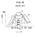
- Fig. 10 also shows the change in the resonance frequencies (fo) and (fv) with temperature when they are relativley set to be (fv>fo) as shown in Fig. 8.
- T H 85°C
- T s 25 °C
- the frequency interval (fov) at ordinary temperature is expanded to (fov H ) (>fov) to cause a remarkable drop in sound pressure.
- the resonance frequency (fo) at ordinary temperature is shifted to (fo L ) (>fo) and the frequency (fv) to (fv L ) ( ⁇ fv).
- the frequency interval (fov) at ordinary temperature is narrowed to (fov L ) ( ⁇ fov) to cause a remarkable rise in sound pressure. Above also result in a remarkable change in sound pressure of 10 dB or more at the reproduced frequency (fw).
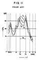
- Fig. 11 shows the sound pressure characteristics of the prior art electroacoustic transducer, where T s represents the characteristic at 25°C, T H at 85 °C, and T L at -40 °C.
- Fig. 12 shows the coil current characteristics corresponding to Fig. 11, where Ts represents the characteristic at 25°C, T H at 85 °C, and T L at -40 °C.
- a difference in sound pressure at -40 °C and 85°C is about 10 dB at the reproduced frequency range (fw) of 2 kHz to 3 kHz.
- the sound pressure characteristic varies with temperature to the extent that the change is sensible by hearing in various applications and seasons.
- An object of the invention is to provide a method of compensating for a change in sound pressure characteristic with temperature of an electroacoustic transducer by utilizing the tendency of the resonance frequencies (fo) and (fv) to vary with temperature.
- the invention provides a method of compensating for a change in sound pressure characteristic with temperature without a major change in the basic structure of a conventional electroacoustic transducer.
- the method according to the invention is, in an electroacoustic transducer comprising a diaphragm disposed in the casing, a resonance chamber provided on the front side of the diaphragm, a driving source provided on the back side of the diaphragm, and the diaphragm being vibrated by the driving source to produce a sound to be emitted through the resonance chamber, characterized in that the resonance frequency(fv) of the resonance chamber is set lower (fv ⁇ fo) than the resonance frequency (fo) of the diaphragm .
- the resonance frequencies (fo) and (fv) of the diaphragm and resonance chamber are relatively set so that the frequency (fv) is lower than the frequency (fo) at ordinary temperature.
- the frequency (fv) tends to rise, the frequency (fo) tends to fall and a magnetic driving force is weakened to decrease the sound pressure.
- the frequency (fv) tends to fall, the frequency (fo) tends to rise, and a magnetic driving force is improved to increase the sound pressure.
- the interval between the resonance frequencies (fo) and (fv) is narrowed to increase the sound pressure, thus offsetting the decrease in sound pressure due to the weakened magnetic driving force.
- the interval is expanded to decrease the sound pressure, thus offsetting the increase in sound pressure due to the improved magnetic driving force. That is, the change in the interval between the resonance frequencies is inversely related to that of the conventional transducer.
- a change in sound pressure caused by a change in driving force is offset by a change in sound pressure caused by a change in frequency interval, thus compensating for a change in sound pressure with temperature to provide a sound pressure characteristic with only a negligible change with temperature.
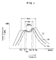
- Fig. 1 is a graph showing an embodiment of the method of compensating for a change in sound pressure characteristic with temperature of an electroacoustic transducer according to the invention.
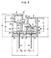
- Fig. 2 is a longitudinal sectional view of an embodiment of the electroacoustic transducer implementing the method shown in Fig. 1.
- Fig. 3 is a longitudinal sectional view showing the dimensional difference between the electroacoustic transducer shown in Fig. 2 and the prior art electroacoustic transducer shown in Fig. 6.
- Fig. 4 is a graph showing the sound pressure characteristics obtained in the electroacoustic transducer shown in Fig. 2.
- Fig. 5 is a graph showing the coil current characteristics obtained in the electroacoustic transducer shown in Fig. 2.
- Fig. 6 is a longitudinal sectional view of a prior art electroacoustic transducer.
- Fig. 7 is a graph showing the sound pressure characteristic obtained in the prior art electroacoustic transducer.
- Fig. 8 is a graph showing the sound pressure characteristic obtained in the prior art electroacoustic transducer.
- Fig. 9 is a graph showing the change in sound pressure characteristics with temperature obtained in the prior art electroacoustic transducer.
- Fig. 10 is a graph showing the change in sound pressure characteristics with temperature obtained in the prior art electroacoustic transducer.
- Fig. 11 is a graph showing the sound pressure characteristics obtained in the prior art electroacoustic-transducer.
- Fig. 12 is a graph showing the coil current characteristics obtained in the prior art electroacoustic transducer.
- Fig. 1 shows an embodiment of the method of compensating for a change in sound pressure characteristic with temperature of an electroacoustic transducer according to the invention.
- This electroacoustic transducer has natural resonance frequencies (fo) and (fv).
- This invention is characterized in that they are relatively set so that the resonance frequency (fv) of the resonance chamber 6 is lower than the resonance frequency (fo) of the diaphragm 4.
- the present invention intends not to suppress changes in the resonance frequencies (fo) and (fv), but, taking into account possible changes in the frequencies with temperature, to differentially set them to the extent that they may approach each other but they are never inversely related.
- the resonance frequency (fo) is determined by the material and shape of the diaphragm 4, the shape and mass of the magnetic piece 16 as an additional mass means, the size of the gap 26, the magnetic force of the magnet 18, the size of the back space 32 of the diaphragm 4, and the diameter of the core 24.
- the resonance frequency (fv) is determined by the equation (1).
- the frequency (fv) of the resonance chamber 6 can be easily adjusted by the volume of the resonance chamber 6 since it is in close relation with its volume.
- the resonance frequency (fo) is decreased to (fo H )( ⁇ fo) at high temperatures and increased to (fo L ) (>fo) at low temperatures.
- Fig. 2 shows an embodiment of the electroacoustic transducer implementing the method according to the invention. It is structually similar to that of the prior art transducer shown in Fig. 6, therefore having the same reference numbers for the parts.
- This transducer has a cylindrical casing 2 made of synthetic resin. On the inner wall surface of the casing 2 are axially provided a plurality of ribs 3. On the back of the ribs 3 a diaphragm 4 is disposed orthogonally to the axis of the casing 2. A resonance chamber 6 is defined on the front side of the diaphragm 4. On the back side thereof a driving source 8 is provided for producing vibrations of the diaphragm 4. A sound emitting hole 10 is provided on the closing surface of the casing 2 extending parallel to the diaphragm 4. The hole 10 has a cylindrical shape projecting into the resonance chamber 6. This allows the resonance chamber 6 to communicate with atmosphere to emit a sound produced by the diaphragm 4 in the resonance chamber 6 to the outside of the casing 2.
- the driving source 8 is a means for producing acoustic vibrations of the diaphragm 4. It is externally supplied with a driving current via terminals 12 and 14 to generate an alternating magnetic field acting on the diaphragm 4 for acoustic vibration.
- the diaphragm 4 is a magnetizable thin metal plate and at the central portion a disk-like magnetic piece 16 is mounted.
- the magnetic piece 16 is an additional mass means for increasing the mass of the diaphragm 4. It is made of a magnetic material to constitute a magnetic circuit in combination with the diaphragm 4. It may be made of a non-magnetizable material only for the purpose of increasing the mass.
- the diaphragm 4 is at the periphery magnetically fixed to the top of a cylindrical magnet 18 contained in the casing 2. That is, the diaphragm 4 is magnetized and secured in position by the magnetic attraction of the magnet 18.
- the magnet 18 is firmly fixed within the casing 2 by a magnetizable metal base 20 closing the back space of the casing 2.
- a substrate 22 To the back surface of the base 20 is secured a substrate 22 with the terminals 12 and 14 mounted thereon.
- the central portions of the base 20 and substrate 22 are penetrated by a cylindrical core 24 extending along the center axis of the magnet 18.
- a gap 26 is defined between an end of the core 24 and the diaphragm 4 for permitting magnetic coupling and vibrations of the diaphragm 4.
- a coil 30 is wound around the core 24 via a bobbin 28 and connected to the terminals 12 and 14.
- An alternating drive current is supplied to the terminals 12 and 14 as an input current to generate an alternating magnetic field at the coil 30 for interlinkage with the diaphragm 4.
- the driving source 8 is surrounded by the cylindrical magnet 18.
- the diaphragm 4, the magnetic piece 16 as an additional mass means, the driving source 8, the cylindrical magnet 18, and the base 20 in combination constitute a closed magnetic circuit.
- the additional mass means is excluded from the closed magnetic circuit if a non-magnetizable material is used instead of the magnetic piece 16.
- Fig. 3 compares this electroacoustic transducer with the prior art transducer.
- the references b2 , c2 , d2 , and e2 show the corresponding dimensions of the prior art transducer. The dimensional relationship are as follows: b1 ⁇ b2 , c1>c2 , d1 ⁇ d2 , and e1>e2.
- the volume ratio of the resonance chamber 6 to the casing 2 can be increased to considerably decrease the resonance frequency (fv). This allows easy setting of the resonance frequency interrelation of (fv ⁇ fo).
- setting the resonance frequency of the resonance chamber lower than the resonance frequency of the diaphragm may compensate for a change in sound pressure characteristic with temperature to provide stable sound pressure characteristic regardless of temperatures. This is also true when a plastic magnet is used, which likely presents a remarkable change in sound pressure characteristic with temperature.
Landscapes
- Physics & Mathematics (AREA)
- Engineering & Computer Science (AREA)
- Acoustics & Sound (AREA)
- Multimedia (AREA)
- Electrostatic, Electromagnetic, Magneto- Strictive, And Variable-Resistance Transducers (AREA)
- Obtaining Desirable Characteristics In Audible-Bandwidth Transducers (AREA)
Abstract
Description
- This invention relates to a method of compensating for a change in sound pressure characteristic with temperature of an electroacoustic transducer, used in the form of a buzzer or sound alarm means, for converting electric signals into sound.
- Electroacoustic transducers convert electric signals into sound. They can be used in the form of buzzers or sound alarm means in various electronic equipments to provide acoustic output corresponding to input electric signals. They have sound pressure characteristics determined by their own structure and materials. Sound pressure characteristics vary with temperature, and a change in sound pressure characteristic has effects on acoustic output.
- Fig. 6 shows a prior art electroacoustic transducer using an electromagnetic coil in a driving source. This transducer has a
cylindrical casing 2 made of synthetic resin. On the inner wall surface of thecasing 2 are axially provided a plurality ofribs 3. On the back side of the ribs 3 adiaphragm 4 is disposed orthogonally to the axis of thecasing 2. Aresonance chamber 6 is defined on the front side of thediaphragm 4. On the back side thereof adriving source 8 is provided for producing vibrations of thediaphragm 4. Asound emitting hole 10 is provided on the closing surface of thecasing 2 extending parallel to thediaphragm 4. Thehole 10 has a cylindrical shape projecting into theresonance chamber 6. This allows theresonance chamber 6 to communicate with atmosphere to emit a sound produced by thediaphragm 4 in theresonance chamber 6 to the outside of thecasing 2. - The
driving source 8 is a means for-producing acoustic vibrations of thediaphragm 4. It is externally supplied with a driving current viaterminals diaphragm 4 for acoustic vibration. Thediaphragm 4 is a magnetizable thin metal plate and at the central portion a disk-likemagnetic piece 16 is mounted. Themagnetic piece 16 is an additional mass means for increasing the mass of thediaphragm 4. It is made of a magnetic material to constitute a magnetic circuit in combination with thediaphragm 4. Thediaphragm 4 is at the periphery magnetically fixed to the top of acylindrical magnet 18 contained in thecasing 2. That is, thediaphragm 4 is magnetized and secured in position by the magnetic attraction of themagnet 18. Themagnet 18 is firmly fixed within thecasing 2 by amagnetizable metal base 20 closing the back space of thecasing 2. To the back surface of thebase 20 is secured asubstrate 22 with theterminals base 20 andsubstrate 22 are penetrated by acylindrical core 24 extending along the center axis of themagnet 18. Agap 26 is defined between an end of thecore 24 and thediaphragm 4 for permitting magnetic coupling and vibrations of thediaphragm 4. Acoil 30 is wound around thecore 24 via abobbin 28 and connected to theterminals terminals coil 30 as an input current for producing vibrations. - It is known that a sound pressure characteristic of above described electroacoustic transducer is structually determined by the
diaphragm 4 andresonance chamber 6. Thediaphragm 4 andresonance chamber 6 have natural resonance frequencies (fo) and (fv) respectively. The resonance frequency (fo) is determined by physical parameters such as the material and shape of thediaphragm 4, the shape and mass of themagnetic piece 16, the size of thegap 26, the magnetic force of themagnet 18, the size of theback space 32 of thediaphragm 4, and the diameter of thecore 24. The resonance frequency (fv) is determined using the following equation:
- The equation (1) is the Helmholtz equation, where V stands for the volume of the
resonance chamber 6, D and L for the diameter and length of thesound emitting hole 10, and C for the sound velocity (approx. 344,000 mm/sec.). That is, the frequency (fv) is determined by the diameter and length of thesound emitting hole 10 and the volume of theresonance chamber 6. If the diameter and length of thesound emitting hole 10 are constant, the frequency (fv) only depends on the volume of theresonance chamber 6. - Fig. 7 shows a measure to increase the sound pressure of the resonance frequency (fo) in the prior art transducer, where the frequency (fv) is set to double (fv=2fo) the frequency (fo). Fig. 8 shows a measure to broaden the frequency range of the sound pressure characteristic, where the frequency (fv) is set slightly higher (fv>fo) than the frequency (fo). A reproduced frequency (fw) is set at the frequency (fo) in the former case and to be in the range of (fo) to (fv) in the latter case.
- It is also known that a sound pressure characteristic varies with temperature in the prior art electroacoustic transducer. Possible factors which influence the characteristic are as follows:
- (a) The
coil 30, a primary part of thedriving source 8, is a wound copper wire. At high temperatures, an increase in the internal resistance of thecoil 30 causes a decrease in current to weaken the generated magnetic field, thus decreasing the driving force to vibrate thediaphragm 4. At low temperatures, the reverse change occurs. - (b) The
magnet 18 is in a magnetic relation with thecore 24 with thecoil 30 wound thereon. At high temperatures, a change in the outer dimensions of themagnet 18 leads to an increase in thegap 26 constituting a part of the magnetic circuit, thus deteriorating the magnetic efficiency. This is noticeable particulary when a plastic magnet is used for themagnet 18. Conversely at low temperatures, the magnetic efficiency is improved. - (c) The magnetic force of the
magnet 18 tends to decrease at high temperatures while increase at low temperatures. - Above factors in combination decrease the resonance frequency (fo) at high temperatures while increase the same at low temperatures.
- A change in the shape and dimensions of the
casing 2 with temperature influences the resonance frequency (fv). Thus, the frequency (fv) also varies with temperature, that is, it is increased at high temperatures and decreased at low temperatures. - Fig. 9 shows the change in the resonance frequencies (fo) and (fv) with temperature when they are relativley set to be (fv=2fo) as shown in Fig. 7. At high temperatures (TH=85°C), the resonance frequency (fo) at ordinary temperature (Ts=25 °C) is shifted to (foH)(<fo) and the frequency (fv) to (fvH (>fv). The frequency interval (fov) at ordinary temperature is expanded to (fovH) (>fov) to cause a remarkable drop in sound pressure. At low temperatures (TL= - 40°C), the resonance frequency (fo) at ordinary temperature is shifted to (foL)(>fo) and the frequency (fv) to (fvL)(<fv). The frequency interval (fov) at ordinary temperature is narrowed to (fovL)(<fov) to cause a remarkable rise in sound pressure. Above result in a remarkable change in sound pressure of 10 dB or more at the reproduced frequency (fw). Required and sufficient acoustic output is not available.
- Fig. 10 also shows the change in the resonance frequencies (fo) and (fv) with temperature when they are relativley set to be (fv>fo) as shown in Fig. 8. At high temperatures (TH=85°C), the resonance frequency (fo) at ordinary temperature (Ts=25 °C) is shifted to (foH) (<fo) and the frequency (fv) to (fvH) (>fv). The frequency interval (fov) at ordinary temperature is expanded to (fovH) (>fov) to cause a remarkable drop in sound pressure. At low temperatures (TL= -40°C ), the resonance frequency (fo) at ordinary temperature is shifted to (foL) (>fo) and the frequency (fv) to (fvL) (<fv). The frequency interval (fov) at ordinary temperature is narrowed to (fovL) (<fov) to cause a remarkable rise in sound pressure. Above also result in a remarkable change in sound pressure of 10 dB or more at the reproduced frequency (fw).
- Fig. 11 shows the sound pressure characteristics of the prior art electroacoustic transducer, where Ts represents the characteristic at 25°C, TH at 85 °C, and TL at -40 °C. Fig. 12 shows the coil current characteristics corresponding to Fig. 11, where Ts represents the characteristic at 25°C, TH at 85 °C, and TL at -40 °C. A difference in sound pressure at -40 °C and 85°C is about 10 dB at the reproduced frequency range (fw) of 2 kHz to 3 kHz.
- As described above, in the prior art electroacoustic transducer, the sound pressure characteristic varies with temperature to the extent that the change is sensible by hearing in various applications and seasons.
- An object of the invention is to provide a method of compensating for a change in sound pressure characteristic with temperature of an electroacoustic transducer by utilizing the tendency of the resonance frequencies (fo) and (fv) to vary with temperature.
- Preferably, the invention provides a method of compensating for a change in sound pressure characteristic with temperature without a major change in the basic structure of a conventional electroacoustic transducer.
- The method according to the invention is, in an electroacoustic transducer comprising a diaphragm disposed in the casing, a resonance chamber provided on the front side of the diaphragm, a driving source provided on the back side of the diaphragm, and the diaphragm being vibrated by the driving source to produce a sound to be emitted through the resonance chamber, characterized in that the resonance frequency(fv) of the resonance chamber is set lower (fv<fo) than the resonance frequency (fo) of the diaphragm .
- In this invention, the resonance frequencies (fo) and (fv) of the diaphragm and resonance chamber are relatively set so that the frequency (fv) is lower than the frequency (fo) at ordinary temperature. At high temperatures, the frequency (fv) tends to rise, the frequency (fo) tends to fall and a magnetic driving force is weakened to decrease the sound pressure. At low temperatures, the frequency (fv) tends to fall, the frequency (fo) tends to rise, and a magnetic driving force is improved to increase the sound pressure. According to the invention, at high temperatures the interval between the resonance frequencies (fo) and (fv) is narrowed to increase the sound pressure, thus offsetting the decrease in sound pressure due to the weakened magnetic driving force. At low temperatures, the interval is expanded to decrease the sound pressure, thus offsetting the increase in sound pressure due to the improved magnetic driving force. That is, the change in the interval between the resonance frequencies is inversely related to that of the conventional transducer. A change in sound pressure caused by a change in driving force is offset by a change in sound pressure caused by a change in frequency interval, thus compensating for a change in sound pressure with temperature to provide a sound pressure characteristic with only a negligible change with temperature.
- Fig. 1 is a graph showing an embodiment of the method of compensating for a change in sound pressure characteristic with temperature of an electroacoustic transducer according to the invention.
- Fig. 2 is a longitudinal sectional view of an embodiment of the electroacoustic transducer implementing the method shown in Fig. 1.
- Fig. 3 is a longitudinal sectional view showing the dimensional difference between the electroacoustic transducer shown in Fig. 2 and the prior art electroacoustic transducer shown in Fig. 6.
- Fig. 4 is a graph showing the sound pressure characteristics obtained in the electroacoustic transducer shown in Fig. 2.
- Fig. 5 is a graph showing the coil current characteristics obtained in the electroacoustic transducer shown in Fig. 2.
- Fig. 6 is a longitudinal sectional view of a prior art electroacoustic transducer.
- Fig. 7 is a graph showing the sound pressure characteristic obtained in the prior art electroacoustic transducer.
- Fig. 8 is a graph showing the sound pressure characteristic obtained in the prior art electroacoustic transducer.
- Fig. 9 is a graph showing the change in sound pressure characteristics with temperature obtained in the prior art electroacoustic transducer.
- Fig. 10 is a graph showing the change in sound pressure characteristics with temperature obtained in the prior art electroacoustic transducer.
- Fig. 11 is a graph showing the sound pressure characteristics obtained in the prior art electroacoustic-transducer.
- Fig. 12 is a graph showing the coil current characteristics obtained in the prior art electroacoustic transducer.
- Now an embodiment of the invention shown in the drawings is described below.
- Fig. 1 shows an embodiment of the method of compensating for a change in sound pressure characteristic with temperature of an electroacoustic transducer according to the invention. This electroacoustic transducer has natural resonance frequencies (fo) and (fv). This invention is characterized in that they are relatively set so that the resonance frequency (fv) of the
resonance chamber 6 is lower than the resonance frequency (fo) of thediaphragm 4. - These frequencies are relatively set at ordinary temperature to such values that they are not inversely related with temperature. The present invention intends not to suppress changes in the resonance frequencies (fo) and (fv), but, taking into account possible changes in the frequencies with temperature, to differentially set them to the extent that they may approach each other but they are never inversely related. To determine the frequencies (fo) and (fv), the above mentioned physical parameters and equation can be utilized. That is, the resonance frequency (fo) is determined by the material and shape of the
diaphragm 4, the shape and mass of themagnetic piece 16 as an additional mass means, the size of thegap 26, the magnetic force of themagnet 18, the size of theback space 32 of thediaphragm 4, and the diameter of thecore 24. The resonance frequency (fv) is determined by the equation (1). Especially, the frequency (fv) of theresonance chamber 6 can be easily adjusted by the volume of theresonance chamber 6 since it is in close relation with its volume. - The resonance frequency (fv) is increased to (fvH) (>fv) at high temperatures (=TH) and decreased to (fvL) (<fv) at low temperatures (=TL). The resonance frequency (fo) is decreased to (foH )(<fo) at high temperatures and increased to (foL) (>fo) at low temperatures. These possible changes are unique characteristics of this kind of electroacoustic transducers as described referring to Figs. 9 and 10. This is true to the invention with the frequency (fv) set lower than the frequency (fo).
- With the frequency (fv) set lower than the frequency (fo), the frequencies (fo) and (fv) are shifted to (foH) and (fvH) to approach each other at high temperatures (=TH) so that the frequency interval becomes narrower (fovH) than that (fov) at ordinary temperature .
- Referring to the structure of the prior art shown in Fig. 6, above mentioned (a)-(c) factors weaken the magnetic driving force to decrease the sound pressure, but in the electroacoustic transducer according to the invention, the frequency interval is narrowed (fov>fovH) to increase the sound pressure. In other words, a decrease in sound pressure due to the weakened driving force is offset by an increase in sound pressure due to the narrowed frequency interval, thus suppressing a remarkable drop in sound pressure.
- At low temperatures (=TL), the frequencies (fo) and (fv) are shifted to (foL) and (fvL) to move away from each other so that the frequency interval becomes wider (fovL) than that (fov) at ordinary temperature.
- Referring to the structure of the prior art shown in Fig. 6, above mentioned (a)-(c) factors improve the magnetic driving force to increase the sound pressure, but in the electroacoustic transducer according to the invention, the frequency interval is expanded (fov<fovL) to decrease the sound pressure. In other words, an increase in sound pressure due to the improved driving force is offset by a decrease in sound pressure due to the expanded frequency interval, thus suppressing a remarkable rise in sound pressure.
- As described above, setting the resonance frequency (fv) lower than the resonance frequency (fo) compensates for a change in sound pressure with temperature to provide a sound pressure characteristic with only a negligible change with temperature within the reproduced frequency range.
- Fig. 2 shows an embodiment of the electroacoustic transducer implementing the method according to the invention. It is structually similar to that of the prior art transducer shown in Fig. 6, therefore having the same reference numbers for the parts.
- This transducer has a
cylindrical casing 2 made of synthetic resin. On the inner wall surface of thecasing 2 are axially provided a plurality ofribs 3. On the back of the ribs 3 adiaphragm 4 is disposed orthogonally to the axis of thecasing 2. Aresonance chamber 6 is defined on the front side of thediaphragm 4. On the back side thereof a drivingsource 8 is provided for producing vibrations of thediaphragm 4. Asound emitting hole 10 is provided on the closing surface of thecasing 2 extending parallel to thediaphragm 4. Thehole 10 has a cylindrical shape projecting into theresonance chamber 6. This allows theresonance chamber 6 to communicate with atmosphere to emit a sound produced by thediaphragm 4 in theresonance chamber 6 to the outside of thecasing 2. - The driving
source 8 is a means for producing acoustic vibrations of thediaphragm 4. It is externally supplied with a driving current viaterminals diaphragm 4 for acoustic vibration. Thediaphragm 4 is a magnetizable thin metal plate and at the central portion a disk-likemagnetic piece 16 is mounted. Themagnetic piece 16 is an additional mass means for increasing the mass of thediaphragm 4. It is made of a magnetic material to constitute a magnetic circuit in combination with thediaphragm 4. It may be made of a non-magnetizable material only for the purpose of increasing the mass. - The
diaphragm 4 is at the periphery magnetically fixed to the top of acylindrical magnet 18 contained in thecasing 2. That is, thediaphragm 4 is magnetized and secured in position by the magnetic attraction of themagnet 18. Themagnet 18 is firmly fixed within thecasing 2 by amagnetizable metal base 20 closing the back space of thecasing 2. To the back surface of thebase 20 is secured asubstrate 22 with theterminals base 20 andsubstrate 22 are penetrated by acylindrical core 24 extending along the center axis of themagnet 18. Agap 26 is defined between an end of thecore 24 and thediaphragm 4 for permitting magnetic coupling and vibrations of thediaphragm 4. Acoil 30 is wound around thecore 24 via abobbin 28 and connected to theterminals terminals coil 30 for interlinkage with thediaphragm 4. The drivingsource 8 is surrounded by thecylindrical magnet 18. In this electroacoustic transducer, thediaphragm 4, themagnetic piece 16 as an additional mass means, the drivingsource 8, thecylindrical magnet 18, and the base 20 in combination constitute a closed magnetic circuit. The additional mass means is excluded from the closed magnetic circuit if a non-magnetizable material is used instead of themagnetic piece 16. - Fig. 3 compares this electroacoustic transducer with the prior art transducer. According to the invention, the diameter (=a) of the
casing 2 is the same, the height b1 of thecasing 2 is lower, the volume ratio of theresonance chamber 6 to thecasing 2, i.e. the height c₁ is higher, the height d₁ of themagnet 18 is lower, and the diameter e1 of themagnet 18 is larger. The references b₂ , c₂ , d₂ , and e₂ show the corresponding dimensions of the prior art transducer. The dimensional relationship are as follows: b₁<b₂ , c₁>c₂ , d₁ < d₂ , and e₁>e₂. - The volume ratio of the
resonance chamber 6 to thecasing 2 can be increased to considerably decrease the resonance frequency (fv). This allows easy setting of the resonance frequency interrelation of (fv< fo). The electroacoustic transducer, with the frequency (fv) set lower than (fo), will provide sound pressure characteristics, as shown in Fig. 1 where TL= -40°C, Ts=25°C, and TH=85°C, with only a negligible change in sound pressure of about 1 dB. - Figs. 4 and 5 show the sound pressure and corresponding coil current characteristics of the electroacoustic transducer with the frequency (fv) set lower than (fo), where TL=-40°C, TS=25°C, and TH=85°C. The sound pressure characteristics within the reproduced frequency range (fw) (=1.7kHz to 2.2kHz) show only a negligible change of about 1 dB. This proves that the method acccording to the invention will compensate for a change in sound pressure characteristic with temperature.
- As described above, according to the invention, setting the resonance frequency of the resonance chamber lower than the resonance frequency of the diaphragm may compensate for a change in sound pressure characteristic with temperature to provide stable sound pressure characteristic regardless of temperatures. This is also true when a plastic magnet is used, which likely presents a remarkable change in sound pressure characteristic with temperature.
Claims (12)
- A method of compensating for a change in sound pressure characteristic with temperature of an electroacoustic transducer comprising a diaphragm disposed in a casing, a resonance chamber provided on the front side of said diaphragm, a driving source provided on the back side of said diaphragm, and said diaphragm being vibrated by said driving source to produce a sound to be emitted through said resonance chamber, being characterized in that a resonance frequency of said resonance chamber is set lower than a resonance frequency of said diaphragm.
- The method of compensating for a change in sound pressure characteristic with temperature of an electroacoustic transducer comprising a diaphragm disposed in a casing, a resonance chamber provided on the front side of said diaphragm, a driving source provided on the back side of said diaphragm, and said diaphragm being vibrated by said driving source to produce a sound to be emitted through said resonance chamber according to claim 1, comprising:
setting said resonance frequency of the resonance chamber lower than said resonance frequency of the diaphragm at ordinary temperature;
compensating for a decrease in sound pressure at high temperatures above said ordinary temperature by narrowing a frequency interval between said resonance frequency of the resonance chamber and said resonance frequency of the diaphragm to improve a magnetic driving force of said driving source; and
compensating for an increase in sound pressure at low temperatures below said ordinary temperature by expanding a frequency interval between said resonance frequency of the resonance chamber and said resonance frequency of the diaphragm to decrease a magnetic driving force of said driving source. - The method of compensating for a change in sound pressure characteristic with temperature of an electroacoustic transducer comprising a diaphragm disposed in a casing, a resonance chamber provided on the front side of said diaphragm, a driving source provided on the back side of said diaphragm, and said diaphragm being vibrated by said driving source to produce a sound to be emitted through said resonance chamber according to claim 1, comprising:
setting said resonance frequency of the resonance chamber lower than said resonance frequency of the diaphragm at ordinary temperature;
compensating for a decrease in sound pressure at high temperatures above said.ordinary temperature by increasing said resonance frequency of the resonance chamber and decreasing said resonance frequency of the diaphragm to narrow a frequency interval therebetween so as to improve a magnetic driving force of said driving source; and
compensating for an increase in sound pressure at low temperatures below said ordinary temperature by decreasing said resonance frequency of the resonance chamber and increasing said resonance frequency of the diaphragm to expand a frequency interval therebetween so as to weaken a magnetic driving force of said driving source. - The method of compensating for a change in sound pressure characteristic with temperature of an electroacoustic transducer according to claims 1, 2 and 3, wherein said resonance frequency of the resonance chamber is set lower than said resonance frequency of the diaphragm at ordinary temperature to the extent that they are not inversely related with temperature.
- The method of compensating for a change in sound pressure characteristic with temperature of an electroacoustic transducer according to claim 1, wherein said resonance frequency of the resonance chamber is set lower than said resonance frequency of the diaphragm by increasing a volume ratio of said resonance chamber to said casing.
- The method of compensating for a change in sound pressure characteristic with temperature of an electroacoustic transducer according to claim 1, wherein said resonance chamber is provided within said casing of a cylindrical shape and closed by said diaphragm disposed at the middle portion of the casing, and communicates with atmosphere through a sound emitting hole provided on the casing.
- The method of compensating for a change in sound pressure characteristic with temperature of an electroacoustic transducer according to claim 1, wherein a sound emitting hole, having a cylindrical shape formed on the inner wall surface of said casing, projects into said resonance chamber.
- The method of compensating for a change in sound pressure characteristic with temperature of an electroacoustic transducer according to claim 1, wherein the diaphragm is disk-like corresponding to the shape of the casing and an additional mass means mounted thereon.
- The method of compensating for a change in sound pressure characteristic with temperature of an electroacoustic transducer according to claim 1, wherein the diaphragm is a plate made of magnetizable material disposed between a plurality of ribs protruded on the inner wall surface of said resonance chamber and a cylindrical magnet fixed within said casing, and the periphery of the diaphragm is fixed by magnetic attraction of said cylindrical magnet.
- The method of compensating for a change in sound pressure characteristic with temperature of an electroacoustic transducer according to claim 1, wherein said diaphragm, an additional mass means fixed to the diaphragm, said driving source, a cylindrical magnet surrounding said driving source, and a base supporting said magnet in combination constitute a closed magnetic circuit within said casing.
- The method of compensating for a change in sound pressure characteristic with temperature of an electroacoustic transducer according to claim 1, wherein said driving source comprises a coil wound around a core fixed to a base, and the coil is externally supplied with an alternating driving current to generate an alternating magnetic field acting on said diaphragm.
- The method of compensating for a change in sound pressure characteristic with temperature of an electroacoustic transducer according to claim 1, wherein a base and substrate are mounted to close the back opening of said casing and from the substrate terminals are drawn out for supplying electricity to a coil.
Applications Claiming Priority (2)
| Application Number | Priority Date | Filing Date | Title |
|---|---|---|---|
| JP186138/92 | 1992-06-20 | ||
| JP18613892A JPH066899A (en) | 1992-06-20 | 1992-06-20 | Temperature compensation method for sound pressure characteristic of electroacoustic transducer |
Publications (3)
| Publication Number | Publication Date |
|---|---|
| EP0576216A2 true EP0576216A2 (en) | 1993-12-29 |
| EP0576216A3 EP0576216A3 (en) | 1994-08-31 |
| EP0576216B1 EP0576216B1 (en) | 1999-03-17 |
Family
ID=16183046
Family Applications (1)
| Application Number | Title | Priority Date | Filing Date |
|---|---|---|---|
| EP19930304780 Expired - Lifetime EP0576216B1 (en) | 1992-06-20 | 1993-06-18 | Method of compensating for a change in sound pressure characteristic with temperature of an elecrtoacoustic transducer |
Country Status (4)
| Country | Link |
|---|---|
| EP (1) | EP0576216B1 (en) |
| JP (1) | JPH066899A (en) |
| CN (1) | CN1038095C (en) |
| DE (1) | DE69323930T2 (en) |
Cited By (3)
| Publication number | Priority date | Publication date | Assignee | Title |
|---|---|---|---|---|
| EP1120995A3 (en) * | 2000-01-24 | 2003-08-13 | Star Micronics Co., Ltd. | Electroacoustic transducer and method of manufacturing the same |
| EP3382691A1 (en) * | 2017-03-30 | 2018-10-03 | Mitsuba Corporation | Horn device |
| US12549907B2 (en) | 2021-11-26 | 2026-02-10 | Murata Manufacturing Co., Ltd. | Ultrasonic transducer |
Families Citing this family (3)
| Publication number | Priority date | Publication date | Assignee | Title |
|---|---|---|---|---|
| JP4802998B2 (en) * | 2005-12-19 | 2011-10-26 | セイコーエプソン株式会社 | Electrostatic ultrasonic transducer drive control method, electrostatic ultrasonic transducer, ultrasonic speaker using the same, audio signal reproduction method, superdirective acoustic system, and display device |
| KR102857416B1 (en) * | 2020-11-27 | 2025-09-09 | 현대자동차주식회사 | vehicle, and controlling method thereof |
| CN112827787B (en) * | 2021-01-07 | 2022-06-21 | 歌尔微电子股份有限公司 | Ultrasonic transducer |
Family Cites Families (2)
| Publication number | Priority date | Publication date | Assignee | Title |
|---|---|---|---|---|
| SE435777B (en) * | 1979-01-29 | 1984-10-15 | Ibuki Kogyo Co Ltd | ELECTRIC HORN |
| JPS59150880A (en) * | 1983-02-14 | 1984-08-29 | 国産金属工業株式会社 | Door lock |
-
1992
- 1992-06-20 JP JP18613892A patent/JPH066899A/en active Pending
-
1993
- 1993-06-18 EP EP19930304780 patent/EP0576216B1/en not_active Expired - Lifetime
- 1993-06-18 DE DE1993623930 patent/DE69323930T2/en not_active Expired - Fee Related
- 1993-06-19 CN CN 93107429 patent/CN1038095C/en not_active Expired - Fee Related
Cited By (5)
| Publication number | Priority date | Publication date | Assignee | Title |
|---|---|---|---|---|
| EP1120995A3 (en) * | 2000-01-24 | 2003-08-13 | Star Micronics Co., Ltd. | Electroacoustic transducer and method of manufacturing the same |
| EP3382691A1 (en) * | 2017-03-30 | 2018-10-03 | Mitsuba Corporation | Horn device |
| CN108696802A (en) * | 2017-03-30 | 2018-10-23 | 株式会社美姿把 | loudspeaker device |
| CN108696802B (en) * | 2017-03-30 | 2021-02-19 | 株式会社美姿把 | Horn device |
| US12549907B2 (en) | 2021-11-26 | 2026-02-10 | Murata Manufacturing Co., Ltd. | Ultrasonic transducer |
Also Published As
| Publication number | Publication date |
|---|---|
| EP0576216A3 (en) | 1994-08-31 |
| CN1038095C (en) | 1998-04-15 |
| JPH066899A (en) | 1994-01-14 |
| EP0576216B1 (en) | 1999-03-17 |
| DE69323930T2 (en) | 1999-08-26 |
| CN1083300A (en) | 1994-03-02 |
| DE69323930D1 (en) | 1999-04-22 |
Similar Documents
| Publication | Publication Date | Title |
|---|---|---|
| TWI798358B (en) | Panel audio loudspeaker electromagnetic actuator | |
| US6907955B2 (en) | Electromagnetic electroacoustic transducer | |
| US4901357A (en) | Electromagnetic transducer | |
| JP7203213B2 (en) | Moving magnet actuator with coil for panel audio speaker | |
| EP0576216A2 (en) | Method of compensating for a change in sound pressure characteristic with temperature of an electoacoustic transducer | |
| CN1620193B (en) | speaker equipment | |
| US4147899A (en) | Broadband electromagnetic sound source with differently tuned diaphragms | |
| US4330878A (en) | Sound producing device for watches | |
| US4159472A (en) | Electronic buzzer | |
| EP0475208A2 (en) | Electroacoustic piezoelectric transducer | |
| KR930008730B1 (en) | Dynamic speaker | |
| CN114424584A (en) | Moving Magnet Actuator with Voice Coil | |
| US6023519A (en) | Electroacoustic transducer | |
| JPS5936479B2 (en) | Electromagnetic acoustic transducer | |
| JPH0630497A (en) | Electro-acoustic transducer | |
| US2715192A (en) | Transducer | |
| JP2549375Y2 (en) | Electromagnetic converter | |
| JPS6025118Y2 (en) | sound device | |
| JP2571811Y2 (en) | Alarm device | |
| JPS6344879Y2 (en) | ||
| CN107172544B (en) | Vibrator and electronic device | |
| JPS6237271Y2 (en) | ||
| JPH08186894A (en) | Electromagnetic acoustic transducer | |
| JPH07327296A (en) | Electromagnetic sound transducer | |
| JPS6313559B2 (en) |
Legal Events
| Date | Code | Title | Description |
|---|---|---|---|
| PUAI | Public reference made under article 153(3) epc to a published international application that has entered the european phase |
Free format text: ORIGINAL CODE: 0009012 |
|
| AK | Designated contracting states |
Kind code of ref document: A2 Designated state(s): DE FR GB |
|
| PUAL | Search report despatched |
Free format text: ORIGINAL CODE: 0009013 |
|
| AK | Designated contracting states |
Kind code of ref document: A3 Designated state(s): DE FR GB |
|
| 17P | Request for examination filed |
Effective date: 19941230 |
|
| GRAG | Despatch of communication of intention to grant |
Free format text: ORIGINAL CODE: EPIDOS AGRA |
|
| 17Q | First examination report despatched |
Effective date: 19970922 |
|
| GRAG | Despatch of communication of intention to grant |
Free format text: ORIGINAL CODE: EPIDOS AGRA |
|
| GRAG | Despatch of communication of intention to grant |
Free format text: ORIGINAL CODE: EPIDOS AGRA |
|
| GRAH | Despatch of communication of intention to grant a patent |
Free format text: ORIGINAL CODE: EPIDOS IGRA |
|
| GRAH | Despatch of communication of intention to grant a patent |
Free format text: ORIGINAL CODE: EPIDOS IGRA |
|
| GRAA | (expected) grant |
Free format text: ORIGINAL CODE: 0009210 |
|
| AK | Designated contracting states |
Kind code of ref document: B1 Designated state(s): DE FR GB |
|
| REF | Corresponds to: |
Ref document number: 69323930 Country of ref document: DE Date of ref document: 19990422 |
|
| ET | Fr: translation filed | ||
| PLBE | No opposition filed within time limit |
Free format text: ORIGINAL CODE: 0009261 |
|
| STAA | Information on the status of an ep patent application or granted ep patent |
Free format text: STATUS: NO OPPOSITION FILED WITHIN TIME LIMIT |
|
| 26N | No opposition filed | ||
| REG | Reference to a national code |
Ref country code: GB Ref legal event code: IF02 |
|
| PGFP | Annual fee paid to national office [announced via postgrant information from national office to epo] |
Ref country code: FR Payment date: 20030610 Year of fee payment: 11 |
|
| PGFP | Annual fee paid to national office [announced via postgrant information from national office to epo] |
Ref country code: GB Payment date: 20030618 Year of fee payment: 11 |
|
| PG25 | Lapsed in a contracting state [announced via postgrant information from national office to epo] |
Ref country code: GB Free format text: LAPSE BECAUSE OF NON-PAYMENT OF DUE FEES Effective date: 20040618 |
|
| GBPC | Gb: european patent ceased through non-payment of renewal fee |
Effective date: 20040618 |
|
| PG25 | Lapsed in a contracting state [announced via postgrant information from national office to epo] |
Ref country code: FR Free format text: LAPSE BECAUSE OF NON-PAYMENT OF DUE FEES Effective date: 20050228 |
|
| REG | Reference to a national code |
Ref country code: FR Ref legal event code: ST |
|
| PGFP | Annual fee paid to national office [announced via postgrant information from national office to epo] |
Ref country code: DE Payment date: 20050616 Year of fee payment: 13 |
|
| PG25 | Lapsed in a contracting state [announced via postgrant information from national office to epo] |
Ref country code: DE Free format text: LAPSE BECAUSE OF NON-PAYMENT OF DUE FEES Effective date: 20070103 |