EP0576016A1 - Diagnostic system using nuclear magnetic resonance phenomenon - Google Patents
Diagnostic system using nuclear magnetic resonance phenomenon Download PDFInfo
- Publication number
- EP0576016A1 EP0576016A1 EP93110132A EP93110132A EP0576016A1 EP 0576016 A1 EP0576016 A1 EP 0576016A1 EP 93110132 A EP93110132 A EP 93110132A EP 93110132 A EP93110132 A EP 93110132A EP 0576016 A1 EP0576016 A1 EP 0576016A1
- Authority
- EP
- European Patent Office
- Prior art keywords
- magnetic resonance
- high frequency
- nuclear magnetic
- resonance signal
- measuring device
- Prior art date
- Legal status (The legal status is an assumption and is not a legal conclusion. Google has not performed a legal analysis and makes no representation as to the accuracy of the status listed.)
- Granted
Links
Images


Classifications
-
- G—PHYSICS
- G01—MEASURING; TESTING
- G01R—MEASURING ELECTRIC VARIABLES; MEASURING MAGNETIC VARIABLES
- G01R33/00—Arrangements or instruments for measuring magnetic variables
- G01R33/20—Arrangements or instruments for measuring magnetic variables involving magnetic resonance
- G01R33/28—Details of apparatus provided for in groups G01R33/44 - G01R33/64
- G01R33/32—Excitation or detection systems, e.g. using radio frequency signals
- G01R33/34—Constructional details, e.g. resonators, specially adapted to MR
- G01R33/34084—Constructional details, e.g. resonators, specially adapted to MR implantable coils or coils being geometrically adaptable to the sample, e.g. flexible coils or coils comprising mutually movable parts
-
- A—HUMAN NECESSITIES
- A61—MEDICAL OR VETERINARY SCIENCE; HYGIENE
- A61B—DIAGNOSIS; SURGERY; IDENTIFICATION
- A61B5/00—Measuring for diagnostic purposes; Identification of persons
- A61B5/05—Detecting, measuring or recording for diagnosis by means of electric currents or magnetic fields; Measuring using microwaves or radio waves
- A61B5/055—Detecting, measuring or recording for diagnosis by means of electric currents or magnetic fields; Measuring using microwaves or radio waves involving electronic [EMR] or nuclear [NMR] magnetic resonance, e.g. magnetic resonance imaging
-
- G—PHYSICS
- G01—MEASURING; TESTING
- G01R—MEASURING ELECTRIC VARIABLES; MEASURING MAGNETIC VARIABLES
- G01R33/00—Arrangements or instruments for measuring magnetic variables
- G01R33/20—Arrangements or instruments for measuring magnetic variables involving magnetic resonance
- G01R33/28—Details of apparatus provided for in groups G01R33/44 - G01R33/64
- G01R33/285—Invasive instruments, e.g. catheters or biopsy needles, specially adapted for tracking, guiding or visualization by NMR
-
- G—PHYSICS
- G01—MEASURING; TESTING
- G01R—MEASURING ELECTRIC VARIABLES; MEASURING MAGNETIC VARIABLES
- G01R33/00—Arrangements or instruments for measuring magnetic variables
- G01R33/20—Arrangements or instruments for measuring magnetic variables involving magnetic resonance
- G01R33/28—Details of apparatus provided for in groups G01R33/44 - G01R33/64
- G01R33/288—Provisions within MR facilities for enhancing safety during MR, e.g. reduction of the specific absorption rate [SAR], detection of ferromagnetic objects in the scanner room
-
- G—PHYSICS
- G01—MEASURING; TESTING
- G01R—MEASURING ELECTRIC VARIABLES; MEASURING MAGNETIC VARIABLES
- G01R33/00—Arrangements or instruments for measuring magnetic variables
- G01R33/20—Arrangements or instruments for measuring magnetic variables involving magnetic resonance
- G01R33/28—Details of apparatus provided for in groups G01R33/44 - G01R33/64
- G01R33/32—Excitation or detection systems, e.g. using radio frequency signals
- G01R33/36—Electrical details, e.g. matching or coupling of the coil to the receiver
- G01R33/3642—Mutual coupling or decoupling of multiple coils, e.g. decoupling of a receive coil from a transmission coil, or intentional coupling of RF coils, e.g. for RF magnetic field amplification
- G01R33/3657—Decoupling of multiple RF coils wherein the multiple RF coils do not have the same function in MR, e.g. decoupling of a transmission coil from a receive coil
Abstract
Description
- The present invention relates to a diagnostic system using a nuclear magnetic resonance phenomenon wherein a nuclear magnetic resonance signal receiving coil is inserted to a human body and a nuclear magnetic resonance image is formed.
- Conventionally, in the detection and diagnosis of a surface of a digestive organ of a human body, particularly to epidermal cancer generated in stomach walls or an upper layer of the intestinal canal, the general method was that the generated portion was detected by an endoscope or an X-ray diagnosis, and tissues of a living body of the generated portion was picked up, and was determined whether it is malignant or not.
- However, in such a conventional method, since the sampling portion became a relatively wide range, there were problems in that the result of the diagnosis was not able to be determined, and it took much time to pick up the tissues of the living body, and the human body was damaged.
- On the other hand, there has recently been widely used a non-attacking diagnosing method for a human body which utilizes a nuclear-magnetic resonance phenomenon (the nuclear-magnetic resonance being hereinafter referred to as the "MR"). With a magnetic resonance imaging device (the magnetic resonance imaging being hereinafter referred to as the "MRI"), a human body is placed in a static magnetic field, and a predetermined high frequency magnetic field is applied to the human body to excite nuclei having spins of the tissues in the body cavity of the human body. MR signals having a predetermined frequency produced until the excited nuclei return to the original positions are detected and processed by a computer to obtain vertical cross-sectional images of the body cavity of the human body.
- The cross-sectional image obtained by the MRI device are extremely effective for diagnosis such as distinction of abnormal cells such as cells suffered from cancer from normal cells. It is known that MR signals from cancer tissues and normal tissues are generated at different relaxation time. Therefore, it is possible to diagnose whether the living tissues to be examined are suffered from cancer or not by imaging a difference between the MR signals in density based on the relaxation time.
- Fine and accurate images must be obtained to diagnose diseases of the digestive system such as as a tubular viscus and particularly to find the depths of its affected portions. However, since the MR signal receiving body coil is provided externally of a patient body with the conventional apparatus, it is difficult to obtain fine and accurate cross sectional images of depth portions of the tubular viscus of the patient. For example, with a conventional system, a surface coil or receiving MR signals is placed on the abdomen of a patient and receives MR signals is placed on the abdomen of a patient and receives MR signals to diagnose the stomach walls. However, the signal-to-noise ratio (hereinafter referred to as the "SN ratio") is too low to obtain images sufficient for required diagnosis.
- In order to overcome this problem, there has been proposed an insertion apparatus such as an endoscope or a probe, which is provided, on the distal end of an insertion section inserted in the body of a patient, with an MR signal receiving high frequency coil, for detecting MR signals, as disclosed in Published Examined Japanese Patent Application No. 3-5174 and Published Unexamined Patent Application No. 2-277440. With them, a coil inserted in the patient's body receives MR signals and provides fine and accurate images having a good SN ratio. Thus, fine and accurate images can be obtained for diagnosing the depths of affected portions of tubular viscus.
- However, the conventional nuclear magnetic resonance diagnostic apparatus is structured as shown in Fig. 1. More specifically,
reference numeral 1 is an MRI apparatus, which comprises an MRsignal measuring device 2. On the other hand, in the inside of a top end portion of aninsertion section 5 of anendoscope 4 inserted to the body cavity of apatient 3, a high frequency coil, which is an MR antenna for receiving an MR signal. - The high frequency coil is connected to a
cable 8 through a matching circuit arranged in thetop end portion 5 of theendoscope 4. The matching circuit matches impedance between the high frequency coil and thecable 8, and thecable 8 transmits the MR signal received by the high frequency coil. Thecable 8 is connected to the MR signal measuringdevice 2 through afront amplifier 9, and auniversal code 10 of the endoscope is connected to a lightpower source device 11. - In such a conventional nuclear magnetic resonance diagnostic apparatus, the high frequency coil provided in the
insertion section 5 of theendoscope 4 is not electrically insulated/separated from the nuclear magnetic resonancesignal measuring device 2. In other words, in the endoscope with the built-in high frequency coil or the probe, the portion including the matching circuit and thecable 8 is in an electrically conductive live state. - In the
conventional endoscope 4 or the probe, if the outer sheath of theinsertion portion 5 is broken and thehigh frequency coil 6 and the nucous membrane of the living body is in a conductive state, there is fear that leakage current a will flow to thepatient 3. - The present invention has been made in consideration of the above-mentioned problems, and an abject of the present invention is to provide a nuclear magnetic resonance diagnostic system wherein safety, in view of the patient leakage current, can be ensured with high reliability even if a high frequency coil is provided in an insertion section inserted to a human cavity.
- According to the present invention, there is provided a diagnostic system a nuclear magnetic resonance phenomenon comprising an external magnetic field generator, provided externally, for generating a magnetic field in a living body, a thin diameter member capable of inserting to a body cavity and having flexibility, a high frequency coil, provided at a top end of the thin diameter member, for transmitting and receiving a high frequency, a nuclear magnetic resonance signal measuring device for receiving a nuclear magnetic resonance signal from the living body, and insulating and separating means, provided between the high frequency coil and the nuclear magnetic resonance signal measuring device, for electrically insulating and separating both high frequency coil and nuclear magnetic resonance signal measuring device in a manner that the nuclear magnetic resonance signal is transmittable between the high frequency coil and the nuclear magnetic resonance signal measuring device.
- An external magnetic field generator receives a nuclear magnetic resonance signal from, e.g., an excited hydrogen atom by the high frequency coil provided in the top end portion of the insertion section inserted to the body cavity of the patient. The nuclear magnetic resonance signal received by the high frequency coil is transmitted to the nuclear magnetic resonance signal measuring means of the external magnetic field generator separated by the separating means, and such received, transmitted and insulated unclear magnetic resonance signal is processed by the external magnetic field generator, and a nuclear magnetic resonance signal image can be formed.
- According to the diagnostic system of the present invention, safety of the patient in view of electrical leakage can be ensured without deteriorating the quality of the MRI image, and extremely fine and accurate MR image-diagnosis can be performed in a safe state of MR diagnosis.
- This invention can be more fully understood from the following detailed description when taken in conjunction with the accompanying drawings, in which:
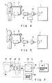
- Fig. 1 is a schematic structural view of a conventional MRI apparatus;
- Fig. 2 is a schematic view of an MRI apparatus for diagnostic system according to the present invention;
- Fig. 3 is a schematic perspective view of a portion where an endoscope using the MRI apparatus of Fig. 1 is inserted;
- Fig. 4 is a view of an MRI apparatus according to the other embodiment of the present invention similar to Fig. 2;
- Fig. 5 is a view of an MRI apparatus according to a modification of the present invention similar to Fig. 2;
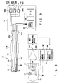
- Fig. 6 is a schematic view showing a state that the endoscope using the diagnosis system of the present invention, an MR signal measuring device, and a camera control unit are connected;
- Fig. 7 is a schematic circuit diagram of the endoscope of Fig. 6;
- Fig. 8 is a schematic view showing a modification of the endoscope of Figs. 6 and 7;
- Fig. 9 is a view of an endoscope of the other modification similar to Fig. 6;
- Fig. 10 is a schematic view showing a static magnetic field in the diagnostic system;
- Fig. 11 is an explanatory view showing a direction where electromagnetic parts are provided in the static magnetic field;
- Fig. 12 is an explanatory view schematically showing a direction where the MRI apparatus is provided;
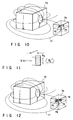
- Fig. 13 is a perspective view showing a state that a light source device for endoscope is provided in the static magnetic field;
- Fig. 14 is an explanatory view showing a state that a light source device is provided in the vicinity of a magnet of the MRI apparatus;
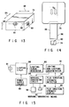
- Fig. 15 is a block diagram schematically showing the structure of the light source device for endoscope;
- Fig. 16 is a schematic perspective view showing a top end portion of the endoscope;
- Fig. 17 is a perspective view showing a state that the MRI apparatus is used;
- Figs. 18A to 18L are schematic perspective views showing various types of treatment implements for endoscope;
- Fig. 19 is a schematic perspective view showing the MRI apparatus having a hanger for endoscope;
- Fig. 20 is a perspective view showing the hanger for endoscope; and
- Fig. 21 is a schematic perspective view showing the MRI apparatus having a trolley for endoscope.
- Embodiments of the present invention will be explained with reference to the drawings. It is noted that the same reference numerals are added the same portions through all figures.
- Figs. 2 and 3 show a first embodiment of a diagnostic system using a unclear magnetic resonance phenomenon. An MR signal receiver of an MRI apparatus or an MR
signal measuring device 2 is connected to a front-stage amplifier 9 through aseparating means 12. Ahigh frequency coil 6, which is a MR antenna for receiving an MR signal, is provided in a top end portion of aninsertion portion 5 of anendoscope 4, which is inserted to a cavity of aliving body 3 of a patient to be examined. Thehigh frequency coil 6 and the front-stage amplifier 9 are connected to each other via acable 8. - The
high frequency coil 6 is connected to thecable 6 through matching means orcircuit 7. The matchingcircuit 7 matches impedance of thehigh frequency coil 6 andcable 8. Thecable 8 transmits the MR signal received by thehigh frequency coil 6. Thecable 8 is connected to the MR signal measuringdevice 2 through thefront amplifier 9, and auniversal code 10 of theendoscope 4 is connected to alight source device 11. - Separating
means 12 is formed of, e.g., transformer. If a side, which is connected to the MR signal measuringdevice 2, is a primary side and a side, which is connected to thehigh frequency coil 6, is a secondary side, a stabilizing d.c.voltage source 13 for supplying a bias voltage to the front-stage amplifier 9, e.g., a battery to which a voltage stabilizing circuit is attached is connected to the secondary side. - According to the above-structured nuclear magnetic resonance diagnostic apparatus, the
MRI apparatus 1 receives an MR signal sent from, e.g., a hydrogen atom by use of thehigh frequency coil 6 provided at the top end portion of theinsertion portion 5 of the endoscope inserted to the cavity of the livingbody 3 of a patient. - The MR signal received by the
high frequency coil 6 is transmitted to thecable 8, whose impedance is matched by thematching circuit 7, and the received MR signal is amplified by the front-stage amplifier 9 using the stabilizing d.c.voltage source 13 as a power source. - The MR
signal measuring device 2 of theMRI apparatus 1 is electrically isolated/separated from thehigh frequency coil 6, which is connected to thecable 8, by separatingmeans 12 such as transformer, and the MR signal is transmitted to the MRsignal measuring device 2 of theMRI apparatus 1. The MR signal, which is received by the MRsignal measuring device 2, and transmitted, and isolated, is processed by theMRI apparatus 1, and an MR signal image is formed. - According to the above embodiment, a patient circuit forms the
high frequency coil 6, thematching circuit 7, and thecable 8 for transmitting the signal, which are isolated/separated from theMRI apparatus 1. - Due to this, it is possible to control a patient leakage current, which flows to an earth from the
MRI apparatus 1 via thehigh frequency coil 6 and thepatient 3. Therefore, the leakage current to a patient mounting portion can be controlled to be lower than an allowable value, which is defined by IEC 601-1. Moreover, in the case that thehigh frequency coil 6 is inserted to the living body of the patient and the MR image diagnosis is performed, it is possible to ensure safety in view of the patient leakage current. - Fig. 4 is a second embodiment of the present invention. Similar to the first embodiment, the front-
stage amplifier 9 is connected to thecable 8, which is connected to thehigh frequency coil 6. The front-stage amplifier 9 is connected to the MRsignal measuring device 2 of theMRI apparatus 1 through anisolation amplifier 14 serving as isolating/separating means for isolating/separating the signal and amplifying the signal. - In a case that the
isolation amplifier 14 is an amplifier, which does not pass the direct current, the stabilizing d.c.voltage source 13, which supplies the voltage to the front-stage amplifier 9 and theisolation amplifier 14, is connected to the front-stage amplifier 9 and theisolation amplifier 14 as shown in Fig. 4. - If a case that the
isolation amplifier 14 is an amplifier which passes the direct current, the direct current, which is isolated from the surrounding earth, is supplied to the front-stage amplifier 9 and theisolation amplifier 14 from theMRI apparatus 1, so that no connection of the stabilizing d.c.voltage source 13 is needed as shown in a modification of Fig. 5. - According to the above-structured nuclear magnetic resonance diagnosis apparatus, the MR signal is received by the
high frequency coil 6 formed at the top end portion of theinsertion portion 5 of theendoscope 4. The received signal is amplified by thefront stage amplifier 9, and isolated and separated by theisolation amplifier 14. Thereafter, the signal is inputted to the MRsignal measuring device 2 of theMRI apparatus 1. - Therefore, similar to the first embodiment, the patient circuit, which is inserted to the body of the
patient 3, can be electrically isolated, and the safety of thepatient 3 can be ensured in view of the leakage current. Moreover, since the signal can be amplified in the isolation and separation, an SN ratio of the diagnostic image can be improved. - Figs. 6 to 9 are embodiments showing a diagnostic system in which an endoscope with a built-in high frequency antenna can be selectively connected to an arbitrary MR measuring device having various circuit characteristics.
- Fig. 6 is a general view of the above diagnostic system, and Fig. 7 is a circuit diagram of matching means.
- As shown in Fig. 6, a
diagnostic system 20 comprises anMR endoscope 21, an MR detecting device or anMR measuring device 22, amagnet 23, amagnet driver 24, a camera control unit (CCU) 25, amonitor 26, and alight source device 27. - The
endoscope 21 forms a long and thin insertingportion 32, which is stretched to the forward portion from ahandy controller 31, and a universal code 33, which is extended from the back portion of thehandy controller 31. An objectiveoptical system 37, which image-forms an incident light, which is inputted through acover glass 36, on a focal plane, is arranged on atop end portion 35 of theinsertion portion 32. Animage device 38 such CCD is arranged on the focal plane of the objectiveoptical system 37. Asignal line 39 extends in the universal code 33 through thetop end portion 35, theinsertion portion 32, and thehandy controller 31. The universal code 33 has aconnector 41 in its end portion, and connected to theCCU 25 by theconnector 41. - The
CCU 25 comprises aCCD driver 43 and avideo processor 44. Theimage device 38 is driven by a CCD driving signal outputted from theCCD driving circuit 43. An image signal outputted from theimage device 38 is sent to thevideo processor 44 through the signal line 39b and converted to a standard TV signal for a monitor display by thevideo processor 44, and outputted to themonitor 26. - Moreover, a
light guide code 46 is extended from the side surface of thecontroller 31 of theendoscope 21, and is connected to thelight source device 27 by aconnector 47 provided at one end of thelight guide code 46. Thelight source device 27 supplies electrical power to alight source 49 by a light source driver (not shown), and emits thelight source 49. Light supplied from thelight source 49 is focused on the focal plane by a capacitor lens 40. Anend surface 51 of alight guide 50, which is extended in theinsertion portion 32 of theendoscope 21 and the inside of thelight guide code 46, is arranged on the focal plane. Thereby, light emitted from thelight source 49 is passed through theend surface 51, and transmitted into thelight guide 50. Light transmitted into thelight guide 50 is emitted from anemission end surface 52 arranged on thetop end portion 35, and an object to be examined in the body cavity can be lightened. - In the
top end portion 35 of theendoscope 21, there are provided aloop antenna 56, which is an MR antenna, and amatching circuit 57 connected to theloop antenna 56. Theloop antenna 56 can be made of non-magnetic wire material having elasticity such as a wire in which a copper wire or spring material is plated with gold, or a wire in which a superelastic alloy and a copper wire are twisted. The loop-shape can be obtained by elasticity of the wire material. Asignal line 58 is extended to thehandy controller 31 from the matchingcircuit 57 through theinsertion portion 32. - The
handy controller 31 has apre-amplifier 59 and adjusting means for adjusting the matchingcircuit 57. Thepre-amplifier 59 is connected to the adjustingcircuit 57 through thesignal line 58. Moreover, asignal line 61 is extended to the outer portion of theendoscope 21 from thepre-amplifier 59, and connected to theMR measuring device 22 by anelectrical contact 62 provided at the top end. - The
MR measuring device 22 comprises ahigh frequency generator 63, atuning circuit 64, and anMR signal detector 65. Thetuning circuit 64 tunes a high frequency, which is generated by thehigh frequency generator 63, to a resonance frequency corresponding to the type of an object to be measured. Then, the tuned high frequency is transmitted to the loop antenna through the matchingcircuit 57, and a high frequency magnetic field is outputted to the living body from theloop antenna 56. Theloop antenna 56 serves as both a transmitter and a receiver and the MR signal sent from the living body is received by theloop antenna 56 and the MR signal is inputted to anMR signal detector 65 through the matchingcircuit 57, and the high frequency magnetic field is outputted to the living body from theloop antenna 56. Theloop antenna 56 serves as both a transmitter and a receiver. The MR signal sent from the living body is received by theloop antenna 56, and inputted to theMR signal detector 65 through the matchingcircuit 57 and thepre-amplifier 59. Then, data of such as relaxation time can be obtained by theMR signal detector 65. - Fig. 7 shows a circuit of the MR measuring section including the
matching circuit 57. The matchingcircuit 57, which is connected to theloop antenna 56, has avariable capacitor 66, which is connected to theantenna 56 in parallel, and avariable capacitor 67, which is connected to theantenna 56 in series. By thesecapacitors antenna 56 and the side of thehigh frequency generator 63, which theMR measuring device 22 has, is matched. As mentioned above, thesecapacitors capacitors means 60, which is provided in thecontroller 31, the impedance to the connectedMR measuring device 22 is matched. Moreover, adiode 68 is connected to the loop antenna in parallel. - The
body 3 of the patient to be examined is mounted on a bed (not shown), and a static magnetic field is applied thereto by themagnet 23 driven by themagnet driver 24. - In the above embodiment, the loop antenna was used as an MR antenna. However, the present invention is not limited to the MR antenna, and an antenna, which is generally used as an MR endoscope such a coil antenna, may be used.
- The operation of the above-structured diagnostic system will be explained as follows:
As shown in Fig. 6, the livingbody 3, which an object to be examined, is mounted on the bed (not shown), and the static magnetic field is applied thereto by themagnet 23. Under this condition, theinsertion unit 22 of theMR endoscope 21 having the loop antenna for MR measurement is inserted from a body cavity 3a of the person to be examined such as a body cavity. An illumination light is supplied from thelight source device 24 and an image signal, which is obtained from the objectiveoptical system 37 through theimage device 38, is examined by themonitor 26, and theloop antenna 56 of thetop end portion 35 is arranged in the vicinity of the object to be examined such as anabnormal portion 3b. - Next, a high frequency is generated by the
MR measuring device 22, and a high frequency magnetic field is transmitted to theabnormal portion 3b from theantenna 56. It is noted that the direction of the high frequency is preferably perpendicular to the direction of the static magnetic field. The MR signal sent from theabnormal portion 3b is received by theantenna 56 and measured by theMR signal detector 65, thereby making it possible to determine a physiological change of theabnormal portion 3b, e.g., whether or not the theabnormal portion 3b is a cancer. - At this time, the
loop antenna 56 of thetop end portion 35 and theMR measuring device 22 are matched by the matchingcircuit 57, which is suitably adjusted by adjustingmeans 60. However, for connecting a different MR measuring device toMR endoscope 21, the matchingcircuit 57 must be further adjusted. In this case, adjusting means shown in Fig. 7 is adjusted by hand to control the capacities of twovariable capacitors circuit 57, so that an impedance matching state, which is suitable for the different MR measuring device, can be obtained, and the different MR measuring device can be connected toMR endoscope 21. - According to the embodiment of the diagnostic system shown in Figs. 6 and 7, the circuit characteristic, which is suitable for the
MR measuring device 22 to be connected, can be obtained by the matchingcircuit 57, which is adjustably provided in theMR endoscope 21, and adjusting means 60 for adjusting the matching circuit. Thereby, a plurality of MR measuring devices having various circuit characteristics can be used. Moreover, since adjusting means 60 is provided in thehandy controller 31, the control operation can be easily performed. - Fig. 8 shows a modification of the diagnostic system of Figs. 6 and 7. The following will explain the portions, which are different from those of Figs. 6 and 7.
- According to this modification, adjusting means
controller 69, which detects a signal sent from theMR measuring device 22, and automatically adjusts adjusting means 39, is provided in thehandy controller 31 of theMR endoscope 21. - By the above structure, the MR signal, which is received by the
loop antenna 56, is sent to theMR measuring device 22 through the matchingcircuit 57 and thepre-amplifier 59. Then, the adjusting meanscontroller 69 can control adjusting means 60 by the feedback from theMR measuring device 22. The adjusting meanscontroller 69 controls thevariable capacitors circuit 57, and automatically measures the suitable adjustment between theMR measuring device 22 and theMR endoscope 21. - In addition to the technical advantage explained in the embodiment of Figs. 6 and 7, the endoscope of Fig. 8 has a technical advantage in that operability can be improved since the automatic adjustment of the matching circuit is made without adjusting the matching circuit to the type of the MR measuring device to be connected.
- Fig. 9 shows other modification of the diagnostic system.
- A universal code 33a, which has the
light guide 50, the imagedevice signal line 38, and theMR signal line 58, is provided to be extended from the handy controller 31a. In other words, according to this modification, the universal code 33a is formed by combining various types of cables and codes to one line. A connector 41a is provided at the end portion of the universal code 33a to be connected to a unit-shape controller 70. Thecontroller 70 comprises thelight source device 27 and theCCU 25, and a plurality of preamplifiers 59a, 59b, 59c ..., which are connected to each other in parallel. TheMR signal line 58 is connected to the pre-amplifiers 59a, 59b, and 59c, which are formed in parallel. The signal lines 61a, 61b, and 61c are respectively extended from the pre-amplifiers, and connected toconnection terminals controller 70. These connection terminals are connected to the MR measuring device as shown in Fig. 6. For example, the connection terminal 71a is a terminal for a predetermined MR measuring device, theconnection terminal 71b is a terminal for the other MR measuring device, and theconnection terminal 71c is a terminal for further other MR measuring device. The necessary types of the preamplifiers, signal lines, and connection terminals can be provided in accordance with the type of the MR measuring device to be connected. - According to the embodiment of Fig. 9, by providing the plurality of
preamplifiers MR endoscope 21 can be selectively connected to various types of MR measuring devices having various circuit characteristics. The terminal may be selectively connected to the MR measuring device when connecting, and no adjustment is needed in accordance with the MR measuring device. Moreover, since the universal code 33a is formed as one line, the connection can be easily made, and time for connection can be reduced. - Figs. 10 to 15 show various types of peripheral units to be used in the nuclear magnetic resonance image apparatus in the diagnostic system using the nuclear magnetic resonance phenomenon.
- According to the diagnostic system using the nuclear magnetic phenomenon, the MR antenna is provided at the endoscope or the top end portion of the probe, thereby obtaining a fine and accurate image having a good S/N ratio and being effective to diagnose the depths of the disease of the tubular viscus.
- However, in operating the probe or the endoscope, the peripheral units such as a light source device and a suction device are needed, and these peripheral units are inevitably used in the vicinity of the MRI apparatus in order to obtain the fine image having a good S/N ratio. In the case that the peripheral units are used in the vicinity of the MRI apparatus, the peripheral units are put under the strong static magnetic field, which the magnet of the MRI apparatus generates. At this time, there is a possibility that the electromagnetic parts, which are provided in the peripheral units, will not normally operated because of influence of the strong static magnetic field.
- According to the diagnostic system of Figs. 10 to 15, the parts whose operations are influenced by magnetism are arranged in such a direction where influence of magnetism, which is generated by the nuclear magnetic resonance image apparatus, is reduced. Thereby, the various types of peripheral units can be surely and normally operated without receiving influence of the strong static magnetic field, which the magnet of the nuclear magnetic resonance image apparatus generates.
- According to the diagnostic system of Figs. 10 and 11, the peripheral unit such as a
light source device 74, which is necessary for the examination due to the endoscope, is provided in the vicinity of amagnet 73 of the MRI apparatus. In thelight source device 74, the electromagnetic parts, which receive influence of the magnetic field, such as asolenoid 75 and arelay 76 are provided. Moreover, a line of magnetic force (magnetic flux) 77 of the strong static electric field, which themagnet 73 generates, is leaked into thelight source device 74. - As shown in Fig. 11, the electromagnetic parts, e.g.,
solenoid 75 andrelay 76, provided in thelight source device 74, are arranged in a state that a direction BD of the magnetic field, which is generated when each part operates, is placed at a position, which is perpendicular to a direction BO of the static magnetic field, which themagnet 73 of the MRI apparatus generates. - According to the above-mentioned structure in which the electromagnetic parts are provided in the peripheral units, the
magnetic flux 77 of the strong static electric field, which themagnet 73 generates, is leaked into the housing of the thelight source device 74 as a leakage magnetic flux. However, in the case of the operation of the electromagnetic part, which is influenced by the outer magnetic flux, the direction of magnetic flux, which the electromagnetic part generates, is set to be perpendicular to the outer magnetic flux, that is, leakage magnetic flux. Due to this, the electromagnetic part can be normally operated even under the environment in which the leakage magnetic flux sent from the outer unit exists. In other words, the operational direction of thesolenoid 75 and the contact point opening/closing closing direction of therelay 76 are orthogonal to the direction of the leakage magnetic flux. - Therefore, according to the structure of the above embodiment, in a case that diagnosis and treatment are performed by other means under the strong magnetic field generated by the
magnet 73 of the MRI apparatus, no influence is exerted on the operation of the electromagnetic part provided in the peripheral unit and the operation of the part, which is influenced by the magnetic field, even if the various types of peripheral units, which are necessary for the diagnosis using the endoscope, such as thelight source device 74 and the suction device are provided in the vicinity of themagnet 73. Due to this, various types of peripheral units can be normally operated under the strong magnetic field. - According to the arrangement of Fig. 12, the magnetic electronic parts, which are provided in the
light source device 74 and which are influenced by the magnetic field, e.g.,solenoid 75 andrelay 76, are contained inmagnet shielding boxes - According to the structure of the above embodiment, even if the strong magnetic flux, which the
magnet 73 of the MRI apparatus generates, is leaked into the housing of thelight source device 74, the respective electromagnetic parts are shielded from being magnetized by themagnet shielding boxes magnet 73 of the MRI apparatus generates. - According to the above embodiment, even if the direction of the magnetic flux, which the electromagnetic parts generate, is set to be orthogonal to the outer magnetic flux, that is, leakage magnetic flux, when the electromagnetic parts of Fig. 10 is operated, the electromagnetic parts are shielded from being magnetized by the magnet shielding boxes, so that the leakage magnetic flux can be further reduced, and even a part, which is sensitive to the magnet, can be normally operated.
- Therefore, the problem of the magnetic filed, which cannot be solved by only the mounting direction of the parts, can be solved. Moreover, even if the parts cannot be arranged in the direction that the problem of the magnetic field is reduced by the limitation of the arrangement of the parts in the housing, the normal operation of the parts can be obtained by the shielding effect. In other words, the various types of the peripheral units can be normally operated even under the strong magnetic field.
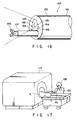
- Figs. 13 to 15 show the schematic structure of the
light source device 74 for the endoscope. When thelight source device 74 for endoscope is used in the vicinity of themagnet 77 of the MRI apparatus, adischarge lamp 81, which is built in thelight source device 74, is largely influenced by the static magnetic field. Thedischarge lamp 81 generates an arc discharge between the electrodes (not shown) and the discharge arc easily receives the influence of the magnetic field, and the arc is distorted in the magnetic field. - Therefore, by depending on a relative direction between the magnetic field, which is generated by the
magnet 73 of the MRI apparatus and anoptical axis 82, which connects aconnector 80, which corresponds to an injection inlet of thelight source device 74, to thedischarge lamp 81, thedischarge lamp 81 is not turned on, or thedischarge lamp 81 is turned on as the arc of thedischarge lamp 81 is distorted. Due to this, the outer temperature of thelamp 81 increases, and thelamp 81 may be broken. - The relative direction between the
optical axis 82 of thedischarge lamp 81 and the magnetic field is largely divided into three. More specifically, if the direction of the magnetic field, which is generated by the magnet, is set as shown by anarrow 83 or anarrow 84 in the figure, the discharge arc of thedischarge lamp 81 is distorted, and the above-mentioned disadvantages occur. On the other hand, if the direction of the magnetic field, which is generated b themagnet 73, is set as shown by anarrow 85, the lamp can be normally turned on under the strong magnetic field since the discharge arc is not distributed in upper and lower directions to right and left directions between the electrodes. Therefore, if the direction of theoptical axis 82 of thedischarge lamp 81 is consistent with the direction of the magnetic field, the discharge lamp can be normally turned on under even strong magnetic field. - Fig. 14 is one example showing the direction of the arrangement of the
light source device 74 in the vicinity of themagnet 73 of the MRI apparatus in view of the above-mentioned characteristic. In order to make the direction of the magnetic field and that of thelight axis 82 of thedischarge lamp 81 parallel to each other, the axis of themagnet 73 is set to be orthogonal or perpendicular to the front panel of thelight source device 74 to the rear panel. In Fig. 14, thelight source device 74 is arranged before abed 86 connected to themagnet 73. However, in consideration of the direction of the magnetic flux and that of thelight source device 74, it is possible to arrange thelight source device 74 at the position other than the position shown in the figure. - Fig. 15 is a block diagram showing the schematic structure of the
light source device 74. More specifically, alighting circuit 88 for lighting thedischarge lamp 81 is connected to apower source circuit 89 for generating a lighting signal and alighting signal generator 90, and controlled by a signal sent from a lighting/non-lighting discriminator 91. In the vicinity of thedischarge lamp 81, a single or a plurality of magnetic flux detector, e.g., a flux direction/strength detector 92 including a hole element and/or a Wiegand wire is provided. The lighting/non-lighting discriminator 91 and a flux direction/strength display 93 are connected to the flux direction/strength detector 92. The lighting/non-lighting discriminator 91 is connected to a warning/announcingcircuit 94 in addition to thelighting signal generator 90. Moreover, a warning/announcingmeans 97 for warning/announcing by light and sound generated by a warninglamp 95 and awarning speaker 96 is connected to the warning/announcingcircuit 94. - Therefore, the magnetic flux close to the
discharge lamp 81 is divided into the strength of each directional component, and detected by the flux direction/strength detector 92. The detection signal is inputted to the flux direction/strength display 93, the strength of the magnetic flux of each direction is converted to density of magnetic flux and displayed, or the direction of the magnetic flux close to the lamp is displayed. - One output signal of the flux direction/
strength detector 92 is inputted to the lighting/non-lighting discriminator 91. The lighting/non-lighting discriminator 91 discriminates whether or not the magnetic field close to thedischarge lamp 81 generates lighting defectiveness of the lamp. If it is discriminated that no lighting defectiveness is generated, a light allowing signal is inputted to thelighting signal generator 90, and a lighting signal is generated, and inputted to the lighting circuit. Then, based on this signal, thelighting circuit 88 turns on thedischarge lamp 81. - If it is discriminated that no lighting defectiveness of the
discharge lamp 81 is generated by the lighting/non-lighting discriminator 91, a light prohibiting signal is inputted to thelighting signal generator 90, and no lighting signal is generated, and the start of the lighting of thedischarge lamp 38 is not performed. At the same time, the light prohibiting signal is outputted to the warning/announcingcircuit 94. Since strength of the magnetic field close to the lamp is high and lighting defectiveness is generated, the warning/announcingcircuit 94 announces that thelight source device 74 is in a light prohibiting state, and warns that the strength of the magnetic field, which has influence upon the lighting, is high. - In the
light source device 74, there is provided a protection function, which determines whether or not the magnetic flux, which passes through thedischarge lamp 81, influences the lamp lighting state, and which allows the lighting of thedischarge lamp 81 only in the case that thelight source device 74 is arranged in the direction that no lighting defectiveness occurs. - Therefore, in the case that it is announced that the
discharge lamp 81 cannot be lightened, the direction and position of the thelight source device 74 are adjusted again with reference to the strength of the magnetic field displayed on the display, thereby making it possible to obtain the light allowing state. Due to this, it is possible to safely and surely perform the examination using the endoscope. - As explained above, the parts of the respective peripheral units whose operations are influenced by magnetism is arranged in such a direction where influence of magnetism, which is generated by the nuclear magnetic resonance image apparatus, is reduced. Thereby, the various types of peripheral units, which are arranged close to the magnet of the nuclear magnetic resonance image apparatus, can be surely and normally operated even under the strong magnetic field, and safety of the patient, which is examined and treated, can be ensured.
- If the above-mentioned technical advantage can be obtained by the above-mentioned diagnostic system using the nuclear magnetic resonance phenomenon, there must be satisfied the need for performing the fine and accurate image diagnosis and examination of tissue of the living body to surely perform the diagnosis or the needs for performing the treatment against the portion of the disease, which is recognized by the image diagnosis, under the examination by the endoscope.
- However, the conventional treatment implement for the endoscope is normally formed of magnetic material. Due to this, if the treatment implement is inserted to the patient in the MRI apparatus, the treatment implement is attracted by the extremely strong static magnetic field of the magnet of the MRI apparatus, and danger is exerted on the patient. Moreover, the magnetic filed is largely disturbed by magnetism of the treatment implement, and the MR image is largely distorted, so that image-diagnosis cannot be performed.
- Fig. 16 shows a top end side of an
insertion section 101 of anendoscope 100 when an examination and treatment are performed by use of a treatment implement for endoscope under the examination by an endoscope.Reference numeral 102 is a top end portion provided in theinsertion section 101 of theendoscope 100, and an observationoptical system 103, an illuminationoptical system 104, aninjection nozzle 105, and achannel 106 for treatment implement are provided thereon. An implement 107 is inserted to thechannel 106 and is projected from thetop end portion 102, and treatment is performed within the endoscope observation filed of vision by use of forceps. - Fig. 17 shows a state that a medical expert inserts the
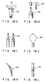
insertion section 101 of theendoscope 100 to thepatient 3 on anMRI apparatus 110, and examines the living body of the patient. Theendoscope 100 is formed of non-magnetic material in order to be used in strong magnetic field of theMRI apparatus 110. Moreover, on the top end portion of theinsertion section 101 of theendoscope 100, there is formed a high frequency coil for receiving an MR signal from a disease portion (Fig. 3 and Figs. 6 to 9), and the medical expert can MR-image-diagnose the disease portion while observing it through the endoscope. - Figs. 18A to 18L show a top end portion of each of various types of treatment implements for endoscope.
- Fig. 18A shows a
forceps 114 having a pair ofcups 113, which are freely opened and closed. Fig. 18B shows aforceps 116 having the pair ofcups 113 and aneedle 115. Fig. 18C shows abrush 119 for examining tissue, which is formed by putting abrush hair 118 on an inverse-U shapedwire 117. Fig. 18D shows abrush 122 for examining tissue, which is formed by putting abrush hair 121 on a rod-shape wire 120. - Fig. 18E shows a
crocodile holding forceps 124 having aforceps 123, which is freely opened and closed. Fig. 18F is a baskettype holding forceps 126 having abasket 125. Fig. 18G shows ascissors forceps 128 having a pair ofscissors 127. Fig. 18H is aclip device 130 having aclip 129. - Fig. 18I shows an
injection needle 131. Fig. 18J shows an ellipticalhigh frequency snare 132 for an electrical scalpel. Fig. 18K is a snare (papillotomy knife) 133 for an electrical scalpel to cut a duodenum and a papilla. Fig. 18L shows aheat probe 134. - Each of the above implements including the handy control section, insertion section, and top end mechanism, is formed of non-magnetic material. For example, plastic is used as the handy control section, a resin-made tube is used as a sheath, a non-magnetic metal such as phosphor bronze is used as a coil sheath, a tungsten wire is used as a wire, a titanium alloy is used as a top end portion, and copper or brass is used as other metallic parts, and a constant voltage diode is used as a heat element as shown in Fig. 18L.
- According to the above-structured treatment implement for endoscope, the treatment implement is not attracted even in the strong magnetic field of the magnet of the MRI apparatus 110 (Fig. 17). Therefore, the disease portion can be examined by the
endoscope 100, the MR diagnostic image of the disease portion can be formed, necessary treatments, examination of living body, and examination of tissue can be performed immediately under the examination by the endoscope. - In other words, according to the above-structured treatment implement for endoscope, since the treatment implement is formed of non-magnetic material, the treatment implement is not attracted by the extremely strong magnetic field of the magnet of the
MRI apparatus 110 even if it is inserted to thepatient 3 in theMRI apparatus 110, and no danger may be exerted on thepatient 3. - Since the treatment implement is non-magnetic, the magnetic field is not disturbed, and the MR image is not distorted, so that there can be obtained the technical advantage in which both fine and accurate image-diagnosis and the treatment using the endoscope can be performed.
- Figs. 18A to 18L show only a part of the examples of the treatment implements. If the other treatment implements are formed of non-magnetic material similar to the above embodiment, exactly the same technical advantage an be obtained. Therefore, the present invention is not limited to the treatment implements shown in the embodiment.
- In the above-mentioned diagnostic system, the insertion section, which has the flexible thin tube of the endoscope, is formed of non-magnetic material in order not to be attracted by the strong magnetic field of the magnet of the MRI apparatus and not to distort the MR image by disturbing the magnetic field.
- However, in the insertion section having the flexible thin tube such as the endoscope, it is difficult to structure a curved control section controlling a curved portion and a handy control section having an eye-piece by the non-magnetic member in view of processing and cost. To solve this problem, it is considered that the entire effective length of the insertion section is made longer not to be influenced by the magnetic field of the magnet, and the handy control section is used to be away from the magnet.
- In the actual use, the top end portion of the insertion section is inserted to the patient, and the scanning is performed by the MRI apparatus in a state that the handy control section is away from the magnet. However, the control section may be attracted by the magnetic field of the magnet during the scanning, and there may be occur a danger that the control section will collide with the patient.
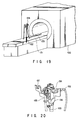
- Fig. 19 shows a
hanger 132 for endoscope, which is provided on abed 131 of theMRI apparatus 139, and which holds acontrol section 134 of anendoscope 133. - Fig. 20 shows a state that a
holding section 135 of thehunger 132 holds thecontrol section 134. Ahung section 136 and aswitch 137 are provided in theholding section 135. - The
hung section 136 is directed to hold thecontrol section 134 in order not to prevent thecontrol section section 134 from being attracted by magnetic force of the magnet. Theswitch 137 is provided to be turned on by thecontrol section 134 when thecontrol section 134 is correctly held by the holdingsection 135. Theswitch 137 is connected to allowing means (not shown) of theMRI apparatus 130. - In other words, the
control section 134 of theendoscope 133, which is inserted to the patient, is held by the holdingsection 135 of thehunger 132 when the scanning is performed by theMRI apparatus 130. At this time, if thecontrol section 134 is correctly held and protected from being attracted by the magnetic force of the magnet, allowing means of theMRI apparatus 130 allows the MRI apparatus to scan. That is, theMRI apparatus 130 can scan only when thecontrol section 134 of theendoscope 133 is held in a predetermined safe state. - Moreover, since the
control section 134 of theendoscope 133, which is formed of the non-magnetic member, is not attracted by the magnet when the scanning is performed by theMRI apparatus 130, safety against the patient can be extremely improved. Therefore, there can be obtain a technical advantage in which the safety against the patient can be ensured without increasing the manufacturing cost of theendoscope 133. - In addition, the same technical advantage can be also obtained by providing the
hunger 132 on atrolley 138 for endoscope, which is formed of non-magnetic material, as shown in Fig. 21, without providing it in thebed 131 of theMRI apparatus 130. Moreover, there can be obtained a technical advantage in which alight source device 139 for endoscope and aperipheral unit 140 can be contained in thetrolley 138, in addition to the prevention of the attraction of thecontrol section 134.
Claims (17)
- A diagnostic system using a nuclear magnetic resonance phenomenon comprising:
an external magnetic field generator (1), provided externally, for generating a magnetic field in a living body;
a thin diameter member (5) capable of inserting to a body cavity and having flexibility;
a high frequency coil (6), provided at a top end of said thin diameter member (5), for transmitting and receiving a high frequency; and
a nuclear magnetic resonance signal measuring device (2) for receiving a nuclear magnetic resonance signal from the living body characterized in that
insulating and separating means (12) is provided between said high frequency coil (6) and said nuclear magnetic resonance signal measuring device (2), for electrically insulating and separating both high frequency coil (6) and nuclear magnetic resonance signal measuring device (2) in a manner that the nuclear magnetic resonance signal is transmittable between said high frequency coil (6) and said nuclear magnetic resonance signal measuring device (2). - The system according to claim 1, characterized in that an amplifying means (9) is provided for amplifying the signal received by said high frequency coil (6).
- The system according to claim 2, characterized in that said insulating/separating means comprises a high frequency transducer (12) having a first wire connected to said nuclear magnetic resonance signal measuring device (2), and a second wire connected to an output side of said amplifying means (9) and electrically insulated from said first wire.
- The system according to claim 3, characterized in that a stabilizing d.c. power source (13) is provided for supplying a bias voltage to said amplifying means (9).
- The system according to claim 2, characterized in that said amplifying means (9) has a pre-amplifier (9), and said insulating and separating means has an isolation amplifier (14) provided between said pre-amplifier (9) and said nuclear magnetic resonance signal measuring device (2).
- The system according to claim 5, characterized in that a stabilizing d.c. power source (13) is provided for supplying a bias voltage to said pre-amplifier (9) and said isolation amplifier (14).
- The system according to claim 1, characterized in that said thin diameter member is an endoscope (5).
- A diagnostic system using a nuclear magnetic resonance phenomenon comprising:
a control section (31, 31a) internally provided;
an inserting section (32, 32a) of thin diameter, extended from said control section, capable of inserting to a body cavity and having flexibility;
an endoscope (21) having a high frequency antenna (56) provided in said insertion section; and
a plurality of magnetic resonance signal measuring devices (22) for processing a nuclear magnetic resonance signal from said high frequency antenna (56) characterized in that
matching means (57;58a, 58b, 58c) is provided for selectively making said high frequency antenna (56) connectable to each of said plurality of magnetic resonance signal measuring device (22) having a different circuit characteristic. - The system according to claim 8, characterized in that said antenna (56) is a loop antenna, and said matching means has a variable capacitor (66) connected to said antenna (56) in parallel and a variable capacitor (67) connected to said antenna (56) in series, and impedance-matches said antenna (56) and each of said magnetic resonance signal measuring device (22).
- The system according to claim 9, characterized in that said matching means has a diode (68) arranged in parallel to the loop antenna.
- The system according to claim 9, characterized in that adjusting means (60) is provided in said control section (31) to adjust the capacity of each of said variable capacitors (66, 67).
- The system according to claim 11, characterized in that said each of magnetic resonance signal measuring device (22) forms a signal showing a matching state between said matching means (57) and each of said magnetic resonance signal measuring device (22) when receiving each magnetic resonance signal from said antenna (56) through said matching means (57).
- The system according to claim 12, characterized in that an adjusting means controlling device (69) is provided to receive said signal showing the matching state, and to actuate said adjusting means (60) based on said signal.
- The system according to claim 8, characterized in that each of said matching means is connected to said antenna (56), and has a plurality of pre-amplifiers (38a, 38b, 38c) having a different circuit characteristic, and each of said pre-amplifiers is connectable to each of said magnetic resonance signal measuring devices (22) having a corresponding circuit characteristic.
- The system according to claim 14, characterized in that said endoscope (21) has a universal code (33a) extended from the controller (31a), and a signal line passage (37) extended to the universal code from said antenna (56).
- The system according to claim 15, characterized in that said endoscope (21) has a light guide (59), contained in the insertion section (32a), for illuminating an illumination light to a portion of an object to be examined from an end surface (52) of the insertion section, and an objective optical system (37) for image-forming light reflected from the portion of the object to be examined, and said light guide (50) is extended to said universal code (33a) from the insertion section (32).
- The system according to claim 16, characterized in that said endoscope (21) has an image-forming device (38), contained in the insertion section (32a), for converting the image image-formed by said objective optical system to an electrical signal, and a signal line passage (39) connected to said image-forming device at its one end, and extended to the inside portion between said insertion section (32a) and universal code (33a).
Priority Applications (1)
| Application Number | Priority Date | Filing Date | Title |
|---|---|---|---|
| EP96118785A EP0766093B1 (en) | 1992-06-25 | 1993-06-24 | Diagnostic system |
Applications Claiming Priority (6)
| Application Number | Priority Date | Filing Date | Title |
|---|---|---|---|
| JP4167627A JPH067319A (en) | 1992-06-25 | 1992-06-25 | Mr endoscopic system |
| JP167627/92 | 1992-06-25 | ||
| JP271850/92 | 1992-10-09 | ||
| JP27185092 | 1992-10-09 | ||
| JP28088/93 | 1993-02-17 | ||
| JP5028088A JPH06237918A (en) | 1993-02-17 | 1993-02-17 | Peripheral equipment for nmr video equipment |
Related Child Applications (1)
| Application Number | Title | Priority Date | Filing Date |
|---|---|---|---|
| EP96118785A Division EP0766093B1 (en) | 1992-06-25 | 1993-06-24 | Diagnostic system |
Publications (2)
| Publication Number | Publication Date |
|---|---|
| EP0576016A1 true EP0576016A1 (en) | 1993-12-29 |
| EP0576016B1 EP0576016B1 (en) | 1998-04-15 |
Family
ID=27286075
Family Applications (2)
| Application Number | Title | Priority Date | Filing Date |
|---|---|---|---|
| EP96118785A Expired - Lifetime EP0766093B1 (en) | 1992-06-25 | 1993-06-24 | Diagnostic system |
| EP93110132A Expired - Lifetime EP0576016B1 (en) | 1992-06-25 | 1993-06-24 | Diagnostic system using nuclear magnetic resonance phenomenon |
Family Applications Before (1)
| Application Number | Title | Priority Date | Filing Date |
|---|---|---|---|
| EP96118785A Expired - Lifetime EP0766093B1 (en) | 1992-06-25 | 1993-06-24 | Diagnostic system |
Country Status (3)
| Country | Link |
|---|---|
| US (1) | US5402788A (en) |
| EP (2) | EP0766093B1 (en) |
| DE (2) | DE69332985T2 (en) |
Cited By (1)
| Publication number | Priority date | Publication date | Assignee | Title |
|---|---|---|---|---|
| EP0672914A1 (en) * | 1994-03-18 | 1995-09-20 | Olympus Optical Co., Ltd. | Device for use in combination with a magnetic resonance imaging apparatus |
Families Citing this family (13)
| Publication number | Priority date | Publication date | Assignee | Title |
|---|---|---|---|---|
| JP3544557B2 (en) * | 1994-04-08 | 2004-07-21 | オリンパス株式会社 | Image file device |
| US5607441A (en) * | 1995-03-24 | 1997-03-04 | Ethicon Endo-Surgery, Inc. | Surgical dissector |
| AU7594798A (en) * | 1997-05-21 | 1998-12-11 | Cardiac M.R.I. Inc. | Cardiac mri with an internal receiving coil and an external receiving coil |
| JPH11275460A (en) * | 1998-03-24 | 1999-10-08 | Mitsubishi Electric Corp | Signal output circuit, signal input circuit and signal input/output circuit |
| US7286868B2 (en) * | 2001-06-15 | 2007-10-23 | Biosense Inc. | Medical device with position sensor having accuracy at high temperatures |
| US6496714B1 (en) * | 2001-07-20 | 2002-12-17 | Koninklijke Philips Electronics N.V. | RF-safe invasive device |
| US9482728B2 (en) * | 2006-12-29 | 2016-11-01 | The Johns Hopkins University | Methods, systems and devices for local magnetic resonance imaging |
| CN101657141B (en) * | 2007-02-26 | 2011-06-01 | 株式会社町田制作所 | Soft endoscope mirror for mri |
| US9259582B2 (en) | 2011-04-29 | 2016-02-16 | Cyberonics, Inc. | Slot antenna for an implantable device |
| US9240630B2 (en) | 2011-04-29 | 2016-01-19 | Cyberonics, Inc. | Antenna shield for an implantable medical device |
| US9089712B2 (en) | 2011-04-29 | 2015-07-28 | Cyberonics, Inc. | Implantable medical device without antenna feedthrough |
| US9265958B2 (en) | 2011-04-29 | 2016-02-23 | Cyberonics, Inc. | Implantable medical device antenna |
| EP2751585A1 (en) * | 2011-09-07 | 2014-07-09 | Koninklijke Philips N.V. | Dynamic modification of rf array coil/antenna impedance |
Citations (7)
| Publication number | Priority date | Publication date | Assignee | Title |
|---|---|---|---|---|
| EP0230168A1 (en) * | 1985-11-29 | 1987-07-29 | General Electric Cgr S.A. | Device and method for adjusting a radio frequency antenna in a nuclear magnetic resonance apparatus |
| US4737712A (en) * | 1986-12-31 | 1988-04-12 | General Electric Company | Isolated power transfer and patient monitoring system with interference rejection useful with NMR apparatus |
| US4951009A (en) * | 1989-08-11 | 1990-08-21 | Applied Materials, Inc. | Tuning method and control system for automatic matching network |
| EP0385367A1 (en) * | 1989-02-27 | 1990-09-05 | Medrad Inc. | Intracavity probe and interface device for MRI imaging and spectroscopy |
| US5035231A (en) * | 1987-04-27 | 1991-07-30 | Olympus Optical Co., Ltd. | Endoscope apparatus |
| US5050607A (en) * | 1987-03-04 | 1991-09-24 | Huntington Medical Research Institutes | High resolution magnetic resonance imaging of body cavities |
| US5143068A (en) * | 1990-11-26 | 1992-09-01 | Resonex, Inc. | Flexible and curved radio frequency (RF) coil for the human shoulder for magnetic resonance imaging apparatus |
Family Cites Families (16)
| Publication number | Priority date | Publication date | Assignee | Title |
|---|---|---|---|---|
| US4572198A (en) * | 1984-06-18 | 1986-02-25 | Varian Associates, Inc. | Catheter for use with NMR imaging systems |
| DE3429386A1 (en) * | 1984-08-09 | 1986-02-27 | Siemens AG, 1000 Berlin und 8000 München | MAIN SPIN TOMOGRAPHY UNIT |
| US4672972A (en) * | 1984-08-13 | 1987-06-16 | Berke Howard R | Solid state NMR probe |
| US4950993A (en) * | 1985-11-29 | 1990-08-21 | Thomson-Cgr | Device and method for adjusting a radiofrequency antenna of a nuclear magnetic resonance apparatus |
| US4960106A (en) * | 1987-04-28 | 1990-10-02 | Olympus Optical Co., Ltd. | Endoscope apparatus |
| US5170789A (en) * | 1987-06-17 | 1992-12-15 | Perinchery Narayan | Insertable NMR coil probe |
| US5348010A (en) * | 1989-02-24 | 1994-09-20 | Medrea, Inc., Pennsylvania Corp., Pa. | Intracavity probe and interface device for MRI imaging and spectroscopy |
| JPH035174A (en) * | 1989-06-02 | 1991-01-10 | Fujitsu Ltd | Horizontal printer |
| JP2921694B2 (en) * | 1990-01-17 | 1999-07-19 | オリンパス光学工業株式会社 | Magnetic resonance signal detection device |
| JP2566032B2 (en) * | 1990-02-06 | 1996-12-25 | オリンパス光学工業株式会社 | Endoscope |
| JPH0473051A (en) * | 1990-07-16 | 1992-03-09 | Olympus Optical Co Ltd | Detector for nmr |
| JPH04129533A (en) * | 1990-09-19 | 1992-04-30 | Toshiba Corp | Probe for mri device |
| US5188111A (en) * | 1991-01-18 | 1993-02-23 | Catheter Research, Inc. | Device for seeking an area of interest within a body |
| US5265610A (en) * | 1991-09-03 | 1993-11-30 | General Electric Company | Multi-planar X-ray fluoroscopy system using radiofrequency fields |
| US5307814A (en) * | 1991-09-17 | 1994-05-03 | Medrad, Inc. | Externally moveable intracavity probe for MRI imaging and spectroscopy |
| US5271400A (en) * | 1992-04-01 | 1993-12-21 | General Electric Company | Tracking system to monitor the position and orientation of a device using magnetic resonance detection of a sample contained within the device |
-
1993
- 1993-06-21 US US08/080,224 patent/US5402788A/en not_active Expired - Fee Related
- 1993-06-24 DE DE69332985T patent/DE69332985T2/en not_active Expired - Fee Related
- 1993-06-24 EP EP96118785A patent/EP0766093B1/en not_active Expired - Lifetime
- 1993-06-24 EP EP93110132A patent/EP0576016B1/en not_active Expired - Lifetime
- 1993-06-24 DE DE69317943T patent/DE69317943T2/en not_active Expired - Fee Related
Patent Citations (7)
| Publication number | Priority date | Publication date | Assignee | Title |
|---|---|---|---|---|
| EP0230168A1 (en) * | 1985-11-29 | 1987-07-29 | General Electric Cgr S.A. | Device and method for adjusting a radio frequency antenna in a nuclear magnetic resonance apparatus |
| US4737712A (en) * | 1986-12-31 | 1988-04-12 | General Electric Company | Isolated power transfer and patient monitoring system with interference rejection useful with NMR apparatus |
| US5050607A (en) * | 1987-03-04 | 1991-09-24 | Huntington Medical Research Institutes | High resolution magnetic resonance imaging of body cavities |
| US5035231A (en) * | 1987-04-27 | 1991-07-30 | Olympus Optical Co., Ltd. | Endoscope apparatus |
| EP0385367A1 (en) * | 1989-02-27 | 1990-09-05 | Medrad Inc. | Intracavity probe and interface device for MRI imaging and spectroscopy |
| US4951009A (en) * | 1989-08-11 | 1990-08-21 | Applied Materials, Inc. | Tuning method and control system for automatic matching network |
| US5143068A (en) * | 1990-11-26 | 1992-09-01 | Resonex, Inc. | Flexible and curved radio frequency (RF) coil for the human shoulder for magnetic resonance imaging apparatus |
Cited By (2)
| Publication number | Priority date | Publication date | Assignee | Title |
|---|---|---|---|---|
| EP0672914A1 (en) * | 1994-03-18 | 1995-09-20 | Olympus Optical Co., Ltd. | Device for use in combination with a magnetic resonance imaging apparatus |
| US5738632A (en) * | 1994-03-18 | 1998-04-14 | Olympus Optical Co., Ltd. | Device for use in combination with a magnetic resonance imaging apparatus |
Also Published As
| Publication number | Publication date |
|---|---|
| DE69332985D1 (en) | 2003-06-18 |
| DE69317943T2 (en) | 1998-08-06 |
| US5402788A (en) | 1995-04-04 |
| DE69317943D1 (en) | 1998-05-20 |
| DE69332985T2 (en) | 2004-02-19 |
| EP0576016B1 (en) | 1998-04-15 |
| EP0766093B1 (en) | 2003-05-14 |
| EP0766093A1 (en) | 1997-04-02 |
Similar Documents
| Publication | Publication Date | Title |
|---|---|---|
| US5402788A (en) | Diagnostic system using nuclear magnetic resonance phenomenon | |
| EP0672914B1 (en) | Device for use in combination with a magnetic resonance imaging apparatus | |
| US5035231A (en) | Endoscope apparatus | |
| US5427103A (en) | MRI apparatus for receiving nuclear-magnetic resonance signals of a living body | |
| EP1731093B1 (en) | System for detecting position in examinee | |
| JP3260930B2 (en) | Endoscope insertion state detection device | |
| JP2006517416A (en) | Optical MRI catheter system | |
| WO2000062672A9 (en) | Methods for in vivo magnetic resonance imaging | |
| JPH09238924A (en) | Treating tool and medical compound diagnosis system with the treating tool | |
| US5550471A (en) | Antenna cable for a diagnostic magnetic resonance apparatus | |
| JP4028643B2 (en) | MR endoscope | |
| JP4036399B2 (en) | MRI endoscope and MRI RF coil | |
| JP2001190518A (en) | Magnetic resonance observing device | |
| JP2000262487A (en) | Mri device | |
| JPH03212262A (en) | Nuclear magnetic resonance(nmr) endoscope | |
| JP3244376B2 (en) | Magnetic resonance observation equipment | |
| JPH06261881A (en) | Nuclear magnetic resonance signal diagnostic device | |
| JP3234033B2 (en) | Magnetic resonance observation equipment | |
| JPH08126627A (en) | Medical diagnostic apparatus | |
| JP3234089B2 (en) | Magnetic resonance observation equipment | |
| JPH067319A (en) | Mr endoscopic system | |
| JPH10216072A (en) | Magnetic resonance observation device | |
| JPH10262945A (en) | Magnetic resonance observing device | |
| JP2566032B2 (en) | Endoscope | |
| JPS63275332A (en) | Endoscope |
Legal Events
| Date | Code | Title | Description |
|---|---|---|---|
| PUAI | Public reference made under article 153(3) epc to a published international application that has entered the european phase |
Free format text: ORIGINAL CODE: 0009012 |
|
| 17P | Request for examination filed |
Effective date: 19930624 |
|
| AK | Designated contracting states |
Kind code of ref document: A1 Designated state(s): DE FR GB NL |
|
| 17Q | First examination report despatched |
Effective date: 19960715 |
|
| GRAG | Despatch of communication of intention to grant |
Free format text: ORIGINAL CODE: EPIDOS AGRA |
|
| GRAG | Despatch of communication of intention to grant |
Free format text: ORIGINAL CODE: EPIDOS AGRA |
|
| GRAH | Despatch of communication of intention to grant a patent |
Free format text: ORIGINAL CODE: EPIDOS IGRA |
|
| GRAH | Despatch of communication of intention to grant a patent |
Free format text: ORIGINAL CODE: EPIDOS IGRA |
|
| GRAA | (expected) grant |
Free format text: ORIGINAL CODE: 0009210 |
|
| AK | Designated contracting states |
Kind code of ref document: B1 Designated state(s): DE FR GB NL |
|
| XX | Miscellaneous (additional remarks) |
Free format text: TEILANMELDUNG 96118785.3 EINGEREICHT AM 22/11/96. |
|
| REF | Corresponds to: |
Ref document number: 69317943 Country of ref document: DE Date of ref document: 19980520 |
|
| ET | Fr: translation filed | ||
| PLBE | No opposition filed within time limit |
Free format text: ORIGINAL CODE: 0009261 |
|
| STAA | Information on the status of an ep patent application or granted ep patent |
Free format text: STATUS: NO OPPOSITION FILED WITHIN TIME LIMIT |
|
| 26N | No opposition filed | ||
| REG | Reference to a national code |
Ref country code: GB Ref legal event code: IF02 |
|
| PGFP | Annual fee paid to national office [announced via postgrant information from national office to epo] |
Ref country code: FR Payment date: 20060608 Year of fee payment: 14 |
|
| PGFP | Annual fee paid to national office [announced via postgrant information from national office to epo] |
Ref country code: NL Payment date: 20060615 Year of fee payment: 14 |
|
| PGFP | Annual fee paid to national office [announced via postgrant information from national office to epo] |
Ref country code: GB Payment date: 20060621 Year of fee payment: 14 |
|
| PGFP | Annual fee paid to national office [announced via postgrant information from national office to epo] |
Ref country code: DE Payment date: 20060622 Year of fee payment: 14 |
|
| GBPC | Gb: european patent ceased through non-payment of renewal fee |
Effective date: 20070624 |
|
| NLV4 | Nl: lapsed or anulled due to non-payment of the annual fee |
Effective date: 20080101 |
|
| REG | Reference to a national code |
Ref country code: FR Ref legal event code: ST Effective date: 20080229 |
|
| PG25 | Lapsed in a contracting state [announced via postgrant information from national office to epo] |
Ref country code: NL Free format text: LAPSE BECAUSE OF NON-PAYMENT OF DUE FEES Effective date: 20080101 Ref country code: DE Free format text: LAPSE BECAUSE OF NON-PAYMENT OF DUE FEES Effective date: 20080101 |
|
| PG25 | Lapsed in a contracting state [announced via postgrant information from national office to epo] |
Ref country code: GB Free format text: LAPSE BECAUSE OF NON-PAYMENT OF DUE FEES Effective date: 20070624 |
|
| PG25 | Lapsed in a contracting state [announced via postgrant information from national office to epo] |
Ref country code: FR Free format text: LAPSE BECAUSE OF NON-PAYMENT OF DUE FEES Effective date: 20070702 |