EP0575698B1 - Liquid electrophotographic printer developer - Google Patents
Liquid electrophotographic printer developer Download PDFInfo
- Publication number
- EP0575698B1 EP0575698B1 EP93103991A EP93103991A EP0575698B1 EP 0575698 B1 EP0575698 B1 EP 0575698B1 EP 93103991 A EP93103991 A EP 93103991A EP 93103991 A EP93103991 A EP 93103991A EP 0575698 B1 EP0575698 B1 EP 0575698B1
- Authority
- EP
- European Patent Office
- Prior art keywords
- roller
- developer
- rigidizing
- toner
- photoconductor surface
- Prior art date
- Legal status (The legal status is an assumption and is not a legal conclusion. Google has not performed a legal analysis and makes no representation as to the accuracy of the status listed.)
- Expired - Lifetime
Links
Images


Classifications
-
- G—PHYSICS
- G03—PHOTOGRAPHY; CINEMATOGRAPHY; ANALOGOUS TECHNIQUES USING WAVES OTHER THAN OPTICAL WAVES; ELECTROGRAPHY; HOLOGRAPHY
- G03G—ELECTROGRAPHY; ELECTROPHOTOGRAPHY; MAGNETOGRAPHY
- G03G15/00—Apparatus for electrographic processes using a charge pattern
- G03G15/06—Apparatus for electrographic processes using a charge pattern for developing
- G03G15/10—Apparatus for electrographic processes using a charge pattern for developing using a liquid developer
- G03G15/101—Apparatus for electrographic processes using a charge pattern for developing using a liquid developer for wetting the recording material
- G03G15/102—Apparatus for electrographic processes using a charge pattern for developing using a liquid developer for wetting the recording material for differentially wetting the recording material
-
- G—PHYSICS
- G03—PHOTOGRAPHY; CINEMATOGRAPHY; ANALOGOUS TECHNIQUES USING WAVES OTHER THAN OPTICAL WAVES; ELECTROGRAPHY; HOLOGRAPHY
- G03G—ELECTROGRAPHY; ELECTROPHOTOGRAPHY; MAGNETOGRAPHY
- G03G15/00—Apparatus for electrographic processes using a charge pattern
- G03G15/06—Apparatus for electrographic processes using a charge pattern for developing
- G03G15/10—Apparatus for electrographic processes using a charge pattern for developing using a liquid developer
- G03G15/11—Removing excess liquid developer, e.g. by heat
Definitions
- This invention relates generally to image transfer technology, and more specifically to electrophotography.
- a latent image is created on the surface of an insulating, photo-conducting material by selectively exposing areas of the surface to light. A difference in electrostatic charge density is created between the areas on the surface exposed and unexposed to light.
- the visible image is developed by electrostatic toners containing pigment components dispersed in an insulating carrier liquid. The toners are selectively attracted to the photoconductor surface either exposed or unexposed to light, depending on the relative electrostatic charges of the photoconductor surface, development electrode and the toner.
- the photoconductor may be either positively or negatively charged, and the toner system similarly may contain negatively or positively charged particles.
- the preferred embodiment is that the photoconductor and toner have the same polarity.
- a sheet of paper or intermediate transfer medium is given an electrostatic charge opposite that of the toner and passed closed to the photoconductor surface, pulling the toner from the photoconductor surface onto the paper or intermediate medium still in the pattern of the image developed from the photoconductor surface.
- Thermal energy may also be used to assist transfer of the image to paper or intermediate transfer medium.
- a set of fuser rollers melts and fixes the toner in the paper, for the case where no thermal transfer is used, subsequent to direct transfer or indirect transfer when using an intermediate transfer medium, producing the printed image.
- liquid toners with pigment components and thermoplastic components dispersed in a liquid carrier medium, usually aliphatic hydrocarbon liquids.
- a liquid carrier medium usually aliphatic hydrocarbon liquids.
- the basic printing colors - yellow, magenta, cyan and black may be applied sequentially to a photoconductor surface, and from there to a sheet of paper or intermediate medium to produce a multi-colored image.
- liquid toners there is a need to remove the liquid carrier medium from the photoconductor surface after the toner has been applied to it. This way, the photoconductor surface will not transfer the liquid carrier to the paper or to the intermediate medium in the image transfer step(s). Also, this way the liquid carrier may be recovered for recycle and reuse in the developer system, providing economy in terms of printing supplies, and eliminating environmental and health concerns from disposal of excess liquid carrier medium.
- U. S. Patents Nos. 4,974,027 and 4,999,677 disclose a positively biased reverse roller followed by a negatively biased rigidizing roller followed by a squeegee roller, separate from the rigidizing roller, for removing excess carrier liquid from the image after rigidization. The charge on these rollers may be reversed if the charge on the toner is reversed.
- an intermediate transfer drum is downstream of the rigidizing roller for receiving the toner image from the photoconductor surface and transferring the image to a sheet of paper.
- My invention is a liquid electrophotographic laser printer developer which has a moveable photoconductor surface with a positively charged latent image on it.
- the photoconductor surface may be a drum-type cylinder, but preferably, the photoconductor surface is a flat, thin rotating loop-type belt of photoconductor material.
- a positively charged developer roller Slightly downstream of, adjacent to, or in direct contact with the liquid toner bath, in the direction of movement of the photoconductor surface, is a positively charged developer roller, the outer surface of which is also in close proximity (approximately 50-75 microns, or .002-.003 inches) to the outer bottom of the photoconductor surface, the developer roller being rotatable so that its outer surface moves in the opposite direction of movement of the photoconductor surface for removing excess toner and carrier material from the photoconductor surface.
- the charge on the outer surface of the developer roller is between about (+) 300-500 volts.
- the speed of the outer surface of the developer roller is about 3 times the speed of the photo-conductor surface.
- a positively charged rigidizing/squeegee roller Downstream from the developer roller, and in relatively close relationship to it, is a positively charged rigidizing/squeegee roller in contact with the outer bottom surface of the photoconductor surface.
- the rigidizing/squeegee roller is rotatable so that its outer surface moves in the same direction of movement of, and at the same speed as, the photoconductor surface for removing residual carrier material from the photoconductor surface.
- the rigidizing/squeegee roller is not driven, but instead rides with the movement of the photoconductor surface.
- the rigidizing ⁇ squeegee roller is made of a conductive rubber material with a resistivity of approximately 10 8 ohm-cm, and is maintained at about the same positive charge as the toner, about (+) 300-400 volts at the outer surface of the roller. Also, preferably, the rigidizing/squeegee roller is located so that its point of contact, or nip, with the photo-conductive surface is close to the closest point of contact, or nip, of the developer roller.
- the charge on the rigidizing/squeegee roller is able to repel and compact toner on the latent image of the photoconductor surface, and remove excess toner, as well as excess liquid carrier, from the photoconductor surface before the charge of the toner breaks down or dissipates.
- the distance between the nip of the rigidizing/squeegee roller and the nip of the developer roller is minimized for compactness and to minimize the time between toner deposition and rigidizing-squeegeeing of the image.
- Beneath the developer roller and the rigidizing/squeegee roller is a common wiping means in contact with both the developer roller and the rigidizing/-squeegee roller to clean and remove residual toner and liquid carrier material from both rollers.
- the common wiping means may be a scraper blade in contact with both rollers, but it is preferably a conductive, rubber foam wiper roller with a charge maintained at electrostatically less than the positive charge on the developer and rigidizing/squeegee rollers in order to attract residual, positively charged toner from both rollers.
- This recycle means will have a drain, reservoir and recycle pump which are all preferably separate from, or external to, a cartridge container for the liquid toner bath, developer roller, rigidizing/squeegee roller and common wiping means.
- four separate cartridges containing my liquid developer system are provided in series along the direction of movement of the photoconductor surface, one each for the colors yellow, magenta, cyan and black, in that order. This way, successive, different color images may be developed on the photoconductor surface, and transferred at one time to a sheet of paper or other intermediate medium, ultimately creating a multicolor printed image on the paper.
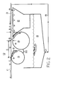
- Fig. 1 is a schematic diagram of one embodiment of the printer developer of my invention with the common wiping means being a rubber foam wiper roller.
- Fig. 2 is a schematic diagram of a different embodiment of my invention with the common wiping means being a scraper blade.
- Fig. 3 is a schematic diagram of an embodiment of my invention with four separate different color cartridges provided in series along the direction of movement of the photoconductor surface.
- Liquid toner bath 12 contains positively charged toner particles dispersed in a liquid carrier material.
- Toner bath 12 has open top surface 13 which is in close proximity to the photoconductor surface 11 for applying a thin film of toner to it.
- photoconductor surface 11 is a flat, thin rotating loop-type belt of photoconductor material.
- Organic, polymeric photoconductor materials are preferred, due to their economy.
- the photoconductor materials may contain an outer layer of photoconductive pigments dispersed in a binder material.
- the photoconductor outer surface may be overcoated with a low activation energy coating material, or the binder material itself may be a low activation energy material.
- the liquid toner is comprised of an insulating carrier liquid, "toner” particles, charge control agent, and additional additives as may be necessary to obtain desired image quality and image integrity.
- additives may, for example, include antistatic agents, plasticizer, leveling additives, dispersants, surfactants and other components added to the developer composition in order to improve the development and transfer characteristics of the toner.
- additives may be incorporated into either the toner particle or dissolved or dispersed in the carrier liquid.
- Such additives are known to those skilled in the art to which the invention pertains; however, this list of toner additives is provided for illustration, and is not intended to limit the scope of the invention.
- the carrier liquid may be selected from a wide variety of materials which are known in the art.
- the liquid is typically oleophilic, chemically stable under a variety of conditions, and electrically insulating.
- electrically insulating we mean that the liquid has a low dielectric constant and a high electrical resistivity.
- the carrier liquid has a dielectric constant of less than 5; more preferably less than 3.
- suitable carrier liquids include aliphatic hydrocarbons (n-pentane, hexane, heptane and the like), cycloaliphatic hydrocarbons (cyclopentane, cyclohexane and the like), aromatic hydrocarbons (benzene, toluene, xylene and the like), halogenated hydrocarbon solvents (chlorinated alkanes, fluorinated alkanes, chlorofluorocarbons and the like), silicone oils and blends of these solvents.
- aliphatic hydrocarbons n-pentane, hexane, heptane and the like
- cycloaliphatic hydrocarbons cyclopentane, cyclohexane and the like
- aromatic hydrocarbons benzene, toluene, xylene and the like
- halogenated hydrocarbon solvents chlorinated alkanes, fluorinated alkanes, chlorofluorocarbons and the like
- Preferred carrier liquids include paraffinic solvent blends sold under the names Isopar G, Isopar H, Isopar K and Isopar L (trademarks of Exxon Corporation); the most preferred carrier liquid is sold under the name Norpar 12 (trademark of Exxon Corporation).
- Isopar G paraffinic solvent blends sold under the names Isopar G, Isopar H, Isopar K and Isopar L
- Norpar 12 trademark of Exxon Corporation
- the toner particles are comprised of colorant embedded in a thermoplastic resin core.
- the colorant may be a dye or more preferably a pigment.
- the resin may be comprised of one or more polymers or copolymers which are characterized as being generally insoluble or only slightly soluble in the carrier liquid; these polymers or copolymers comprise a resin core.
- superior stability of the dispersed toner particles with respect to aggregation is obtained when at least one of the polymers or copolymers (denoted as the stabilizer) is an amphipathic substance containing at least one chain-like component of molecular weight at least 500 which is solvated by the carrier liquid.
- the selected stabilizer if present as an independent molecule, would have some finite solubility in the carrier liquid such that the carrier liquid is considerably better than a theta solvent as discussed in "Polymer Handbook” (Ed. Brandrup and Immergut, Interscience, 1966). Under such conditions, the stabilizer extends from the resin core into the carrier liquid, acting as a steric stabilizer as discussed in "Dispersion Polymerization” (Ed/Barrett, Interscience. 1975, p.9).
- the stabilizer may be chemically incorporated into the resin core (i.e. grafted to the core) or may be physically or chemically adsorbed to the core such that it remains as an integral part of the resin core.
- resin materials suitable for use in the liquid developer composition include polymers and copolymers of methyl acrylate, ethyl acrylate, butyl acrylate, ethylhexyl acrylate, lauryl acrylate, octadecyl acrylate, methyl(methacrylate), ethyl(methacrylate), lauryl methacrylate, hydroxy(ethylmethacrylate), octadecyl (methacrylate) and other polyacrylates.
- polymers may be used either alone or in conjunction with the aforementioned materials, including melamine and melamine formaldehyde resins, phenol formaldehyde resins, epoxy resins, polyester resins, styrene and styrene/acrylic copolymers, acrylic and methacrylic esters, cellulose acetate and cellulose acetate-butyrate copolymers, and poly(vinyl butyryl) copolymers.
- melamine and melamine formaldehyde resins phenol formaldehyde resins, epoxy resins, polyester resins, styrene and styrene/acrylic copolymers, acrylic and methacrylic esters, cellulose acetate and cellulose acetate-butyrate copolymers, and poly(vinyl butyryl) copolymers.
- melamine and melamine formaldehyde resins phenol formaldehyde resins
- epoxy resins epoxy resins
- polyester resins
- the colorants which may be used include virtually any dyes, stains or pigments which may be incorporated into the polymer resin, which are compatible with the carrier liquid, and which are useful and effective in making visible the latent electrostatic image.
- suitable colorants include: Phthalocyanine blue (C.I. Pigment Blue 15 and 16), Quinacridone magenta (D.I. Pigment Red 122, 192, 202 and 206), diarylide (benzidine) yellow (C.I. Pigment Yellow 12, 13, 14, 17, 55, 83 and 155) and arylamide (Hansa) yellow (C.I. Pigment Yellow 1, 3, 10, 73, 74, 97, 105 and 111); organic dyes, and black materials such as finely divided carbon and the like.
- Phthalocyanine blue C.I. Pigment Blue 15 and 16
- Quinacridone magenta D.I. Pigment Red 122, 192, 202 and 206
- diarylide (benzidine) yellow C.I. Pigment Yellow 12, 13, 14, 17,
- the optimal weight ratio of resin to colorant in the toner particles is on the order of 1/1 to 20/1, most preferably between 10/1 and 3/1.
- the total dispersed material in the carrier liquid typically represents 0.5 to 20 weight percent, most preferably between 0.5 and 3 weight percent of the total liquid developer composition.
- the developer composition includes a charge control agent, sometimes referred to as a charge director, to provide uniform charge polarity of the toner particles.
- the charge director may be incorporated into the toner particles, may be chemically reacted to the toner particle, may be chemically or physically adsorbed onto the toner particle (resin or pigment), and may be chelated to a functional group incorporated into the toner particle, preferably via a functional group comprising the stabilizer.
- the charge director acts to impart an electrical charge of selected polarity (either positive or negative) to the toner particles.
- Any number of charge directors described in the art may be used herein; preferred positive charge directors are the metallic soaps (U.S. Patent No. 3,411,936 to Kotsman et al.), most preferred are polyvalent metal soaps of zirconium and aluminum.
- toner bath top surface 13 is within about 50-75 microns (.002-.003 inches) from the bottom outer surface of photo-conductor surface 11. This distance is represented by letter “A” in the Figures. This way, an adequate supply of the positively charged toner is available to provide an ample film of the toner on the discharged areas of the photoconductor surface by means of an induced electrostatic attraction between them, due to the positive electrostatic bias of the developer roller.
- a positively biased developer roller 14 Slightly downstream of, adjacent to, or in direct contact with, the toner bath 12, in the direction of movement of the photoconductor surface 11, is a positively biased developer roller 14.
- the top outer surface of developer roller 14 is in close proximity to the bottom outer surface of the photoconductor surface 11.
- developer roller 14's top outer surface is within about 50-75 microns (.002-.003 inches) from the bottom outer surface of photoconductor surface 11. This distance is represented by letter “B” in the Figures.
- Developer roller 14 rotates in a direction opposite the movement of photoconductor surface 11. My studies confirm that the velocity of the outer surface of developer roller 14 should be about 3 times the velocity of the photoconductor surface. This way, a substantial shear force is exerted on the toner and carrier liquid film in the area of the nip of the developer roller 14, minimizing the film thickness of toner and carrier liquid on photoconductor surface 11 downstream of developer roller 14.
- the charge on the outer surface of developer roller 14 is maintained at between about (+) 400-500 volts. This way, the positive charge on the developer roller 14 repels the positive charge in the toner to the discharged areas of the photoconductor surface, and attracts toner in the charged areas of the photoconductor surface. This electrophoretic development minimizes toner in the background regions and maximizes toner deposition in the image areas.
- developer roller 14 has a diameter of 20-30mm.
- the smaller diameter roller is preferred in order to minimize the size of the developer system.
- the larger diameter roller is preferred in order to maximize the "effective footprint" size between the photoconductor surface and developer roller 14.
- the larger the "footprint" which is the region in which electrical fields are effective for deposition of toner, the more development time, and, consequently, the more dense the resultant image. Therefore, there is a trade-off in the selection of developer roller 14 diameter.
- a positively charged rigidizing/squeegee roller 15 in contact on its top outer surface with the photoconductor surface 11 is located downstream of the developer roller 14.
- I mean the rigidizing/squeegee roller 15 is pressed against the photoconductor surface 11, with a springed lever, for example. Due to fluid dynamic forces of the toner film on the photoconductor surface 11, I recognize there may be a slight physical separation, preferably less than about 1 micron, at the nip of the rigidizing/squeegee roller 15, represented by the letter “C” in the Figures.
- the rigidizing/squeegee roller 15 is rotatable in the same direction as movement of, and at the same speed as, the photoconductor surface 11.
- the rigidizing/squeegee roller 15 is not driven, but rides instead with the movement of the photoconductor surface 11. This way, the rigidizing/squeegee roller 15 does not tend to smear the latent image on photoconductor surface 11.
- the rigidizing/squeegee roller 15 is made of a conductive rubber material with a resistivity of about 10 8 Ohm-cm, and is maintained at about the same positive charge as the developer roller 14, between about (+) 300-500 volts at its outer surface.
- electrostatic repulsion prevents rigidizing/squeegee roller 15 from removing any image toner already bound to the discharged photoconductor surface 11, while the pressed contact of the roller with the photoconductor surface 11 permits "squeegee-ing" as much excess liquid carrier material from the photoconductor as possible.
- the rigidizing/squeegee roller 15 is located so that its nip is relatively close to the nip of developer roller 14.
- a rigidizing/squeegee roller 15 of 15mm diameter, a preferred size, and a developer roller 14 of 30mm diameter I prefer a distance between nips, represented as letter "D" in the Figures, of about 23mm. That is, the rollers 14 and 15 are almost touching.
- Distance "D” is preferably minimized to avoid the problem of charge breakdown or dissipation in the bound image toner, resulting in loss of image integrity. There is a time constant for this phenomena, and the latent image is compacted and rigidized best by the roller 15 when distance "D" is minimized.
- an easily “wettable” blade 21 lies near or in contact with rigidizing/squeegee roller 15 slightly upstream of nip point C.
- Blade 21 is of a generally planar shape, with an obtuse bend near its middle. It is generally vertically disposed, with its upper edge extending as close as possible, without contacting, nip point C. Its bottom edge extends down alongside the outer surface of rigidizing/squeegee roller 15, allowing excess toner to drain down along its top surface and into the space between rigidizing/squeegee roller 15 and developer roller 14. Blade 21 aids in removal of excess liquid toner from the region of nip point C.
- a common wiping means 16 or 20, in contact with both developer roller 14 and rigidizing/squeegee roller 15.
- the common wiping means being a rubber foam wiper roller 16.
- wiper roller 16 is an electrically conductive foam which is electrically biased relative to the toner at a level less than the developer roller 14 and the rigidizing/squeegee roller 15 in order to attract and remove toner from both rolls for redispersion in toner recycle reservoir 18.
- wiper roller 16 rotates so that its outer surface moves in the direction opposite the direction of movement of the outer surface of developer roller 14, and in the same direction as movement of the outer surface of rigidizing/squeegee roller 15. Also, preferably wiper roller 16 rotates so that the speed of its outer surface is different from the speed of developer roller 14's outer surface, and also different from the speed of rigidizing/squeegee roller 15's outer surface. This way, the speed differences at the nips between these rollers create shear forces which assist in cleaning and removing residual toner and carrier liquid from both developer roller 14 and rigidizing/squeegee 15.
- foam wiper roller 16 When foam wiper roller 16 is used, preferably a squeeze rod/roller is also used. Squeeze rod/roller lies parallel to the surface of, and is pressed firmly against, foam roller 16 for removal of toner and carrier liquid from it.
- the common wiping means may also be a scraper blade 20 in contact with both rollers as depicted in Fig. 2.
- Scraper blade 20 has drain means built into it for allowing removed toner and carrier liquid to drain into toner recycle reservoir 18.
- foam wiper roller 16 is preferred because it does not create "toner debris" which is an undesirable consequence of scraping.
- Beneath the photoconductor surface 11 and the rollers 14, 15 and 16, is a means for recycling toner and carrier liquid collected in reservoir 18 to the toner bath 12. This way, the excess toner and carrier liquid may be recovered and reused.
- this recycle means will have a drain 17 at the bottom of reservoir 18, and a pump in line 19 to collect and return the excess toner and carrier liquid to toner bath 12.
- the recycle means is external to the cartridge. This way, the cartridge may be compact, and conveniently changed out for repair or replacement.
- each developer cartridge contains toner for a different color - yellow, magenta, cyan and black, and they are provided in that order in the direction of movement of the photoconductor surface 11.
- This way, successive, different color latent images may be developed on the photoconductor surface 11, and transferred at one time to a sheet of paper or intermediate transfer medium, ultimately creating a multi-color printed image on the paper.
- overlapping different colors, or "overtoning" may be done, creating different colors and shades of different colors on the final printed image.
Description
- This invention relates generally to image transfer technology, and more specifically to electrophotography. I have invented a laser printer developer which may be used to produce multi-color images with liquid toners.
- In electrophotography, a latent image is created on the surface of an insulating, photo-conducting material by selectively exposing areas of the surface to light. A difference in electrostatic charge density is created between the areas on the surface exposed and unexposed to light. The visible image is developed by electrostatic toners containing pigment components dispersed in an insulating carrier liquid. The toners are selectively attracted to the photoconductor surface either exposed or unexposed to light, depending on the relative electrostatic charges of the photoconductor surface, development electrode and the toner. The photoconductor may be either positively or negatively charged, and the toner system similarly may contain negatively or positively charged particles. For laser printers, the preferred embodiment is that the photoconductor and toner have the same polarity.
- A sheet of paper or intermediate transfer medium is given an electrostatic charge opposite that of the toner and passed closed to the photoconductor surface, pulling the toner from the photoconductor surface onto the paper or intermediate medium still in the pattern of the image developed from the photoconductor surface. Thermal energy may also be used to assist transfer of the image to paper or intermediate transfer medium. A set of fuser rollers melts and fixes the toner in the paper, for the case where no thermal transfer is used, subsequent to direct transfer or indirect transfer when using an intermediate transfer medium, producing the printed image.
- There is a demand in the laser printer industry for multi-colored images. Responding to this demand, designers have turned to liquid toners, with pigment components and thermoplastic components dispersed in a liquid carrier medium, usually aliphatic hydrocarbon liquids. With liquid toners, it has been discovered, the basic printing colors - yellow, magenta, cyan and black, may be applied sequentially to a photoconductor surface, and from there to a sheet of paper or intermediate medium to produce a multi-colored image.
- With liquid toners, however, there is a need to remove the liquid carrier medium from the photoconductor surface after the toner has been applied to it. This way, the photoconductor surface will not transfer the liquid carrier to the paper or to the intermediate medium in the image transfer step(s). Also, this way the liquid carrier may be recovered for recycle and reuse in the developer system, providing economy in terms of printing supplies, and eliminating environmental and health concerns from disposal of excess liquid carrier medium.
- It is known from U.S. Patent No. 3,955,533 to employ a reverse direction roller spaced about 50 microns (1 micron = 1 µm) (about 0.002 inches) from the photoconductor surface to shear off the carrier liquid and excess pigmented solids in the region beyond the outer edge of the image to leave relatively clean background areas on the photoconductor surface.
- Also, from U. S. Patent No. 3,957,016, it is known in a negative toner system to use a positive biased reverse roller maintained at a voltage intermediate the image and background voltages to help clean the background and compact the image on the photoconductor surface.
- Also, from U. S. Patent No. 4,286,039, it is known in a positive toner system to use a reverse roller followed by a negatively biased squeegee roller. The squeegee roller both compacts the latent image and removes excess carrier liquid.
- U. S. Patents Nos. 4,974,027 and 4,999,677 disclose a positively biased reverse roller followed by a negatively biased rigidizing roller followed by a squeegee roller, separate from the rigidizing roller, for removing excess carrier liquid from the image after rigidization. The charge on these rollers may be reversed if the charge on the toner is reversed. In these two patents, an intermediate transfer drum is downstream of the rigidizing roller for receiving the toner image from the photoconductor surface and transferring the image to a sheet of paper.
- There is a need in the electrophotography industry then, for a liquid toner developer which provides a rigid latent image leaving the developer unit which is very dry and suitable for direct contact with the paper or intermediate transfer medium onto which the image will be transferred. Also, there is a need for a developer in which the developer roller and rigidizing or squeegee roller are in close proximity to provide a compact developer unit and to minimize any effect of electrostatic charge loss of the toner on the photoconductive surface between the two rollers. Also, there is a need to provide a liquid toner drain path along the length of the rigidizing/squeegee roller to aid excess toner removal from the roller. Also, there is a need for a developer in which the developer roller and rigidizing or squeegee roller are cleaned continuously of residual toner by a common cleaning means which is in contact with both the developer roller and the rigidizing or squeegee roller. Also, there is a need, if the common cleaning means above is a foam roller, for a squeeze rod/roller in contact with the foam roller for removal of toner and carrier liquid from it.
- My invention is a liquid electrophotographic laser printer developer which has a moveable photoconductor surface with a positively charged latent image on it. The photoconductor surface may be a drum-type cylinder, but preferably, the photoconductor surface is a flat, thin rotating loop-type belt of photoconductor material. There is a liquid toner bath containing positively charged toner particles dispersed in a liquid carrier material, the toner bath having an open top surface which is in close proximity (approximately 50-75 microns, or .002-.003 inches) to the outer bottom of the photoconductor surface for applying a thin film of toner to the photoconductor surface.
- Slightly downstream of, adjacent to, or in direct contact with the liquid toner bath, in the direction of movement of the photoconductor surface, is a positively charged developer roller, the outer surface of which is also in close proximity (approximately 50-75 microns, or .002-.003 inches) to the outer bottom of the photoconductor surface, the developer roller being rotatable so that its outer surface moves in the opposite direction of movement of the photoconductor surface for removing excess toner and carrier material from the photoconductor surface. Preferably, the charge on the outer surface of the developer roller is between about (+) 300-500 volts. Also, preferably, the speed of the outer surface of the developer roller is about 3 times the speed of the photo-conductor surface. Downstream from the developer roller, and in relatively close relationship to it, is a positively charged rigidizing/squeegee roller in contact with the outer bottom surface of the photoconductor surface. The rigidizing/squeegee roller is rotatable so that its outer surface moves in the same direction of movement of, and at the same speed as, the photoconductor surface for removing residual carrier material from the photoconductor surface. Preferably, the rigidizing/squeegee roller is not driven, but instead rides with the movement of the photoconductor surface. Also, preferably, the rigidizing\squeegee roller is made of a conductive rubber material with a resistivity of approximately 108 ohm-cm, and is maintained at about the same positive charge as the toner, about (+) 300-400 volts at the outer surface of the roller. Also, preferably, the rigidizing/squeegee roller is located so that its point of contact, or nip, with the photo-conductive surface is close to the closest point of contact, or nip, of the developer roller. This way, the charge on the rigidizing/squeegee roller is able to repel and compact toner on the latent image of the photoconductor surface, and remove excess toner, as well as excess liquid carrier, from the photoconductor surface before the charge of the toner breaks down or dissipates. Preferably, the distance between the nip of the rigidizing/squeegee roller and the nip of the developer roller is minimized for compactness and to minimize the time between toner deposition and rigidizing-squeegeeing of the image.
- Beneath the developer roller and the rigidizing/squeegee roller is a common wiping means in contact with both the developer roller and the rigidizing/-squeegee roller to clean and remove residual toner and liquid carrier material from both rollers. The common wiping means may be a scraper blade in contact with both rollers, but it is preferably a conductive, rubber foam wiper roller with a charge maintained at electrostatically less than the positive charge on the developer and rigidizing/squeegee rollers in order to attract residual, positively charged toner from both rollers.
- Finally, beneath the photoconductor surface and all the rollers is a means for recycling toner and liquid carrier material drained to the bottom of the system, or removed by the common wiper means, to the liquid bath. This recycle means will have a drain, reservoir and recycle pump which are all preferably separate from, or external to, a cartridge container for the liquid toner bath, developer roller, rigidizing/squeegee roller and common wiping means.
- In a preferred embodiment of my invention, four separate cartridges containing my liquid developer system are provided in series along the direction of movement of the photoconductor surface, one each for the colors yellow, magenta, cyan and black, in that order. This way, successive, different color images may be developed on the photoconductor surface, and transferred at one time to a sheet of paper or other intermediate medium, ultimately creating a multicolor printed image on the paper.
- Fig. 1 is a schematic diagram of one embodiment of the printer developer of my invention with the common wiping means being a rubber foam wiper roller.
- Fig. 2 is a schematic diagram of a different embodiment of my invention with the common wiping means being a scraper blade.
- Fig. 3 is a schematic diagram of an embodiment of my invention with four separate different color cartridges provided in series along the direction of movement of the photoconductor surface.
- Referring to the Figures, there is depicted generally my
printer developer 10 with movable photoconductor surface 11 with a positively charged latent image on it. The direction of movement of the photoconductor surface is indicated by the arrow.Liquid toner bath 12 contains positively charged toner particles dispersed in a liquid carrier material.Toner bath 12 hasopen top surface 13 which is in close proximity to the photoconductor surface 11 for applying a thin film of toner to it. Preferably, photoconductor surface 11 is a flat, thin rotating loop-type belt of photoconductor material. Organic, polymeric photoconductor materials are preferred, due to their economy. The photoconductor materials may contain an outer layer of photoconductive pigments dispersed in a binder material. The photoconductor outer surface may be overcoated with a low activation energy coating material, or the binder material itself may be a low activation energy material. - The liquid toner is comprised of an insulating carrier liquid, "toner" particles, charge control agent, and additional additives as may be necessary to obtain desired image quality and image integrity. Such additives may, for example, include antistatic agents, plasticizer, leveling additives, dispersants, surfactants and other components added to the developer composition in order to improve the development and transfer characteristics of the toner. These additives may be incorporated into either the toner particle or dissolved or dispersed in the carrier liquid. Such additives are known to those skilled in the art to which the invention pertains; however, this list of toner additives is provided for illustration, and is not intended to limit the scope of the invention.
- The carrier liquid may be selected from a wide variety of materials which are known in the art. The liquid is typically oleophilic, chemically stable under a variety of conditions, and electrically insulating. By electrically insulating we mean that the liquid has a low dielectric constant and a high electrical resistivity. Preferably, the carrier liquid has a dielectric constant of less than 5; more preferably less than 3. Examples of suitable carrier liquids include aliphatic hydrocarbons (n-pentane, hexane, heptane and the like), cycloaliphatic hydrocarbons (cyclopentane, cyclohexane and the like), aromatic hydrocarbons (benzene, toluene, xylene and the like), halogenated hydrocarbon solvents (chlorinated alkanes, fluorinated alkanes, chlorofluorocarbons and the like), silicone oils and blends of these solvents. Preferred carrier liquids include paraffinic solvent blends sold under the names Isopar G, Isopar H, Isopar K and Isopar L (trademarks of Exxon Corporation); the most preferred carrier liquid is sold under the name Norpar 12 (trademark of Exxon Corporation). The foregoing list is intended as merely illustrative of the carrier liquids which may be used in conjunction with the present invention, and is not in any way intended to limit the scope of this invention.
- The toner particles are comprised of colorant embedded in a thermoplastic resin core. The colorant may be a dye or more preferably a pigment. The resin may be comprised of one or more polymers or copolymers which are characterized as being generally insoluble or only slightly soluble in the carrier liquid; these polymers or copolymers comprise a resin core. In addition, superior stability of the dispersed toner particles with respect to aggregation is obtained when at least one of the polymers or copolymers (denoted as the stabilizer) is an amphipathic substance containing at least one chain-like component of molecular weight at least 500 which is solvated by the carrier liquid. By this we mean that the selected stabilizer, if present as an independent molecule, would have some finite solubility in the carrier liquid such that the carrier liquid is considerably better than a theta solvent as discussed in "Polymer Handbook" (Ed. Brandrup and Immergut, Interscience, 1966). Under such conditions, the stabilizer extends from the resin core into the carrier liquid, acting as a steric stabilizer as discussed in "Dispersion Polymerization" (Ed/Barrett, Interscience. 1975, p.9). The stabilizer may be chemically incorporated into the resin core (i.e. grafted to the core) or may be physically or chemically adsorbed to the core such that it remains as an integral part of the resin core.
- Examples of resin materials suitable for use in the liquid developer composition include polymers and copolymers of methyl acrylate, ethyl acrylate, butyl acrylate, ethylhexyl acrylate, lauryl acrylate, octadecyl acrylate, methyl(methacrylate), ethyl(methacrylate), lauryl methacrylate, hydroxy(ethylmethacrylate), octadecyl (methacrylate) and other polyacrylates. Other polymers may be used either alone or in conjunction with the aforementioned materials, including melamine and melamine formaldehyde resins, phenol formaldehyde resins, epoxy resins, polyester resins, styrene and styrene/acrylic copolymers, acrylic and methacrylic esters, cellulose acetate and cellulose acetate-butyrate copolymers, and poly(vinyl butyryl) copolymers. The foregoing list is intended as merely illustrative of the polymers and copolymers comprising toner particles which may be used in conjunction with the present invention, and is not in any way intended to limit the scope of this invention.
- The colorants which may be used include virtually any dyes, stains or pigments which may be incorporated into the polymer resin, which are compatible with the carrier liquid, and which are useful and effective in making visible the latent electrostatic image. Examples of suitable colorants include: Phthalocyanine blue (C.I.
Pigment Blue 15 and 16), Quinacridone magenta (D.I. Pigment Red 122, 192, 202 and 206), diarylide (benzidine) yellow (C.I. Pigment Yellow 12, 13, 14, 17, 55, 83 and 155) and arylamide (Hansa) yellow (C.I.Pigment Yellow 1, 3, 10, 73, 74, 97, 105 and 111); organic dyes, and black materials such as finely divided carbon and the like. The foregoing list is intended as merely illustrative of the colorants incorporated into toner particles which may be used in conjunction with the present invention, and is not in any way intended to limit the scope of this invention. - The optimal weight ratio of resin to colorant in the toner particles is on the order of 1/1 to 20/1, most preferably between 10/1 and 3/1. The total dispersed material in the carrier liquid typically represents 0.5 to 20 weight percent, most preferably between 0.5 and 3 weight percent of the total liquid developer composition.
- The developer composition includes a charge control agent, sometimes referred to as a charge director, to provide uniform charge polarity of the toner particles. The charge director may be incorporated into the toner particles, may be chemically reacted to the toner particle, may be chemically or physically adsorbed onto the toner particle (resin or pigment), and may be chelated to a functional group incorporated into the toner particle, preferably via a functional group comprising the stabilizer. The charge director acts to impart an electrical charge of selected polarity (either positive or negative) to the toner particles. Any number of charge directors described in the art may be used herein; preferred positive charge directors are the metallic soaps (U.S. Patent No. 3,411,936 to Kotsman et al.), most preferred are polyvalent metal soaps of zirconium and aluminum.
- Preferably, toner bath
top surface 13 is within about 50-75 microns (.002-.003 inches) from the bottom outer surface of photo-conductor surface 11. This distance is represented by letter "A" in the Figures. This way, an adequate supply of the positively charged toner is available to provide an ample film of the toner on the discharged areas of the photoconductor surface by means of an induced electrostatic attraction between them, due to the positive electrostatic bias of the developer roller. - Slightly downstream of, adjacent to, or in direct contact with, the
toner bath 12, in the direction of movement of the photoconductor surface 11, is a positivelybiased developer roller 14. The top outer surface ofdeveloper roller 14 is in close proximity to the bottom outer surface of the photoconductor surface 11. Preferably,developer roller 14's top outer surface is within about 50-75 microns (.002-.003 inches) from the bottom outer surface of photoconductor surface 11. This distance is represented by letter "B" in the Figures.Developer roller 14 rotates in a direction opposite the movement of photoconductor surface 11. My studies confirm that the velocity of the outer surface ofdeveloper roller 14 should be about 3 times the velocity of the photoconductor surface. This way, a substantial shear force is exerted on the toner and carrier liquid film in the area of the nip of thedeveloper roller 14, minimizing the film thickness of toner and carrier liquid on photoconductor surface 11 downstream ofdeveloper roller 14. - Also, the charge on the outer surface of
developer roller 14 is maintained at between about (+) 400-500 volts. This way, the positive charge on thedeveloper roller 14 repels the positive charge in the toner to the discharged areas of the photoconductor surface, and attracts toner in the charged areas of the photoconductor surface. This electrophoretic development minimizes toner in the background regions and maximizes toner deposition in the image areas. - Preferably,
developer roller 14 has a diameter of 20-30mm. The smaller diameter roller is preferred in order to minimize the size of the developer system. However, the larger diameter roller is preferred in order to maximize the "effective footprint" size between the photoconductor surface anddeveloper roller 14. The larger the "footprint", which is the region in which electrical fields are effective for deposition of toner, the more development time, and, consequently, the more dense the resultant image. Therefore, there is a trade-off in the selection ofdeveloper roller 14 diameter. - A positively charged rigidizing/
squeegee roller 15 in contact on its top outer surface with the photoconductor surface 11 is located downstream of thedeveloper roller 14. By "in contact with", I mean the rigidizing/squeegee roller 15 is pressed against the photoconductor surface 11, with a springed lever, for example. Due to fluid dynamic forces of the toner film on the photoconductor surface 11, I recognize there may be a slight physical separation, preferably less than about 1 micron, at the nip of the rigidizing/squeegee roller 15, represented by the letter "C" in the Figures. The rigidizing/squeegee roller 15 is rotatable in the same direction as movement of, and at the same speed as, the photoconductor surface 11. Preferably, the rigidizing/squeegee roller 15 is not driven, but rides instead with the movement of the photoconductor surface 11. This way, the rigidizing/squeegee roller 15 does not tend to smear the latent image on photoconductor surface 11. - Preferably, the rigidizing/
squeegee roller 15 is made of a conductive rubber material with a resistivity of about 108 Ohm-cm, and is maintained at about the same positive charge as thedeveloper roller 14, between about (+) 300-500 volts at its outer surface. This way, electrostatic repulsion prevents rigidizing/squeegee roller 15 from removing any image toner already bound to the discharged photoconductor surface 11, while the pressed contact of the roller with the photoconductor surface 11 permits "squeegee-ing" as much excess liquid carrier material from the photoconductor as possible. - Also preferably, the rigidizing/
squeegee roller 15 is located so that its nip is relatively close to the nip ofdeveloper roller 14. For a rigidizing/squeegee roller 15 of 15mm diameter, a preferred size, and adeveloper roller 14 of 30mm diameter, I prefer a distance between nips, represented as letter "D" in the Figures, of about 23mm. That is, therollers roller 15 when distance "D" is minimized. - Optionally, an easily "wettable"
blade 21 lies near or in contact with rigidizing/squeegee roller 15 slightly upstream of nippoint C. Blade 21 is of a generally planar shape, with an obtuse bend near its middle. It is generally vertically disposed, with its upper edge extending as close as possible, without contacting, nip point C. Its bottom edge extends down alongside the outer surface of rigidizing/squeegee roller 15, allowing excess toner to drain down along its top surface and into the space between rigidizing/squeegee roller 15 anddeveloper roller 14.Blade 21 aids in removal of excess liquid toner from the region of nip point C. If the film of liquid toner on the photoconductor surface is more than about 1 micron thick downstream of the nip point B ofdeveloper roller 14, then excess toner builds up, or "floods" at nip point C. At "flood" conditions, excess toner travels to the ends of rigidizing/squeegee roller 15, and at the longitudinal boundaries of the roller, wicks across the nip point C of the roller and becomes deposited on the photoconductor surface downstream of the nip point C, eliminating the benefit of the rigidizing/squeegee roller.Optional blade 21 helps prevent "flood" conditions by providing a convenient drain path along the length of rigidizing/squeegee roller 15. - Beneath the
developer roller 14 and the rigidizing/squeegee roller 15 is a common wiping means, 16 or 20, in contact with bothdeveloper roller 14 and rigidizing/squeegee roller 15. In Fig. 1 there is depicted an embodiment of my invention with the common wiping means being a rubberfoam wiper roller 16. Preferably,wiper roller 16 is an electrically conductive foam which is electrically biased relative to the toner at a level less than thedeveloper roller 14 and the rigidizing/squeegee roller 15 in order to attract and remove toner from both rolls for redispersion intoner recycle reservoir 18. - Preferably,
wiper roller 16 rotates so that its outer surface moves in the direction opposite the direction of movement of the outer surface ofdeveloper roller 14, and in the same direction as movement of the outer surface of rigidizing/squeegee roller 15. Also, preferablywiper roller 16 rotates so that the speed of its outer surface is different from the speed ofdeveloper roller 14's outer surface, and also different from the speed of rigidizing/squeegee roller 15's outer surface. This way, the speed differences at the nips between these rollers create shear forces which assist in cleaning and removing residual toner and carrier liquid from bothdeveloper roller 14 and rigidizing/squeegee 15. - When
foam wiper roller 16 is used, preferably a squeeze rod/roller is also used. Squeeze rod/roller lies parallel to the surface of, and is pressed firmly against,foam roller 16 for removal of toner and carrier liquid from it. - The common wiping means may also be a
scraper blade 20 in contact with both rollers as depicted in Fig. 2.Scraper blade 20 has drain means built into it for allowing removed toner and carrier liquid to drain intotoner recycle reservoir 18. However,foam wiper roller 16 is preferred because it does not create "toner debris" which is an undesirable consequence of scraping. - Beneath the photoconductor surface 11 and the
rollers reservoir 18 to thetoner bath 12. This way, the excess toner and carrier liquid may be recovered and reused. Generally, this recycle means will have adrain 17 at the bottom ofreservoir 18, and a pump inline 19 to collect and return the excess toner and carrier liquid totoner bath 12. Preferably, when my developer system is manufactured and assembled in a cartridge format for thetoner bath 12,developer roller 14, rigidizing/squeegee roller 15 andwiper roller 16 orscraper 20, the recycle means is external to the cartridge. This way, the cartridge may be compact, and conveniently changed out for repair or replacement. - In a preferred embodiment of my invention, depicted schematically in Fig. 3, four separate cartridges 31-34 containing my developer system are provided in series along the direction of movement of the photoconductor surface 11. Each developer cartridge contains toner for a different color - yellow, magenta, cyan and black, and they are provided in that order in the direction of movement of the photoconductor surface 11. This way, successive, different color latent images may be developed on the photoconductor surface 11, and transferred at one time to a sheet of paper or intermediate transfer medium, ultimately creating a multi-color printed image on the paper. Also, overlapping different colors, or "overtoning" may be done, creating different colors and shades of different colors on the final printed image. With my developer system, a very dry latent image is created on the photoconductor surface, allowing subsequent, successive latent images of different colors and even overtoning of two colors. Also, with my developer system the latent image may be directly transferred to paper, or to an intermediate medium and then to paper without concern of excessive carrier liquid carry-out by the paper. Also, with my developer system there is no need to provide a separate, external dryer for removing excess carrier liquid.
- While there is shown and described the present preferred embodiment of the invention, it is to be distinctly understood that this invention is not limited thereto but may be variously embodied to practice within the scope of the following claims.
Claims (10)
- A liquid electrophotographic printer developer system (10) comprising:- a moveable, photoconductor surface (11) with an outer bottom surface having a positively charged latent image on it, said outer bottom surface moving in a first direction at a first speed;- a liquid toner bath (12) containing positively charged toner particles dispersed in a liquid carrier material, said liquid toner bath (12) having an open top surface (13) which is beneath and within about 50 to 75 micrometers from the outer bottom of said photoconductor surface (11), for applying toner to said photoconductor surface (11);- a positively charged developer roller (14) with an outer surface, said developer roller being slightly downstream of said liquid toner bath (12) in said first direction of movement of said photoconductor surface (11), and adjacent to said liquid toner bath (12), the outer surface of said developer roller (14) also being beneath and in close proximity to the outer bottom of said photoconductor surface (11), said developer roller (14) being rotatable in a second direction opposite to said first direction of movement of said photoconductor surface (11) at a second speed for removing excess toner particles and liquid carrier material from said photoconductor surface (11);- a positively charged rigidizing/squeegee roller (15) with an outer surface, said rigidizing/squeegee roller (15) being downstream from said developer roller (14) and in relatively close spaced-apart relationship from it, the outer surface of said riqidizing/squeegee roller (15) being beneath and in contact with the outer bottom surface of said photoconductor surface (11), said rigidizing/squeegee roller (15) being rotatable in the same said first direction of movement of, and at the same said first speed as said photoconductor surface (11), for removing residual liquid carrier material from said photoconductor surface (11);- a common wiping means (16, 20), in contact with both said developer roller (14) and said rigidizing/squeegee roller (15) to remove residual toner and liquid carrier material from said developer roller (14) and said rigidizing/squeegee roller (15); and- a recycle means (17, 19) beneath said photoconductor surface (11), said developer roller (14) and said rigidizing/squeegee roller (15) and said common wiping means (16, 20) for receiving excess toner and liquid carrier material for recycling toner and liquid carrier material to said liquid toner bath (12).
- The developer system of Claim 1 wherein the open top surface (13) of said liquid toner bath (12) is approximately 50 micrometers from the bottom outer surface of said photoconductor surface (11).
- The developer system of Claim 1 wherein the outer surface of said developer roller (14) is approximately 50 micrometers from the bottom outer surface of said photoconductor surface (11).
- The developer system of Claim 1 wherein the charge on the outer surface of said developer roller (14) is from about 400 to about 500 volts.
- The developer system of Claim 1 wherein said rigidizing/squeegee roller (15) is made of a conductive rubber material with a restivity of about 108 Ohm-cm.
- The developer system of Claim 1 wherein the outer surface of said rigidizing/squeegee roller (15) has a positive charge which is from about 300 to about 500 volts.
- The developer system of Claim 1 wherein a blade (21) lies close to the outer surface of said rigidizing/squeegee roller (15), slightly upstream of its nip point, to produce a drain path along the outer surface of said rigidizing/squeegee roller (15) to aid excess toner removal from said rigidizing/squeegee roller (15).
- The developer system of Claim 1 wherein said common wiping means is a scraper blade (20) in contact with both said developer roller (14) and said rigidizing/squeegee roller (15).
- The developer system of Claim 1 wherein said common wiping means is a conductive, foam wiper roller (16) in contact with both said developer roller (14) and said rigidizing/squeegee roller (15).
- The developer system of Claim 1 wherein a plurality of separate cartridges (31, 32, 33, 34) containing said liquid toner bath (12), said developer roller (14), said rigidizing/squeegee roller (15), said common wiping means (16, 20) and recycle means (17, 19) are provided in series along the direction of movement of said photoconductor surface (11).
Applications Claiming Priority (2)
| Application Number | Priority Date | Filing Date | Title |
|---|---|---|---|
| US07/904,798 US5300990A (en) | 1992-06-26 | 1992-06-26 | Liquid electrophotographic printer developer |
| US904798 | 1992-06-26 |
Publications (3)
| Publication Number | Publication Date |
|---|---|
| EP0575698A2 EP0575698A2 (en) | 1993-12-29 |
| EP0575698A3 EP0575698A3 (en) | 1994-10-05 |
| EP0575698B1 true EP0575698B1 (en) | 1997-01-08 |
Family
ID=25419803
Family Applications (1)
| Application Number | Title | Priority Date | Filing Date |
|---|---|---|---|
| EP93103991A Expired - Lifetime EP0575698B1 (en) | 1992-06-26 | 1993-03-11 | Liquid electrophotographic printer developer |
Country Status (4)
| Country | Link |
|---|---|
| US (1) | US5300990A (en) |
| EP (1) | EP0575698B1 (en) |
| JP (1) | JP3352771B2 (en) |
| DE (1) | DE69307195T2 (en) |
Families Citing this family (42)
| Publication number | Priority date | Publication date | Assignee | Title |
|---|---|---|---|---|
| US5432591A (en) * | 1994-02-07 | 1995-07-11 | Hewlett-Packard Company | Multi-purpose foam roller in a liquid toner developer |
| WO1996002024A1 (en) * | 1994-07-07 | 1996-01-25 | Toray Industries, Inc. | Recording apparatus and recording method |
| US5539504A (en) * | 1995-02-02 | 1996-07-23 | Hewlett-Packard Company | Liquid toner extraction apparatus for electrophotographic equipment |
| US5666615A (en) * | 1995-02-03 | 1997-09-09 | Hewlett-Packard Company | Minimal liquid carrier transfer in an image formation process |
| US5557377A (en) * | 1995-05-30 | 1996-09-17 | Hewlett-Packard Company | Single pass, in-line color electrophotographic printer with interspersed erase device |
| US5519473A (en) * | 1995-07-03 | 1996-05-21 | Xerox Corporation | Liquid developing material applicator |
| KR19990063863A (en) * | 1995-09-29 | 1999-07-26 | 스프레이그 로버트 월터 | Compression apparatus and method for removing developer from an imaging substrate |
| KR19990063859A (en) * | 1995-09-29 | 1999-07-26 | 스프레이그 로버트 월터 | Apparatus for removing back plate developer from developer |
| US5596398A (en) * | 1995-09-29 | 1997-01-21 | Minnesota Mining & Manufacturing Company | Apparatus and method for cleaning developer from an imaging substrate |
| WO1997012288A1 (en) * | 1995-09-29 | 1997-04-03 | Minnesota Mining And Manufacturing Company | Method and apparatus for producing a multi-colored image in an electrophotographic system |
| KR19990063858A (en) * | 1995-09-29 | 1999-07-26 | 스프레이그 로버트 월터 | Apparatus and method for removing developer liquid from an image forming substrate |
| US6091918A (en) * | 1995-09-29 | 2000-07-18 | Minnesota Mining And Manufacturing Company | Squeegee apparatus and method for removing developer liquid from an imaging substrate |
| US5576815A (en) * | 1995-09-29 | 1996-11-19 | Minnesota Mining And Manufacturing Company | Development apparatus for a liquid electrographic imaging system |
| WO1997012291A1 (en) * | 1995-09-29 | 1997-04-03 | Minnesota Mining And Manufacturing Company | Apparatus and method for removing developer liquid from an imaging substrate |
| CN1087692C (en) * | 1995-10-30 | 2002-07-17 | 新日本制铁株式会社 | Electrostatic recorder |
| US5832342A (en) * | 1996-07-25 | 1998-11-03 | Mita Industrial Co., Ltd. | Image forming machine with a contact type developing device |
| US5708936A (en) * | 1996-09-03 | 1998-01-13 | Xerox Corporation | Hydrodynamically stable coating flow applicator |
| JP2933040B2 (en) * | 1996-12-16 | 1999-08-09 | 日本電気株式会社 | Image forming device |
| US5802436A (en) * | 1997-03-04 | 1998-09-01 | Minnesota Mining And Manufacturing Company | Apparatus for removal of back-plated developer from a development device |
| KR100214316B1 (en) * | 1997-03-14 | 1999-09-01 | 윤종용 | Developer for image formaing apparatus utilizing electrophotographic developing method |
| JPH1173025A (en) * | 1997-06-16 | 1999-03-16 | Ricoh Co Ltd | Image forming method, and electrophotographic developer |
| KR200172924Y1 (en) * | 1997-08-27 | 2000-03-02 | 윤종용 | Developer roller cleaning apparatus for a liquid electrographic imaging system |
| US5893658A (en) * | 1997-10-17 | 1999-04-13 | Kellie; Truman F. | Image plane registration system for electrographic systems |
| US5940665A (en) * | 1997-10-31 | 1999-08-17 | Xerox Corporation | Liquid immersion development machine having a multiple zone image development and conditioning apparatus |
| US6049684A (en) * | 1998-02-17 | 2000-04-11 | Nec Corporation | Image formation apparatus |
| US6308034B1 (en) * | 1998-03-25 | 2001-10-23 | Pfu Limited | Wet-type electrophotography apparatus, using non-volatile, high viscosity, high concentration liquid toner |
| US6088560A (en) * | 1998-07-07 | 2000-07-11 | Imation Corp. | Liquid ink replenishment system for liquid electrographic imaging devices |
| US5970273A (en) * | 1998-07-07 | 1999-10-19 | Imation Corp. | Ink cartridge for liquid electrographic imaging devices |
| JP2000112246A (en) * | 1998-09-30 | 2000-04-21 | Toshiba Corp | Image forming device |
| US6180305B1 (en) | 2000-02-16 | 2001-01-30 | Imation Corp. | Organic photoreceptors for liquid electrophotography |
| US6342324B1 (en) | 2000-02-16 | 2002-01-29 | Imation Corp. | Release layers and compositions for forming the same |
| JP2001234921A (en) * | 2000-02-24 | 2001-08-31 | Nec Eng Ltd | Image forming device |
| KR100363167B1 (en) | 2000-04-26 | 2002-12-02 | 삼성전자 주식회사 | Image transfer unit for liquid electrophotographic printer |
| US6640073B2 (en) * | 2001-01-23 | 2003-10-28 | Ricoh Company, Ltd. | Liquid image formation apparatus and liquid developing device |
| US6522851B2 (en) * | 2001-02-20 | 2003-02-18 | Lexmark International, Inc. | Multi-function cleaner blade assembly |
| KR100453054B1 (en) * | 2002-06-12 | 2004-10-15 | 삼성전자주식회사 | Developer unit and liquid image forming apparatus adopting the same |
| US6856778B2 (en) * | 2002-08-15 | 2005-02-15 | Hewlett-Packard Development Company, L.P. | System and method for recycling hydrocarbon-based carrier liquid |
| US20050249871A1 (en) * | 2004-05-07 | 2005-11-10 | Zbigniew Tokarski | Process for coating particles |
| US7437104B2 (en) * | 2005-01-07 | 2008-10-14 | Hewlett-Packard Development Company, L.P. | Developer cleaning |
| WO2016165736A1 (en) | 2015-04-13 | 2016-10-20 | Hewlett-Packard Indigo B.V. | Liquid electrophotographic printing |
| CN108139705B (en) | 2015-10-29 | 2021-01-08 | 惠普深蓝有限责任公司 | Method of electrophotographic printing and electrophotographic printer |
| WO2022081138A1 (en) * | 2020-10-13 | 2022-04-21 | Hewlett-Packard Development Company, L.P. | Printing with squeegee roller |
Family Cites Families (13)
| Publication number | Priority date | Publication date | Assignee | Title |
|---|---|---|---|---|
| US3788995A (en) * | 1971-06-03 | 1974-01-29 | Eastman Kodak Co | Liquid electrographic developers |
| US3955533A (en) * | 1972-09-27 | 1976-05-11 | Smith Ian E | Squeegee roller system for removing excess developer liquid from photoconductive surfaces |
| JPS5211595B2 (en) * | 1972-09-29 | 1977-03-31 | ||
| JPS5434541B2 (en) * | 1972-12-22 | 1979-10-27 | ||
| US4286039A (en) * | 1979-05-15 | 1981-08-25 | Savin Corporation | Method and apparatus for removing excess developing liquid from photoconductive surfaces |
| JPS5675678A (en) * | 1979-11-27 | 1981-06-22 | Konishiroku Photo Ind Co Ltd | Squeeze roller |
| US4325627A (en) * | 1979-12-19 | 1982-04-20 | Savin Corporation | Method and apparatus for liquid-developing latent electrostatic images |
| DE3213798A1 (en) * | 1982-04-15 | 1983-10-20 | Hoechst Ag, 6230 Frankfurt | ELECTROPHOTOGRAPHIC COPYING METHOD FOR REMOVING DEVELOPER LIQUID FROM A PHOTO CONDUCTOR SURFACE |
| JPS61118782A (en) * | 1984-11-14 | 1986-06-06 | Fujiretsukusu Kk | Developing and cleaning device |
| US4860050A (en) * | 1986-07-28 | 1989-08-22 | Ricoh Company, Ltd. | Developing replenisher material for use in image forming device |
| US5028964A (en) * | 1989-02-06 | 1991-07-02 | Spectrum Sciences B.V. | Imaging system with rigidizer and intermediate transfer member |
| US4974027A (en) * | 1989-02-06 | 1990-11-27 | Spectrum Sciences B.V. | Imaging system with compactor and squeegee |
| US4999677A (en) * | 1989-02-06 | 1991-03-12 | Spectrum Sciences B.V. | Imaging system with rigidizer |
-
1992
- 1992-06-26 US US07/904,798 patent/US5300990A/en not_active Expired - Lifetime
-
1993
- 1993-03-11 EP EP93103991A patent/EP0575698B1/en not_active Expired - Lifetime
- 1993-03-11 DE DE69307195T patent/DE69307195T2/en not_active Expired - Fee Related
- 1993-06-25 JP JP18064393A patent/JP3352771B2/en not_active Expired - Lifetime
Also Published As
| Publication number | Publication date |
|---|---|
| EP0575698A2 (en) | 1993-12-29 |
| DE69307195T2 (en) | 1997-07-03 |
| JP3352771B2 (en) | 2002-12-03 |
| DE69307195D1 (en) | 1997-02-20 |
| JPH06214466A (en) | 1994-08-05 |
| EP0575698A3 (en) | 1994-10-05 |
| US5300990A (en) | 1994-04-05 |
Similar Documents
| Publication | Publication Date | Title |
|---|---|---|
| EP0575698B1 (en) | Liquid electrophotographic printer developer | |
| US5650253A (en) | Method and apparatus having improved image transfer characteristics for producing an image on a receptor medium such as a plain paper | |
| EP0424093B1 (en) | Imaging apparatuses and processes | |
| US5916718A (en) | Method and apparatus for producing a multi-colored image in an electrophotographic system | |
| EP0725322B1 (en) | Dry development process with liquid toner | |
| JPH07209997A (en) | Electrostatic-image developing apparatus for liquid ink | |
| US6496676B1 (en) | Liquid developer system employing a pretransfer station | |
| US6219501B1 (en) | Method and apparatus for toner cake delivery | |
| JP2002202682A (en) | Method for refreshing adhesive cleaner for fixing device or the like | |
| KR100382020B1 (en) | Image forming method | |
| JP3650431B2 (en) | Liquid developing method and liquid developing apparatus for electrostatic latent image | |
| US7294441B2 (en) | Method and apparatus for using a transfer assist layer in a tandem electrophotographic process utilizing adhesive toner transfer | |
| US7433635B2 (en) | Method and apparatus for using a transfer assist layer in a multi-pass electrophotographic process with electrostatically assisted toner transfer | |
| US6289191B1 (en) | Single pass, multicolor contact electrostatic printing system | |
| US6132922A (en) | Liquid developer for electrophotographic printing apparatus | |
| JP4190240B2 (en) | Image forming apparatus | |
| US5708936A (en) | Hydrodynamically stable coating flow applicator | |
| US6621998B2 (en) | Method and apparatus for formation and development of high solids content toner cake in an electrostatic printing system | |
| US3772012A (en) | Reversal development using polar liquid developers | |
| EP0913743A2 (en) | Method and apparatus for liquid development | |
| US6438332B2 (en) | Method and apparatus for toner cake delivery | |
| KR100612025B1 (en) | Method and apparatus for using a transfer assist layer in a multi-pass electrophotographic process utilizing adhesive toner transfer | |
| JP3235889B2 (en) | Wet developing device and developer carrier | |
| JP2002296995A (en) | Image forming apparatus |
Legal Events
| Date | Code | Title | Description |
|---|---|---|---|
| PUAI | Public reference made under article 153(3) epc to a published international application that has entered the european phase |
Free format text: ORIGINAL CODE: 0009012 |
|
| AK | Designated contracting states |
Kind code of ref document: A2 Designated state(s): DE FR GB IT |
|
| PUAL | Search report despatched |
Free format text: ORIGINAL CODE: 0009013 |
|
| AK | Designated contracting states |
Kind code of ref document: A3 Designated state(s): DE FR GB IT |
|
| 17P | Request for examination filed |
Effective date: 19941221 |
|
| GRAG | Despatch of communication of intention to grant |
Free format text: ORIGINAL CODE: EPIDOS AGRA |
|
| 17Q | First examination report despatched |
Effective date: 19960412 |
|
| GRAH | Despatch of communication of intention to grant a patent |
Free format text: ORIGINAL CODE: EPIDOS IGRA |
|
| GRAH | Despatch of communication of intention to grant a patent |
Free format text: ORIGINAL CODE: EPIDOS IGRA |
|
| GRAA | (expected) grant |
Free format text: ORIGINAL CODE: 0009210 |
|
| ITF | It: translation for a ep patent filed |
Owner name: JACOBACCI & PERANI S.P.A. |
|
| AK | Designated contracting states |
Kind code of ref document: B1 Designated state(s): DE FR GB IT |
|
| REF | Corresponds to: |
Ref document number: 69307195 Country of ref document: DE Date of ref document: 19970220 |
|
| ET | Fr: translation filed | ||
| ET | Fr: translation filed |
Free format text: CORRECTIONS |
|
| PLBE | No opposition filed within time limit |
Free format text: ORIGINAL CODE: 0009261 |
|
| STAA | Information on the status of an ep patent application or granted ep patent |
Free format text: STATUS: NO OPPOSITION FILED WITHIN TIME LIMIT |
|
| 26N | No opposition filed | ||
| REG | Reference to a national code |
Ref country code: GB Ref legal event code: 732E |
|
| REG | Reference to a national code |
Ref country code: FR Ref legal event code: TP |
|
| REG | Reference to a national code |
Ref country code: GB Ref legal event code: IF02 |
|
| PGFP | Annual fee paid to national office [announced via postgrant information from national office to epo] |
Ref country code: FR Payment date: 20050321 Year of fee payment: 13 |
|
| PGFP | Annual fee paid to national office [announced via postgrant information from national office to epo] |
Ref country code: DE Payment date: 20050502 Year of fee payment: 13 |
|
| PGFP | Annual fee paid to national office [announced via postgrant information from national office to epo] |
Ref country code: IT Payment date: 20060331 Year of fee payment: 14 |
|
| PG25 | Lapsed in a contracting state [announced via postgrant information from national office to epo] |
Ref country code: DE Free format text: LAPSE BECAUSE OF NON-PAYMENT OF DUE FEES Effective date: 20061003 |
|
| REG | Reference to a national code |
Ref country code: FR Ref legal event code: ST Effective date: 20061130 |
|
| PG25 | Lapsed in a contracting state [announced via postgrant information from national office to epo] |
Ref country code: FR Free format text: LAPSE BECAUSE OF NON-PAYMENT OF DUE FEES Effective date: 20060331 |
|
| PG25 | Lapsed in a contracting state [announced via postgrant information from national office to epo] |
Ref country code: IT Free format text: LAPSE BECAUSE OF NON-PAYMENT OF DUE FEES Effective date: 20070311 |
|
| REG | Reference to a national code |
Ref country code: GB Ref legal event code: 732E Free format text: REGISTERED BETWEEN 20120329 AND 20120404 |
|
| PGFP | Annual fee paid to national office [announced via postgrant information from national office to epo] |
Ref country code: GB Payment date: 20120326 Year of fee payment: 20 |
|
| REG | Reference to a national code |
Ref country code: GB Ref legal event code: PE20 Expiry date: 20130310 |
|
| PG25 | Lapsed in a contracting state [announced via postgrant information from national office to epo] |
Ref country code: GB Free format text: LAPSE BECAUSE OF EXPIRATION OF PROTECTION Effective date: 20130310 |