EP0575220A1 - Multistandard observation camera and system using such a camera - Google Patents
Multistandard observation camera and system using such a camera Download PDFInfo
- Publication number
- EP0575220A1 EP0575220A1 EP19930401449 EP93401449A EP0575220A1 EP 0575220 A1 EP0575220 A1 EP 0575220A1 EP 19930401449 EP19930401449 EP 19930401449 EP 93401449 A EP93401449 A EP 93401449A EP 0575220 A1 EP0575220 A1 EP 0575220A1
- Authority
- EP
- European Patent Office
- Prior art keywords
- integration
- detector
- sensors
- charges
- capacities
- Prior art date
- Legal status (The legal status is an assumption and is not a legal conclusion. Google has not performed a legal analysis and makes no representation as to the accuracy of the status listed.)
- Granted
Links
- 230000010354 integration Effects 0.000 claims abstract description 87
- 238000012546 transfer Methods 0.000 claims abstract description 67
- 230000015654 memory Effects 0.000 claims abstract description 34
- 238000005070 sampling Methods 0.000 claims description 22
- 230000003595 spectral effect Effects 0.000 claims description 5
- 230000001960 triggered effect Effects 0.000 claims description 5
- 238000005286 illumination Methods 0.000 claims description 4
- 230000001419 dependent effect Effects 0.000 abstract 1
- 230000008520 organization Effects 0.000 description 28
- 238000003860 storage Methods 0.000 description 23
- 238000012545 processing Methods 0.000 description 10
- 238000010586 diagram Methods 0.000 description 9
- 230000035945 sensitivity Effects 0.000 description 9
- 238000009825 accumulation Methods 0.000 description 7
- 238000012432 intermediate storage Methods 0.000 description 7
- 230000005540 biological transmission Effects 0.000 description 5
- 238000004364 calculation method Methods 0.000 description 4
- 238000005516 engineering process Methods 0.000 description 4
- 230000006870 function Effects 0.000 description 4
- 230000006978 adaptation Effects 0.000 description 3
- 230000003321 amplification Effects 0.000 description 3
- 238000004458 analytical method Methods 0.000 description 3
- 230000003111 delayed effect Effects 0.000 description 3
- 238000001514 detection method Methods 0.000 description 3
- 230000004907 flux Effects 0.000 description 3
- 238000003199 nucleic acid amplification method Methods 0.000 description 3
- 230000003287 optical effect Effects 0.000 description 3
- 239000000758 substrate Substances 0.000 description 3
- XUIMIQQOPSSXEZ-UHFFFAOYSA-N Silicon Chemical compound [Si] XUIMIQQOPSSXEZ-UHFFFAOYSA-N 0.000 description 2
- 230000015572 biosynthetic process Effects 0.000 description 2
- 239000003990 capacitor Substances 0.000 description 2
- 238000011161 development Methods 0.000 description 2
- 238000006073 displacement reaction Methods 0.000 description 2
- 239000000463 material Substances 0.000 description 2
- 230000001105 regulatory effect Effects 0.000 description 2
- 229910052710 silicon Inorganic materials 0.000 description 2
- 239000010703 silicon Substances 0.000 description 2
- 238000012800 visualization Methods 0.000 description 2
- 229910000661 Mercury cadmium telluride Inorganic materials 0.000 description 1
- 241001080024 Telles Species 0.000 description 1
- 239000011324 bead Substances 0.000 description 1
- 238000007796 conventional method Methods 0.000 description 1
- 230000001934 delay Effects 0.000 description 1
- 238000007599 discharging Methods 0.000 description 1
- 230000007717 exclusion Effects 0.000 description 1
- 238000001914 filtration Methods 0.000 description 1
- 238000009396 hybridization Methods 0.000 description 1
- 238000010191 image analysis Methods 0.000 description 1
- 229910052738 indium Inorganic materials 0.000 description 1
- APFVFJFRJDLVQX-UHFFFAOYSA-N indium atom Chemical compound [In] APFVFJFRJDLVQX-UHFFFAOYSA-N 0.000 description 1
- 230000000977 initiatory effect Effects 0.000 description 1
- 238000000034 method Methods 0.000 description 1
- 230000003071 parasitic effect Effects 0.000 description 1
- 238000012805 post-processing Methods 0.000 description 1
- 210000001747 pupil Anatomy 0.000 description 1
- 230000005855 radiation Effects 0.000 description 1
- 230000001360 synchronised effect Effects 0.000 description 1
- 230000002123 temporal effect Effects 0.000 description 1
- 238000001931 thermography Methods 0.000 description 1
Images


Classifications
-
- H—ELECTRICITY
- H04—ELECTRIC COMMUNICATION TECHNIQUE
- H04N—PICTORIAL COMMUNICATION, e.g. TELEVISION
- H04N5/00—Details of television systems
- H04N5/30—Transforming light or analogous information into electric information
- H04N5/33—Transforming infrared radiation
-
- H—ELECTRICITY
- H04—ELECTRIC COMMUNICATION TECHNIQUE
- H04N—PICTORIAL COMMUNICATION, e.g. TELEVISION
- H04N25/00—Circuitry of solid-state image sensors [SSIS]; Control thereof
-
- H—ELECTRICITY
- H04—ELECTRIC COMMUNICATION TECHNIQUE
- H04N—PICTORIAL COMMUNICATION, e.g. TELEVISION
- H04N25/00—Circuitry of solid-state image sensors [SSIS]; Control thereof
- H04N25/50—Control of the SSIS exposure
- H04N25/51—Control of the gain
-
- H—ELECTRICITY
- H04—ELECTRIC COMMUNICATION TECHNIQUE
- H04N—PICTORIAL COMMUNICATION, e.g. TELEVISION
- H04N25/00—Circuitry of solid-state image sensors [SSIS]; Control thereof
- H04N25/70—SSIS architectures; Circuits associated therewith
- H04N25/71—Charge-coupled device [CCD] sensors; Charge-transfer registers specially adapted for CCD sensors
- H04N25/711—Time delay and integration [TDI] registers; TDI shift registers
-
- H—ELECTRICITY
- H04—ELECTRIC COMMUNICATION TECHNIQUE
- H04N—PICTORIAL COMMUNICATION, e.g. TELEVISION
- H04N3/00—Scanning details of television systems; Combination thereof with generation of supply voltages
- H04N3/10—Scanning details of television systems; Combination thereof with generation of supply voltages by means not exclusively optical-mechanical
- H04N3/14—Scanning details of television systems; Combination thereof with generation of supply voltages by means not exclusively optical-mechanical by means of electrically scanned solid-state devices
- H04N3/15—Scanning details of television systems; Combination thereof with generation of supply voltages by means not exclusively optical-mechanical by means of electrically scanned solid-state devices for picture signal generation
- H04N3/155—Control of the image-sensor operation, e.g. image processing within the image-sensor
Definitions
- the field of the invention is that of taking pictures, in particular in the infrared field and relates, more precisely, to observation cameras intended to deliver a video signal to a display monitor for the formation of images according to the standard suitable for this monitor.
- the subject of the invention is a multistandard observation camera, the video output signal of which can be adapted to several television standards.
- the invention relates more particularly, but not exclusively, to thermal cameras and can be used in panoramic or sectoral surveillance systems.
- thermal cameras To convert the light flux coming from a scene to be observed into a video signal, thermal cameras conventionally comprise a detector, placed in a cryostat, and notably comprising a large number of elementary sensors; these sensors are sensitive in a given infrared spectral band and are capable of delivering charges the quantity of which is proportional to the illumination received.
- the charges delivered are transmitted to a processing and multiplexing circuit; the charge transfers in such a circuit are triggered by the pulses of a clock sequencer adjusted so as to form a video signal conforming to the standard of the display monitor.
- the elementary sensors are arranged in the horizontal direction of the final image, which is formed from the video signal delivered by the camera and displayed on the monitor.
- the elementary sensors are organized in several rows parallel to this same horizontal direction, and the detector is associated with an opto-mechanical system for projecting and vertically scanning an image of the scene projected on the detector.
- the detector then analyzes the scene by frame or image line viewed on the monitor, the geometry of these lines being fixed by the viewing standard.
- the problem posed is to have shooting equipment which can both respond to the sampling and sensitivity conditions mentioned in order to obtain a quality image and be adapted to several television standards.
- the first two conditions entail the use of a fairly large number of rows
- the third condition adaptation to several television standards
- the moments of charge transfer are developed independently for each row and are different for each standard, which requires generating a corresponding number of clock signals.
- the arrangement of sensors in offset or repeated sub-rows is only made compatible so far with one standard and only for one type of row organization to the exclusion of the other: the compatibility with the standard is obtained conventionally by adjusting the pitch between rows over an integer sub-multiple of the spacing between the picture or field lines of the television standard in question; the implementation of a single type of organization of sensors with a limited number of rows then makes it possible to limit the connection problems.
- the camera according to the invention can be adapted to several television standards by using the same detector.
- the pitch between the sub-rows of sensors of this detector is no longer linked by the pitch between the television lines. It is then possible to adapt the pitch between the rows solely to technological constraints, so as to simplify the connection between the detector and the proximity electronics.
- the programmable counting means comprise clock cycle counters to define the integration periods, coupled to other counters to define the transfer times, the cycles being defined by the sampling frequency and the counters being triggered in synchronism with the line frequency of the monitor.
- the counting means consist of storage memories also called FIFO memories (initials of "First In, First Out” in English terminology).
- the counting means can receive the programming instructions at any time according to the standard chosen by the operator, for example each time the camera is started.
- the camera according to the invention can advantageously be used in a sectoral or panoramic surveillance system.
- Thermal imaging cameras conventionally operate in one of the 8 to 12 ⁇ m or 3 to 5 ⁇ m spectral bands, which is the sensitivity band of their detector; the detector has a vertical scanning detector strip structure.
- FIG. 1 An example of the structure of such a camera is shown diagrammatically in FIG. 1.
- the camera essentially comprises, in the direction of the propagation of the light, an afocal optical input system 1, the magnification of which is adapted in the desired field of observation, a vertical scanning mirror 2, a focusing optical system 3 and a photosensitive strip 4 enclosed in a cooled cryostatic enclosure 5.
- This cryostat is closed by a window 6 transparent to infrared radiation in the band considered; the detector's field of view is limited by a cold diaphragm 6 ', also called a cold screen, placed inside the cryostat.
- a light beam coming from the observed scene is collimated at infinity by crossing the afocal input system 1, then is reflected on the mirror 2, before being projected by the focusing system 3, on the bar 4 in order to forming an image I of the observed scene in the plane of the bar.
- the cold screen 6 ′ can coincide with the exit pupil of the focusing system 3 in order to suppress the parasitic fluxes of structure.
- the vertical scanning detector is called a detector strip because of its elongated shape in the horizontal direction. It conventionally comprises in fact a large number of elementary, photovoltaic or photoconductive sensors, arranged in one or more rows, the overall length of which conditions that of the strip.
- sensitive sensors in the 8-12 ⁇ m spectral band can be HgCdTe (mercury-cadmium-tellurium) photodiodes of 25 ⁇ 25 ⁇ m deposited by hybridization on a silicon substrate.
- the associated vertical scanning mirror such as the mirror 2
- the image of height h formed by the focusing system 3 is analyzed line by line on the bar 4 by vertical displacement according to a DV direction; the width of this image formed in a direction DH perpendicular to the plane of FIG. 1 is the length L of the detector 4.
- the charges delivered by the elementary sensors are processed in a reading circuit which performs their integration, their transfer and their multiplexing thanks to read registers shift; such a circuit, of CCD charge transfer type (initials of "Charge Coupled Device” in English terminology) or CMOS, is coupled to an output register to deliver, after amplification, the video signal.
- the sensors of the detection bars are arranged in several rows defining the structure of the detector used.
- Such structures require the development of different clock commands for integrating the transfer and the multiplexing of the charges, for each row.
- FIG. 2 represents an arrangement between the various hardware elements of a camera according to the invention making it possible to generate such commands.
- the different clock control signals are developed in the plane of the detector 20, coincident with the focal plane of the optical focusing system 3, by a sequencer 22 comprising time counting means which can be integrated into the reading circuit of the detector. 24 and can be preset from outside the cryostat, from line synchronization signals and sampling frequency of a chosen television standard from an external memory 25. Development of clock control signals inside the cryostat also reduces the electrical noise of the signals, which increases the reliability of the control.
- Proximity electronics 26 include memory 25 and a command 27 for selecting this memory 25.
- Command 27, actuated remotely by a switch (not shown), makes it possible to adapt the integration periods, the instants of transfer and for multiplexing the loads of the read circuit of a structure detector given to the desired viewing standard.
- the invention ensures this compatibility whatever the type of organization of the rows of elementary sensors obtained from the two main types of organization illustrated below and obeying either the conventional sampling condition thanks to an offset between the rows (so-called shifted organization), or in the TDI operating mode by repetition without shifting the rows (so-called repeated organization).
- the number of rows of sensors can advantageously be large for the reasons explained above, and each row having its own integration period, its own moments of charge transfer between the different capacities of the read registers, the number of clock signals to generate to set these times is very high. This number is further multiplied by the number of possible standards when the detector is intended for multistandard use targeted by the invention.
- the invention makes it possible to manage from the interior of the cryostat such a number of clock signals when such management was impossible when all of these signals had to be generated from the outside.
- the preset instructions relating to line synchronization and to the sampling frequency of a standard selected by the command 27, for example from the four standards studied below, are transmitted by a suitable link 28 of the memory 25, by example when the camera is started, using the counting means programmed in accordance with these instructions.
- the periods of integration and intermediate storage of the charges are regulated in number of cycles by the sampling frequency and the instants of transfer integration by synchronization line.
- First counting means 231 supply the integration control pulses and to second counting means 232 adjusted as a function of the charge integration period, supplying the transfer control pulses at the end of the charge integration period .
- An exemplary embodiment of the camera according to the invention comprises a detector whose structure is described below: it consists of a photosensitive part of sensor rows arranged in two sets (or blocks) offset, each comprising 3 rows aligned with 256 sensors, thus combining the two main types of organization, and a processing section including in particular capacities for integration and intermediate storage of charges coupled to the time counting means.
- These counting means are adapted, on the one hand, to the number of integration and intermediate storage capacities and, on the other hand, to the type of standard, selected by adjusting the integration and transfer periods according to the instructions. as described more precisely below.
- the photosensitive sensors made of a material such as Cd-Hg-Te, are hybridized on a silicon substrate comprising the wells or charge integration capacities, the wells or intermediate storage capacities and the multiplexing circuits. , through charge transfer links made, for example, by microweld wires or indium beads.
- sensors, sinks or integration and storage capacities and multiplexing circuits are integrated in the same substrate; the capacity storage wells form the floors of the read registers, the reading being carried out by transfer of the charges from one well to another.
- FIG. 3 schematically represents the arrangement of the sensors and the integration and storage capacities associated with these sensors according to the embodiment example. This arrangement is only partially shown to lighten the figure, in particular only the storage capacities of the first sensors of the rows appear.
- the sensors form two blocks, A and B, offset by a step equal to the dimension of a sensor in the horizontal direction defined by the rows; each block includes 3 aligned rows each having 256 sensors.
- the step d2 between rows not offset by the same block is 62.5 ⁇ m and the step d1 for shifting the block to block is 175 ⁇ m.
- each first row sensor, Ca, Cb or Cc for block A and Cd, Ce or Cf for block B is connected to a charge integration capacity, respectively Cia, Cib, Cic, Cid, Cie or Cif.
- Each integration capacity Cia to Cif is coupled to two successive intermediate capacities, respectively C'ia and C''ia connected to C ia , C ' ib and C'' ib to C ib , C ' ic to C' if to C if .
- the role and number of these intermediate capacities are described below.
- the charges supplied by the sensors are stored in the integration capacities and then transferred successively to the intermediate capacities.
- the charges of a sensor are added to those stored in the intermediate capacities of the sensor in the same column located immediately above, the sensors having received the same light flux according to the principle of TDI .
- the capacity C '' ia is related to the capacity C ' ib , the capacity C'' ib to the capacity C' ic , the capacity C '' id to the capacity C ' ie and the capacity C '' ie to the capacity C ' if .
- the rows of the same block operating in TDI mode are equivalent to a single parent row as described below.
- the two offset master rows thus formed operate according to an "offset" mode which consists, as described below, in synchronizing the signals from the sensors by delay lines to obtain a video sequence.
- the signals coming from the same column of sensors in the present embodiment, illustrated in FIG. 3 are synchronized after transmission to a charge transfer register per block, TCA for block A and TCB for the block B by a delay line.
- the outputs of the registers TCA and TCB are connected to a multiplexer 60, through a delay line 61 for the output of TCA.
- the multiplexer and the outputs of the registers TCA and TCB are controlled by an inverter 62 whose rate is adjusted on the basis of the sampling frequency.
- the inverter 62 allows alternating synchronization of the outputs of the circuits TCA and TCB at a frequency equal to the sampling frequency.
- Multiplexer 60 provides the output video signal S after amplification and filtering through a post-processing circuit 63.
- this detector For the temporal management of this detector, it is first of all necessary to define the succession over time of the periods of integration and transfer of charges in the capacities, which must be controlled by the counting means, this succession being adapted to the characteristics of the selected standard.
- commands K5, K8, K14 and K17 which also and respectively regulate, in addition to the transfer times already indicated, those between C '' ia and C ' ib , C'' ib and C' ic , C '' id and C ' ie , C' ie and C ' if .
- commands govern the moments of transfer of the intermediate capacities to the transfer registers TCA and TCB: K9 between C ' ic and TCA and K18 between C' if and TCB.
- the commands K1 to K18 are, of course, repeated 256 times to order the transfers relating to the 256 columns of the detector.
- Adaptation to the selected television standard requires integration times and moments of charge transfer for the various commands K1 to K18 repeated 256 times.
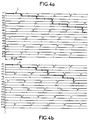
- these time values are reproduced on the timing diagrams 4a and 4b corresponding, respectively, to the standards 625 lines CCIR and 525 lines US.
- the effective integration of the loads is carried out by the commands K1, K4, K7, K10, K13 and K16 over periods equal to approximately 60 ⁇ s, represented on the timing diagrams by the high level of the control signals, separated by resets of 4 ⁇ s made on the low levels; by the other commands K2, K3, K5, K6, K8, K9, K11, K12, K14, K15, K17 and K18, are controlled, at a rate of 64 ⁇ s for the CCIR standard and 63.49 ⁇ s for the US standard , load transfers between interconnected intermediate capacities.
- the number of intermediate capacities required, and therefore of intermediate commands, as well as the values of the time offset between the different storage periods of the charges of each sensor, as illustrated in FIGS. 4a and 4b, and of the delay between the blocks A and B introduced by the delay line 61, are calculated, as a function of the characteristics of the standard, as in the case of detectors with rows of aligned sensors, as regards the calculations relating to the same block, and as in the case of '' a detector with offset rows for calculating the delay between blocks. These calculations are justified below.
- the instants of the start of integration and of transfer transmitted to the sensors, to the capacitors and to the delay lines by the commands of the detector of the multistandard camera according to the invention, for example by the commands K1 to K18 of the preceding example, are developed in the detector plane by a sequencer comprising counting means.
- these counting means consist of a first series of presettable counters as a function of the characteristics of the selected TV standard - sampling frequency, line synchronization - to provide commands for the first corresponding integration capacities.
- the outputs of the first series of counters are coupled to a second series of adjustable counters according to the period of integration of the charges in the integration capacities.
- the time periods are counted in number of clock cycles from the value of the sampling frequency.
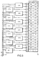
- FIG. 5 illustrates an elementary structure of programmable and adjustable counters supplying, from an 8 MHz clock, the commands K1 to K18 of the first two columns of sensors of the detector illustrated in FIG. 3.
- It has 6 first programmable counters CP1 to CP6, the outputs of which are connected respectively to the inputs of 6 other adjustable counters, CR1 to CR6.
- the count adjustment instructions from the external memory (not shown in FIG. 5) and corresponding to the characteristics of the type of standard selected, are supplied to the counters by a line LR belonging to a bus line.
- the counters CP1 to CP6 receive as input the line synchronization pulse signals and the clock signals defining the counting frequency, from lines LS and LH also belonging to the bus line.
- the meters of the second series, CR1 to CR6, are connected to the lines LR and LH, to integrate the period of integration of the charges of the chosen standard.
- the counting of the clock cycles by the counters CP1 to CP6 is controlled from the line synchronization pulses supplied by LS, function of the scanning speed, and the counting of the cycles clock by the counters CR1 to CR6 is triggered by the output pulses of the counters CP1 to CP6.
- the counters CP1 to CP6 transmit the integration commands K1, K4, K7, K10, K13 and K16.
- the counters CR1 to CR6 each have two outputs which provide, respectively, the transfer commands K3 then K2, K6 then K5, K9 then K8, K12 then K11, K15 then K14, K18 then K17.
- the commands K2, K5, K8, K11, K14 and K17 trigger the transfer of the loads from the integration capacities to the first intermediate capacities, coinciding with the instants of accumulation of charges from the second intermediate capacities to the first intermediate capacities of the upper row. This coincidence obviously does not concern the charges of the sensors in the first row of each block.
- the commands K3, K6, K9, K12, K15 and K18 trigger the transfer of the loads from the first intermediate capacities to the second intermediate capacities.
- the transfer orders have the line period for the period, i.e. 63.49 ⁇ s for the standard US and 64 ⁇ s for the CCIR standard, the integration time being preset to 60 ⁇ s and 59.51 ⁇ s according to the standard, CCIR 625 lines and US 525 lines.
- the moments of charge transfer between the first and second intermediate capacities are offset in time by the duration of discharge of the charges from the storage wells, conventionally equal to 4 ⁇ s, ie 32 clock cycles in the example of a sampling frequency of 8 MHz.
- This time difference is linked between the outputs of the counters CR1 to CR6 by the use of a delay line integrated in each adjustable counter.
- the difference of 4 cycles between the storage times in the intermediate capacities associated with the 2 reference standards described comes from the difference in line period and therefore of integration time of 0.51 ⁇ s.
- the programmable means consist of storage memories or FIFO memories, initials of First-In First-Out in Anglo-Saxon terminology.
- the FIFOs provide, by setting adapted to the standard to be transmitted, the integration commands to the integration capacities.
- the outputs are coupled to other secondary FIFO memories generating the transfer commands to the intermediate capacities.
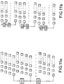
- FIG. 6 represents an example of implementation of these FIFO memories used as adjustable time counters.
- the beginnings of integration of integration capacities are determined by the first 6 FIFO memories, F1 to F6, which are loaded when the camera is started up according to the choice of standard. FIFOs are looped back to themselves in normal operation by setting an input switch to position 2.
- the 6 FIFOs deliver the pulses at the start of charge integration in the integration capacities which are controlled by K1, K4, K7, K10, K13 and K16 respectively.
- Each memory F1 to F6 also transmits its pulses in a group of 4 secondary FIFO memories, connected in parallel, F i1 to F i4 coupled to the output of the memory Fi, i varying from 1 to 6.
- These 6 groups of 4 secondary memories define 4 durations, switchable in a switch, respectively Q1 to Q6, to provide, depending on the standard chosen by the external control, the integration duration in the integration capacities.
- the durations counted by the secondary FIFO memories correspond to the transfer of charges from the first intermediate capacities to the seconds, triggered by the commands K3, K6, K9, K12, K15 and K18.
- a last FIFO memory, F'1 to F'6, of approximately 32 clock cycles, corresponding to the time for discharging the charges from the integration capacitors, makes it possible, at the output of each switch Q1 to Q6, to deliver a impetus to mark the moment of end of integration and transfer of charges to the first intermediate capacities. These transfers are regulated in conjunction with the K2, K5, K8, K11, K14 and K17 commands.
- the invention also applies when the detector consists of sensors organized according to one of the two known types of organization, successively described above. In each of these cases, the calculation of the integration periods and the moments of charge transfer is explained below on the basis of the characteristics of these organizations and different television standards.
- FIG. 7 is illustrated the so-called offset organization, the N elementary sensors of a linear bar are arranged in n rows SR1, SR2, SR3, ..., SRn, horizontally offset one with respect to to the next of D, the first sensors of these rows being referenced respectively C1, C2, C3, ..., Cn.
- n is limited to 4 in FIG. 6 but can have a higher value.
- Each row consists of N / n sensors.
- the offset D along the horizontal direction DH of the sub-rows is equal to half a sensor length along this direction, so as to comply with the Shannon sampling theorem. In fact, under these conditions, the signal sampling frequency is equal to twice the spatial cutoff frequency linked to the spacing of the elementary sensors.
- the value of the offset D and the number n of rows condition the value of the step ps between sensors of the same row according to the direction DH, ps being equal to the product of D by n.
- a last parameter d1 not between the rows in the vertical direction DV perpendicular to DH, makes it possible to characterize the organization of the sensors in offset rows.
- the sensors of the same row SRi, i varying from 1 to n, are connected to the inputs of an associated charge transfer register, CTi respectively.
- the transfer registers are connected to a multiplexer M via delay lines LR1 to LRn ⁇ 1, or LR1 to LR3 in the example illustrated, respectively coupled to the outputs of the transfer registers CT1 to CT3, the output of the register CT4 n ' not being delayed.
- the charges created at the level of each elementary sensor of each sub-row SRi are stored, during storage periods adapted to a television standard, in an integration capacity, then in an intermediate capacity, before being transmitted to the transfer register CTi associated with the corresponding row SRi.
- the capacities (not shown) are, in a known manner, used in CMOS technology while CCD technology implements storage wells; the input and output flows are controlled by suitable potential differences.
- the charges instead of being transferred to a transfer register, are read directly using a multiplexing circuit.
- the frequency of reading or transfer of charges is such that, for the maximum duration of a line of image, the charges originating from the same row are read or transferred. This basic rule of adaptation to the standard is found for all forms of sensor organization.
- the signals are delayed in the corresponding delay line LRi, by a duration established so as to synchronize the series of signals corresponding to the same image line.
- the resynchronized signals are multiplexed to provide the output, after amplification via an amplifier A, the video signal S.
- the television standard of the display monitor imposes values for the duration of storage of the charges in the storage capacities and the duration of delay of the signals in the delay lines. The relationships between these durations and the type of standard used are explained below.
- FIG. 8 illustrates another type of organization and processing of the signals from the sensors aimed at increasing the sensitivity of a detector to N sensors.
- the N sensors associated with an image line are divided into k rows of N / k sensors, SR'1, SR'2, ..., SR'k, k being equal to four in the example illustrated but may have value significantly superior.
- the rows, of which only the first sensors C1, C2, ... Ck are referenced, are aligned repeatedly and are spaced vertically by a step d2.
- the sensors therefore form N / k vertical columns of k sensors each.
- the sensors of the same column are conventionally connected to each other via integration circuits with delay known as TDI, initials of "Time Delay and Integration” in English terminology, making it possible to transfer the signals from each sensor with delay to an RS output register and accumulate them, in synchronism with the line scanning.
- TDI delay time Delay and Integration
- the charges released by each sensor of a row SR'j, j varying from 1 to k are stored via the processing circuit, in an integration capacity and then in intermediate storage capacities; the charges contained in the intermediate capacities corresponding to the row SR'j are added to the charges of the intermediate capacities corresponding to the sensors of the same column of the sub-row SR'j + 1, in synchronism with the vertical scanning.
- the storage periods in the capacities are adapted to this synchronism in order to achieve the accumulation of the charges transmitted to the output register RS, constituted by a shift reading register or a multiplexing circuit.
- This output register must provide a video signal at a frequency compatible with the television standard used.
- the storage periods in the integration capacities and in the intermediate capacities, as well as the number of intermediate capacities are calculated by adopting the following rule, already mentioned: the charges contained in a capacity must be transferred before it can be used to store other charges, so the transfer takes place at the rate of the line frequency.
- the integration periods begin and end at different times for the different sensors, which requires as many clock commands as there are sensors.
- the charges of the sensors C1, C2, ... are integrated and released from the integration capacities successively with a time offset by sensor equal to d / v ; and for each sensor C1, C2, ..., or Cn, the integration periods corresponding to the successive image lines L1, L2, ..., Lp, follow one another in time following instants separated by a time offset per line, hereinafter called line period, equal to f / v.
- FIGS. 9a to 9d translate, respectively for the different standards, the spread over time of the integration periods defined by table I for the first sensors C1 to C4 of any of the two types of organization described. For each sensor, the integration periods follow one another in time at instants separated by f / v corresponding to successive image lines L1, L2, L3, L4, L5, L6, etc.
- Table V gives the numerical values of these characteristics for the different standards, illustrated on the timing diagrams 9a to 9d: TABLE V Chronogram 9a 9b 9c 9d Standard CCIR US 875 525 Spacing distance f ( ⁇ m) 16.5 19.5 11.7 19.5 Analysis speed v (m / Ls) 0.26 0.31 0.31 1.31 Distance between sub-rows ( ⁇ m) 30 30 30 16 f / v ( ⁇ m) 64 63.49 38.1 63.49 Time offset d / v ( ⁇ s) 116.5 97.5 97.6 52
- the loads are transferred to the intermediate capacities.
- the storage times in the intermediate capacities obey the rule of maximum occupation of these capacities during the duration of an image line.
- the number of intermediate stages g that is to say the number of intermediate storage capacities, is equal to the whole immediately greater than the ratio between the time offset of the instants of transfer of the integrated charges from one sensor to the next to form the same line and the time shift from one image line to the next.
- the signals are then delayed, as described above, in the different delay lines LR1 to LR3 before being multiplexed in the multiplexer M.
- the number of intermediate stages to be envisaged occurs at the level of each delay line in this example of offset implementation. This number is equal to the integer closest to the ratio between the delay time of the delay line, equal to the time offset from one sensor to another, and the duration of transfer in the multiplexing circuit or transfer.
- the delay times are, for lines LR1 to LR3, respectively 349.5 ⁇ s, 233 ⁇ s and 116.5 ⁇ s and the number of stages of 960; 640 and 320 for a transfer time of 0.36 ⁇ s.
- Such a structure comprises a single transfer circuit CT connected to all the sensors, such as C1, C2, C3, C4, via delay circuits, such as R1, R2, R3, for sensors C1 to C3, respectively introducing the same delays as the previous delay lines, namely in the example of the 625 CCIR standard: 349.5 ⁇ s, 233 ⁇ s and 116.5 ⁇ s.
- the number of stages to be provided in these delay circuits defined by the integer closest to the ratio between the delay time and the line period, is the same for all circuits with delay connected to the same row of sensors. For example, for the 625 CCIR standard, it is respectively 6; 4 and 2 stages for rows SR1 to SR3, with a line duration of 64 ⁇ s.
- This last example of a reading circuit structure for realizing the delay of the charges of a detector with offset rows, differs only from the TDI type management structure by the variable number of intermediate capacities along the row.
- the invention applies not only to sensors with offset or repeated rows, that is to say without offset, in particular to a number of rows greater than 4, but also to sensors more generally having a combination of the two types previous organization, allowing to combine the advantages of each.
- the aligned rows are coupled through integration and intermediate storage capacities forming circuits called TDI circuits due to their TDI mode of management over time, as previously described. Only the TDI circuits associated with the first aligned sensors are shown in Figures 11a and 11b to maintain their readability. These rows can be compared to a single master row giving a signal level k times higher and a noise level multiplied by a factor k , provided that the transfer of charges from these rows respects the periods of integration and storage in the intermediate capacities corresponding to the desired standard, as described above.
- n offset master rows are done according to one of the two embodiments previously described for the treatment of the charges coming from offset sensor rows, that is to say either by transmission with n charge transfer circuits. coupled to n-1 delay lines, either by transmission to a single charge transfer circuit via as many delay circuits as there are sensors, with the exception of course of those of the first mother row.
Abstract
Description
Le domaine de l'invention est celui de la prise de vues, notamment dans le domaine infrarouge et se rapporte, plus précisément, aux caméras d'observation destinées à délivrer un signal vidéo à un moniteur de visualisation pour la formation d'images selon le standard adapté à ce moniteur.The field of the invention is that of taking pictures, in particular in the infrared field and relates, more precisely, to observation cameras intended to deliver a video signal to a display monitor for the formation of images according to the standard suitable for this monitor.
L'invention a pour objet une caméra d'observation multistandard dont le signal vidéo de sortie peut être adapté à plusieurs standards de télévision.The subject of the invention is a multistandard observation camera, the video output signal of which can be adapted to several television standards.
L'invention concerne plus particulièrement, mais non exclusivement, les caméras thermiques et peut être utilisée dans les systèmes de surveillance panoramique ou sectorielle.The invention relates more particularly, but not exclusively, to thermal cameras and can be used in panoramic or sectoral surveillance systems.
Pour convertir le flux lumineux provenant d'une scène à observer en un signal vidéo, les caméras thermiques comportent classiquement un détecteur, disposé dans un cryostat, et comportant notamment un grand nombre de capteurs élémentaires ; ces capteurs sont sensibles dans une bande spectrale infrarouge donnée et sont capables de délivrer des charges dont la quantité est proportionnelle à l'éclairement reçu. Les charges délivrées sont transmises à un circuit de traitement et de multiplexage ; les transferts des charges dans un tel circuit sont déclenchés par les impulsions d'un séquenceur d'horloges réglées de façon à former un signal vidéo conforme au standard du moniteur de visualisation.To convert the light flux coming from a scene to be observed into a video signal, thermal cameras conventionally comprise a detector, placed in a cryostat, and notably comprising a large number of elementary sensors; these sensors are sensitive in a given infrared spectral band and are capable of delivering charges the quantity of which is proportional to the illumination received. The charges delivered are transmitted to a processing and multiplexing circuit; the charge transfers in such a circuit are triggered by the pulses of a clock sequencer adjusted so as to form a video signal conforming to the standard of the display monitor.
Les capteurs élémentaires sont disposés selon la direction horizontale de l'image finale, qui est formée à partir du signal vidéo délivré par la caméra et visualisée sur le moniteur.The elementary sensors are arranged in the horizontal direction of the final image, which is formed from the video signal delivered by the camera and displayed on the monitor.
De manière générale, les capteurs élémentaires sont organisées en plusieurs rangées parallèles à cette même direction horizontale, et le détecteur est associé à un système opto-mécanique de projection et de balayage vertical d'une image de la scène projetée sur le détecteur. Le détecteur analyse alors la scène par ligne de trame ou d'image visualisée sur le moniteur, la géométrie de ces lignes étant fixée par le standard de visualisation.In general, the elementary sensors are organized in several rows parallel to this same horizontal direction, and the detector is associated with an opto-mechanical system for projecting and vertically scanning an image of the scene projected on the detector. The detector then analyzes the scene by frame or image line viewed on the monitor, the geometry of these lines being fixed by the viewing standard.
L'organisation des capteurs élémentaires en plusieurs rangées obéit en fait à plusieurs objectifs :
- présenter un nombre suffisant de capteurs dans une longueur de détecteur donnée, par exemple de 6,33 mm ;
- respecter le théorème d'échantillonnage de Shannon concernant la fréquence d'échantillonnage du signal, ce qui nécessite le recouvrement des zones de détection ;
- augmenter la sensibilité du détecteur par accumulation avec retard, selon une méthode connue, des signaux provenant de différentes zones de détection et correspondant à un même point d'image de la scène successivement observée.
- present a sufficient number of sensors in a given detector length, for example 6.33 mm;
- respect Shannon's sampling theorem concerning the signal sampling frequency, which requires overlapping the detection zones;
- increase the sensitivity of the detector by accumulation with delay, according to a known method, of signals coming from different detection zones and corresponding to the same image point of the scene successively observed.
Classiquement, deux types d'organisation de rangées existent indépendamment :
- afin de tenir compte du théorème d'échantillonnage, les rangées se présentent décalées selon la direction horizontale, d'une distance égale à la moitié de la dimension d'un capteur selon cette direction et les signaux de sortie sont alors resynchronisés dans le circuit de traitement en synchronisme avec le balayage vertical avec recouvrement partiel des informations de luminance ;
- afin d'augmenter la sensibilité, chaque rangée est répétée plusieurs fois, sans décalage horizontal ; les signaux des capteurs homologues, situés sur une même verticale correspondant à un même point d'image du fait du balayage vertical, sont cumulés en synchronisme avec le balayage dans le circuit de traitement selon le mode connu dit d'Intégration avec Retard, en abrégé TDI (initiales de "Time Delay and Integration" en terminologie anglo-saxonne).
- in order to take account of the sampling theorem, the rows are offset in the horizontal direction, by a distance equal to half the dimension of a sensor in this direction and the output signals are then resynchronized in the circuit processing in synchronism with scanning vertical with partial overlap of the luminance information;
- in order to increase the sensitivity, each row is repeated several times, without horizontal shift; the signals from the homologous sensors, located on the same vertical corresponding to the same image point due to the vertical scanning, are accumulated in synchronism with the scanning in the processing circuit according to the known mode known as Integration with Delay, for short TDI (initials of "Time Delay and Integration" in Anglo-Saxon terminology).
Le problème posé est de disposer d'un équipement de prise de vues qui puisse à la fois répondre aux conditions d'échantillonnage et de sensibilité évoquées afin d'obtenir une image de qualité et être adapté à plusieurs standards de télévision.The problem posed is to have shooting equipment which can both respond to the sampling and sensitivity conditions mentioned in order to obtain a quality image and be adapted to several television standards.
Or, les deux premières conditions (échantillonnage et sensibilité) entrainent l'utilisation d'un nombre de rangées assez grand, et la troisième condition (adaptation à plusieurs standards de télévision) suppose que les instants de transfert de charges soient élaborés indépendamment pour chaque rangée et soient différents pour chaque standard, ce qui nécessite d'engendrer un nombre correspondant de signaux d'horloge. Ces signaux étant élaborés dans une "électronique de proximité" disposée à l'extérieur du cryostat, le nombre de connexions vers l'extérieur du cryostat, proportionnel au nombre de rangées, devient très élevé ; de sérieures difficultés de connectique et de fuites thermiques se posent alors.However, the first two conditions (sampling and sensitivity) entail the use of a fairly large number of rows, and the third condition (adaptation to several television standards) assumes that the moments of charge transfer are developed independently for each row and are different for each standard, which requires generating a corresponding number of clock signals. These signals being developed in "proximity electronics" located outside the cryostat, the number of connections to the outside of the cryostat, proportional to the number of rows, becomes very high; serious connection problems and thermal leaks then arise.
De ce fait, la disposition des capteurs en sous-rangées décalées ou répétées n'est rendu compatible jusqu à présent qu'avec un seul standard et que pour un seul type d'organisation de rangées à l'exclusion de l'autre : la compatibilité au standard est obtenue classiquement en réglant le pas entre rangées sur un sous-multiple entier de l'écartement entre les lignes d'image ou de trames du standard de télévision considéré ; la mise en oeuvre d'un seul type d'organisation de capteurs avec un nombre restreint de rangées permet alors de limiter les problèmes de connexion.As a result, the arrangement of sensors in offset or repeated sub-rows is only made compatible so far with one standard and only for one type of row organization to the exclusion of the other: the compatibility with the standard is obtained conventionally by adjusting the pitch between rows over an integer sub-multiple of the spacing between the picture or field lines of the television standard in question; the implementation of a single type of organization of sensors with a limited number of rows then makes it possible to limit the connection problems.
On connaît par exemple une barrette de 288 x 4 capteurs développée par la Société SOFRADIR. Cette barrette a été utilisée en association avec un dispositif de balayage horizontal, direction dans laquelle les standards de télévision ne sont pas quantifiés.We know, for example, a 288 x 4 sensor strip developed by the SOFRADIR Company. This bar was used in combination with a horizontal scanning device, a direction in which television standards are not quantified.
Afin de disposer d'une caméra apte à fournir une image de qualité et adaptable aux principaux standards de télévision, sans que se posent les délicats problèmes de connexion évoqués, il est proposé de réaliser la gestion temporelle des différentes impulsions de commande de l'intégration et des transferts des charges provenant des capteurs par des moyens de comptage situés dans le cryostat, programmables de l'extérieur en fonction des caractéristiques d'un standard choisi, et combinés entre eux en fonction de l'organisation des sous-rangées de capteurs de façon à simplifier la commande de tous ces déplacements de charges.In order to have a camera capable of providing a quality image and adaptable to the main television standards, without posing the delicate connection problems mentioned, it is proposed to carry out the time management of the different integration control pulses. and charge transfers from the sensors by counting means located in the cryostat, programmable from the outside according to the characteristics of a chosen standard, and combined with each other according to the organization of the sub-rows of so as to simplify the control of all these load displacements.
Plus précisément, l'objet de l'invention concerne une caméra d'observation multistandard comportant
- un détecteur de longueur donnée, photosensible dans une bande spectrale donnée et comprenant des capteurs élémentaires disposés en rangées sur la longueur du détecteur selon une même direction horizontale pour former une structure de type donné,
- un système opto-mécanique de projection et de balayage, pour projeter une image d'une scène observée de largeur sensiblement égale à la longueur du détecteur, dans un plan focal coïncidant avec le plan du détecteur et pour balayer cette image sur le détecteur selon une direction verticale,
- un cryostat dans lequel sont disposés le détecteur et, associé à celui-ci, un circuit de lecture pour délivrer, à partir des charges libérées proportionnellement à l'éclairement reçu par les capteurs, puis transférées et multiplexées par la commande d'un séquenceur d'horloges en synchronisme avec le balayage vertical, un signal vidéo à un moniteur de visualisation ayant un standard de télévision donné, ce standard étant défini par une fréquence de ligne et, pour la TV numérique, par une fréquence d'échantillonnage caractéristique des images visualisées,
la caméra étant caractérisée en ce que le séquenceur d'horloges est disposé dans le cryostat et comporte des moyens de comptage du temps pour définir des périodes d'intégration des charges et des instants de transfert et de multiplexage de ces charges après intégration dans le circuit de lecture, et en ce que ces moyens de comptage sont préréglés par une mémoire disposée à l'extérieur du cryostat et qui contient des instructions de synchronisation des périodes d'intégration, des instants de transfert et de multiplexage avec la fréquence ligne d'un standard de télévision choisi parmi plusieurs standards présélectionnés dans la mémoire et correspondant au standard du moniteur de visualisation.More specifically, the subject of the invention relates to a multistandard observation camera comprising
- a detector of given length, photosensitive in a given spectral band and comprising elementary sensors arranged in rows along the length of the detector in the same horizontal direction to form a structure of given type,
- an opto-mechanical projection and scanning system, for projecting an image of an observed scene of width substantially equal to the length of the detector, in a focal plane coinciding with the plane of the detector and to scan this image on the detector in a vertical direction,
- a cryostat in which the detector is arranged and, associated with this, a reading circuit for delivering, from the charges released in proportion to the illumination received by the sensors, then transferred and multiplexed by the control of a sequencer d clocks in synchronism with vertical scanning, a video signal to a display monitor having a given television standard, this standard being defined by a line frequency and, for digital TV, by a sampling frequency characteristic of the images viewed ,
the camera being characterized in that the clock sequencer is arranged in the cryostat and includes time counting means for defining periods of integration of the charges and instants of transfer and multiplexing of these charges after integration into the circuit of reading, and in that these counting means are preset by a memory arranged outside the cryostat and which contains instructions for synchronizing the integration periods, instants of transfer and multiplexing with the line frequency of a television standard chosen from several standards preselected in the memory and corresponding to the standard of the display monitor.
La caméra selon l'invention peut s'adapter à plusieurs standards de télévision en utilisant un même détecteur. De plus, le pas entre les sous-rangées de capteurs de ce détecteur n'est plus lié par le pas entre les lignes de télévision. Il est alors possible d'adapter le pas entre les rangées aux seules contraintes technologiques, de manière à simplifier la connectique entre le détecteur et l'électronique de proximité.The camera according to the invention can be adapted to several television standards by using the same detector. In addition, the pitch between the sub-rows of sensors of this detector is no longer linked by the pitch between the television lines. It is then possible to adapt the pitch between the rows solely to technological constraints, so as to simplify the connection between the detector and the proximity electronics.
Dans une forme de réalisation, les moyens de comptage programmables comprennent des compteurs de cycles d'horloge pour définir les périodes d'intégration, couplés à d'autres compteurs pour définir les instants de transfert, les cycles étant définis par la fréquence d'échantillonnage et les compteurs étant déclenchés en synchronisme avec la fréquence ligne du moniteur.In one embodiment, the programmable counting means comprise clock cycle counters to define the integration periods, coupled to other counters to define the transfer times, the cycles being defined by the sampling frequency and the counters being triggered in synchronism with the line frequency of the monitor.
Dans une autre forme de réalisation, les moyens de comptage sont constitués par des mémoires à accumulation appelées également mémoires FIFO (initiales de "First In, First Out" en terminologie anglo-saxonne).In another embodiment, the counting means consist of storage memories also called FIFO memories (initials of "First In, First Out" in English terminology).
Selon l'invention, les moyens de comptage peuvent recevoir les instructions de programmation à tout instant en fonction du standard choisi par l'opérateur, par exemple à chaque mise en route de la caméra.According to the invention, the counting means can receive the programming instructions at any time according to the standard chosen by the operator, for example each time the camera is started.
La caméra selon l'invention peut être avantageusement utilisée dans un système de surveillance sectoriel ou panoramique.The camera according to the invention can advantageously be used in a sectoral or panoramic surveillance system.
D'autres avantages et caractéristiques apparaîtront à la lecture de la description qui suit, exposée en référence aux figures annexées qui représentent respectivement :
- la figure 1, la structure schématisée d'une caméra d'observation de type caméra thermique ;
- la figure 2, un schéma synoptique représentant l'agencement selon l'invention de certains éléments matériels d'une telle structure ;
- la figure 3, un exemple de réalisation d'un agencement de capteurs combinant deux types d'organisation ;
- les figures 4a et 4b, deux chronogrammes de périodes et d'instants d'intégration et de transfert des charges de l'exemple de réalisation précédent adapté à deux standards de télévision ;
- la figure 5, une forme de réalisation d'un séquenceur à compteurs programmables ;
- la figure 6, une forme de réalisation d'un séquenceur à mémoires FIFO ;
- les figures 7 et 8, deux types d'organisation connus pour les capteurs élémentaires de détecteurs utilisés et les circuits de traitement associés ;
- les figures 9a à 9d, des chronogrammes de périodes d'intégration des charges des premiers capteurs pour quatre standards de télévision connus ;
- la figure 10, une variante de circuit de traitement pour les charges provenant des capteurs organisés en sous-rangées décalées,
- les figures 11a et 11b, deux types d'organisation combinée de rangées de capteurs.
- FIG. 1, the schematic structure of an observation camera of the thermal camera type;
- Figure 2, a block diagram showing the arrangement according to the invention of certain material elements of such a structure;
- FIG. 3, an exemplary embodiment of an arrangement of sensors combining two types of organization;
- Figures 4a and 4b, two timing diagrams of periods and instants of integration and transfer loads of the previous embodiment adapted to two television standards;
- FIG. 5, an embodiment of a sequencer with programmable counters;
- FIG. 6, an embodiment of a FIFO memory sequencer;
- FIGS. 7 and 8, two types of organization known for the elementary sensors of detectors used and the associated processing circuits;
- FIGS. 9a to 9d, chronograms of periods of integration of the charges of the first sensors for four known television standards;
- FIG. 10, a variant of the processing circuit for the charges coming from the sensors organized in offset sub-rows,
- FIGS. 11a and 11b, two types of combined organization of rows of sensors.
Les caméras thermiques fonctionnent classiquement dans une des bandes spectrales 8 à 12 µm ou 3 à 5 µm, qui est la bande de sensibilité de leur détecteur ; le détecteur a une structure de barrette détectrice à balayage vertical. Un exemple de structure d'une telle caméra est représenté schématiquement sur la figure 1. Sur cette figure, la caméra comporte essentiellement, dans le sens de la propagation de la lumière, un système optique afocal d'entrée 1, dont le grossissement est adapté au champ d'observation désiré, un miroir de balayage vertical 2, un système optique de focalisation 3 et une barrette photosensible 4 enfermée dans une enceinte cryostatique 5 refroidie. Ce cryostat est clos par un hublot 6 transparent aux rayonnements infrarouges dans la bande considérée ; le champ de vue du détecteur est limité par un diaphragme froid 6', encore appelé écran froid, placé à l'intérieur du cryostat.Thermal imaging cameras conventionally operate in one of the 8 to 12 µm or 3 to 5 µm spectral bands, which is the sensitivity band of their detector; the detector has a vertical scanning detector strip structure. An example of the structure of such a camera is shown diagrammatically in FIG. 1. In this figure, the camera essentially comprises, in the direction of the propagation of the light, an afocal
Un faisceau lumineux provenant de la scène observée est collimaté à l'infini en traversant le système afocal d'entrée 1, puis est réfléchi sur le miroir 2, avant d'être projeté par le système de focalisation 3, sur la barrette 4 afin de former dans le plan de la barrette une image I de la scène observée. L'écran froid 6' peut coïncider avec la pupille de sortie du système de focalisation 3 afin de supprimer les flux parasites de structure.A light beam coming from the observed scene is collimated at infinity by crossing the
Le détecteur à balayage vertical est appelé barrette détectrice du fait de sa forme allongée dans le sens horizontal. Il comporte en effet classiquement un grand nombre de capteurs élémentaires, photovoltaïques ou photoconducteurs, disposés selon une ou plusieurs rangées dont la longueur globale conditionne celle de la barrette. Par exemple, des capteurs sensibles dans la bande spectrale 8-12 µm peuvent être des photodiodes en HgCdTe (mercure-cadmium-tellure) de 25 x 25 µm déposées par hybridation sur un substrat de silicium.The vertical scanning detector is called a detector strip because of its elongated shape in the horizontal direction. It conventionally comprises in fact a large number of elementary, photovoltaic or photoconductive sensors, arranged in one or more rows, the overall length of which conditions that of the strip. For example, sensitive sensors in the 8-12 μm spectral band can be HgCdTe (mercury-cadmium-tellurium) photodiodes of 25 × 25 μm deposited by hybridization on a silicon substrate.
Lorsque le miroir de balayage vertical associé, tel que le miroir 2, oscille autour d'un axe horizontal AA', l'image de hauteur h formée par le système de focalisation 3 est analysée ligne par ligne sur la barrette 4 par déplacement vertical selon une direction DV ; la largeur de cette image formée selon une direction DH perpendiculaire au plan de la figure 1 est la longueur L du détecteur 4.When the associated vertical scanning mirror, such as the
Afin de fournir un signal vidéo reproduisant la scène observée ligne par ligne, les charges délivrées par les capteurs élémentaires, proportionnellement à l'éclairement reçu par chacun d'eux pendant une même durée, sont traitées dans un circuit de lecture qui effectue leur intégration, leur transfert et leur multiplexage grâce à des registres de lecture à décalage ; un tel circuit, de type à transfert de charge CCD (initiales de "Charge Coupled Device" en terminologie anglosaxonne) ou CMOS, est couplé à un registre de sortie pour délivrer, après amplification, le signal vidéo.In order to provide a video signal reproducing the scene observed line by line, the charges delivered by the elementary sensors, in proportion to the illumination received by each of them for the same duration, are processed in a reading circuit which performs their integration, their transfer and their multiplexing thanks to read registers shift; such a circuit, of CCD charge transfer type (initials of "Charge Coupled Device" in English terminology) or CMOS, is coupled to an output register to deliver, after amplification, the video signal.
Pour respecter les conditions d'échantillonnage et de sensibilité exposées plus haut, les capteurs des barrettes de détection sont agencés selon plusieurs rangées définissant la structure du détecteur utilisé. De telles structures nécessitent l'élaboration de différentes commandes d'horloge pour l'intégration le transfert et le multiplexage des charges, pour chaque rangée.To comply with the sampling and sensitivity conditions described above, the sensors of the detection bars are arranged in several rows defining the structure of the detector used. Such structures require the development of different clock commands for integrating the transfer and the multiplexing of the charges, for each row.
La figure 2 représente un agencement entre les différents éléments matériels d'une caméra selon l'invention permettant de générer de telles commandes. Les différents signaux de commande d'horloge sont élaborés dans le plan du détecteur 20, confondu avec le plan focal du système optique de focalisation 3, par un séquenceur 22 comportant des moyens de comptage du temps pouvant être intégrés dans le circuit de lecture du détecteur 24 et pouvant être préréglés de l'extérieur du cryostat, à partir de signaux de synchronisation ligne et de fréquence d'échantillonnage d'un standard de télévision choisi provenant d'une mémoire externe 25. L'élaboration des signaux de commande d'horloges à l'intérieur du cryostat diminue également les bruits électriques des signaux, ce qui augmente la fiabilité de la commande.FIG. 2 represents an arrangement between the various hardware elements of a camera according to the invention making it possible to generate such commands. The different clock control signals are developed in the plane of the
Une électronique de proximité 26 comporte la mémoire 25 et une commande de sélection 27 de cette mémoire 25. La commande 27, actionnée à distance par un commutateur (non représenté), permet d'adapter les périodes d'intégration, les instants de transfert et de multiplexage des charges du circuit de lecture d'un détecteur de structure donnée au standard de visualisation désiré. L'invention assure cette compatibilité quel que soit le type d'organisation des rangées de capteurs élémentaires obtenu à partir des deux principaux types d'organisation illustrés ci-après et obéissant soit à la condition d'échantillonnage classique grâce à un décalage entre les rangées (organisation dite décalée), soit au mode de fonctionnement TDI par répétition sans décalage des rangées (organisation dite répétée).
Dans ces organisations, le nombre de rangées de capteurs peut être avantageusement grand pour les raisons exposées plus haut, et chaque rangée ayant sa propre période d'intégration, ses propres instants de transfert de charges entre les différentes capacités des registres de lecture, le nombre de signaux d'horloge à engendrer pour régler ces temps est très élevé. Ce nombre est de plus multiplié par le nombre de standards possible lorsque le détecteur est destiné à une l'utilisation multistandard visée par l'invention. L'invention permet de gérer de l'intérieur du cryostat un tel nombre de signaux d'horloge alors qu'une telle gestion était impossible lorsqu'il fallait générer tous ces signaux à partir de l'extérieur.In these organizations, the number of rows of sensors can advantageously be large for the reasons explained above, and each row having its own integration period, its own moments of charge transfer between the different capacities of the read registers, the number of clock signals to generate to set these times is very high. This number is further multiplied by the number of possible standards when the detector is intended for multistandard use targeted by the invention. The invention makes it possible to manage from the interior of the cryostat such a number of clock signals when such management was impossible when all of these signals had to be generated from the outside.
Les instructions de préréglage, relatives à la synchronisation ligne et à la fréquence d'échantillonnage d'un standard sélectionné par la commande 27, par exemple parmi les quatre standards étudiés plus loin, sont transmises par une liaison adaptée 28 de la mémoire 25, par exemple lors de la mise en route de la caméra, aux moyens de comptage programmées conformément à ces instructions. Les périodes d'intégration et de stockage intermédiaire des charges sont réglées en nombre de cycles par la fréquence d'échantillonnage et les instants d'intégration de transfert par la synchronisation ligne. Des premiers moyens de comptage 231 fournissent les impulsions de commande d'intégration et à des seconds moyens de comptage 232 réglés en fonction de la période d'intégration des charges, fournissant en fin de période d'intégration des charges les impulsions de commande de transfert.The preset instructions, relating to line synchronization and to the sampling frequency of a standard selected by the
Un exemple de réalisation de la caméra selon l'invention comporte un détecteur dont la structure est décrite ci-après : elle se compose d' une partie photosensible de rangées capteurs disposés en deux ensembles (ou blocs) décalés, comportant chacun 3 rangées alignées de 256 capteurs, combinant ainsi les deux types d'organisations principales, et d'une partie de traitement comprenant notamment des capacités d'intégration et de stockage intermédiaire des charges couplées aux moyens de comptage du temps. Ces moyens de comptage sont adaptés, d'une part, au nombre de capacités d'intégration et de stockage intermédiaire et, d'autre part, au type de standard, sélectionné par réglage des périodes d'intégration et de transfert en fonction des instructions de programmation comme décrit plus précisément ci-après.An exemplary embodiment of the camera according to the invention comprises a detector whose structure is described below: it consists of a photosensitive part of sensor rows arranged in two sets (or blocks) offset, each comprising 3 rows aligned with 256 sensors, thus combining the two main types of organization, and a processing section including in particular capacities for integration and intermediate storage of charges coupled to the time counting means. These counting means are adapted, on the one hand, to the number of integration and intermediate storage capacities and, on the other hand, to the type of standard, selected by adjusting the integration and transfer periods according to the instructions. as described more precisely below.
En technologie hybride, les capteurs photosensibles, réalisés dans un matériau tel que Cd-Hg-Te, sont hybridés sur un substrat de silicium comportant les puits ou capacités d'intégration des charges, les puits ou capacités de stockage intermédiaires et les circuits de multiplexage, à travers des liaisons de transfert de charges effectuées par exemple par des fils de microsoudure ou des billes d'indium. En technologie monolithique, les capteurs, les puits ou capacités d'intégration et de stockage et les circuits de multiplexage sont intégrés dans le même substrat ; les puits de stockage des capacités forment les étages des registres de lecture, la lecture étant effectuée par transfert des charges d'un puits à l'autre.In hybrid technology, the photosensitive sensors, made of a material such as Cd-Hg-Te, are hybridized on a silicon substrate comprising the wells or charge integration capacities, the wells or intermediate storage capacities and the multiplexing circuits. , through charge transfer links made, for example, by microweld wires or indium beads. In monolithic technology, sensors, sinks or integration and storage capacities and multiplexing circuits are integrated in the same substrate; the capacity storage wells form the floors of the read registers, the reading being carried out by transfer of the charges from one well to another.
La figure 3 représente schématiquement l'agencement des capteurs et des capacités d'intégration et de stockage associées à ces capteurs selon l'exemple de réalisation. Cet agencement n'est que partiellement représenté pour alléger la figure, en particulier seules les capacités de stockage des premiers capteurs des rangées apparaissent.FIG. 3 schematically represents the arrangement of the sensors and the integration and storage capacities associated with these sensors according to the embodiment example. This arrangement is only partially shown to lighten the figure, in particular only the storage capacities of the first sensors of the rows appear.
Les capteurs forment deux blocs, A et B, décalés d'un pas égal à la dimension d'un capteur selon la direction horizontale définie par les rangées ; chaque bloc comprend 3 rangées alignées ayant chacune 256 capteurs. Les capteurs, de dimension 25 µm x 25 µm, forment 512 colonnes verticales de 3 capteurs décalées de 25 µm, ce qui impose 12,8 mm comme longueur de détecteur et donc comme largeur de l'image projetée sur ce détecteur.The sensors form two blocks, A and B, offset by a step equal to the dimension of a sensor in the horizontal direction defined by the rows; each block includes 3 aligned rows each having 256 sensors. The sensors, 25 µm x 25 µm in size, form 512 vertical columns of 3 sensors offset by 25 µm, which requires 12.8 mm as detector length and therefore as the width of the image projected on this detector.
Le pas d2 entre rangées non décalées d'un même bloc est de 62, 5 µm et le pas d1 de décalage du bloc à bloc est de 175 µm.The step d2 between rows not offset by the same block is 62.5 μm and the step d1 for shifting the block to block is 175 μm.
Dans un même bloc, le stockage et les transferts des charges se font en mode TDI avec, comme décrit précédemment, accumulation des charges des capteurs d'une même colonne en synchronisme avec le balayage ligne à ligne de l'image sur le détecteur. Cette accumulation est effectuée dans les capacités intermédiaires. Sur la figure 3, chaque premier capteur des rangées, Ca, Cb ou Cc pour le bloc A et Cd, Ce ou Cf pour le bloc B est relié à une capacité d'intégration de charges, respectivement Cia, Cib, Cic, Cid, Cie ou Cif. Chaque capacité d'intégration Cia à Cif est couplée à deux capacités intermédiaires successives, respectivement C'ia et C''ia reliées à Cia, C'ib et C''ib à Cib, C'ic à C'if à Cif. Le rôle et le nombre de ces capacités intermédiaires sont décrits plus loin.In the same block, the storage and the transfer of the charges are done in TDI mode with, as described above, accumulation of the charges of the sensors of the same column in synchronism with the line-by-line scanning of the image on the detector. This accumulation is carried out in the intermediate capacities. In FIG. 3, each first row sensor, Ca, Cb or Cc for block A and Cd, Ce or Cf for block B is connected to a charge integration capacity, respectively Cia, Cib, Cic, Cid, Cie or Cif. Each integration capacity Cia to Cif is coupled to two successive intermediate capacities, respectively C'ia and C''ia connected to C ia , C ' ib and C'' ib to C ib , C ' ic to C' if to C if . The role and number of these intermediate capacities are described below.
Les charges fournies par les capteurs sont stockées dans les capacités d'intégration puis transférées successivement dans les capacités intermédiaires. A la sortie de la dernière capacité intermédiaire, les charges d'un capteur sont cumulées à celles stockées dans les capacités intermédiaires du capteur de la même colonne situé immédiatement au-dessus, les capteurs ayant reçu le même flux de lumière selon le principe du TDI. Ainsi, sur la figure 3, la capacité C''ia est reliée à la capacité C'ib, la capacité C''ib à la capacité C'ic, la capacité C''id à la capacité C'ie et la capacité C''ie à la capacité C'if.The charges supplied by the sensors are stored in the integration capacities and then transferred successively to the intermediate capacities. At the output of the last intermediate capacity, the charges of a sensor are added to those stored in the intermediate capacities of the sensor in the same column located immediately above, the sensors having received the same light flux according to the principle of TDI . Thus, in Figure 3, the capacity C '' ia is related to the capacity C ' ib , the capacity C'' ib to the capacity C' ic , the capacity C '' id to the capacity C ' ie and the capacity C '' ie to the capacity C ' if .
Les rangées d'un même bloc fonctionnant en mode TDI sont équivalentes à une seule rangée-mère comme décrit plus loin. Les deux rangées-mères décalées ainsi formées fonctionnent selon un mode "décalage" qui consiste, comme décrit plus loin, à synchroniser les signaux issus des capteurs par des lignes à retard pour obtenir une séquence vidéo. De même, les signaux provenant d'une même colonne de capteurs dans l'exemple de réalisation présent, illustré à la figure 3, sont synchronisés après transmission à un registre de transfert de charges par bloc, TCA pour le bloc A et TCB pour le bloc B par une ligne à retard. Pour cela, les sorties des registres TCA et TCB sont reliées à un multiplexeur 60, à travers une ligne à retard 61 pour la sortie de TCA. Le multiplexeur et les sorties des registres TCA et TCB sont commandés par un inverseur 62 dont la cadence est réglée à partir de la fréquence d'échantillonnage. L'inverseur 62 permet la synchronisation, en alternance, des sorties des circuits TCA et TCB à une fréquence égale à la fréquence d'échantillonnage. Le multiplexeur 60 fournit le signal vidéo de sortie S après amplification et filtrage à travers un circuit de post-traitement 63.The rows of the same block operating in TDI mode are equivalent to a single parent row as described below. The two offset master rows thus formed operate according to an "offset" mode which consists, as described below, in synchronizing the signals from the sensors by delay lines to obtain a video sequence. Similarly, the signals coming from the same column of sensors in the present embodiment, illustrated in FIG. 3, are synchronized after transmission to a charge transfer register per block, TCA for block A and TCB for the block B by a delay line. For this, the outputs of the registers TCA and TCB are connected to a
Pour la gestion temporelle de ce détecteur, il est tout d'abord nécessaire de définir la succession dans le temps des périodes d'intégration et de transfert de charges dans les capacités, qui doit être commandée par les moyens de comptage, cette succession étant adaptée aux caractéristiques du standard sélectionné.For the temporal management of this detector, it is first of all necessary to define the succession over time of the periods of integration and transfer of charges in the capacities, which must be controlled by the counting means, this succession being adapted to the characteristics of the selected standard.
Ces commandes sont référencées de K1 à K18 dans l'exemple de la figure 3 limité aux premiers capteurs. Afin de faciliter le décompte des périodes de temps, il convient de distinguer deux types de commande : celles qui règlent les temps d'intégration des charges des capteurs Ca à Cf dans les capacités d' intégration Cia à Cif, respectivement les commandes K1, K4, K7, K10, K13 et K16 ; et celles qui règlent les instants de transfert entre les capacités intermédiaires Cia et C'ia, C'ia et C''ia, Cib et C'ib, C'ib et C''ib, Cic et C'ic, C'ic et C''ic, Cid et C'id, C'id et C''id, Cie et C'ie, C'ie et C''ie, Cif et C'if, établis respectivement par les commandes K2, K3, K5, K6, K8, K9, K11, K12, K14, K15 et K17. Certaines commandes doivent gérer des transferts simultanés pour cumuler les charges selon le principe du TDI : il s'agit des commandes K5, K8, K14 et K17 qui règlent également et respectivement, outre les temps transferts déjà indiqués, ceux entre C''ia et C'ib, C''ib et C'ic, C''id et C'ie, C'ie et C'if.These commands are referenced from K1 to K18 in the example of FIG. 3 limited to the first sensors. In order to facilitate the counting of the periods of time, it is advisable to distinguish two types of control: those which regulate the times of integration of the charges of the sensors C a to C f in the capacities of integration C ia to C if , respectively the commands K1, K4, K7, K10, K13 and K16; and those which regulate the moments of transfer between the intermediate capacities C ia and C ' ia , C' ia and C '' ia , C ib and C ' ib , C' ib and C '' ib , C ic and C ' ic , C ' ic and C'' ic , C id and C' id , C ' id and C'' id , C ie and C' ie , C ' ie and C'' ie , C if and C' if , established respectively by the commands K2, K3, K5, K6, K8, K9, K11, K12, K14, K15 and K17. Certain commands must manage simultaneous transfers to cumulate the charges according to the principle of TDI: these are commands K5, K8, K14 and K17 which also and respectively regulate, in addition to the transfer times already indicated, those between C '' ia and C ' ib , C'' ib and C' ic , C '' id and C ' ie , C' ie and C ' if .
Enfin des commandes gouvernent les instants de transfert des capacités intermédiaires vers les registres de transferts TCA et TCB : K9 entre C'ic et TCA et K18 entre C'if et TCB.Finally, commands govern the moments of transfer of the intermediate capacities to the transfer registers TCA and TCB: K9 between C ' ic and TCA and K18 between C' if and TCB.
Dans l'exemple de réalisation, les commandes K1 à K18 sont, bien entendu, répétées 256 fois pour commander les transferts relatifs aux 256 colonnes du détecteur.In the exemplary embodiment, the commands K1 to K18 are, of course, repeated 256 times to order the transfers relating to the 256 columns of the detector.
L'adaptation au standard de télévision sélectionné impose des temps d'intégration et des instants de transfert de charges pour les différentes commandes K1 à K18 répétées 256 fois. A titre d'exemple, ces valeurs de temps sont reproduites sur les chronogrammes 4a et 4b correspondant, respectivement, aux standards 625 lignes CCIR et 525 lignes US.Adaptation to the selected television standard requires integration times and moments of charge transfer for the various commands K1 to K18 repeated 256 times. By way of example, these time values are reproduced on the timing diagrams 4a and 4b corresponding, respectively, to the standards 625 lines CCIR and 525 lines US.
Que ce soit pour l'un ou l'autre de ces standards, l'intégration effective des charges est effectuée par les commandes K1, K4, K7, K10, K13 et K16 sur des durées égales à environ 60 µs, représentées sur les chronogrammes par le niveau haut des signaux de commande, séparés par des remises à zéro de 4 µs effectuées sur les niveaux bas ; par les autres commandes K2, K3, K5, K6, K8, K9, K11, K12, K14, K15, K17 et K18, sont commandés, à un rythme de 64 µs pour le standard CCIR et 63,49 µs pour le standard US, les transferts de charges entre capacités intermédiaires interconnectées. A titre d'exemple, les lignes fléchées L et L' sur les figures 4a et 4b indiquent la transmission dans le temps des charges provenant du capteur Ca : ces lignes sont constituées d'une part de niveaux successifs qui indiquent les temps de stockage respectivement dans les capacités Cia, C'ia, C''ia, C'ib, C''ib et C'ic, et d'autre part de fronts de descente, correspondant aux instants de transfert d'une capacité à l'autre. Les instants de début d'intégration des charges dans les capacités d'intégration, commandés par K4, K7, K10 et K16, sont décalés d'un standard à l'autre comme cela apparaît par comparaison entre les chronogrammes correspondants. Ce décalage est lié à la différence de vitesse de balayage entre les deux standards. Les valeurs de ces vitesses sont explicitées plus loin.Whether for one or other of these standards, the effective integration of the loads is carried out by the commands K1, K4, K7, K10, K13 and K16 over periods equal to approximately 60 µs, represented on the timing diagrams by the high level of the control signals, separated by resets of 4 µs made on the low levels; by the other commands K2, K3, K5, K6, K8, K9, K11, K12, K14, K15, K17 and K18, are controlled, at a rate of 64 µs for the CCIR standard and 63.49 µs for the US standard , load transfers between interconnected intermediate capacities. By way of example, the arrow lines L and L ′ in FIGS. 4a and 4b indicate the transmission over time of the charges coming from the sensor C a : these lines consist on the one hand of successive levels which indicate the storage times respectively in capacities C ia , C ' ia , C'' ia , C' ib , C '' ib and C ' ic , and on the other hand of falling edges, corresponding to the instants of transfer of a capacity to l 'other. The instants of the start of charge integration in the integration capacities, controlled by K4, K7, K10 and K16, are shifted from one standard to another as shown by comparison between the corresponding timing diagrams. This offset is related to the difference in scanning speed between the two standards. The values of these speeds are explained below.
Le nombre de capacités intermédiaires nécessaires, et donc de commandes intermédiaires, ainsi que les valeurs du décalage temporel entre les différentes périodes de stockage des charges de chaque capteur, telles qu'illustrées sur les figures 4a et 4b, et du retard entre les blocs A et B introduit par la ligne à retard 61, sont calculés, en fonction des caractéristiques du standard, comme dans le cas des détecteurs à rangées de capteurs alignées, pour ce qui concerne les calculs relatifs à un même bloc, et comme dans le cas d'un détecteur à rangées décalées pour le calcul du retard entre bloc. Ces calculs sont justifiés plus loin.The number of intermediate capacities required, and therefore of intermediate commands, as well as the values of the time offset between the different storage periods of the charges of each sensor, as illustrated in FIGS. 4a and 4b, and of the delay between the blocks A and B introduced by the
A titre d'exemple pour les deux standards précédents, CCIR 625 lignes et US 525 lignes, les calculs du nombre de capacités intermédiaires, des valeurs de décalage temporel entre capteurs, et du retard entre blocs résultent des caractéristiques de base - hauteur d'image, distance entre lignes de trame, période ligne TV - dans le tableau I suivant :

Les instants de début d'intégration et de transfert transmis aux capteurs, aux capacités et aux lignes à retard par les commandes du détecteur de la caméra multistandard selon l'invention, par exemple par les commandes K1 à K18 de l'exemple précédent, sont élaborées dans le plan du détecteur par un séquenceur comportant des moyens de comptage.The instants of the start of integration and of transfer transmitted to the sensors, to the capacitors and to the delay lines by the commands of the detector of the multistandard camera according to the invention, for example by the commands K1 to K18 of the preceding example, are developed in the detector plane by a sequencer comprising counting means.
Selon un mode de réalisation, ces moyens de comptage se composent d'une première série de compteurs préréglables en fonction des caractéristiques du standard TV sélectionné -fréquence d'échantillonnage, synchronisation ligne - pour fournir les commandes des premières capacités d'intégration correspondantes. Les sorties de la première série de compteurs sont couplées à une seconde série de compteurs réglables en fonction de la période d'intégration des charges dans les capacités d'intégration.According to one embodiment, these counting means consist of a first series of presettable counters as a function of the characteristics of the selected TV standard - sampling frequency, line synchronization - to provide commands for the first corresponding integration capacities. The outputs of the first series of counters are coupled to a second series of adjustable counters according to the period of integration of the charges in the integration capacities.
Les périodes de temps sont comptabilisées en nombre de cycles d'horloge à partir de la valeur de la fréquence d'échantillonnage.The time periods are counted in number of clock cycles from the value of the sampling frequency.
A titre d'exemple, la figure 5 illustre une structure élémentaire de compteurs programmables et réglables fournissant à partir d'une horloge à 8 MHz les commandes K1 à K18 des deux premières colonnes de capteurs du détecteur illustré sur la figure 3. Pour gérer l'ensemble du détecteur, il faut bien entendu répéter 256 fois une structure élémentaire. Il comporte 6 premiers compteurs programmables CP1 à CP6 dont les sorties sont reliées respectivement aux entrées de 6 autres compteurs réglables, CR1 à CR6. Les instructions de réglage de comptage provenant de la mémoire extérieure (non représentée sur la figure 5) et correspondant aux caractéristiques du type de standard sélectionné, sont fournies aux compteurs par une ligne LR appartenant à une ligne bus. Les compteurs CP1 à CP6 reçoivent en entrée les tops d'impulsions de synchronisation ligne et les signaux d'horloge définissant la fréquence de comptage, à partir de lignes LS et LH appartenant également à la ligne bus. Les compteurs de la deuxième série, CR1 à CR6, sont reliés aux lignes LR et LH, pour intégrer la période d'intégration des charges du standard choisi.By way of example, FIG. 5 illustrates an elementary structure of programmable and adjustable counters supplying, from an 8 MHz clock, the commands K1 to K18 of the first two columns of sensors of the detector illustrated in FIG. 3. To manage the 'the whole detector, it is of course necessary to repeat 256 times an elementary structure. It has 6 first programmable counters CP1 to CP6, the outputs of which are connected respectively to the inputs of 6 other adjustable counters, CR1 to CR6. The count adjustment instructions from the external memory (not shown in FIG. 5) and corresponding to the characteristics of the type of standard selected, are supplied to the counters by a line LR belonging to a bus line. The counters CP1 to CP6 receive as input the line synchronization pulse signals and the clock signals defining the counting frequency, from lines LS and LH also belonging to the bus line. The meters of the second series, CR1 to CR6, are connected to the lines LR and LH, to integrate the period of integration of the charges of the chosen standard.
Le comptage des cycles d'horloge par les compteurs CP1 à CP6 est commandé à partir des impulsions de synchronisation ligne fournies par LS, fonction de la vitesse de balayage, et le comptage des cycles d'horloge par les compteurs CR1 à CR6 est déclenché par les impulsions de sortie des compteurs CP1 à CP6.The counting of the clock cycles by the counters CP1 to CP6 is controlled from the line synchronization pulses supplied by LS, function of the scanning speed, and the counting of the cycles clock by the counters CR1 to CR6 is triggered by the output pulses of the counters CP1 to CP6.
A titre d'exemple, pour des fréquences d'horloge d'échantillonnage, telles que l'on ait 8 (soit 8 MHz pour l'horloge) ou 8,064 échantillons par microseconde, respectivement pour les standards CCIR 625 lignes ou US 525 lignes, le nombre de cycles d'horloge compté par chacun des compteur pour générer les commandes K1 à K18 et commandé par la ligne de réglage de comptage LR est indiqué dans le tableau II disposé en regard de ces commandes sur la figure 5. Les instants d'intégration et de transfert des charges sont alors ceux qui sont reportés sur les chronogrammes des figures 4a et 4b.For example, for sampling clock frequencies, such that there are 8 (or 8 MHz for the clock) or 8.064 samples per microsecond, respectively for the CCIR 625 line or US 525 line standards, the number of clock cycles counted by each of the counters to generate the commands K1 to K18 and controlled by the counting adjustment line LR is indicated in table II arranged opposite these commands in FIG. 5. The instants of integration and transfer of charges are then those which are plotted on the timing diagrams of FIGS. 4a and 4b.
En sortie, les compteurs CP1 à CP6 transmettent les commandes d'intégration K1, K4, K7, K10, K13 et K16.At the output, the counters CP1 to CP6 transmit the integration commands K1, K4, K7, K10, K13 and K16.
Les compteurs CR1 à CR6 ont chacun deux sorties qui fournissent, respectivement, les commandes de transfert K3 puis K2, K6 puis K5, K9 puis K8, K12 puis K11, K15 puis K14, K18 puis K17. Les commandes K2, K5, K8, K11, K14 et K17 déclenchent les transferts des charges des capacités d'intégration aux premières capacités intermédiaires, coïncidant avec les instants de cumul des charges des secondes capacités intermédiaires aux premières capacités intermédiaires de la rangée supérieure. Cette coïncidence ne concerne bien évidemment pas les charges des capteurs de la première rangée de chaque bloc. Les commandes K3, K6, K9, K12, K15 et K18, déclenchent les transferts des charges des premières capacités intermédiaires aux secondes capacités intermédiaires.The counters CR1 to CR6 each have two outputs which provide, respectively, the transfer commands K3 then K2, K6 then K5, K9 then K8, K12 then K11, K15 then K14, K18 then K17. The commands K2, K5, K8, K11, K14 and K17 trigger the transfer of the loads from the integration capacities to the first intermediate capacities, coinciding with the instants of accumulation of charges from the second intermediate capacities to the first intermediate capacities of the upper row. This coincidence obviously does not concern the charges of the sensors in the first row of each block. The commands K3, K6, K9, K12, K15 and K18, trigger the transfer of the loads from the first intermediate capacities to the second intermediate capacities.
Les commandes de transfert ont pour période la période ligne, soit 63,49 µs pour le standard US et 64 µs pour le standard CCIR, la durée d'inté gration étant préréglée à 60 µs et à 59,51 µs selon le standard, CCIR 625 lignes et US 525 lignes. Les instants de transfert des charges entre les premières et les secondes capacités intermédiaires sont décalés dans le temps de la durée d'évacuation des charges des puits de stockage, classiquement égale à 4 µs, soit 32 cycles d'horloge dans l'exemple d'une fréquence d'échantillonnage de 8 MHz. Ce décalage temporel est relié entre les sorties des compteurs CR1 à CR6 par l'utilisation d'une ligne à retard intégrée dans chaque compteur réglable. L'écart de 4 cycles entre les durées de stockage dans les capacités intermédiaires associées aux 2 standards de référence décrits provient de la différence de période ligne et donc de durée d'intégration de 0,51 µs.The transfer orders have the line period for the period, i.e. 63.49 µs for the standard US and 64 µs for the CCIR standard, the integration time being preset to 60 µs and 59.51 µs according to the standard, CCIR 625 lines and US 525 lines. The moments of charge transfer between the first and second intermediate capacities are offset in time by the duration of discharge of the charges from the storage wells, conventionally equal to 4 μs,
Selon une autre réalisation, les moyens programmables sont constitués de mémoires à accumulation ou mémoires FIFO, initiales de First-In First-Out en terminologie anglo-saxonne. Les FIFO fournissent, par réglage adapté au standard à transmettre, les commandes d'intégration aux capacités d'intégration. Les sorties sont couplées à d'autres mémoires FIFO secondaires générant les commandes de transfert aux capacités intermédiaires.According to another embodiment, the programmable means consist of storage memories or FIFO memories, initials of First-In First-Out in Anglo-Saxon terminology. The FIFOs provide, by setting adapted to the standard to be transmitted, the integration commands to the integration capacities. The outputs are coupled to other secondary FIFO memories generating the transfer commands to the intermediate capacities.
La figure 6 représente un exemple de mise en oeuvre de ces mémoires FIFO utilisées comme compteurs de temps réglables. Les débuts d'intégration des capacités d'intégration sont déterminés par 6 premières mémoires FIFO, F1 à F6, qui sont chargées à la mise en route de la caméra en fonction du choix du standard. Les FIFO sont rebouclées sur elles-mêmes en fonctionnement normal en réglant un commutateur d'entrée sur la position 2.FIG. 6 represents an example of implementation of these FIFO memories used as adjustable time counters. The beginnings of integration of integration capacities are determined by the first 6 FIFO memories, F1 to F6, which are loaded when the camera is started up according to the choice of standard. FIFOs are looped back to themselves in normal operation by setting an input switch to
Les 6 FIFO délivrent les impulsions de début d'intégration des charges dans les capacités d'intégration dont la commande est assurée respectivement par K1, K4, K7, K10, K13 et K16.The 6 FIFOs deliver the pulses at the start of charge integration in the integration capacities which are controlled by K1, K4, K7, K10, K13 and K16 respectively.
Chaque mémoire F1 à F6 transmet également ses impulsions dans un groupe de 4 mémoires FIFO secondaires, montées en parallèle, Fi1 à Fi4 couplées à la sortie de la mémoire Fi, i variant de 1 à 6. Ces 6 groupes de 4 mémoires secondaires définissent 4 durées, commutables dans un commutateur, respectivement Q1 à Q6, pour fournir, en fonction du standard choisi par la commande externe, la durée d'intégration dans les capacités d'intégration. Les durées comptées par les mémoires FIFO secondaires correspondent aux transferts de charges des premières capacités intermédiaires vers les secondes, déclenchés par les commandes K3, K6, K9, K12, K15 et K18. Une dernière mémoire FIFO, F'1 à F'6, d'environ 32 cycles d'horloge, correspondant au temps d'évacuation des charges des capacités d'intégration, permet, en sortie de chaque commutateur Q1 à Q6, de délivrer une impulsion pour marquer l'instant de fin d'intégration et de transfert des charges vers les premières capacités intermédiaires. Ces transferts sont réglés en liaison avec les commandes K2, K5, K8, K11, K14 et K17.Each memory F1 to F6 also transmits its pulses in a group of 4 secondary FIFO memories, connected in parallel, F i1 to F i4 coupled to the output of the memory Fi, i varying from 1 to 6. These 6 groups of 4 secondary memories define 4 durations, switchable in a switch, respectively Q1 to Q6, to provide, depending on the standard chosen by the external control, the integration duration in the integration capacities. The durations counted by the secondary FIFO memories correspond to the transfer of charges from the first intermediate capacities to the seconds, triggered by the commands K3, K6, K9, K12, K15 and K18. A last FIFO memory, F'1 to F'6, of approximately 32 clock cycles, corresponding to the time for discharging the charges from the integration capacitors, makes it possible, at the output of each switch Q1 to Q6, to deliver a impetus to mark the moment of end of integration and transfer of charges to the first intermediate capacities. These transfers are regulated in conjunction with the K2, K5, K8, K11, K14 and K17 commands.
L'invention s'applique également lorsque le détecteur est constitué de capteurs organisés selon l'un des deux types d'organisation connus, successivement décrits plus haut. Dans chacun de ces cas, le calcul des périodes d'intégration et des instants de transfert des charges se trouve explicité ci-après à partir des caractéristiques de ces organisations et de différents standards de télévision.The invention also applies when the detector consists of sensors organized according to one of the two known types of organization, successively described above. In each of these cases, the calculation of the integration periods and the moments of charge transfer is explained below on the basis of the characteristics of these organizations and different television standards.
Sur la figure 7 est illustrée l'organisation dite décalée, les N capteurs élémentaires d'une barrette linéaire sont disposés en n rangées SR1, SR2, SR3,..., SRn, horizontalement décalées l'une par rapport à la suivante de D, les premiers capteurs de ces rangées étant référencés respectivement C1, C2, C3, ..., Cn. n est limité à 4 sur la figure 6 mais peut avoir une valeur supérieure. Chaque rangée se compose de N/n capteurs. Le décalage D selon la direction horizontale DH des sous-rangées est égal à une demi-longueur de capteur selon cette direction, de façon à respecter le théorème d'échantillonnage de Shannon. En effet, dans ces conditions, la fréquence d'échantillonnage du signal est égale au double de la fréquence de coupure spatiale liée à l'espacement des capteurs élémentaires.In FIG. 7 is illustrated the so-called offset organization, the N elementary sensors of a linear bar are arranged in n rows SR1, SR2, SR3, ..., SRn, horizontally offset one with respect to to the next of D, the first sensors of these rows being referenced respectively C1, C2, C3, ..., Cn. n is limited to 4 in FIG. 6 but can have a higher value. Each row consists of N / n sensors. The offset D along the horizontal direction DH of the sub-rows is equal to half a sensor length along this direction, so as to comply with the Shannon sampling theorem. In fact, under these conditions, the signal sampling frequency is equal to twice the spatial cutoff frequency linked to the spacing of the elementary sensors.
La valeur du décalage D et le nombre n de rangées, conditionnent la valeur du pas ps entre capteurs d'une même rangée selon la direction DH, ps étant égal au produit de D par n. Un dernier paramètre d₁, pas entre les rangées selon la direction verticale DV perpendiculaire à DH, permet de caractériser l'organisation des capteurs en rangées décalées. Les capteurs d'une même rangée SRi, i variant de 1 à n, sont reliés aux entrées d'un registre de transfert de charges associé, respectivement CTi. Les registres de transfert sont reliés à un multiplexeur M via des lignes à retard LR1 à LRn⁻¹, soit LR1 à LR3 dans l'exemple illustré, couplés respectivement aux sorties des registres de transfert CT1 à CT3, la sortie du registre CT4 n'étant pas retardée.The value of the offset D and the number n of rows, condition the value of the step ps between sensors of the same row according to the direction DH, ps being equal to the product of D by n. A last parameter d₁, not between the rows in the vertical direction DV perpendicular to DH, makes it possible to characterize the organization of the sensors in offset rows. The sensors of the same row SRi, i varying from 1 to n, are connected to the inputs of an associated charge transfer register, CTi respectively. The transfer registers are connected to a multiplexer M via delay lines LR1 to LRn⁻¹, or LR1 to LR3 in the example illustrated, respectively coupled to the outputs of the transfer registers CT1 to CT3, the output of the register CT4 n ' not being delayed.
Afin de reproduire ligne par ligne l'image formée par le système de focalisation sur le détecteur, les charges créées au niveau de chaque capteur élémentaire de chaque sous-rangée SRi, sont stockées, pendant des périodes de stockage adaptées à un standard de télévision, dans une capacité d'intégration, puis dans une capacité intermédiaire, avant d'être transmises au registre de transfert CTi associé à la rangée SRi correspondante. Les capacités (non représentées) sont, de manière connue, utilisées en technologie CMOS alors que la technologie CCD met en oeuvre des puits de stockage ; les flux d'entrée et de sortie sont commandés par des différences de potentiel adaptées.In order to reproduce line by line the image formed by the focusing system on the detector, the charges created at the level of each elementary sensor of each sub-row SRi, are stored, during storage periods adapted to a television standard, in an integration capacity, then in an intermediate capacity, before being transmitted to the transfer register CTi associated with the corresponding row SRi. The capacities (not shown) are, in a known manner, used in CMOS technology while CCD technology implements storage wells; the input and output flows are controlled by suitable potential differences.
Selon une variante, les charges, au lieu d'être transférées dans un registre de transfert, sont lues directement à l'aide d'un circuit de multiplexage.Alternatively, the charges, instead of being transferred to a transfer register, are read directly using a multiplexing circuit.
La fréquence de lecture ou de transfert de charges est telle que, pendant la durée maximale d'une ligne d'image, les charges provenant d'une même rangée sont lues ou transférées. Cette règle de base d'adaptation au standard se retrouve pour toutes les formes d'organisation des capteurs.The frequency of reading or transfer of charges is such that, for the maximum duration of a line of image, the charges originating from the same row are read or transferred. This basic rule of adaptation to the standard is found for all forms of sensor organization.
Après multiplexage ou transfert dans chaque registre CTi, les signaux sont retardés dans la ligne à retard correspondante LRi, d'une durée établie de manière à synchroniser la suite des signaux correspondant à une même ligne d'image. Ainsi, via le multiplexeur final M, les signaux resynchronisés sont multiplexés pour fournir en sortie, après amplification via un amplificateur A, le signal vidéo S.After multiplexing or transfer in each register CTi, the signals are delayed in the corresponding delay line LRi, by a duration established so as to synchronize the series of signals corresponding to the same image line. Thus, via the final multiplexer M, the resynchronized signals are multiplexed to provide the output, after amplification via an amplifier A, the video signal S.
Le standard de télévision du moniteur de visualisation impose des valeurs de durée de stockage des charges dans les capacités de stockage et de durée de retard des signaux dans les lignes à retard. Les relations entre ces durées et le type de standard utilisé sont explicitées ci-après.The television standard of the display monitor imposes values for the duration of storage of the charges in the storage capacities and the duration of delay of the signals in the delay lines. The relationships between these durations and the type of standard used are explained below.
La figure 8 illustre un autre type d'organisation et traitement des signaux issus des capteurs visant à augmenter la sensibilité d'un détecteur à N capteurs. Selon cette organisation, les N capteurs associés à une ligne d'image sont repartis en k rangées de N/k capteurs, SR'1, SR'2, ..., SR'k, k étant égal à quatre dans l'exemple illustré mais peut avoir une valeur nettement supérieure. Les rangées, dont seuls les premiers capteurs C1, C2, ...Ck sont référencés, sont alignées de manière répétitive et sont espacées verticalement d'un pas d2. Les capteurs forment donc N/k colonnes verticales de k capteurs chacune.FIG. 8 illustrates another type of organization and processing of the signals from the sensors aimed at increasing the sensitivity of a detector to N sensors. According to this organization, the N sensors associated with an image line are divided into k rows of N / k sensors, SR'1, SR'2, ..., SR'k, k being equal to four in the example illustrated but may have value significantly superior. The rows, of which only the first sensors C1, C2, ... Ck are referenced, are aligned repeatedly and are spaced vertically by a step d2. The sensors therefore form N / k vertical columns of k sensors each.
Afin d'augmenter la sensibilité du détecteur, les capteurs d'une même colonne sont classiquement reliés entre eux par l'intermédiaire de circuits d'intégration avec retard dits TDI, initiales de "Time Delay and Integration" en terminologie anglosaxonne, permettant de transférer les signaux issus de chaque capteur avec retard à un registre de sortie RS et de les cumuler, en synchronisme avec le balayage ligne.In order to increase the sensitivity of the detector, the sensors of the same column are conventionally connected to each other via integration circuits with delay known as TDI, initials of "Time Delay and Integration" in English terminology, making it possible to transfer the signals from each sensor with delay to an RS output register and accumulate them, in synchronism with the line scanning.
Il est bien connu que globalement l'addition des signaux est linéaire et celle des bruits quadratique : le signal d'une même ligne d'image est donc amplifié dans le cas présent par un facteur k, alors que le bruit n'est multiplié que par √k : dans ces conditions, le rapport signal à bruit, donc la sensibilité, est multiplié par √k.It is well known that overall the addition of the signals is linear and that of the noises quadratic: the signal of the same image line is therefore amplified in the present case by a factor k, while the noise is only multiplied by √k: under these conditions, the signal to noise ratio, therefore the sensitivity, is multiplied by √k.
Pratiquement, les charges libérées par chaque capteur d'une rangée SR'j, j variant de 1 à k, sont stockées via le circuit de traitement, dans une capacité d'intégration puis dans des capacités de stockage intermédiaires ; les charges contenues dans les capacités intermédiaires correspondant à la rangée SR'j sont cumulées aux charges des capacités intermédiaires correspondant aux capteurs de la même colonne de la sous-rangée SR'j + 1, en synchronisme avec le balayage vertical. Les périodes de stockage dans les capacités sont adaptées à ce synchronisme pour réaliser l'accumulation des charges transmises au registre de sortie RS, constitué par un registre de lecture à décalage ou un circuit de multiplexage.In practice, the charges released by each sensor of a row SR'j, j varying from 1 to k, are stored via the processing circuit, in an integration capacity and then in intermediate storage capacities; the charges contained in the intermediate capacities corresponding to the row SR'j are added to the charges of the intermediate capacities corresponding to the sensors of the same column of the
Ce registre de sortie doit fournir un signal vidéo à une fréquence compatible avec le standard de télévision utilisé. Pour qu'il en soit ainsi, les périodes de stockage dans les capacités d'intégration et dans les capacités intermédiaires, ainsi que le nombre de capacités intermédiaires, sont calculés en adoptant la règle suivante, déjà citée : les charges contenues dans une capacité doivent être transférées avant qu'elle puisse être utilisée pour stocker d'autres charges, le transfert se faisant donc au rythme de la fréquence ligne.This output register must provide a video signal at a frequency compatible with the television standard used. For this to be the case, the storage periods in the integration capacities and in the intermediate capacities, as well as the number of intermediate capacities, are calculated by adopting the following rule, already mentioned: the charges contained in a capacity must be transferred before it can be used to store other charges, so the transfer takes place at the rate of the line frequency.
Les deux types d'organisation précédentes requièrent, en ce qui concerne les périodes de stockage dans les capacités d'intégration, un même chronogramme de temps pour un standard donné. Par exemple, les périodes d'intégration des charges des premiers capteurs C1 à Cn ou C1 à Ck précédents, pour la formation successive de lignes d'image notées L1, L2, ... Lp, sont rassemblées dans le tableau III suivant en prenant k = n et en utilisant les notations suivantes : To est l'instant où débute l'intégration, ΔTi est la durée d'une intégration, d est le pas entre rangées (d = d1 ou d2), f est le pas entre deux lignes d'image ; v est la vitesse verticale d'analyse d'image :
Il ressort de ce tableau que les périodes d'intégration commencent et s'achèvent à des instants différents pour les différents capteurs, ce qui nécessite autant de commandes d'horloge que de capteurs. Ainsi, pour une même ligne L1, L2, ..., ou Lp, les charges des capteurs C1, C2, ..., sont intégrées et libérées des capacités d'intégration successivement avec un décalage temporel par capteur égal à d/v ; et pour chaque capteur C1, C2, ..., ou Cn, les périodes d'intégration correspondant aux lignes d'image successives L1, L2, ..., Lp, se succèdent dans le temps suivant des instants séparés par un décalage temporel par ligne, appelé ci-après période ligne, égal à f/v.It can be seen from this table that the integration periods begin and end at different times for the different sensors, which requires as many clock commands as there are sensors. Thus, for the same line L1, L2, ..., or Lp, the charges of the sensors C1, C2, ..., are integrated and released from the integration capacities successively with a time offset by sensor equal to d / v ; and for each sensor C1, C2, ..., or Cn, the integration periods corresponding to the successive image lines L1, L2, ..., Lp, follow one another in time following instants separated by a time offset per line, hereinafter called line period, equal to f / v.
A titre d'exemple, quatre standards de référence, 625 lignes (CCIR), 525 lignes (US) 875 lignes et un autre standard de 525 lignes, sont définis par les valeurs des paramètres rassemblés dans le tableau IV suivant :
Les chronogrammes des figures 9a à 9d traduisent, respectivement pour les différents standards, l'étalement dans le temps des périodes d'intégration définies par le tableau I pour les premiers capteurs C1 à C4 d'un quelconque des deux types d'organisation décrits. Pour chaque capteur, les périodes d'intégration se succèdent dans le temps à des instants séparés par f/v correspondant à des lignes d'images successives L1, L2, L3, L4, L5, L6, etc...The timing diagrams of FIGS. 9a to 9d translate, respectively for the different standards, the spread over time of the integration periods defined by table I for the first sensors C1 to C4 of any of the two types of organization described. For each sensor, the integration periods follow one another in time at instants separated by f / v corresponding to successive image lines L1, L2, L3, L4, L5, L6, etc.
Les chronogrammes 9a à 9d sont définis à partir des valeurs des décalages temporels d/v et f/v. Le décalage temporel (d/v) des périodes d'intégration d'un capteur à l'autre pour une même ligne d'image et le décalage temporel par ligne pour un même capteur (f/v) peuvent être calculés simplement à partir de quelques caractéristiques liées au standard de visualisation : la fréquence ligne Fe, la durée d'image Tt (ou durée de trame, lorsque l'image est formée par entrelacement de deux trames selon des procédés classiques), et la hauteur h de l'image de format 4/3 formée sur le détecteur de longueur L (dans les exemples numériques, L = 15,36 mm et h = 11,52 mm valeurs classiques d'une caméra à balayage vertical développés par la Société T.R.T. à partir d'une barrette de 4 x 256 capteurs décalés). Ainsi, à partir de ces caractéristiques, il est possible de déduire immédiatement :
- la distance f entre deux lignes d'image f = h/Fe x Ft, FexTt étant le nombre de lignes dans une image (ou dans une trame) égal à Fe x Tt ;
- la vitesse d'analyse v = h/Tt
- le décalage temporel par ligne ou période ligne f/v ;
- le décalage temporel par capteur d/v ;
- the distance f between two image lines f = h / F e x F t , F ex T t being the number of lines in an image (or in a frame) equal to F e x T t ;
- the analysis speed v = h / T t
- the time difference per line or line period f / v;
- time offset by d / v sensor;
Le tableau V donne les valeurs numériques de ces caractéristiques pour les différents standards, illustrées sur les chronogrammes 9a à 9d :
A la fin des périodes de stockage dans les capacités d'intégration, les charges sont transférées dans les capacités intermédiaires. Les durées de stockage dans les capacités intermédiaires obéissent à la règle d'occupation maximale de ces capacités pendant la durée d'une ligne d'image.At the end of the storage periods in the integration capacities, the loads are transferred to the intermediate capacities. The storage times in the intermediate capacities obey the rule of maximum occupation of these capacities during the duration of an image line.
Afin de resynchroniser les signaux correspondants aux charges successivement libérées par les capacités d'intégration à la fréquence ligne du standard de visualisation, il est nécessaire d'adapter le nombre et la durée de stockage dans les capacités intermédiaires à ce standard.In order to resynchronize the signals corresponding to the charges successively released by the integration capacities at the line frequency of the display standard, it is necessary to adapt the number and the duration of storage in the intermediate capacities to this standard.
La règle qui vient d'être rappelée et le type de standard imposent donc le nombre d'étages intermédiaires d'un type d'organisation donné :
- pour une organisation de type TDI, le nombre d'étages intermédiaires g, c'est-à-dire le nombre de capacités de stockage intermédiaires, est égal à l'entier immédiatement supérieur au rapport entre le décalage temporel des instants de transfert des charges intégrées d'un capteur au suivant pour former une même ligne et le décalage temporel d'une ligne d'image à la suivante.![]()
- for a TDI type organization, the number of intermediate stages g, that is to say the number of intermediate storage capacities, is equal to the whole immediately greater than the ratio between the time offset of the instants of transfer of the integrated charges from one sensor to the next to form the same line and the time shift from one image line to the next. ![]()
Par exemple, pour les standards précédents, on obtient respectivement 2,2,3 et 1 capacités intermédiaires pour chaque capteur. Sur le chronogramme 9a, a été représentée une ligne pointillée et fléchée illustrant l'accumulation successive des charges provenant des capteurs C1 à C4 pour former le début de la première ligne L1 ; les parties horizontales correspondent aux durées stockages dans les capacités intermédiaires et les parties verticales marquent les instants de transfert ;
- pour une organisation du type à décalage telle qu'illustrée à la figure 7, la transmission des charges d'une même rangée de N/n capteurs est d'abord effectuée via le circuit de multiplexage et transfert du circuit de traitement associé, à une fréquence telle que, pendant la durée d'une ligne d'image, les charges des capteurs d'une même rangée sont multiplexées ou transférées.For example, for the previous standards, 2.2.3 and 1 intermediate capacities are respectively obtained for each sensor. On the timing diagram 9a, a dotted and arrowed line has been shown illustrating the successive accumulation of charges coming from the sensors C1 to C4 to form the start of the first line L1; the horizontal parts correspond to the storage times in the intermediate capacities and the vertical parts mark the instants of transfer;
- for an organization of the shift type as illustrated in FIG. 7, the transmission of the charges of the same row of N / n sensors is first carried out via the multiplexing circuit and transfer of the associated processing circuit, to a frequency such that, for the duration of an image line, the charges of the sensors of the same row are multiplexed or transferred.
Par exemple, la période de ligne étant de 64 µs et le nombre de capteurs par rangée de 704/4 = 176 dans le détecteur connu déjà cité de 704 capteurs et de 6,33 mm de long, la fréquence de multiplexage ou de transfert est de 176/64 = 2,75 MHz et la durée de multiplexage ou de transfert est de 64/176 = 0,36 µs. Les signaux sont ensuite retardés, comme décrit précédemment, dans les différentes lignes à retard LR1 à LR3 avant d'être multiplexés dans le multiplexeur M.For example, the line period being 64 µs and the number of sensors per row of 704/4 = 176 in the known detector already mentioned of 704 sensors and 6.33 mm long, the frequency of multiplexing or transfer is 176/64 = 2.75 MHz and the multiplexing or transfer time is 64/176 = 0.36 µs. The signals are then delayed, as described above, in the different delay lines LR1 to LR3 before being multiplexed in the multiplexer M.
Le nombre d'étages intermédiaires à prévoir intervient au niveau de chaque ligne à retard dans cet exemple de réalisation à décalage. Ce nombre est égal à l'entier situé au plus près du rapport entre la durée de retard de la ligne à retard, égale au décalage temporel d'un capteur à l'autre, et la durée de transfert dans le circuit de multiplexage ou de transfert.The number of intermediate stages to be envisaged occurs at the level of each delay line in this example of offset implementation. This number is equal to the integer closest to the ratio between the delay time of the delay line, equal to the time offset from one sensor to another, and the duration of transfer in the multiplexing circuit or transfer.
Ainsi, dans l'exemple précédent, appliqué au standard 625 CCIR dont le chronogramme est illustré à la figure 4a, les durées de retard sont, pour les lignes LR1 à LR3, respectivement de 349,5 µs, 233 µs et 116,5 µs et les nombres d'étages de 960 ; 640 et 320 pour un temps de transfert de 0,36 µs.Thus, in the previous example, applied to the 625 CCIR standard, the timing of which is illustrated in FIG. 4a, the delay times are, for lines LR1 to LR3, respectively 349.5 µs, 233 µs and 116.5 µs and the number of stages of 960; 640 and 320 for a transfer time of 0.36 µs.
Il est à noter qu'une variante de réalisation de circuit de lecture semblable à la structure à retard et multiplexage décrite pour une organisation de type TDI est également possible pour effectuer le retard et le multiplexage des charges dans le cas d'une organisation de capteurs du type à rangées décalées.It should be noted that an alternative embodiment of a read circuit similar to the delay and multiplexing structure described for a TDI type organization is also possible for delaying and multiplexing the charges in the case of a sensor organization. of the type with offset rows.
Une telle structure, illustrée sur la figure 10, comprend un unique circuit de transfert CT relié à tous les capteurs, tels que C1, C2, C3, C4, par l'intermédiaire de circuits à retard, tels que R1, R2, R3, pour les capteurs C1 à C3, introduisant respectivement les mêmes retards que les lignes à retard précédentes, à savoir dans l'exemple du standard 625 CCIR : 349,5 µs, 233 µs et 116,5 µs. Le nombre d'étages à prévoir dans ces circuits à retard, défini par l'entier le plus proche du rapport entre la durée de retard et la période ligne, est le même pour tous les circuits à retard reliés à une même rangée de capteurs. Par exemple, pour le standard 625 CCIR, il est respectivement de 6 ; 4 et 2 étages pour les rangées SR1 à SR3, avec une durée de ligne de 64 µs.Such a structure, illustrated in FIG. 10, comprises a single transfer circuit CT connected to all the sensors, such as C1, C2, C3, C4, via delay circuits, such as R1, R2, R3, for sensors C1 to C3, respectively introducing the same delays as the previous delay lines, namely in the example of the 625 CCIR standard: 349.5 µs, 233 µs and 116.5 µs. The number of stages to be provided in these delay circuits, defined by the integer closest to the ratio between the delay time and the line period, is the same for all circuits with delay connected to the same row of sensors. For example, for the 625 CCIR standard, it is respectively 6; 4 and 2 stages for rows SR1 to SR3, with a line duration of 64 µs.
Ce dernier exemple de structure de circuit du lecture, pour réaliser le retard des charges d'un détecteur à rangées décalées diffère uniquement de la structure de gestion de type TDI par le nombre variable de capacités intermédiaires suivant la rangée.This last example of a reading circuit structure, for realizing the delay of the charges of a detector with offset rows, differs only from the TDI type management structure by the variable number of intermediate capacities along the row.
L'invention s'applique non seulement aux capteurs à rangées décalées ou répétées, c'est-à-dire sans décalage, en particulier à un nombre de rangées supérieur à 4, mais également à des capteurs présentant plus généralement une combinaison des deux types d'organisation précédents, permettant de cumuler les avantages de chacun.The invention applies not only to sensors with offset or repeated rows, that is to say without offset, in particular to a number of rows greater than 4, but also to sensors more generally having a combination of the two types previous organization, allowing to combine the advantages of each.
En fait, deux types d'organisation combinée, illustrés respectivement aux figures 11a et 11b sont possibles :
- celui où le motif des rangées décalées, du type illustré sur la figure 7, est répété n fois ; dans ce cas la distance d1, entre rangées décalées, est très inférieure à la distance d2, entre rangées alignées ;
- celui où le motif des rangées non décalées de la figure 8 est répété n fois avec, à chaque répétition, un décalage des rangées du type illustré à la figure 7 ; dans ce cas, la distance d2 est très inférieure à la distance d1.
- that in which the pattern of the offset rows, of the type illustrated in FIG. 7, is repeated n times; in this case the distance d1, between offset rows, is much less than the distance d2, between aligned rows;
- that in which the pattern of the rows not offset in FIG. 8 is repeated n times with, with each repetition, an offset of the rows of the type illustrated in FIG. 7; in this case, the distance d2 is much less than the distance d1.
Dans ces deux types de combinaison, les rangées alignées sont couplées à travers des capacités d'intégration et de stockage intermédiaire formant des circuits dits circuits TDI du fait de leur mode TDI de gestion dans le temps, comme précédemment décrit. Seuls les circuits TDI associés aux premiers capteurs alignés sont représentés sur les figures 11a et 11b afin de conserver leur lisibilité. Ces rangées peuvent être assimilées à une seule rangée-mère donnant un signal de niveau k fois plus élevé et un bruit de niveau multiplié par un facteur ![]()
![]()
Le traitement ultérieur entre les n rangées-mères décalées se fait selon l'une des deux réalisations précédemment décrites pour le traitement des charges issues de rangées de capteurs décalées, c'est-à-dire soit par transmission à n circuits à transfert de charges couplés à n-1 lignes à retard, soit par transmission à un seul circuit à transfert de charges par l'intermédiaire d'autant de circuits à retard que de capteurs, à l'exception bien entendu de ceux de la première rangée-mère.The subsequent processing between the n offset master rows is done according to one of the two embodiments previously described for the treatment of the charges coming from offset sensor rows, that is to say either by transmission with n charge transfer circuits. coupled to n-1 delay lines, either by transmission to a single charge transfer circuit via as many delay circuits as there are sensors, with the exception of course of those of the first mother row.
Claims (8)
Applications Claiming Priority (2)
| Application Number | Priority Date | Filing Date | Title |
|---|---|---|---|
| FR9207256 | 1992-06-16 | ||
| FR9207256A FR2692423B1 (en) | 1992-06-16 | 1992-06-16 | MULTISTANDARD OBSERVATION CAMERA AND MONITORING SYSTEM USING SUCH A CAMERA. |
Publications (2)
| Publication Number | Publication Date |
|---|---|
| EP0575220A1 true EP0575220A1 (en) | 1993-12-22 |
| EP0575220B1 EP0575220B1 (en) | 1998-03-04 |
Family
ID=9430776
Family Applications (1)
| Application Number | Title | Priority Date | Filing Date |
|---|---|---|---|
| EP93401449A Expired - Lifetime EP0575220B1 (en) | 1992-06-16 | 1993-06-08 | Multistandard observation camera and system using such a camera |
Country Status (5)
| Country | Link |
|---|---|
| US (1) | US5402168A (en) |
| EP (1) | EP0575220B1 (en) |
| JP (1) | JPH06105317A (en) |
| DE (1) | DE69317161T2 (en) |
| FR (1) | FR2692423B1 (en) |
Cited By (2)
| Publication number | Priority date | Publication date | Assignee | Title |
|---|---|---|---|---|
| EP0738074A1 (en) * | 1995-04-11 | 1996-10-16 | Thomson-Csf | Detection method with distributed integration and read-out cycles for a scanning camera, and detector array therefor |
| EP2088763A3 (en) * | 2008-02-11 | 2011-05-11 | Cmosis NV | Time delay integration in imaging devices |
Families Citing this family (20)
| Publication number | Priority date | Publication date | Assignee | Title |
|---|---|---|---|---|
| FI98777C (en) * | 1994-05-30 | 1997-08-11 | Specim Oy | CCD element control arrangement |
| GB2289983B (en) | 1994-06-01 | 1996-10-16 | Simage Oy | Imaging devices,systems and methods |
| US5502309A (en) * | 1994-09-06 | 1996-03-26 | Rockwell International Corporation | Staring sensor |
| US5627675A (en) * | 1995-05-13 | 1997-05-06 | Boeing North American Inc. | Optics assembly for observing a panoramic scene |
| US5841589A (en) * | 1995-09-26 | 1998-11-24 | Boeing North American, Inc. | Panoramic optics assembly having an initial flat reflective element |
| FR2760529B1 (en) * | 1997-03-05 | 1999-05-28 | Framatome Sa | PROCESS FOR PHOTOTHERMAL EXAMINATION OF A PART |
| FR2760528B1 (en) * | 1997-03-05 | 1999-05-21 | Framatome Sa | METHOD AND DEVICE FOR PHOTOTHERMAL EXAMINATION OF A MATERIAL |
| FR2771514B1 (en) | 1997-11-21 | 2000-02-11 | Thomson Csf | HARMONIZATION OF THE INPUT AND OUTPUT AXES OF AN INFRARED EYEGLASS |
| US9029793B2 (en) * | 1998-11-05 | 2015-05-12 | Siemens Aktiengesellschaft | Imaging device |
| GB2343577B (en) * | 1998-11-05 | 2001-01-24 | Simage Oy | Imaging device |
| US6711279B1 (en) * | 2000-11-17 | 2004-03-23 | Honeywell International Inc. | Object detection |
| US7200246B2 (en) * | 2000-11-17 | 2007-04-03 | Honeywell International Inc. | Object detection |
| US7176440B2 (en) * | 2001-01-19 | 2007-02-13 | Honeywell International Inc. | Method and apparatus for detecting objects using structured light patterns |
| US6841780B2 (en) * | 2001-01-19 | 2005-01-11 | Honeywell International Inc. | Method and apparatus for detecting objects |
| WO2002065759A1 (en) * | 2001-02-09 | 2002-08-22 | Raytheon Company | Multiplex bucket brigade circuit |
| GB0224689D0 (en) | 2002-10-23 | 2002-12-04 | Simage Oy | Formation of contacts on semiconductor substrates |
| EP1554760B1 (en) * | 2002-10-25 | 2009-08-19 | Ipl Intellectual Property Licensing Limited | Circuit substrate and method |
| US20040207890A1 (en) * | 2003-04-16 | 2004-10-21 | Breswick Curt Paul | Method and apparatus for controlling shifting of data out of at least one image sensor |
| US7430680B2 (en) * | 2005-01-19 | 2008-09-30 | Broadcom Corporation | System and method to align clock signals |
| JP5453208B2 (en) | 2010-09-27 | 2014-03-26 | 株式会社日立ハイテクノロジーズ | Photoelectric conversion element, defect inspection apparatus, and defect inspection method |
Citations (6)
| Publication number | Priority date | Publication date | Assignee | Title |
|---|---|---|---|---|
| EP0148654A1 (en) * | 1983-11-15 | 1985-07-17 | Thomson-Csf | Photosensitive apparatus for the infra-red range |
| GB2152328A (en) * | 1983-12-23 | 1985-07-31 | Eltro Gmbh | Scanning an imaged scene |
| EP0235002A1 (en) * | 1986-02-07 | 1987-09-02 | AEROSPATIALE Société Nationale Industrielle | Charge transfer opto-electronic sensor |
| GB2191058A (en) * | 1985-08-02 | 1987-12-02 | Trt Telecom Radio Electr | Thermal camera with vertical scanning |
| US4942468A (en) * | 1988-04-28 | 1990-07-17 | Hitachi Medical Corporation | Image input device |
| DE3903091A1 (en) * | 1989-02-02 | 1990-08-09 | Messerschmitt Boelkow Blohm | IR image sensor with mosaic detector - has electronics with modular and programmable stages for certain image processing functions |
Family Cites Families (4)
| Publication number | Priority date | Publication date | Assignee | Title |
|---|---|---|---|---|
| FR2465188A1 (en) * | 1980-11-03 | 1981-03-20 | Trt Telecom Radio Electr | DEVICE FOR DETECTING A HOT POINT IN A LANDSCAPE PERCUTED ACCORDING TO AN INFRARED RADIATION AND SYSTEM FOR GUIDING A MISSILE ON A TARGET, COMPRISING SUCH A DEVICE |
| FR2656182B1 (en) * | 1983-06-14 | 1992-07-10 | Thomson Trt Defense | INFRARED MONITORING DEVICE. |
| FR2589246B1 (en) * | 1985-10-29 | 1987-11-27 | Trt Telecom Radio Electr | DEVICE FOR MEASURING THE DISTANCE FROM A MOBILE |
| JPH02245728A (en) * | 1989-03-18 | 1990-10-01 | Matsushita Electron Corp | High-speed scanning circuit and device using this circuit |
-
1992
- 1992-06-16 FR FR9207256A patent/FR2692423B1/en not_active Expired - Fee Related
-
1993
- 1993-05-28 US US08/069,111 patent/US5402168A/en not_active Expired - Fee Related
- 1993-06-08 EP EP93401449A patent/EP0575220B1/en not_active Expired - Lifetime
- 1993-06-08 DE DE69317161T patent/DE69317161T2/en not_active Expired - Fee Related
- 1993-06-14 JP JP5142169A patent/JPH06105317A/en active Pending
Patent Citations (6)
| Publication number | Priority date | Publication date | Assignee | Title |
|---|---|---|---|---|
| EP0148654A1 (en) * | 1983-11-15 | 1985-07-17 | Thomson-Csf | Photosensitive apparatus for the infra-red range |
| GB2152328A (en) * | 1983-12-23 | 1985-07-31 | Eltro Gmbh | Scanning an imaged scene |
| GB2191058A (en) * | 1985-08-02 | 1987-12-02 | Trt Telecom Radio Electr | Thermal camera with vertical scanning |
| EP0235002A1 (en) * | 1986-02-07 | 1987-09-02 | AEROSPATIALE Société Nationale Industrielle | Charge transfer opto-electronic sensor |
| US4942468A (en) * | 1988-04-28 | 1990-07-17 | Hitachi Medical Corporation | Image input device |
| DE3903091A1 (en) * | 1989-02-02 | 1990-08-09 | Messerschmitt Boelkow Blohm | IR image sensor with mosaic detector - has electronics with modular and programmable stages for certain image processing functions |
Non-Patent Citations (2)
| Title |
|---|
| ELECTRONIQUE APPLICATIONS no. 15, 1980, PARIS, FRANCE pages 83 - 87 IM-SAROEUN, PAINDAVOINE ET. AL. 'Base de temps programmable au standard t.v. pour caméra c.c.d.' * |
| PATENT ABSTRACTS OF JAPAN vol. 014, no. 574 (P-1145)20 Décembre 1990 & JP-A-02 245 728 ( MATSUSHITA ELECTRON CORP ) 1 Octobre 1990 * |
Cited By (3)
| Publication number | Priority date | Publication date | Assignee | Title |
|---|---|---|---|---|
| EP0738074A1 (en) * | 1995-04-11 | 1996-10-16 | Thomson-Csf | Detection method with distributed integration and read-out cycles for a scanning camera, and detector array therefor |
| FR2733111A1 (en) * | 1995-04-11 | 1996-10-18 | Thomson Csf | DETECTION METHOD WITH DISTRIBUTED INTEGRATION AND READING CYCLES FOR SCAN CAMERA AND CORRESPONDING DETECTION BAR |
| EP2088763A3 (en) * | 2008-02-11 | 2011-05-11 | Cmosis NV | Time delay integration in imaging devices |
Also Published As
| Publication number | Publication date |
|---|---|
| DE69317161D1 (en) | 1998-04-09 |
| JPH06105317A (en) | 1994-04-15 |
| FR2692423A1 (en) | 1993-12-17 |
| DE69317161T2 (en) | 1998-07-30 |
| EP0575220B1 (en) | 1998-03-04 |
| FR2692423B1 (en) | 1995-12-01 |
| US5402168A (en) | 1995-03-28 |
Similar Documents
| Publication | Publication Date | Title |
|---|---|---|
| EP0575220B1 (en) | Multistandard observation camera and system using such a camera | |
| EP0876065B1 (en) | Autostereoscopic video device | |
| EP0265302B1 (en) | Fast video imaging system using an optical charge transfer sensor organised in a matrix form | |
| EP0738074B1 (en) | Detection method with distributed integration and read-out cycles for a scanning camera, and detector array therefor | |
| FR2696843A1 (en) | High resolution remote camera for aerial carrier. | |
| FR2522235A1 (en) | COLOR TELEVISION CAMERA COMPRISING A TRICHROME MATRIX FILTER | |
| GB2212023A (en) | Video assist system for motion-picture camera | |
| FR2779897A1 (en) | METHOD FOR CORRECTING THE GRAY VALUES OF IMAGES OF A DIGITAL INFRARED CAMERA | |
| FR2482816A1 (en) | METHOD AND INSTALLATION OF STEREOSCOPIC TELEVISION | |
| FR2650928A1 (en) | APPARATUS FOR CONTROLLING A SHOOTING DEVICE | |
| EP0222641B1 (en) | Electronic shutter devices | |
| EP0452188B1 (en) | Monitoring and imaging device with matrix sensor | |
| FR2502881A1 (en) | METHOD AND INSTALLATION FOR STEREOSCOPIC REPRODUCTION OF TELEVISION SIGNALS | |
| CA1263170A (en) | Charge transfer type opto-electronic sensor | |
| CA1266523A (en) | Charge transfer multi-field opto-electronic sensor | |
| FR2703868A1 (en) | Use of a video camera and strobe recording device for phenomena. | |
| FR2588709A1 (en) | System for enlarging a portion of an image in video filming devices, in particular with charge transfer sensor | |
| JPS5817795A (en) | Color image pickup device | |
| EP0516543B1 (en) | Moving optoelectronic imaging device | |
| JPS6354882A (en) | Image pickup camera for still picture | |
| FR2515465A1 (en) | TUNING SYSTEM FOR COLOR TELEVISION | |
| FR2659182A1 (en) | SCANNING IMAGING DEVICE COMPRISING A MATRIX OF SENSORS WITH ACCUMULATION OF CHARGES. | |
| EP0234662A1 (en) | Device for filtering a multiplexed video signal | |
| FR2529420A2 (en) | HIGH DEFINITION TELEVISION SYSTEM | |
| WO1988009103A1 (en) | Processor for stereoscopic presentation of video images |
Legal Events
| Date | Code | Title | Description |
|---|---|---|---|
| PUAI | Public reference made under article 153(3) epc to a published international application that has entered the european phase |
Free format text: ORIGINAL CODE: 0009012 |
|
| AK | Designated contracting states |
Kind code of ref document: A1 Designated state(s): DE FR GB IT NL SE |
|
| RAP3 | Party data changed (applicant data changed or rights of an application transferred) |
Owner name: THOMSON-CSF |
|
| 17P | Request for examination filed |
Effective date: 19940511 |
|
| GRAG | Despatch of communication of intention to grant |
Free format text: ORIGINAL CODE: EPIDOS AGRA |
|
| 17Q | First examination report despatched |
Effective date: 19970403 |
|
| GRAG | Despatch of communication of intention to grant |
Free format text: ORIGINAL CODE: EPIDOS AGRA |
|
| GRAG | Despatch of communication of intention to grant |
Free format text: ORIGINAL CODE: EPIDOS AGRA |
|
| GRAH | Despatch of communication of intention to grant a patent |
Free format text: ORIGINAL CODE: EPIDOS IGRA |
|
| GRAH | Despatch of communication of intention to grant a patent |
Free format text: ORIGINAL CODE: EPIDOS IGRA |
|
| GRAA | (expected) grant |
Free format text: ORIGINAL CODE: 0009210 |
|
| AK | Designated contracting states |
Kind code of ref document: B1 Designated state(s): DE FR GB IT NL SE |
|
| PG25 | Lapsed in a contracting state [announced via postgrant information from national office to epo] |
Ref country code: NL Free format text: LAPSE BECAUSE OF FAILURE TO SUBMIT A TRANSLATION OF THE DESCRIPTION OR TO PAY THE FEE WITHIN THE PRESCRIBED TIME-LIMIT Effective date: 19980304 Ref country code: IT Free format text: LAPSE BECAUSE OF FAILURE TO SUBMIT A TRANSLATION OF THE DESCRIPTION OR TO PAY THE FEE WITHIN THE PRE;WARNING: LAPSES OF ITALIAN PATENTS WITH EFFECTIVE DATE BEFORE 2007 MAY HAVE OCCURRED AT ANY TIME BEFORE 2007. THE CORRECT EFFECTIVE DATE MAY BE DIFFERENT FROM THE ONE RECORDED.SCRIBED TIME-LIMIT Effective date: 19980304 |
|
| REF | Corresponds to: |
Ref document number: 69317161 Country of ref document: DE Date of ref document: 19980409 |
|
| GBT | Gb: translation of ep patent filed (gb section 77(6)(a)/1977) |
Effective date: 19980507 |
|
| PG25 | Lapsed in a contracting state [announced via postgrant information from national office to epo] |
Ref country code: SE Free format text: LAPSE BECAUSE OF FAILURE TO SUBMIT A TRANSLATION OF THE DESCRIPTION OR TO PAY THE FEE WITHIN THE PRESCRIBED TIME-LIMIT Effective date: 19980604 |
|
| NLV1 | Nl: lapsed or annulled due to failure to fulfill the requirements of art. 29p and 29m of the patents act | ||
| PLBE | No opposition filed within time limit |
Free format text: ORIGINAL CODE: 0009261 |
|
| STAA | Information on the status of an ep patent application or granted ep patent |
Free format text: STATUS: NO OPPOSITION FILED WITHIN TIME LIMIT |
|
| 26N | No opposition filed | ||
| PGFP | Annual fee paid to national office [announced via postgrant information from national office to epo] |
Ref country code: DE Payment date: 20010523 Year of fee payment: 9 |
|
| PGFP | Annual fee paid to national office [announced via postgrant information from national office to epo] |
Ref country code: GB Payment date: 20010524 Year of fee payment: 9 |
|
| PGFP | Annual fee paid to national office [announced via postgrant information from national office to epo] |
Ref country code: FR Payment date: 20010619 Year of fee payment: 9 |
|
| REG | Reference to a national code |
Ref country code: GB Ref legal event code: IF02 |
|
| PG25 | Lapsed in a contracting state [announced via postgrant information from national office to epo] |
Ref country code: GB Free format text: LAPSE BECAUSE OF NON-PAYMENT OF DUE FEES Effective date: 20020608 |
|
| REG | Reference to a national code |
Ref country code: FR Ref legal event code: CD |
|
| PG25 | Lapsed in a contracting state [announced via postgrant information from national office to epo] |
Ref country code: DE Free format text: LAPSE BECAUSE OF NON-PAYMENT OF DUE FEES Effective date: 20030101 |
|
| GBPC | Gb: european patent ceased through non-payment of renewal fee |
Effective date: 20020608 |
|
| PG25 | Lapsed in a contracting state [announced via postgrant information from national office to epo] |
Ref country code: FR Free format text: LAPSE BECAUSE OF NON-PAYMENT OF DUE FEES Effective date: 20030228 |
|
| REG | Reference to a national code |
Ref country code: FR Ref legal event code: ST |