EP0574890B1 - Inspection of transparent containers with opposing reflection means - Google Patents
Inspection of transparent containers with opposing reflection means Download PDFInfo
- Publication number
- EP0574890B1 EP0574890B1 EP93109569A EP93109569A EP0574890B1 EP 0574890 B1 EP0574890 B1 EP 0574890B1 EP 93109569 A EP93109569 A EP 93109569A EP 93109569 A EP93109569 A EP 93109569A EP 0574890 B1 EP0574890 B1 EP 0574890B1
- Authority
- EP
- European Patent Office
- Prior art keywords
- container
- light
- light source
- along
- path
- Prior art date
- Legal status (The legal status is an assumption and is not a legal conclusion. Google has not performed a legal analysis and makes no representation as to the accuracy of the status listed.)
- Expired - Lifetime
Links
Images
Classifications
-
- G—PHYSICS
- G01—MEASURING; TESTING
- G01N—INVESTIGATING OR ANALYSING MATERIALS BY DETERMINING THEIR CHEMICAL OR PHYSICAL PROPERTIES
- G01N21/00—Investigating or analysing materials by the use of optical means, i.e. using sub-millimetre waves, infrared, visible or ultraviolet light
- G01N21/84—Systems specially adapted for particular applications
- G01N21/88—Investigating the presence of flaws or contamination
- G01N21/90—Investigating the presence of flaws or contamination in a container or its contents
-
- G—PHYSICS
- G01—MEASURING; TESTING
- G01N—INVESTIGATING OR ANALYSING MATERIALS BY DETERMINING THEIR CHEMICAL OR PHYSICAL PROPERTIES
- G01N21/00—Investigating or analysing materials by the use of optical means, i.e. using sub-millimetre waves, infrared, visible or ultraviolet light
- G01N21/01—Arrangements or apparatus for facilitating the optical investigation
- G01N21/03—Cuvette constructions
- G01N21/031—Multipass arrangements
- G01N2021/0314—Double pass, autocollimated path
Definitions
- the invention is directed to an apparatus for detecting defects in shaped articles according to the preamble of claim 1, and to a method of inspecting transparent containers for such variations that effect optical properties of the containers.
- the basic principle is that a light source is positioned on one side of the container and a camera is positioned on the other.
- the light source may be configured to have an intensity that varies across one dimension of the source. Light rays normally travel from the source straight through the container and focused onto the camera, and are viewed at the camera at a given intensity.
- a refractive commercial variation bends the light ray as it travels through the container sidewall, so that the image projected onto the camera is of a different area of the light source. If such different area has a different intensity than the area normally imaged onto the camera, the camera can detect the refractive sidewall defect.
- U. S. Patent No. 4,610,542 discloses one technique for varying the effective intensity of the light source across the light source.
- An elongated filament lamp is positioned along the upper edge of a diffuser plate to produce an intensity gradient in the vertical direction across the light source.
- the upper area of the diffuser plate is brightest, the middle area has average brightness and the lower area is darkest.
- U.S. Patent No. 4,601,395 discloses another technique in which a filter is placed across the light source diffuser screen to provide differing areas of effective light source intensity.
- container inspection systems of the character disclosed in the noted patents typically include a starwheel conveyor for conveying containers to and through the inspection station, and for holding the container stationary while it is rotated about its axis during the inspection process.
- the light source is positioned within the arcuate conveyor path - i.e., within the diameter of the starwheel - which creates space problems and necessitates use of a fairly large starwheel.
- Another difficulty with typical inspection systems heretofore proposed lies in the difficulty in detecting sharp-edged defects such as ribbon tears.
- Another object of the present invention is to provide an apparatus and method for inspecting transparent containers of the described type that provide enhanced detection of sharp-edge commercial variations such as ribbon tears, as well as detection of other typical commercial variations such as stones, blisters, bubbles, lap marks and blowouts.
- a light sensing camera is positioned on the same side of the conveyor path, and a reflector is positioned on the opposing side of the conveyor path opposite the light source and camera for reflecting onto the camera light energy transmitted from the source through a container at the station.
- Commercial variations are detected as a function of variations in light intensity received at the camera.
- the reflector comprises a retroreflector that reflects individual light rays back through the container along their illumination paths.
- the light source and sensor are respectively disposed to transmit and receive light energy along a common optical axis.
- a beam splitter is positioned on the optical axis for physically separating the light source and camera.
- the camera comprises a sensor array, either a linear array sensor or an area array sensor, that is scanned at increments of container rotation for developing a two-dimensional image of the container under inspection.
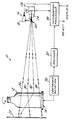
- Apparatus 10 includes a conveyor 14, such as a starwheel conveyor of the type illustrated in above-noted U. S. Patent No. 4,601,395, for conveying containers 12 along an arcuate path to and through an inspection station at which apparatus 10 is disposed.
- a light source 16 in the form of one or more light bulbs 18 is positioned to direct light energy onto a beam splitter 20, from which a portion of the light energy is reflected along an optical axis to and through the container 12 under inspection.
- a retroreflector 22 is positioned on the opposing side of container 12 to reflect the light energy incident thereon back through container 12 and along the same optical axis onto beam splitter 20. A portion of this reflected light energy is transmitted through beam splitter 20 to a lens system 24 having an entrance pupil disposed at the conjugate image of light source 16. Light energy is directed by system 24 onto an array sensor 26, which together with lens system 24 forms a light sensing camera 28.
- Container 12 at the inspection station of apparatus 10 is coupled to a suitable device 30, such as a motor and drive wheel, for rotating container 12 about its axis during the inspection process.
- An encoder 32 is coupled to container rotation device 30 for providing a signal to an information processor 34 indicative of increments of container rotation, either directly as a function of angular increments of container rotation, or indirectly as a function of time increments during which container 12 is rotated at nominally constant angular velocity.
- Information processor 34 is coupled to camera 28 for scanning array sensor 26 at increments of container rotation, and thereby obtaining a two-dimensional image of the container and of light source 16 as viewed through the container.
- Information processor 34 provides outputs to a suitable display, and to a suitable mechanism for rejecting a container 12 in which commercial variations exceed a desirable level.
- Retroreflector 22 which may comprise a micro-corner cube sheet, a glass bead screen or a glass bead reflective paint on a substrate, is characterized by the fact that light energy incident thereon is nominally reflected back on itself along the path of incidence.
- Each light ray that travels through container 12 is refracted or bent according to the exact path that it travels as a function of sidewall geometry, as well as a function of any refractive variations that the ray encounters.
- Each ray (that is not blocked by an opaque variation) strikes reflector 22, and is nominally reflected back along its incoming path.
- Each ray then strikes the container, is refracted by the container along its original path of incidence, and then is directed onto camera sensor 26.
- retroreflector 22 can be provided in the form of a very thin sheet, greatly increasing the amount of space available within the starwheel conveyor diameter and permitting use of smaller starwheel diameters.
- the inspection apparatus of the present invention has been found to operate well in detecting internal and external ribbon tears, stones, edges of blisters, lap marks and bad blowouts. Any location on the container where there is an abrupt thickness change appears dark at camera 28.
- Information processor 34 may employ any suitable technique for sensing dark spots in the camera image.
Landscapes
- Physics & Mathematics (AREA)
- Health & Medical Sciences (AREA)
- Life Sciences & Earth Sciences (AREA)
- Chemical & Material Sciences (AREA)
- Analytical Chemistry (AREA)
- Biochemistry (AREA)
- General Health & Medical Sciences (AREA)
- General Physics & Mathematics (AREA)
- Immunology (AREA)
- Pathology (AREA)
- Investigating Materials By The Use Of Optical Means Adapted For Particular Applications (AREA)
- Optical Elements Other Than Lenses (AREA)
- Investigating Or Analysing Materials By Optical Means (AREA)
- Optical Measuring Cells (AREA)
- Radar Systems Or Details Thereof (AREA)
- Air Conditioning Control Device (AREA)
- Selective Calling Equipment (AREA)
- Testing, Inspecting, Measuring Of Stereoscopic Televisions And Televisions (AREA)
Abstract
Description
Claims (5)
- An apparatus for detecting defects in shaped articles, comprisingcharacterized in thata light source (16),a beam splitter (20),a retroreflector (22),light sensing means (28) comprising an array sensor (26) andinformation processing means (34) coupled to said sensing means,wherein said light source (16) and said light sensing means (28) are arranged on a first side of the article to be tested, and said retroreflector (22) is arranged on a second side opposite to the first side, said light source (16) and said light sensing means (28) being respectively disposed to transmit and receive light energy along a common optical axis,said shaped articles are hollow transparent containers (12), the sidewalls thereof are to be inspected,means (14) for conveying said containers (12) along a path to an inspection station and means (30) for rotating each a container (12) about its axis at said inspection station are provided,said information processing means (34) includes means for scanning said array sensor (26) to develop a two-dimensional image of a respective portion on said first side of said rotating container which is just illuminated by said light source (16), andlight rays (36, 38, 40, 42) that encounter mild refraction due to container geometry and mild refractive variations in the container are reflected by said retroreflector (22) along the path of incidence back through the container (12) onto said sensing means (26), while light rays (42) that encounter stronger refraction due to greater refractive variations or encounter opaque variations are not reflected by said retroreflector (22) along the path of incidence onto said sensing means (26) thereby appearing in said two-dimensional image at said sensing means (26) as a dark spot against a light background so that said information processing means (34) functions as a defect detecting means.
- The apparatus set forth in claim 1 wherein said light sensing means (28) includes a lens system (24) disposed at the conjugate image of the light source (16).
- The apparatus set forth in claim 1 or 2 wherein said conveying means (14) comprises a starwheel conveyor for conveying the container (12) along an arcuate path through said inspection station, and wherein said retroreflector means (22) is disposed within said arcuate path.
- The apparatus set forth in any of claims 1 to 3 wherein an encoder (32) is coupled to said rotating means (30) and provides a rotational signal to said variation detecting means (34).
- A method of inspecting transparent containers for defects that affect optical properties of the containers, comprising the steps of:(a) directing light energy through a container (12) such that individual light rays (36, 38, 40, 42) travel along paths that depend on optical properties of the container (12),(b) reflecting the light energy back through the container in such a way that individual light rays nominally travel in reverse direction along the same light paths, and(c) detecting form or transmission variations in the container as a function of intensity of light energy reflected back through the container, and(d) rotating the respective container (12) at an inspection station so as to detect succeeding defects in the sidewalls of the rotating container.
Applications Claiming Priority (2)
| Application Number | Priority Date | Filing Date | Title |
|---|---|---|---|
| US901009 | 1992-06-19 | ||
| US07/901,009 US5233186A (en) | 1992-06-19 | 1992-06-19 | Inspection of transparent containers with opposing reflection means |
Publications (2)
| Publication Number | Publication Date |
|---|---|
| EP0574890A1 EP0574890A1 (en) | 1993-12-22 |
| EP0574890B1 true EP0574890B1 (en) | 1999-01-27 |
Family
ID=25413464
Family Applications (1)
| Application Number | Title | Priority Date | Filing Date |
|---|---|---|---|
| EP93109569A Expired - Lifetime EP0574890B1 (en) | 1992-06-19 | 1993-06-16 | Inspection of transparent containers with opposing reflection means |
Country Status (12)
| Country | Link |
|---|---|
| US (1) | US5233186A (en) |
| EP (1) | EP0574890B1 (en) |
| JP (1) | JPH07122618B2 (en) |
| AT (1) | ATE176322T1 (en) |
| AU (1) | AU658745B2 (en) |
| BR (1) | BR9302403A (en) |
| CA (1) | CA2098260C (en) |
| DE (1) | DE69323242T2 (en) |
| DK (1) | DK0574890T3 (en) |
| ES (1) | ES2127230T3 (en) |
| GR (1) | GR3030039T3 (en) |
| MX (1) | MX9303602A (en) |
Cited By (1)
| Publication number | Priority date | Publication date | Assignee | Title |
|---|---|---|---|---|
| DE102014217771B4 (en) | 2014-09-05 | 2023-05-04 | Fraunhofer-Gesellschaft zur Förderung der angewandten Forschung e.V. | Device and method for quality control of transparent objects |
Families Citing this family (24)
| Publication number | Priority date | Publication date | Assignee | Title |
|---|---|---|---|---|
| US5369713A (en) * | 1992-07-09 | 1994-11-29 | Schwartz; Nira | Inspection method using area of interest (AOI) analysis |
| DE4337707A1 (en) * | 1993-11-05 | 1995-05-11 | Ulrich Dr Luebbert | Arrangement for lighting and illustration |
| EP0657732A1 (en) * | 1993-12-06 | 1995-06-14 | Elpatronic Ag | Method and device for the optical inspection of a transparent part of a container, especially the mouth |
| GB2288016B (en) * | 1994-03-31 | 1998-05-13 | Tomra Systems As | Device for generating,detecting and recognizing a contour image of a liquid container |
| FR2722574B1 (en) * | 1994-07-12 | 1996-10-04 | Verreries Souchon Neuvesel Sa | METHOD AND DEVICE FOR DETECTING, BY PROCESSING IMAGE SEQUENCES, DEFECTS REFLECTING LIGHT AND PRESENTED BY A TRANSPARENT HOLLOW OBJECT |
| US5442446A (en) | 1994-08-19 | 1995-08-15 | Owens-Brockaway Glass Container Inc. | Inspection of transparent containers |
| US6166813A (en) * | 1997-04-18 | 2000-12-26 | Georgia Tech Research Corporation | Retroreflectometer and method for measuring retroreflectivity of materials |
| US7655586B1 (en) * | 2003-05-29 | 2010-02-02 | Pentron Ceramics, Inc. | Dental restorations using nanocrystalline materials and methods of manufacture |
| US6497324B1 (en) * | 2000-06-07 | 2002-12-24 | Mss, Inc. | Sorting system with multi-plexer |
| US6469126B1 (en) | 2000-12-21 | 2002-10-22 | E. I. Du Pont De Nmeours And Company | Melt-processible, thermoplastic random copolyimides having recoverable crystallinity and associated processes |
| DE10339473A1 (en) * | 2003-08-27 | 2005-03-24 | Seidenader Maschinenbau Gmbh | Device for testing products |
| JP4487042B2 (en) * | 2003-12-16 | 2010-06-23 | レーザーテック株式会社 | Optical apparatus, inspection apparatus, and inspection method |
| US7438192B1 (en) * | 2004-05-28 | 2008-10-21 | Owens-Brockway Glass Container Inc. | Electronic control system for container indexing and inspection apparatus |
| US7595870B2 (en) * | 2004-11-10 | 2009-09-29 | Owens-Brockway Glass Container Inc. | Optical inspection of container walls |
| US7148961B1 (en) | 2004-11-10 | 2006-12-12 | Owens-Brockway Glass Container Inc. | Container sidewall inspection |
| US8170322B2 (en) * | 2006-03-22 | 2012-05-01 | Jadak Llc | Optical imaging system and method using a reflective background |
| JP4847187B2 (en) * | 2006-04-11 | 2011-12-28 | エーザイマシナリー株式会社 | Inspection apparatus and inspection method |
| JP2011503573A (en) * | 2007-11-07 | 2011-01-27 | トムラ・システムズ・エイ・エス・エイ | Apparatus, optical unit and device used for detecting symmetrical objects |
| KR101428666B1 (en) * | 2012-11-30 | 2014-08-08 | 주식회사 케이씨텍 | Apparatus for monitoring an alien substance in pipeline |
| FR3008206B1 (en) * | 2013-07-02 | 2017-04-21 | Guillaume Bathelet | SYSTEM FOR INSPECTING AN AT LEAST TRANSLUCENT OBJECT HAVING AT LEAST ONE MARKING |
| EP3209571B2 (en) | 2014-11-27 | 2022-02-23 | Makro Labelling S.r.l. | Machine and method for orienting containers |
| JP6434806B2 (en) * | 2014-12-25 | 2018-12-05 | アサヒビール株式会社 | Inspection equipment and filling equipment |
| WO2017095702A1 (en) * | 2015-12-04 | 2017-06-08 | Carefusion 303, Inc. | Label reader for automatic drug compounder |
| JP7129456B2 (en) * | 2019-11-15 | 2022-09-01 | エフ ホフマン-ラ ロッシュ アクチェン ゲゼルシャフト | Apparatus for characterizing laboratory sample containers, laboratory automation system, and method for characterizing laboratory sample containers |
Citations (3)
| Publication number | Priority date | Publication date | Assignee | Title |
|---|---|---|---|---|
| US4310242A (en) * | 1980-04-01 | 1982-01-12 | The United States Of America As Represented By The Secretary Of The Air Force | Field test unit for windscreen optical evaluation |
| EP0152894A2 (en) * | 1984-02-20 | 1985-08-28 | Siemens Aktiengesellschaft | Device for optically detecting local inhomogeneities in the structure of tested objects |
| WO1985003776A1 (en) * | 1984-02-14 | 1985-08-29 | Diffracto Ltd. | Panel surface flaw inspection |
Family Cites Families (22)
| Publication number | Priority date | Publication date | Assignee | Title |
|---|---|---|---|---|
| US2429066A (en) * | 1945-08-01 | 1947-10-14 | Gen Electric | Optical transparent film thickness gauge |
| CH465269A (en) * | 1967-06-15 | 1968-11-15 | Emhart Zuerich Sa | Device for the optical inspection of glass objects for cracks |
| US3628872A (en) * | 1969-11-06 | 1971-12-21 | Baxter Laboratories Inc | Spectrophotometric test apparatus and method employing retroflective means |
| US3932763A (en) * | 1974-07-29 | 1976-01-13 | Sensor Technology, Inc. | Detector for tubular transparent article |
| US4207467A (en) * | 1978-09-05 | 1980-06-10 | Laser Precision Corp. | Film measuring apparatus and method |
| JPS56117154A (en) * | 1980-02-21 | 1981-09-14 | Hajime Sangyo Kk | Inspecting apparatus of flaw |
| US4455086A (en) * | 1982-02-09 | 1984-06-19 | Sira Institute Limited | Optical test apparatus for examining an object |
| FR2524349B1 (en) * | 1982-04-01 | 1986-02-28 | Renault | METHOD AND DEVICE FOR IDENTIFYING AND / OR LOCATING PARTS TRANSPORTED BY A CONVEYOR |
| US4863268A (en) * | 1984-02-14 | 1989-09-05 | Diffracto Ltd. | Diffractosight improvements |
| US4920385A (en) * | 1984-02-14 | 1990-04-24 | Diffracto Ltd. | Panel surface flaw inspection |
| GB2157824B (en) * | 1984-04-19 | 1988-09-14 | Owens Illinois Inc | Inspecting and sorting of glass containers |
| US4601395A (en) * | 1984-04-23 | 1986-07-22 | Owens-Illinois, Inc. | Inspecting and sorting of glass containers |
| US4610542A (en) * | 1984-11-16 | 1986-09-09 | Owens-Illinois, Inc. | System for detecting selective refractive defects in transparent articles |
| JPS6212845A (en) * | 1985-07-10 | 1987-01-21 | Kirin Brewery Co Ltd | Detecting device for defect on screwed port part of bottle |
| JPS6269154A (en) * | 1985-09-21 | 1987-03-30 | Hajime Sangyo Kk | Defect inspection instrument for mouth of bottle |
| ZA875450B (en) * | 1986-07-28 | 1988-04-27 | Saint Gobain Cinematique | Inspection of transparent bodies |
| JPS63304146A (en) * | 1987-06-04 | 1988-12-12 | Kirin Brewery Co Ltd | Inspecting device for drum part of bottle |
| NL8800866A (en) * | 1988-04-05 | 1989-11-01 | Thomassen & Drijver | INSPECTION DEVICE. |
| CH679698A5 (en) * | 1989-10-06 | 1992-03-31 | Elpatronic Ag | |
| US5045688A (en) * | 1989-12-04 | 1991-09-03 | Coors Brewing Company | Method and apparatus for inspection of bottle thread having a unitary image plane |
| US5041726A (en) * | 1990-06-11 | 1991-08-20 | Hughes Aircraft Company | Infrared holographic defect detector |
| US5071127A (en) * | 1990-11-05 | 1991-12-10 | Bromley Incorporated | Coin bowling game |
-
1992
- 1992-06-19 US US07/901,009 patent/US5233186A/en not_active Expired - Lifetime
-
1993
- 1993-06-11 CA CA002098260A patent/CA2098260C/en not_active Expired - Lifetime
- 1993-06-15 AU AU41256/93A patent/AU658745B2/en not_active Expired
- 1993-06-16 MX MX9303602A patent/MX9303602A/en unknown
- 1993-06-16 EP EP93109569A patent/EP0574890B1/en not_active Expired - Lifetime
- 1993-06-16 AT AT93109569T patent/ATE176322T1/en active
- 1993-06-16 DE DE69323242T patent/DE69323242T2/en not_active Expired - Lifetime
- 1993-06-16 DK DK93109569T patent/DK0574890T3/en active
- 1993-06-16 ES ES93109569T patent/ES2127230T3/en not_active Expired - Lifetime
- 1993-06-17 JP JP5169815A patent/JPH07122618B2/en not_active Expired - Lifetime
- 1993-06-18 BR BR9302403A patent/BR9302403A/en not_active IP Right Cessation
-
1999
- 1999-04-23 GR GR990401116T patent/GR3030039T3/en unknown
Patent Citations (3)
| Publication number | Priority date | Publication date | Assignee | Title |
|---|---|---|---|---|
| US4310242A (en) * | 1980-04-01 | 1982-01-12 | The United States Of America As Represented By The Secretary Of The Air Force | Field test unit for windscreen optical evaluation |
| WO1985003776A1 (en) * | 1984-02-14 | 1985-08-29 | Diffracto Ltd. | Panel surface flaw inspection |
| EP0152894A2 (en) * | 1984-02-20 | 1985-08-28 | Siemens Aktiengesellschaft | Device for optically detecting local inhomogeneities in the structure of tested objects |
Cited By (1)
| Publication number | Priority date | Publication date | Assignee | Title |
|---|---|---|---|---|
| DE102014217771B4 (en) | 2014-09-05 | 2023-05-04 | Fraunhofer-Gesellschaft zur Förderung der angewandten Forschung e.V. | Device and method for quality control of transparent objects |
Also Published As
| Publication number | Publication date |
|---|---|
| BR9302403A (en) | 1994-01-11 |
| MX9303602A (en) | 1993-12-01 |
| US5233186A (en) | 1993-08-03 |
| JPH0658888A (en) | 1994-03-04 |
| DK0574890T3 (en) | 1999-09-13 |
| ATE176322T1 (en) | 1999-02-15 |
| DE69323242D1 (en) | 1999-03-11 |
| ES2127230T3 (en) | 1999-04-16 |
| CA2098260A1 (en) | 1993-12-20 |
| JPH07122618B2 (en) | 1995-12-25 |
| AU4125693A (en) | 1993-12-23 |
| AU658745B2 (en) | 1995-04-27 |
| CA2098260C (en) | 2005-10-25 |
| GR3030039T3 (en) | 1999-07-30 |
| EP0574890A1 (en) | 1993-12-22 |
| DE69323242T2 (en) | 1999-08-12 |
Similar Documents
| Publication | Publication Date | Title |
|---|---|---|
| EP0574890B1 (en) | Inspection of transparent containers with opposing reflection means | |
| CN1114100C (en) | Method and apparatus for optical inspection of transparent containers using infrared and polarized visible light | |
| EP0957355B1 (en) | Optical inspection of transparent containers using two cameras and a single light source | |
| EP0878705B1 (en) | Container sealing surface area inspection | |
| US4959537A (en) | Method and apparatus for inspecting transparent containers | |
| EP0676635B1 (en) | Inspection of translucent containers | |
| US4606634A (en) | System for detecting selective refractive defects in transparent articles | |
| EP1812788B1 (en) | Optical inspection of container walls | |
| US4610542A (en) | System for detecting selective refractive defects in transparent articles | |
| JP3011397B2 (en) | Inspection method and device for transparent container | |
| CA2132111C (en) | Inspection of translucent containers | |
| US5637864A (en) | Optical inspection of translucent containers for vertical checks and split seams in the container sidewalls | |
| CN85101640A (en) | The detection system of refractive power defective in the transparent substance | |
| US5243400A (en) | Inspection of transparent containers | |
| JPH10185828A (en) | Method and device for inspecting defect of transparent flat body surface | |
| MXPA98010792A (en) | Optic inspection of transparent containers using infrared and polarized light | |
| MXPA99004327A (en) | Optic inspection of transparent containers using two cameras and a single source of |
Legal Events
| Date | Code | Title | Description |
|---|---|---|---|
| PUAI | Public reference made under article 153(3) epc to a published international application that has entered the european phase |
Free format text: ORIGINAL CODE: 0009012 |
|
| AK | Designated contracting states |
Kind code of ref document: A1 Designated state(s): AT BE CH DE DK ES FR GB GR IE IT LI LU MC NL PT SE |
|
| 17P | Request for examination filed |
Effective date: 19940514 |
|
| 17Q | First examination report despatched |
Effective date: 19960702 |
|
| GRAG | Despatch of communication of intention to grant |
Free format text: ORIGINAL CODE: EPIDOS AGRA |
|
| GRAG | Despatch of communication of intention to grant |
Free format text: ORIGINAL CODE: EPIDOS AGRA |
|
| GRAH | Despatch of communication of intention to grant a patent |
Free format text: ORIGINAL CODE: EPIDOS IGRA |
|
| GRAH | Despatch of communication of intention to grant a patent |
Free format text: ORIGINAL CODE: EPIDOS IGRA |
|
| GRAA | (expected) grant |
Free format text: ORIGINAL CODE: 0009210 |
|
| AK | Designated contracting states |
Kind code of ref document: B1 Designated state(s): AT BE CH DE DK ES FR GB GR IE IT LI LU MC NL PT SE |
|
| REF | Corresponds to: |
Ref document number: 176322 Country of ref document: AT Date of ref document: 19990215 Kind code of ref document: T |
|
| REG | Reference to a national code |
Ref country code: CH Ref legal event code: EP |
|
| ET | Fr: translation filed | ||
| REG | Reference to a national code |
Ref country code: IE Ref legal event code: FG4D |
|
| REF | Corresponds to: |
Ref document number: 69323242 Country of ref document: DE Date of ref document: 19990311 |
|
| REG | Reference to a national code |
Ref country code: ES Ref legal event code: FG2A Ref document number: 2127230 Country of ref document: ES Kind code of ref document: T3 |
|
| REG | Reference to a national code |
Ref country code: CH Ref legal event code: NV Representative=s name: BOVARD AG PATENTANWAELTE |
|
| REG | Reference to a national code |
Ref country code: PT Ref legal event code: SC4A Free format text: AVAILABILITY OF NATIONAL TRANSLATION Effective date: 19990326 |
|
| REG | Reference to a national code |
Ref country code: DK Ref legal event code: T3 |
|
| PLBE | No opposition filed within time limit |
Free format text: ORIGINAL CODE: 0009261 |
|
| STAA | Information on the status of an ep patent application or granted ep patent |
Free format text: STATUS: NO OPPOSITION FILED WITHIN TIME LIMIT |
|
| 26N | No opposition filed | ||
| REG | Reference to a national code |
Ref country code: GB Ref legal event code: IF02 |
|
| PGFP | Annual fee paid to national office [announced via postgrant information from national office to epo] |
Ref country code: LU Payment date: 20070326 Year of fee payment: 15 |
|
| PGFP | Annual fee paid to national office [announced via postgrant information from national office to epo] |
Ref country code: MC Payment date: 20070530 Year of fee payment: 15 |
|
| PG25 | Lapsed in a contracting state [announced via postgrant information from national office to epo] |
Ref country code: MC Free format text: LAPSE BECAUSE OF NON-PAYMENT OF DUE FEES Effective date: 20080630 |
|
| PG25 | Lapsed in a contracting state [announced via postgrant information from national office to epo] |
Ref country code: LU Free format text: LAPSE BECAUSE OF NON-PAYMENT OF DUE FEES Effective date: 20080616 |
|
| REG | Reference to a national code |
Ref country code: CH Ref legal event code: PFA Owner name: OWENS-BROCKWAY GLASS CONTAINER INC. Free format text: OWENS-BROCKWAY GLASS CONTAINER INC.#ONE SEA GATE, 30-LDP#TOLEDO, OHIO 43666 (US) -TRANSFER TO- OWENS-BROCKWAY GLASS CONTAINER INC.#ONE SEA GATE, 30-LDP#TOLEDO, OHIO 43666 (US) |
|
| PGFP | Annual fee paid to national office [announced via postgrant information from national office to epo] |
Ref country code: NL Payment date: 20120620 Year of fee payment: 20 Ref country code: CH Payment date: 20120427 Year of fee payment: 20 Ref country code: IE Payment date: 20120529 Year of fee payment: 20 Ref country code: DK Payment date: 20120525 Year of fee payment: 20 |
|
| PGFP | Annual fee paid to national office [announced via postgrant information from national office to epo] |
Ref country code: SE Payment date: 20120607 Year of fee payment: 20 Ref country code: GB Payment date: 20120525 Year of fee payment: 20 Ref country code: FR Payment date: 20120614 Year of fee payment: 20 Ref country code: GR Payment date: 20120530 Year of fee payment: 20 |
|
| PGFP | Annual fee paid to national office [announced via postgrant information from national office to epo] |
Ref country code: IT Payment date: 20120619 Year of fee payment: 20 |
|
| PGFP | Annual fee paid to national office [announced via postgrant information from national office to epo] |
Ref country code: ES Payment date: 20120622 Year of fee payment: 20 Ref country code: BE Payment date: 20120710 Year of fee payment: 20 Ref country code: DE Payment date: 20120629 Year of fee payment: 20 |
|
| PGFP | Annual fee paid to national office [announced via postgrant information from national office to epo] |
Ref country code: PT Payment date: 20120529 Year of fee payment: 20 |
|
| PGFP | Annual fee paid to national office [announced via postgrant information from national office to epo] |
Ref country code: AT Payment date: 20120525 Year of fee payment: 20 |
|
| REG | Reference to a national code |
Ref country code: DK Ref legal event code: EUP |
|
| REG | Reference to a national code |
Ref country code: DE Ref legal event code: R071 Ref document number: 69323242 Country of ref document: DE |
|
| REG | Reference to a national code |
Ref country code: PT Ref legal event code: MM4A Free format text: MAXIMUM VALIDITY LIMIT REACHED Effective date: 20130616 |
|
| REG | Reference to a national code |
Ref country code: NL Ref legal event code: V4 Effective date: 20130616 |
|
| REG | Reference to a national code |
Ref country code: CH Ref legal event code: PL |
|
| BE20 | Be: patent expired |
Owner name: *OWENS-BROCKWAY GLASS CONTAINER INC. Effective date: 20130616 |
|
| REG | Reference to a national code |
Ref country code: GB Ref legal event code: PE20 Expiry date: 20130615 |
|
| PG25 | Lapsed in a contracting state [announced via postgrant information from national office to epo] |
Ref country code: GB Free format text: LAPSE BECAUSE OF EXPIRATION OF PROTECTION Effective date: 20130615 Ref country code: DE Free format text: LAPSE BECAUSE OF EXPIRATION OF PROTECTION Effective date: 20130618 |
|
| REG | Reference to a national code |
Ref country code: AT Ref legal event code: MK07 Ref document number: 176322 Country of ref document: AT Kind code of ref document: T Effective date: 20130616 |
|
| PG25 | Lapsed in a contracting state [announced via postgrant information from national office to epo] |
Ref country code: PT Free format text: LAPSE BECAUSE OF EXPIRATION OF PROTECTION Effective date: 20130625 |
|
| REG | Reference to a national code |
Ref country code: GR Ref legal event code: MA Ref document number: 990401116 Country of ref document: GR Effective date: 20130617 |
|
| REG | Reference to a national code |
Ref country code: IE Ref legal event code: MK9A |
|
| PG25 | Lapsed in a contracting state [announced via postgrant information from national office to epo] |
Ref country code: IE Free format text: LAPSE BECAUSE OF EXPIRATION OF PROTECTION Effective date: 20130616 |
|
| REG | Reference to a national code |
Ref country code: ES Ref legal event code: FD2A Effective date: 20140828 |
|
| PG25 | Lapsed in a contracting state [announced via postgrant information from national office to epo] |
Ref country code: ES Free format text: LAPSE BECAUSE OF EXPIRATION OF PROTECTION Effective date: 20130617 |