EP0574645B1 - A method for fixing heat exchange elements to an end plate and a tool for conforming to a circular cross-section the end of a tube of oblong cross-section - Google Patents
A method for fixing heat exchange elements to an end plate and a tool for conforming to a circular cross-section the end of a tube of oblong cross-section Download PDFInfo
- Publication number
- EP0574645B1 EP0574645B1 EP19920830307 EP92830307A EP0574645B1 EP 0574645 B1 EP0574645 B1 EP 0574645B1 EP 19920830307 EP19920830307 EP 19920830307 EP 92830307 A EP92830307 A EP 92830307A EP 0574645 B1 EP0574645 B1 EP 0574645B1
- Authority
- EP
- European Patent Office
- Prior art keywords
- section
- cross
- tube
- tubes
- cavity
- Prior art date
- Legal status (The legal status is an assumption and is not a legal conclusion. Google has not performed a legal analysis and makes no representation as to the accuracy of the status listed.)
- Expired - Lifetime
Links
Images



Classifications
-
- F—MECHANICAL ENGINEERING; LIGHTING; HEATING; WEAPONS; BLASTING
- F28—HEAT EXCHANGE IN GENERAL
- F28F—DETAILS OF HEAT-EXCHANGE AND HEAT-TRANSFER APPARATUS, OF GENERAL APPLICATION
- F28F9/00—Casings; Header boxes; Auxiliary supports for elements; Auxiliary members within casings
- F28F9/02—Header boxes; End plates
- F28F9/04—Arrangements for sealing elements into header boxes or end plates
- F28F9/16—Arrangements for sealing elements into header boxes or end plates by permanent joints, e.g. by rolling
- F28F9/165—Arrangements for sealing elements into header boxes or end plates by permanent joints, e.g. by rolling by using additional preformed parts, e.g. sleeves, gaskets
-
- B—PERFORMING OPERATIONS; TRANSPORTING
- B21—MECHANICAL METAL-WORKING WITHOUT ESSENTIALLY REMOVING MATERIAL; PUNCHING METAL
- B21D—WORKING OR PROCESSING OF SHEET METAL OR METAL TUBES, RODS OR PROFILES WITHOUT ESSENTIALLY REMOVING MATERIAL; PUNCHING METAL
- B21D41/00—Application of procedures in order to alter the diameter of tube ends
-
- B—PERFORMING OPERATIONS; TRANSPORTING
- B21—MECHANICAL METAL-WORKING WITHOUT ESSENTIALLY REMOVING MATERIAL; PUNCHING METAL
- B21D—WORKING OR PROCESSING OF SHEET METAL OR METAL TUBES, RODS OR PROFILES WITHOUT ESSENTIALLY REMOVING MATERIAL; PUNCHING METAL
- B21D53/00—Making other particular articles
- B21D53/02—Making other particular articles heat exchangers or parts thereof, e.g. radiators, condensers fins, headers
- B21D53/08—Making other particular articles heat exchangers or parts thereof, e.g. radiators, condensers fins, headers of both metal tubes and sheet metal
- B21D53/085—Making other particular articles heat exchangers or parts thereof, e.g. radiators, condensers fins, headers of both metal tubes and sheet metal with fins places on zig-zag tubes or parallel tubes
Definitions
- the present invention relates to the manufacture of heat-exchangers, particularly for motor vehicles, and is concerned with a method of fixing an end plate to a heat-exchange system including a plurality of tubes with elongate cross-sections, in which the ends of the tubes are shaped so as to have circular cross-sections before being inserted in sealing collars of circular cross-section disposed in respective holes in the end plate, and in which the tubes are fixed to the end plate by the radial expansion of their ends after they have been fitted in the sealing collars.
- a method of shaping the end of a metal heat-exchanger tube of elongate cross-section to give it a circular cross-section is known from the French patent No. 2,462,215.
- the method described in this document consists of two steps, that is, one step in which the end of the tube undergoes radial compression, and another step in which a punch is force-fitted into the end. If the radial deformation is effected first, the end of the tube is compressed between two jaws which are movable perpendicular to the axis of the tube along the major axis of its cross-section. If the punch is force-fitted in the end of the tube first, the subsequent radial compression is effected by means of a bush with a flared end which is movable along the axis of the tube.
- the two-step method of shaping the ends of the tubes has various disadvantages.
- radial compression effected by jaws movable perpendicular to the axis of the tube cannot easily be used for heat exchangers with two or more rows of tubes, since it would require too much space between the rows.
- the radial deformation is effected by means of a bush slidable along the axis of the tube, difficulties are encountered in removing the tools from the ends of the tubes since, upon completion of the shaping, both the bush and the punch are coupled with the end of the tube at the same time.
- the shaping tools and machines are more complex than with a single-step shaping method.
- the present invention provides for a method with the features of claim 1 respectively a tool with the features of claim 2.
- the method of the invention is quicker, requires simpler tools, and involves a simplification of the machines which move the tools since the machines have to effect only one movement instead of the two movements needed for two-step methods.
- a heat-exchange system indicated 10 includes a plurality of tubes 12 having flat cross-sections each constituted by two straight lines 14 and two semicircular connecting portions 16.
- the maximum and minimum dimensions of the cross-section of each tube 12 are indicated a and b ; the ratio a / b is of the order of 3:1.
- the tubes 12 are arranged in two parallel rows, 18, 20.
- the tubes 12 are fixed to metal fins 22 disposed one above another along the longitudinal axes of the tubes 12.
- the fins 22 have holes, with shapes corresponding to the profiles of the tubes 12, in which the tubes 12 are fitted with slight radial clearance.
- the tubes 12 are fixed to the fins 22, in known manner, by the expansion of the tubes 12.
- the ends 24 of the tubes are fixed to an end plate 26 ( Figures 3 and 4) which constitutes the base wall of a header tank (not shown) for collecting the cooling liquid which circulates in the tubes 12.
- the end plate 26 has a plurality of holes 28 with circular cross-sections, in which sealing collars 30 of a gasket 32 of elastomeric material are disposed.
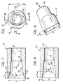
- each tool 34 is constituted by a metal body having a cavity 36 with an opening 38. At a distance e from the opening 38, along the axis of the cavity 36, the cross-section of the cavity 36 is circular.
- a portion 40 of the cavity 36 has a tapered wall which is inclined at 2-3 o to the longitudinal axis of the cavity 36. The length of the portion 40 is equal to the desired length of the circular cross-sectioned end portion of each tube 12.
- a connecting portion 42 of radius R which gives the end edge of the tube a perfectly circular cross-section and makes it easier to fit in a hole in a sealing collar 30 by forming a kind of lead-in.
- the cavity 36 communicates with a hole 44 for fixing the tool 34 to a frame (not shown) which moves the tools 34 along the line indicated by the arrow 46 in Figure 1.
- the opening 38 has an oval cross-section the maximum dimension c which is slightly greater than the maximum dimension a of the cross-section of the undeformed tube 12.
- the minimum dimension, indicated d , of the opening 38 is equal to or greater than the maximum diameter of the circular cross-sectioned portion 40 of the cavity 36.
- the opening 38 is connected to the tapered portion 40 of the cavity 36 by means of a connecting region having two opposed surfaces 50 which, in use, exert gradual pressure on the walls 16 of the tube 12 which have the smallest radius of curvature.
- the ends 24 of the tubes 12 are shaped by being force-fitted in the respective cavities 36 of the tools 34.
- the taper of the portion 40 of each cavity 36 facilitates the removal of the tools 34 upon completion of the shaping.
- Figure 8 shows the end of a tube 12 which has been shaped.
- the tool 34 causes no stretching of the material in the deformed region.
- the perimeter of the end 24 is the same as or slightly shorter than the perimeter of the undeformed portion of the tube 12.
- the ends 24 of the tubes 12 After the ends 24 of the tubes 12 have been shaped by the tools 34, the ends 24 are fitted in the cylindrical holes in the sealing collars 30 with radial clearance (see Figure 3). Punches 52 are then inserted in the ends of the tubes 12 to expand the ends 24 radially against the sealing collars 30. This expansion connects the tubes 12 to the end plate 26 mechanically and in a fluid-tight manner. During the expansion, the edges 24 a of the end 24 are turned over so as to improve the seal resulting from the expansion of the end 24.
Landscapes
- Engineering & Computer Science (AREA)
- Mechanical Engineering (AREA)
- Physics & Mathematics (AREA)
- Thermal Sciences (AREA)
- General Engineering & Computer Science (AREA)
- Heat-Exchange Devices With Radiators And Conduit Assemblies (AREA)
Description
- The present invention relates to the manufacture of heat-exchangers, particularly for motor vehicles, and is concerned with a method of fixing an end plate to a heat-exchange system including a plurality of tubes with elongate cross-sections, in which the ends of the tubes are shaped so as to have circular cross-sections before being inserted in sealing collars of circular cross-section disposed in respective holes in the end plate, and in which the tubes are fixed to the end plate by the radial expansion of their ends after they have been fitted in the sealing collars.
- In a heat-exchanger of the type specified above, it is necessary to shape the ends of the tubes in order to achieve an effective and durable connection between the end plates and the ends of the tubes. Since the end plates serve for the attachment of the header tanks containing the liquid which circulates in the heat-exchange system, their connection to the ends of the tubes must be quite firm mechanically as well as being liquid-tight.
- Experience has shown that, with tubes of elongate cross-section (particularly with a very high ratio between the maximum and minimum dimensions of the cross-section of the tube), it is very difficult to connect the ends of the tubes to the header plates in a mechanically firm and liquid-tight manner simply by the enlargement (expansion) of the ends of the tubes. In fact, in this case, a firm anchorage of the walls of the tubes, which extend parallel to the major axes of their cross-sections, is rather problematical. Thus, in spite of the enlargement of the ends of the tubes, there is a danger of the walls of the tubes breaking parallel to their major axes, making the mechanical connection and the sealing of the heat-exchanger insecure.
- A method of shaping the end of a metal heat-exchanger tube of elongate cross-section to give it a circular cross-section is known from the French patent No. 2,462,215. The method described in this document consists of two steps, that is, one step in which the end of the tube undergoes radial compression, and another step in which a punch is force-fitted into the end. If the radial deformation is effected first, the end of the tube is compressed between two jaws which are movable perpendicular to the axis of the tube along the major axis of its cross-section. If the punch is force-fitted in the end of the tube first, the subsequent radial compression is effected by means of a bush with a flared end which is movable along the axis of the tube.
- For practical purposes, the two-step method of shaping the ends of the tubes has various disadvantages. In particular, radial compression effected by jaws movable perpendicular to the axis of the tube cannot easily be used for heat exchangers with two or more rows of tubes, since it would require too much space between the rows. In the solution in which the radial deformation is effected by means of a bush slidable along the axis of the tube, difficulties are encountered in removing the tools from the ends of the tubes since, upon completion of the shaping, both the bush and the punch are coupled with the end of the tube at the same time. In any case, with the two-step shaping method, the shaping tools and machines are more complex than with a single-step shaping method.
- In a method known from the British document No. 2,055,064 for shaping the end of a metal tube having an elongate cross-section to give it a circular cross-section, the shaping is effected in a single step by means of a punch having a cylindrical body which is force-fitted in the end of the tube. This solution is unsuitable for tubes with ratios of the order of 3:1 or more between their maximum and minimum diameters. Figure 10 of the appended drawings shows the configuration which a tube 1 with a ratio of the order of 3:1 between its extreme diameters would assume as a result of radial deformation from inside by means of a punch 2. The smaller-radius curves 3 tend to remain undeformed since they have greater rigidity than the rest of the wall. A more even circular cross-section could be achieved with the use of a larger-diameter punch but this would stretch the walls of the tube too much. This stretching would make it difficult to carry out the subsequent step in which the ends of the tubes are fixed to the sealing collars in the base plate by radial expansion. In fact, two successive steps which stretch the walls of the tube considerably increases the risk of the walls breaking. Moreover, larger diameters of the ends of the tubes necessitate more space between the rows of tubes in the exchanger system.
- In order to overcome the aforementioned problems, the present invention provides for a method with the features of claim 1 respectively a tool with the features of claim 2.
- In comparison with two-step shaping methods, the method of the invention is quicker, requires simpler tools, and involves a simplification of the machines which move the tools since the machines have to effect only one movement instead of the two movements needed for two-step methods.
- In comparison with the solution which provides for the end of the tube to be expanded from the inside by means of a punch, there is the advantage that the excessive stretching of the walls of the tube, particularly with a high ratio between the maximum and minimum diameters of its cross-section, is avoided.
- Further characteristics and advantages of the present invention will become clear in the course of the detailed description which follows with reference to the appended drawings, provided purely by way of non-limiting example, in which:
- Figure 1 is a cross-section of a portion of a heat-exchange system during a stage of the method according to the invention,
- Figure 2 is a section taken on the line II-II of Figure 1,
- Figures 3 and 4 are views similar to Figure 1, showing another two steps of the method according to the invention,
- Figure 5 is a plan view of a tool for shaping the ends of the tubes,
- Figures 6 and 7 are sections taken on the lines VI-VI and VII-VII of Figure 5,
- Figure 8 is a perspective view of the end of a tube shaped by the tool of Figure 5,
- Figure 9 is a view taken on the arrow IX of Figure 8, and
- Figure 10, which has already been commented upon above, is a schematic view showing the shaping of a tube by a method of the prior art.
- With reference to the drawings, in Figures 1 and 2, a heat-exchange system, indicated 10, includes a plurality of
tubes 12 having flat cross-sections each constituted by twostraight lines 14 and two semicircular connectingportions 16. The maximum and minimum dimensions of the cross-section of eachtube 12 are indicated a and b; the ratio a/b is of the order of 3:1. In the embodiment shown in the drawings, thetubes 12 are arranged in two parallel rows, 18, 20. - The
tubes 12 are fixed tometal fins 22 disposed one above another along the longitudinal axes of thetubes 12. In known manner, thefins 22 have holes, with shapes corresponding to the profiles of thetubes 12, in which thetubes 12 are fitted with slight radial clearance. Thetubes 12 are fixed to thefins 22, in known manner, by the expansion of thetubes 12. - After the
tubes 12 have been fixed to thefins 22 to form the heat-exchange system 10, theends 24 of the tubes are fixed to an end plate 26 (Figures 3 and 4) which constitutes the base wall of a header tank (not shown) for collecting the cooling liquid which circulates in thetubes 12. With reference to Figures 3 and 4, theend plate 26 has a plurality ofholes 28 with circular cross-sections, in which sealingcollars 30 of agasket 32 of elastomeric material are disposed. - Before the
ends 24 of thetubes 12 are fitted in thesealing collars 30, theends 24 are shaped so as to have circular cross-sections byrespective tools 34, shown in Figures 1 and 5-7. Eachtool 34 is constituted by a metal body having acavity 36 with anopening 38. At a distance e from theopening 38, along the axis of thecavity 36, the cross-section of thecavity 36 is circular. Aportion 40 of thecavity 36 has a tapered wall which is inclined at 2-3o to the longitudinal axis of thecavity 36. The length of theportion 40 is equal to the desired length of the circular cross-sectioned end portion of eachtube 12. At the end of thecavity 36 is a connectingportion 42 of radius R which gives the end edge of the tube a perfectly circular cross-section and makes it easier to fit in a hole in a sealingcollar 30 by forming a kind of lead-in. Thecavity 36 communicates with ahole 44 for fixing thetool 34 to a frame (not shown) which moves thetools 34 along the line indicated by thearrow 46 in Figure 1. Theopening 38 has an oval cross-section the maximum dimension c which is slightly greater than the maximum dimension a of the cross-section of theundeformed tube 12. The minimum dimension, indicated d, of theopening 38 is equal to or greater than the maximum diameter of thecircular cross-sectioned portion 40 of thecavity 36. Theopening 38 is connected to thetapered portion 40 of thecavity 36 by means of a connecting region having twoopposed surfaces 50 which, in use, exert gradual pressure on thewalls 16 of thetube 12 which have the smallest radius of curvature. - The
ends 24 of thetubes 12 are shaped by being force-fitted in therespective cavities 36 of thetools 34. The taper of theportion 40 of eachcavity 36 facilitates the removal of thetools 34 upon completion of the shaping. Figure 8 shows the end of atube 12 which has been shaped. Thetool 34 causes no stretching of the material in the deformed region. Upon completion of the shaping, the perimeter of theend 24 is the same as or slightly shorter than the perimeter of the undeformed portion of thetube 12. - After the
ends 24 of thetubes 12 have been shaped by thetools 34, theends 24 are fitted in the cylindrical holes in thesealing collars 30 with radial clearance (see Figure 3).Punches 52 are then inserted in the ends of thetubes 12 to expand theends 24 radially against the sealingcollars 30. This expansion connects thetubes 12 to theend plate 26 mechanically and in a fluid-tight manner. During the expansion, theedges 24a of theend 24 are turned over so as to improve the seal resulting from the expansion of theend 24. - The method of shaping the ends of the tubes has been described with reference to flat tubes but is intended also to be applicable to tubes having any elongate cross-section, such as, for example, oval, elliptical, ovoidal, or the like.
Claims (4)
- A method of fixing an end plate (26) to a heat-exchange system (10) including a plurality of tubes (12) with elongate cross-sections, in which the ends (24) of the tubes are shaped so as to have circular cross-sections before being fitted in sealing collars (30) of circular cross-section disposed in respective holes (28) in the end plate (26), and in which the tubes (12) are fixed to the end plate (26) by the radial expansion of their ends (24) after they have been fitted in the sealing collars (30), characterised in that the ends (24) of the tubes are shaped in a single step by radial compression from outside, applied by means of a hollow body (34) with a cavity (36) having a cross-section varying from elongate to circular, the hollow body being movable along the axis of the tube and formed so as to exert pressure on the walls (16) of the tube (12) which have the smallest radius of curvature, and in that the ends of the tubes (24) are fitted in the sealing collars (30) without further deformation.
- A tool for performing a method according to Claim 1, for shaping the end of a heat-exchanger tube to give it a circular cross-section, characterised in that it includes a unitary body (34) having an opening (38) which communicates with a cavity (36) the cross-section of which varies along its longitudinal axis, the cross-section of the cavity being elongate near the opening so as to contain the cross-section of the undeformed tube, and being circular a predetermined distance (e) from the opening (38) along the axis of the cavity.
- A tool according to Claim 2, characterised in that the cross-section of the cavity near the opening (38) is oval and has a maximum dimension (c) greater than the maximum dimension (a) of the cross-section of the undeformed tube and a minimum dimension (d) which is equal to or greater than the diameter of the portion of the cavity (36) which has a circular cross-section.
- A tool according to Claim 3, characterised in that the cavity (36) has a portion (40) with a tapered wall of a length, along the axis of the cavity, equal to the desired axial length of the circular cross-sectioned end portion of the tube.
Priority Applications (3)
| Application Number | Priority Date | Filing Date | Title |
|---|---|---|---|
| ES92830307T ES2082437T3 (en) | 1992-06-16 | 1992-06-16 | A METHOD FOR ATTACHING HEAT EXCHANGER ELEMENTS TO A PLATE AND A TOOL FOR CONFORMING A CIRCULAR CROSS SECTION TO AN OBLONGA CROSS SECTION TUBE. |
| DE1992607755 DE69207755T2 (en) | 1992-06-16 | 1992-06-16 | Method of connecting heat exchanger elements to a plate and tool for deforming the pipe end from an elongated average to a circular average |
| EP19920830307 EP0574645B1 (en) | 1992-06-16 | 1992-06-16 | A method for fixing heat exchange elements to an end plate and a tool for conforming to a circular cross-section the end of a tube of oblong cross-section |
Applications Claiming Priority (1)
| Application Number | Priority Date | Filing Date | Title |
|---|---|---|---|
| EP19920830307 EP0574645B1 (en) | 1992-06-16 | 1992-06-16 | A method for fixing heat exchange elements to an end plate and a tool for conforming to a circular cross-section the end of a tube of oblong cross-section |
Publications (2)
| Publication Number | Publication Date |
|---|---|
| EP0574645A1 EP0574645A1 (en) | 1993-12-22 |
| EP0574645B1 true EP0574645B1 (en) | 1996-01-17 |
Family
ID=8212121
Family Applications (1)
| Application Number | Title | Priority Date | Filing Date |
|---|---|---|---|
| EP19920830307 Expired - Lifetime EP0574645B1 (en) | 1992-06-16 | 1992-06-16 | A method for fixing heat exchange elements to an end plate and a tool for conforming to a circular cross-section the end of a tube of oblong cross-section |
Country Status (3)
| Country | Link |
|---|---|
| EP (1) | EP0574645B1 (en) |
| DE (1) | DE69207755T2 (en) |
| ES (1) | ES2082437T3 (en) |
Cited By (2)
| Publication number | Priority date | Publication date | Assignee | Title |
|---|---|---|---|---|
| US11215406B2 (en) | 2013-06-20 | 2022-01-04 | Boustead International Heaters Limited | Waste heat recovery units |
| US11318515B1 (en) | 2021-02-08 | 2022-05-03 | Sigma Corporation | Large diameter pipe rounding tool and method of use |
Families Citing this family (3)
| Publication number | Priority date | Publication date | Assignee | Title |
|---|---|---|---|---|
| KR101735273B1 (en) | 2015-10-07 | 2017-05-15 | (주)디엠피테크 | Apparatus of manufacturing a multi-row refrigerant tube and method of manufacturing the refrigerant tube |
| FR3056735B1 (en) * | 2016-09-28 | 2020-10-23 | Valeo Systemes Thermiques | HEAT EXCHANGER, ESPECIALLY FOR MOTOR VEHICLES |
| FR3056736B1 (en) * | 2016-09-28 | 2019-07-26 | Valeo Systemes Thermiques | THERMAL EXCHANGE BEAM FOR THERMAL EXCHANGER, THERMAL EXCHANGER AND ASSOCIATED ASSEMBLY METHOD |
Family Cites Families (2)
| Publication number | Priority date | Publication date | Assignee | Title |
|---|---|---|---|---|
| US2767605A (en) * | 1953-05-05 | 1956-10-23 | Henry Edward Wiersch | Hand tool for truing pipe ends |
| FR2462214A1 (en) * | 1979-07-26 | 1981-02-13 | Ferodo Sa | PROCESS FOR CONFORMING A TUBE, ESPECIALLY FOR A HEAT EXCHANGER |
-
1992
- 1992-06-16 EP EP19920830307 patent/EP0574645B1/en not_active Expired - Lifetime
- 1992-06-16 DE DE1992607755 patent/DE69207755T2/en not_active Expired - Lifetime
- 1992-06-16 ES ES92830307T patent/ES2082437T3/en not_active Expired - Lifetime
Cited By (2)
| Publication number | Priority date | Publication date | Assignee | Title |
|---|---|---|---|---|
| US11215406B2 (en) | 2013-06-20 | 2022-01-04 | Boustead International Heaters Limited | Waste heat recovery units |
| US11318515B1 (en) | 2021-02-08 | 2022-05-03 | Sigma Corporation | Large diameter pipe rounding tool and method of use |
Also Published As
| Publication number | Publication date |
|---|---|
| ES2082437T3 (en) | 1996-03-16 |
| EP0574645A1 (en) | 1993-12-22 |
| DE69207755D1 (en) | 1996-02-29 |
| DE69207755T2 (en) | 1996-06-20 |
Similar Documents
| Publication | Publication Date | Title |
|---|---|---|
| CA2012043C (en) | Heat exchanger and a method for a liquid-tight mounting of an end plate to an array of heat exchanging elements of the heat exchanger | |
| KR940002832B1 (en) | Manifold and its manufacturing method | |
| US5579832A (en) | Heat exchanger tube, apparatus for forming such a tube, and a heat exchanger comprising such tubes | |
| KR960005791B1 (en) | Method of manufacture of manifolds and manifold provided by such method | |
| US4269267A (en) | Fin and tube assembly and a method of making the assembly | |
| US5119552A (en) | Method for manufacturing header pipe of heat exchanger | |
| EP0576725B1 (en) | Heat exchanger header tube and method of making | |
| US4574444A (en) | Method for the joining of tubular parts in a heat exchanger and tool for practicing the method | |
| KR100437585B1 (en) | Method for assembling a heat exchanger | |
| CS226414B2 (en) | Metal pipe for heat exchangers and method of manufacturing same | |
| US3433300A (en) | Heat exchangers and the method of making same | |
| US4856824A (en) | Method of manufacture of manifolds and manifold provided by such method | |
| JPH06235594A (en) | Heat exchanger with tube handke, particularly tube handle for motor car and manufacture thereof | |
| EP1795853B1 (en) | A heat exchanger and a method of manufacturing the same. | |
| US6186225B1 (en) | Heat exchanger with an integrated tank and head sheet | |
| EP0574645A1 (en) | A method for fixing heat exchange elements to an end plate and a tool for conforming to a circular cross-section the end of a tube of oblong cross-section | |
| WO1999060322A1 (en) | Heat exchanger with an integrated tank and head sheet | |
| EP0584995B1 (en) | Heat exchanger | |
| US3546763A (en) | Heat exchangers and the method of making same | |
| CN114011980A (en) | Production method of finned heat exchanger | |
| US5337477A (en) | Methods and apparatus for forming tubular risers and manifolds including tubular risers | |
| JPH0428438A (en) | Manufacture of heat transfer tube for heat exchanger | |
| US2948054A (en) | Method of fabricating finned heat transfer tubing | |
| US5450667A (en) | Process for fixing a transverse partition in a tubular header of a heat exchanger | |
| US2999304A (en) | Method of manufacturing heat exchangers |
Legal Events
| Date | Code | Title | Description |
|---|---|---|---|
| PUAI | Public reference made under article 153(3) epc to a published international application that has entered the european phase |
Free format text: ORIGINAL CODE: 0009012 |
|
| AK | Designated contracting states |
Kind code of ref document: A1 Designated state(s): DE ES FR GB IT SE |
|
| 17P | Request for examination filed |
Effective date: 19940316 |
|
| 17Q | First examination report despatched |
Effective date: 19950322 |
|
| GRAA | (expected) grant |
Free format text: ORIGINAL CODE: 0009210 |
|
| RAP1 | Party data changed (applicant data changed or rights of an application transferred) |
Owner name: MAGNETI MARELLI CLIMATIZZAZIONE S.R.L. |
|
| AK | Designated contracting states |
Kind code of ref document: B1 Designated state(s): DE ES FR GB IT SE |
|
| RBV | Designated contracting states (corrected) |
Designated state(s): DE ES FR GB IT SE |
|
| ITF | It: translation for a ep patent filed | ||
| REF | Corresponds to: |
Ref document number: 69207755 Country of ref document: DE Date of ref document: 19960229 |
|
| REG | Reference to a national code |
Ref country code: ES Ref legal event code: FG2A Ref document number: 2082437 Country of ref document: ES Kind code of ref document: T3 |
|
| ET | Fr: translation filed | ||
| PLBE | No opposition filed within time limit |
Free format text: ORIGINAL CODE: 0009261 |
|
| 26N | No opposition filed | ||
| EUG | Se: european patent has lapsed | ||
| REG | Reference to a national code |
Ref country code: GB Ref legal event code: IF02 |
|
| PGFP | Annual fee paid to national office [announced via postgrant information from national office to epo] |
Ref country code: SE Payment date: 20060607 Year of fee payment: 15 |
|
| EUG | Se: european patent has lapsed | ||
| PG25 | Lapsed in a contracting state [announced via postgrant information from national office to epo] |
Ref country code: SE Free format text: LAPSE BECAUSE OF NON-PAYMENT OF DUE FEES Effective date: 20070617 |
|
| PGFP | Annual fee paid to national office [announced via postgrant information from national office to epo] |
Ref country code: IT Payment date: 20090626 Year of fee payment: 17 |
|
| PGFP | Annual fee paid to national office [announced via postgrant information from national office to epo] |
Ref country code: ES Payment date: 20090713 Year of fee payment: 18 |
|
| PGFP | Annual fee paid to national office [announced via postgrant information from national office to epo] |
Ref country code: GB Payment date: 20090624 Year of fee payment: 18 |
|
| GBPC | Gb: european patent ceased through non-payment of renewal fee |
Effective date: 20100616 |
|
| PG25 | Lapsed in a contracting state [announced via postgrant information from national office to epo] |
Ref country code: IT Free format text: LAPSE BECAUSE OF NON-PAYMENT OF DUE FEES Effective date: 20090616 |
|
| REG | Reference to a national code |
Ref country code: ES Ref legal event code: FD2A Effective date: 20110715 |
|
| PG25 | Lapsed in a contracting state [announced via postgrant information from national office to epo] |
Ref country code: ES Free format text: LAPSE BECAUSE OF NON-PAYMENT OF DUE FEES Effective date: 20110705 Ref country code: GB Free format text: LAPSE BECAUSE OF NON-PAYMENT OF DUE FEES Effective date: 20100616 |
|
| PG25 | Lapsed in a contracting state [announced via postgrant information from national office to epo] |
Ref country code: ES Free format text: LAPSE BECAUSE OF NON-PAYMENT OF DUE FEES Effective date: 20100617 |
|
| PGFP | Annual fee paid to national office [announced via postgrant information from national office to epo] |
Ref country code: FR Payment date: 20110722 Year of fee payment: 20 |
|
| PGFP | Annual fee paid to national office [announced via postgrant information from national office to epo] |
Ref country code: DE Payment date: 20110830 Year of fee payment: 20 |
|
| REG | Reference to a national code |
Ref country code: DE Ref legal event code: R071 Ref document number: 69207755 Country of ref document: DE |
|
| REG | Reference to a national code |
Ref country code: DE Ref legal event code: R071 Ref document number: 69207755 Country of ref document: DE |
|
| PG25 | Lapsed in a contracting state [announced via postgrant information from national office to epo] |
Ref country code: DE Free format text: LAPSE BECAUSE OF EXPIRATION OF PROTECTION Effective date: 20120619 |