EP0574246B1 - Verriegelungselement für Durchflusssteuerungswerkzeuge im Bohrloch - Google Patents
Verriegelungselement für Durchflusssteuerungswerkzeuge im Bohrloch Download PDFInfo
- Publication number
- EP0574246B1 EP0574246B1 EP93304477A EP93304477A EP0574246B1 EP 0574246 B1 EP0574246 B1 EP 0574246B1 EP 93304477 A EP93304477 A EP 93304477A EP 93304477 A EP93304477 A EP 93304477A EP 0574246 B1 EP0574246 B1 EP 0574246B1
- Authority
- EP
- European Patent Office
- Prior art keywords
- lock
- lock member
- shoulder
- locking
- recess
- Prior art date
- Legal status (The legal status is an assumption and is not a legal conclusion. Google has not performed a legal analysis and makes no representation as to the accuracy of the status listed.)
- Expired - Lifetime
Links
Images
Classifications
-
- E—FIXED CONSTRUCTIONS
- E21—EARTH OR ROCK DRILLING; MINING
- E21B—EARTH OR ROCK DRILLING; OBTAINING OIL, GAS, WATER, SOLUBLE OR MELTABLE MATERIALS OR A SLURRY OF MINERALS FROM WELLS
- E21B23/00—Apparatus for displacing, setting, locking, releasing or removing tools, packers or the like in boreholes or wells
- E21B23/02—Apparatus for displacing, setting, locking, releasing or removing tools, packers or the like in boreholes or wells for locking the tools or the like in landing nipples or in recesses between adjacent sections of tubing
Definitions
- the present invention relates to a lock member, and especially a lock member in the form of a lock mandrel of the type used in oil recovery operations to locate and lock in place various types of flow control equipment within a tubing string.
- Lock mandrels are designed to engage corresponding landing nipples, located at predetermined positions within the tubing string and designated by size of seal bore.
- a typical well completion would consist of several landing nipples made up to the tubing at various depths. The nipples would decrease in seal bore diameter the deeper they are positioned in the tubing string.
- a landing nipple typically consists of an annular recess to accept radially expandable locking dogs forming part of the lock mandrel, a no-go shoulder against which a corresponding no-go shoulder of the lock mandrel would normally seat in use, and a seal bore.
- a typical lock mandrel running procedure would involve the lock mandrel being screwed on to the top of the flow control device (e.g. plug, valve, etc) which is to be installed.
- a special running tool would be attached to the lock mandrel with shear pins.
- the assembly is then run into the tubing at the end of a wireline toolstring.
- the no-go shoulder of the mandrel hits the corresponding no-go shoulder of the landing nipple
- the lock mandrel will stop in proper alignment within the landing nipple.
- the locking dogs of the mandrel are in their retracted position and are aligned with the locking recess in the landing nipple, and the V-packing stack of the mandrel, if employed is located in the seal bore.
- a wireline toolstring is used to jar down in order to shear a set of shear pins in the lock mandrel so as to move the locking dogs into their extended position such that they engage the annular recess of the landing nipple.
- the running tool is then disengaged from the lock mandrel by jarring upwards to shear a second set of shear pins.
- European Patent Application No. 0 298 683 discloses a lock mandrel, similar to the lock mandrels described above, in which a no-go shoulder on the lock mandrel engages a no-go shoulder on a landing nipple and any load applied to the lock mandrel will borne by the no-go shoulder on the landing nipple.
- a lock member for securing to a lock structure in a conduit, the lock structure having a lock structure shoulder and a locking recess, the lock member comprising a housing; a lock member shoulder adapted to engage the lock structure shoulder; recess locking means movably mounted on the housing for movement between a first, retracted position and a second, extended position in which the recess locking means enters the locking recess in the lock structure; and characterised in that the lock member shoulder is movably mounted on the housing between a first position in which, in use, the lock member shoulder bears upon the locking structure shoulder and the recess locking means when in the extended position is disengaged from the surfaces of the locking recess of the lock structure, and a second position in which, in use, the recess locking means bears upon a surface of the locking recess so as to bear at least a portion of any load applied to an end of the lock member; and shoulder locking means selectively locks the lock member shoulder in the first position.
- the recess locking means comprises a locking dog.
- the recess locking means comprises a number of locking dogs movably mounted on the lock member.
- the shoulder locking means comprises a locking dog and typically a number of locking dogs which may be spaced around the circumference of the lock member and movable between a first, retracted position, in which the lock member shoulder is freely movable between its first and second positions, and a second, extended position in which they lock the lock member shoulder in its first position.
- the lock member shoulder is formed on an annular member which is axially movably mounted on the housing.
- the shoulder locking means engages the annular member to lock the lock member shoulder in the first position.
- the shoulder locking means comprises one or more locking dogs, the dogs in their extended position engage a recess on the annular member.
- the arrangement is such that the locking dogs for the shoulder locking means are maintained in their extended position, in use, by a core portion of a running tool attached to the lock member and move to their retracted position upon disengagement of the running tool.
- the lock member is a lock mandrel and the lock structure is a landing nipple.
- the landing nipple may be mounted in tubing in a well.
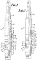
- a lock mandrel generally designated by reference numeral 10, is shown attached to the lower end of a running tool 12.
- the lock mandrel 10 is located in a tubing string (not shown) aligned with a landing nipple 14 shown in fragmentary cross-section.
- a no-go shoulder 16 of the lock mandrel 10 is seated against a corresponding no-go shoulder 18 of the landing nipple 14, and a core portion 20 of the running tool 12 extends into the interior of the lock mandrel 10.
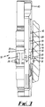
- the no-go shoulder 16 of the lock mandrel 10 is formed on an annular member 22 which surrounds a main body portion 24 of the mandrel 10 and is slidable along the longitudinal axis thereof between a first axial position, as seen in Figs. 1 and 2 and a second axial position as seen in Fig. 3.
- the lock mandrel 10 further includes a plurality of locking dogs 26 spaced around the circumference of the mandrel 10 and radially movable between a first, retracted position, as seen in Fig. 1, and a second extended position, as seen in Figs. 2 and 3, upon operation of the running tool 12 via a wireline toolstring (not shown).
- the dogs 26 extend through a corresponding plurality of longitudinally extending slots 28 formed in the annular member 22, and are aligned with an annular locking recess 30 of the landing nipple 14 when the respective no-go shoulders 16 and 18 are in contact.
- a second plurality of circumferentially spaced locking dogs 32 extend through a corresponding plurality of longitudinally extending slots 34 formed in the main body portion 24 of the mandrel 10 and are also radially movable between a first, extended position (Figs. 1 and 2) in which they engage a corresponding annular recess 36 formed on the inner surface of the annular member 22 so as to lock the annular member 22 in its first axial position, and a second, retracted position, in which the annular member 22 is free to move between its first and second axial positions.
- the second set of dogs 32 are maintained in their extended position by the core portion 20 of the running tool 12 extending into the interior of the lock mandrel 10.
- the running tool 12 and the lock mandrel 10, with an appropriate flow control device (not shown) attached thereto are lowered into the tubing string until the no-go shoulders 16 and 18 engage.
- a downward jar is applied to the core position of the running tool 12, which is transmitted to an inner sleeve portion 38 of the mandrel 10, via a fishing neck portion 40, shearing a first set of shear pins 42.
- the sleeve portion 38 moves downwards, moving the first plurality of locking dogs 26 into their extended position in which they project into the locking recess 30 of the landing nipple 14.
- a tell-tale device 44 on the running tool 12 confirms the proper operation of the assembly.
Landscapes
- Geology (AREA)
- Life Sciences & Earth Sciences (AREA)
- Engineering & Computer Science (AREA)
- Mining & Mineral Resources (AREA)
- Geochemistry & Mineralogy (AREA)
- Fluid Mechanics (AREA)
- Environmental & Geological Engineering (AREA)
- General Life Sciences & Earth Sciences (AREA)
- Physics & Mathematics (AREA)
- Earth Drilling (AREA)
- Preventing Unauthorised Actuation Of Valves (AREA)
- Quick-Acting Or Multi-Walled Pipe Joints (AREA)
- Fluid-Damping Devices (AREA)
- Orthopedics, Nursing, And Contraception (AREA)
- Replacement Of Web Rolls (AREA)
- Materials For Medical Uses (AREA)
Claims (7)
- Ein Verriegelungselement (10) zum Befestigen an einer Verriegelungsstruktur (14) in einer Rohrleitung, wobei die Verriegelungsstruktur (14) einen Verriegelungsstrukturvorsprung (18) und eine Verriegelungsvertiefung (30) aufweist, wobei das Verriegelungselement (10) ein Gehäuse (24) umfaßt; ein Verriegelungselementvorsprung (16), der angepaßt ist, um mit dem Verriegelungsstrukturvorsprung (18) einzukuppeln; eine Vertiefungsverriegelungsvorrichtung (26), die bewegbar an dem Gehäuse (24) befestigt ist, um sich zwischen einer ersten, eingezogenen Lage und einer zweiten, ausgestreckten Lage, in der die Vertiefungsverriegelungsvorrichtung (26) bei der Verriegelungsstruktur (14) in die Verriegelungsvertiefung (30) eintritt, zu bewegen; und dadurch gekennzeichnet, daß der Verriegelungselementvorsprung (16) bewegbar auf dem Gehäuse (24) zwischen einer ersten Lage, in der der Verriegelungselementvorsprung (16) bei Verwendung der Vorrichtung auf dem Verriegelungsstrukturvorsprung (18) und der Vertiefungsverriegelungsvorrichtung (26) lastet, wenn er in der ausgestreckten Lage von den Oberflächen der Verriegelungsvertiefung (30) der Verriegelungsstruktur (14) entkuppelt ist, und einer zweiten Lage, in der bei Verwendung der Vorrichtung die Vertiefungsverriegelungsvorrichtung (26) auf einer Oberfläche der Verriegelungsvertiefung (30) lastet, um mindestens einen Teil jeder auf ein Ende des Verriegelungselements (10) angewandeten Last zu stützen, lastet; und eine Vorsprungsverriegelungsvorrichtung (32) verriegelt wahlweise den Verriegelungselementvorsprung (16) in der ersten Lage.
- Ein Verriegelungselement nach Anspruch 1, wobei der Verriegelungselementvorsprung (16) auf einem ringförmigen Element (22) gebildet wird, das in der Axialrichtung beweglich auf dem Gehäuse (10) befestigt ist.
- Ein Verriegelungselement nach Anspruch 1 oder 2, wonach eine Vertiefungsverriegelungsvorrichtung (26) einen Verriegelungshaken aufweist.
- Ein Verriegelungselement nach einem der vorhergehenden Ansprüche, wonach die Vorsprungsverriegelungsvorrichtung einen Verriegelungshaken (32) aufweist.
- Ein Verriegelungselement nach Anspruch 4, wobei der Verriegelungshaken (32) bei der Verwendung der Vorrichtung durch ein an dem Verriegelungselement (10) befestigtes Laufwerkzeug (12) in der ausgestreckten Lage gehalten wird, und bei Entkuppelung des Laufwerkzeugs (12) von dem Verriegelungselement (10) geht der Verriegelungshaken (32) auf die eingezogene Stellung über.
- Ein Verriegelungselement nach einem der vorhergehenden Ansprüche, wobei das Verriegelungselement ein Verriegelungsdorn (10) ist, und die Verriegelungsstruktur, auf der es befestigt ist, ist bei Verwendung der Vorrichtung ein Absatznippel (14).
- Ein Verriegelungselement nach einem der vorhergehenden Ansprüche, wobei das Verriegelungselement (10) für den Einsatz in einem Bohrloch oder Schacht gedacht ist.
Applications Claiming Priority (2)
| Application Number | Priority Date | Filing Date | Title |
|---|---|---|---|
| GB9212162 | 1992-06-09 | ||
| GB929212162A GB9212162D0 (en) | 1992-06-09 | 1992-06-09 | Lock mandrel |
Publications (2)
| Publication Number | Publication Date |
|---|---|
| EP0574246A1 EP0574246A1 (de) | 1993-12-15 |
| EP0574246B1 true EP0574246B1 (de) | 1997-08-27 |
Family
ID=10716757
Family Applications (1)
| Application Number | Title | Priority Date | Filing Date |
|---|---|---|---|
| EP93304477A Expired - Lifetime EP0574246B1 (de) | 1992-06-09 | 1993-06-09 | Verriegelungselement für Durchflusssteuerungswerkzeuge im Bohrloch |
Country Status (5)
| Country | Link |
|---|---|
| US (1) | US5379837A (de) |
| EP (1) | EP0574246B1 (de) |
| AT (1) | ATE157425T1 (de) |
| DE (1) | DE69313357D1 (de) |
| GB (1) | GB9212162D0 (de) |
Families Citing this family (4)
| Publication number | Priority date | Publication date | Assignee | Title |
|---|---|---|---|---|
| GB2292268B (en) * | 1994-08-13 | 1998-09-16 | B D Kendle Engineering Ltd | Electric line quick release connectors |
| AU3298699A (en) | 1998-02-18 | 1999-09-06 | Camco International, Inc. | Well lock with multiple shear planes |
| EP2449206A2 (de) | 2009-06-29 | 2012-05-09 | Halliburton Energy Services, Inc. | Laserbetrieb für ein bohrloch |
| US8474542B2 (en) * | 2010-07-15 | 2013-07-02 | Weatherford/Lamb, Inc. | Selective and non-selective lock mandrel assembly having upward biased inner sleeve |
Family Cites Families (15)
| Publication number | Priority date | Publication date | Assignee | Title |
|---|---|---|---|---|
| US3646996A (en) * | 1970-04-24 | 1972-03-07 | Otis Eng Co | Well tools |
| US3893717A (en) * | 1974-05-15 | 1975-07-08 | Putch Samuel W | Well casing hanger assembly |
| FR2332413A1 (fr) * | 1975-11-19 | 1977-06-17 | Flopetrol Ste Auxil Prod Petro | Dispositif d'ancrage pour appareil de puits et outil de pose de ce dispositif |
| US4121659A (en) * | 1977-09-12 | 1978-10-24 | Otis Engineering Corporation | Collar lock and seal assembly for well tools |
| US4254829A (en) * | 1979-09-24 | 1981-03-10 | Camco, Incorporated | Well locking device |
| US4488596A (en) * | 1981-05-01 | 1984-12-18 | Baker International Corporation | Locking apparatus for use in a subterranean well |
| US4506731A (en) * | 1983-03-31 | 1985-03-26 | Halliburton Company | Apparatus for placement and retrieval of downhole gauges |
| US4580630A (en) * | 1984-08-20 | 1986-04-08 | Vetco Offshore, Inc. | Mudline casing hanger assembly |
| US4595054A (en) * | 1985-05-20 | 1986-06-17 | Camco, Incorporated | Well lock having retractable no-go dogs |
| GB2207157B (en) * | 1987-07-07 | 1991-05-29 | Petroline Wireline Services | Downhole lock assembly |
| US4886115A (en) * | 1988-10-14 | 1989-12-12 | Eastern Oil Tools Pte Ltd. | Wireline safety mechanism for wireline tools |
| US4949786A (en) * | 1989-04-07 | 1990-08-21 | Vecto Gray Inc. | Emergency casing hanger |
| US5070942A (en) * | 1990-09-05 | 1991-12-10 | Cooper Industries, Inc. | Well tubing hanger sealing assembly |
| US5174376A (en) * | 1990-12-21 | 1992-12-29 | Fmc Corporation | Metal-to-metal annulus packoff for a subsea wellhead system |
| GB9118408D0 (en) * | 1991-08-28 | 1991-10-16 | Petroline Wireline Services | Lock mandrel for downhole assemblies |
-
1992
- 1992-06-09 GB GB929212162A patent/GB9212162D0/en active Pending
-
1993
- 1993-06-04 US US08/071,255 patent/US5379837A/en not_active Expired - Fee Related
- 1993-06-09 EP EP93304477A patent/EP0574246B1/de not_active Expired - Lifetime
- 1993-06-09 DE DE69313357T patent/DE69313357D1/de not_active Expired - Lifetime
- 1993-06-09 AT AT93304477T patent/ATE157425T1/de not_active IP Right Cessation
Also Published As
| Publication number | Publication date |
|---|---|
| ATE157425T1 (de) | 1997-09-15 |
| DE69313357D1 (de) | 1997-10-02 |
| GB9212162D0 (en) | 1992-07-22 |
| US5379837A (en) | 1995-01-10 |
| EP0574246A1 (de) | 1993-12-15 |
Similar Documents
| Publication | Publication Date | Title |
|---|---|---|
| US4614233A (en) | Mechanically actuated downhole locking sub | |
| US3507329A (en) | Locating and anchoring device for well tools | |
| US3856081A (en) | Locking devices | |
| CA2087673C (en) | Perforating type lockout tool | |
| US5409059A (en) | Lock mandrel for downhole assemblies | |
| CA1057652A (en) | Running tool for downhole apparatus | |
| US4295528A (en) | Selective lock with setting and retrieving tools | |
| US3863961A (en) | Latching device | |
| US6923256B2 (en) | Disconnect device | |
| US4558895A (en) | Pulling tool | |
| GB2199057A (en) | Well tool lock mandrel and handling tools therefor | |
| US4986362A (en) | Running tool for use with reeled tubing and method of operating same | |
| US4265306A (en) | Latch for well tools | |
| US4944345A (en) | Well device lock mandrel and running tool | |
| GB2270940A (en) | Casing hanger running tool | |
| US2901045A (en) | Locking means for well tools | |
| US4488596A (en) | Locking apparatus for use in a subterranean well | |
| US4290484A (en) | Seal receptacle assembly | |
| EP0574246B1 (de) | Verriegelungselement für Durchflusssteuerungswerkzeuge im Bohrloch | |
| GB2272033A (en) | Contingency tieback connector | |
| US4554972A (en) | Well tool locking device | |
| US4379488A (en) | Latch for well tool | |
| US4962813A (en) | Well tool locking system for staggered bore | |
| US7347269B2 (en) | Flow tube exercising tool | |
| US4418750A (en) | Well tool |
Legal Events
| Date | Code | Title | Description |
|---|---|---|---|
| PUAI | Public reference made under article 153(3) epc to a published international application that has entered the european phase |
Free format text: ORIGINAL CODE: 0009012 |
|
| AK | Designated contracting states |
Kind code of ref document: A1 Designated state(s): AT BE CH DE DK ES FR GB GR IT LI LU NL SE |
|
| 17P | Request for examination filed |
Effective date: 19940513 |
|
| RAP1 | Party data changed (applicant data changed or rights of an application transferred) |
Owner name: WELL-EQUIP LIMITED |
|
| 17Q | First examination report despatched |
Effective date: 19960306 |
|
| GRAG | Despatch of communication of intention to grant |
Free format text: ORIGINAL CODE: EPIDOS AGRA |
|
| GRAH | Despatch of communication of intention to grant a patent |
Free format text: ORIGINAL CODE: EPIDOS IGRA |
|
| GRAH | Despatch of communication of intention to grant a patent |
Free format text: ORIGINAL CODE: EPIDOS IGRA |
|
| GRAA | (expected) grant |
Free format text: ORIGINAL CODE: 0009210 |
|
| AK | Designated contracting states |
Kind code of ref document: B1 Designated state(s): AT BE CH DE DK ES FR GB GR IT LI LU NL SE |
|
| PG25 | Lapsed in a contracting state [announced via postgrant information from national office to epo] |
Ref country code: NL Free format text: LAPSE BECAUSE OF FAILURE TO SUBMIT A TRANSLATION OF THE DESCRIPTION OR TO PAY THE FEE WITHIN THE PRESCRIBED TIME-LIMIT Effective date: 19970827 Ref country code: LI Free format text: LAPSE BECAUSE OF FAILURE TO SUBMIT A TRANSLATION OF THE DESCRIPTION OR TO PAY THE FEE WITHIN THE PRESCRIBED TIME-LIMIT Effective date: 19970827 Ref country code: GR Free format text: LAPSE BECAUSE OF FAILURE TO SUBMIT A TRANSLATION OF THE DESCRIPTION OR TO PAY THE FEE WITHIN THE PRESCRIBED TIME-LIMIT Effective date: 19970827 Ref country code: ES Free format text: THE PATENT HAS BEEN ANNULLED BY A DECISION OF A NATIONAL AUTHORITY Effective date: 19970827 Ref country code: DK Free format text: LAPSE BECAUSE OF NON-PAYMENT OF DUE FEES Effective date: 19970827 Ref country code: CH Free format text: LAPSE BECAUSE OF FAILURE TO SUBMIT A TRANSLATION OF THE DESCRIPTION OR TO PAY THE FEE WITHIN THE PRESCRIBED TIME-LIMIT Effective date: 19970827 Ref country code: BE Effective date: 19970827 Ref country code: AT Effective date: 19970827 |
|
| REF | Corresponds to: |
Ref document number: 157425 Country of ref document: AT Date of ref document: 19970915 Kind code of ref document: T |
|
| REG | Reference to a national code |
Ref country code: CH Ref legal event code: EP |
|
| REF | Corresponds to: |
Ref document number: 69313357 Country of ref document: DE Date of ref document: 19971002 |
|
| ET | Fr: translation filed | ||
| ITF | It: translation for a ep patent filed | ||
| PG25 | Lapsed in a contracting state [announced via postgrant information from national office to epo] |
Ref country code: SE Effective date: 19971127 |
|
| PG25 | Lapsed in a contracting state [announced via postgrant information from national office to epo] |
Ref country code: DE Effective date: 19971128 |
|
| NLV1 | Nl: lapsed or annulled due to failure to fulfill the requirements of art. 29p and 29m of the patents act | ||
| REG | Reference to a national code |
Ref country code: CH Ref legal event code: PL |
|
| PG25 | Lapsed in a contracting state [announced via postgrant information from national office to epo] |
Ref country code: LU Free format text: LAPSE BECAUSE OF NON-PAYMENT OF DUE FEES Effective date: 19980609 |
|
| PLBE | No opposition filed within time limit |
Free format text: ORIGINAL CODE: 0009261 |
|
| STAA | Information on the status of an ep patent application or granted ep patent |
Free format text: STATUS: NO OPPOSITION FILED WITHIN TIME LIMIT |
|
| 26N | No opposition filed | ||
| REG | Reference to a national code |
Ref country code: GB Ref legal event code: IF02 |
|
| PGFP | Annual fee paid to national office [announced via postgrant information from national office to epo] |
Ref country code: GB Payment date: 20020605 Year of fee payment: 10 |
|
| PGFP | Annual fee paid to national office [announced via postgrant information from national office to epo] |
Ref country code: FR Payment date: 20020610 Year of fee payment: 10 |
|
| PG25 | Lapsed in a contracting state [announced via postgrant information from national office to epo] |
Ref country code: GB Free format text: LAPSE BECAUSE OF NON-PAYMENT OF DUE FEES Effective date: 20030609 |
|
| GBPC | Gb: european patent ceased through non-payment of renewal fee |
Effective date: 20030609 |
|
| PG25 | Lapsed in a contracting state [announced via postgrant information from national office to epo] |
Ref country code: FR Free format text: LAPSE BECAUSE OF NON-PAYMENT OF DUE FEES Effective date: 20040227 |
|
| REG | Reference to a national code |
Ref country code: FR Ref legal event code: ST |
|
| PG25 | Lapsed in a contracting state [announced via postgrant information from national office to epo] |
Ref country code: IT Free format text: LAPSE BECAUSE OF NON-PAYMENT OF DUE FEES;WARNING: LAPSES OF ITALIAN PATENTS WITH EFFECTIVE DATE BEFORE 2007 MAY HAVE OCCURRED AT ANY TIME BEFORE 2007. THE CORRECT EFFECTIVE DATE MAY BE DIFFERENT FROM THE ONE RECORDED. Effective date: 20050609 |