EP0574171A1 - Partial oxidation of scrap rubber tires and used motor oil - Google Patents
Partial oxidation of scrap rubber tires and used motor oil Download PDFInfo
- Publication number
- EP0574171A1 EP0574171A1 EP93304195A EP93304195A EP0574171A1 EP 0574171 A1 EP0574171 A1 EP 0574171A1 EP 93304195 A EP93304195 A EP 93304195A EP 93304195 A EP93304195 A EP 93304195A EP 0574171 A1 EP0574171 A1 EP 0574171A1
- Authority
- EP
- European Patent Office
- Prior art keywords
- gas
- oil
- rubber
- process according
- hydrocarbonaceous liquid
- Prior art date
- Legal status (The legal status is an assumption and is not a legal conclusion. Google has not performed a legal analysis and makes no representation as to the accuracy of the status listed.)
- Granted
Links
Images
Classifications
-
- C—CHEMISTRY; METALLURGY
- C10—PETROLEUM, GAS OR COKE INDUSTRIES; TECHNICAL GASES CONTAINING CARBON MONOXIDE; FUELS; LUBRICANTS; PEAT
- C10J—PRODUCTION OF PRODUCER GAS, WATER-GAS, SYNTHESIS GAS FROM SOLID CARBONACEOUS MATERIAL, OR MIXTURES CONTAINING THESE GASES; CARBURETTING AIR OR OTHER GASES
- C10J3/00—Production of combustible gases containing carbon monoxide from solid carbonaceous fuels
- C10J3/46—Gasification of granular or pulverulent flues in suspension
- C10J3/48—Apparatus; Plants
- C10J3/485—Entrained flow gasifiers
-
- C—CHEMISTRY; METALLURGY
- C10—PETROLEUM, GAS OR COKE INDUSTRIES; TECHNICAL GASES CONTAINING CARBON MONOXIDE; FUELS; LUBRICANTS; PEAT
- C10J—PRODUCTION OF PRODUCER GAS, WATER-GAS, SYNTHESIS GAS FROM SOLID CARBONACEOUS MATERIAL, OR MIXTURES CONTAINING THESE GASES; CARBURETTING AIR OR OTHER GASES
- C10J3/00—Production of combustible gases containing carbon monoxide from solid carbonaceous fuels
- C10J3/72—Other features
- C10J3/82—Gas withdrawal means
- C10J3/84—Gas withdrawal means with means for removing dust or tar from the gas
-
- C—CHEMISTRY; METALLURGY
- C10—PETROLEUM, GAS OR COKE INDUSTRIES; TECHNICAL GASES CONTAINING CARBON MONOXIDE; FUELS; LUBRICANTS; PEAT
- C10J—PRODUCTION OF PRODUCER GAS, WATER-GAS, SYNTHESIS GAS FROM SOLID CARBONACEOUS MATERIAL, OR MIXTURES CONTAINING THESE GASES; CARBURETTING AIR OR OTHER GASES
- C10J3/00—Production of combustible gases containing carbon monoxide from solid carbonaceous fuels
- C10J3/72—Other features
- C10J3/86—Other features combined with waste-heat boilers
-
- C—CHEMISTRY; METALLURGY
- C10—PETROLEUM, GAS OR COKE INDUSTRIES; TECHNICAL GASES CONTAINING CARBON MONOXIDE; FUELS; LUBRICANTS; PEAT
- C10K—PURIFYING OR MODIFYING THE CHEMICAL COMPOSITION OF COMBUSTIBLE GASES CONTAINING CARBON MONOXIDE
- C10K1/00—Purifying combustible gases containing carbon monoxide
- C10K1/08—Purifying combustible gases containing carbon monoxide by washing with liquids; Reviving the used wash liquors
- C10K1/10—Purifying combustible gases containing carbon monoxide by washing with liquids; Reviving the used wash liquors with aqueous liquids
- C10K1/101—Purifying combustible gases containing carbon monoxide by washing with liquids; Reviving the used wash liquors with aqueous liquids with water only
-
- C—CHEMISTRY; METALLURGY
- C10—PETROLEUM, GAS OR COKE INDUSTRIES; TECHNICAL GASES CONTAINING CARBON MONOXIDE; FUELS; LUBRICANTS; PEAT
- C10J—PRODUCTION OF PRODUCER GAS, WATER-GAS, SYNTHESIS GAS FROM SOLID CARBONACEOUS MATERIAL, OR MIXTURES CONTAINING THESE GASES; CARBURETTING AIR OR OTHER GASES
- C10J2300/00—Details of gasification processes
- C10J2300/09—Details of the feed, e.g. feeding of spent catalyst, inert gas or halogens
- C10J2300/0903—Feed preparation
- C10J2300/0906—Physical processes, e.g. shredding, comminuting, chopping, sorting
-
- C—CHEMISTRY; METALLURGY
- C10—PETROLEUM, GAS OR COKE INDUSTRIES; TECHNICAL GASES CONTAINING CARBON MONOXIDE; FUELS; LUBRICANTS; PEAT
- C10J—PRODUCTION OF PRODUCER GAS, WATER-GAS, SYNTHESIS GAS FROM SOLID CARBONACEOUS MATERIAL, OR MIXTURES CONTAINING THESE GASES; CARBURETTING AIR OR OTHER GASES
- C10J2300/00—Details of gasification processes
- C10J2300/16—Integration of gasification processes with another plant or parts within the plant
- C10J2300/1687—Integration of gasification processes with another plant or parts within the plant with steam generation
-
- C—CHEMISTRY; METALLURGY
- C10—PETROLEUM, GAS OR COKE INDUSTRIES; TECHNICAL GASES CONTAINING CARBON MONOXIDE; FUELS; LUBRICANTS; PEAT
- C10J—PRODUCTION OF PRODUCER GAS, WATER-GAS, SYNTHESIS GAS FROM SOLID CARBONACEOUS MATERIAL, OR MIXTURES CONTAINING THESE GASES; CARBURETTING AIR OR OTHER GASES
- C10J2300/00—Details of gasification processes
- C10J2300/18—Details of the gasification process, e.g. loops, autothermal operation
- C10J2300/1846—Partial oxidation, i.e. injection of air or oxygen only
-
- C—CHEMISTRY; METALLURGY
- C10—PETROLEUM, GAS OR COKE INDUSTRIES; TECHNICAL GASES CONTAINING CARBON MONOXIDE; FUELS; LUBRICANTS; PEAT
- C10J—PRODUCTION OF PRODUCER GAS, WATER-GAS, SYNTHESIS GAS FROM SOLID CARBONACEOUS MATERIAL, OR MIXTURES CONTAINING THESE GASES; CARBURETTING AIR OR OTHER GASES
- C10J2300/00—Details of gasification processes
- C10J2300/18—Details of the gasification process, e.g. loops, autothermal operation
- C10J2300/1861—Heat exchange between at least two process streams
- C10J2300/1884—Heat exchange between at least two process streams with one stream being synthesis gas
-
- C—CHEMISTRY; METALLURGY
- C10—PETROLEUM, GAS OR COKE INDUSTRIES; TECHNICAL GASES CONTAINING CARBON MONOXIDE; FUELS; LUBRICANTS; PEAT
- C10J—PRODUCTION OF PRODUCER GAS, WATER-GAS, SYNTHESIS GAS FROM SOLID CARBONACEOUS MATERIAL, OR MIXTURES CONTAINING THESE GASES; CARBURETTING AIR OR OTHER GASES
- C10J2300/00—Details of gasification processes
- C10J2300/18—Details of the gasification process, e.g. loops, autothermal operation
- C10J2300/1861—Heat exchange between at least two process streams
- C10J2300/1892—Heat exchange between at least two process streams with one stream being water/steam
-
- Y—GENERAL TAGGING OF NEW TECHNOLOGICAL DEVELOPMENTS; GENERAL TAGGING OF CROSS-SECTIONAL TECHNOLOGIES SPANNING OVER SEVERAL SECTIONS OF THE IPC; TECHNICAL SUBJECTS COVERED BY FORMER USPC CROSS-REFERENCE ART COLLECTIONS [XRACs] AND DIGESTS
- Y02—TECHNOLOGIES OR APPLICATIONS FOR MITIGATION OR ADAPTATION AGAINST CLIMATE CHANGE
- Y02P—CLIMATE CHANGE MITIGATION TECHNOLOGIES IN THE PRODUCTION OR PROCESSING OF GOODS
- Y02P20/00—Technologies relating to chemical industry
- Y02P20/141—Feedstock
- Y02P20/143—Feedstock the feedstock being recycled material, e.g. plastics
Definitions
- This invention relates to the processing of rubber, oil soluble plastics, and rubber-containing materials, such as used automobile and truck tires into a pumpable liquid hydrocarbonaceous feed to a partial oxidation gas generator for the production of raw synthesis gas, reducing gas, or fuel gas.
- This invention pertains to the partial oxidation of scrap rubber tires comprising the steps of:
- Scrap rubber tires for example from automobiles, trucks, and buses, as well as waste lubricating oil are disposed of by the process of the subject invention without polluting the nation's environment. Further, useful product synthesis gas, reducing gas, fuel gas, and light fuel oil is produced.
- Scrap rubber tires from automobiles, trucks and buses and other rubber-containing materials, oil soluble plastics and waste hydrocarbonaceous oils such as used motor oil are the feedstocks to the subject process.
- Substantially any form of vulcanized or un-vulcanized scrap or waste natural or synthetic rubber that will dissolve in a liquid hydrocarbon may be used.
- Synthetic rubber includes, for example, butadiene, isoprene, chloroprene and copolymers with styrene, alpha methyl styrene, divinyl benzene, ethylene, propylene, isobutylene, ethylenically unsaturated carboxylic acid, ester or nitrile, and others.
- Rubber chemicals and compounding ingredients may be included in the rubber, such as pigments, softeners, vulcanizing and curing agents, anti-ozonants, and anti-oxidants.
- Reinforcing belts made from metal, fiberglass, or organic fibers, and beads made from metal wire are usually molded into the rubber tires. There separation and removal from the rubber tires are relatively inexpensive by the subject process.
- Oil soluble plastics include, polyamides (nylon), polyesters (polyethyleneterephthate), polystyrene, cellulose acetate, polypropylene, and other thermoplastics dissolve in the liquid hydrocarbonaceous solvent along with the rubber. Rayon, fiberglass, and metal mesh materials will not dissolve in the liquid hydrocarbonaceous solvent. Rather, they are separated from the tire-oil by filtration or centrifuge.
- the size of the rubber tires is preferably reduced to less than about 15cm x 5cm x 5cm (6'' x 2'' x 2'') by means of commercially available cutting and shredding equipment.
- the liquid hydrocarbonaceous solvent includes petroleum oils. Oils having the following properties are suitable: initial atmospheric boiling point, less than 288°C (550°F), Neutralization No., mg KOH/g. 0.70 to 1.0, Aniline point 38°C to 43°C (100°F to 110°F). Used hydrocarbon automobile motor oil is the preferable hydrocarbon solvent. Coal-tar derived hydrocarbon oils may be used. Other, suitable oils comply with ASTM Specification D2226, Types 101 and 102.
- the liquefaction reaction vessel is charged with a pumpable liquid hydrocarbonaceous liquid solvent, such as used motor oil, at a temperature in the range of about 93°C to 149°C (200°F to 300°F).
- a pumpable liquid hydrocarbonaceous liquid solvent such as used motor oil
- the pieces of rubber, rubber-containing material, oil-soluble plastics and mixtures thereof, such as whole or small pieces of automobile or truck tires are introduced into the reaction vessel.
- a small stream of the oil solvent is continuously removed from the bottom of the reaction vessel and pumped through an oil heater.
- the heated oil solvent is then returned to the liquefaction reaction vessel. Recirculation and reheating of the oil is continued for about 15 to 90 minutes until a maximum temperature in the range of about 260°C to 454°C (500°F to 850°F) is reached. Each time that the oil solvent is recirculated through the oil heater, the temperature of the oil is increased an additional 28°C to 139°C (50°F to 250°F). That is, the temperature of the oil leaving the oil heater is about 28°C to 139°C (50°F to 250°F) greater than the oil entering the oil heater.
- the circulating oil continues to contact the rubber, rubber-containing material, oil soluble plastics and mixtures thereof until 90 to 100 wt.% of the materials dissolve in the pumpable circulating oil. For example, this will usually take an additional 15 to 90 minutes after the oil solvent reaches maximum temperature.
- the subject liquefaction reactor with circulating hot oil solvent provides good heat transfer, minimum degradation and/or cracking of the oil solvent, in transit mixing and high solubility of the rubber, rubber-containing materials, and oil-soluble plastics.
- the pressure in the liquefaction reactor is in the range of about 1 to 20 atmospheres.
- the reaction takes place in the absence of oxygen.
- the gaseous materials leaving through the overhead vent line in the reactor vessel are cooled below the dew point and condensed.
- Liquids are produced, including gasoline, diesel oil, and light fuel oil, and are separated from non-condensible vapors in a knock out pot. From about 0 to 100 wt.%, such as about 25 to 75 wt.% of the condensate may be used as solvent.
- this solvent is used to wash off undissolved rubber and sticky oil from metal belts and other non oil-soluble materials that are separated from a homogeneous pumpable heavy hydrocarbonaceous liquid that is produced in said liquefaction reactor.
- This hydrocarbonaceous liquid is also referred to herein as tire-oil. It contains about 20 to 80 weight percent of dissolved rubber and/or oil soluble plastics.
- the remainder of the condensate is sent to a mix tank prior to introduction into a conventional partial oxidation gas generator.
- the overhead from said knock out pot comprises non-condensed C4, C5 or less hydrocarbons with trace amounts of H2S and mercaptans.
- Butenes result from the break-up of styrene butadiene rubber polymer which is the main constituent of tire rubber.
- These non-condensible gaseous materials may be used as a gaseous fuel for heating the used motor oil solvent or introduced directly into the partial oxidation gas generator.
- Undissolved tire belt material selected from the group consisting of steel mesh, fiberglass, rayon, and mixtures thereof and containing about 1 to 10 wt.% of undissolved rubber and/or oily materials, along with solid residue comprising dirt, zinc oxide accelerator, and zinc sulfide pass directly into a coking reactor; and alternatively passes into a solvent wash step prior to entering the coking reactor.
- the expression A and/or B is used herein in its common form and means either A or B or mixtures of A and B.
- an oxygen-free atmosphere in the coking reactor at a temperature in the range of about 260°C to 816°C (500°F to 1500°F) for about 30 to 90 minutes at atmospheric pressure the aforesaid undissolved tire belt materials are converted into a gas and dry products.
- the dry products comprise carbon black, metal, and other inorganic substances in tires such as fiberglass.
- the composition of the gases which evolve during the coking reaction are similar to that of the off-gas from the liquefaction reactor.
- the off-gas from the coking reactor is mixed with the off-gas from the liquefaction reactor and processed in the manner described previously.
- Carbon black powder is separated from inorganic materials e.g. metal and fiberglass by means of a conventional magnetic separator, vibrating screen, air classifier, and combinations thereof and introduced into a mixing tank for preparing a feed to the partial oxidation gas generator.
- the fiberglass is cut, sheared and mixed with the carbon black going into said mixing tank.
- dried or pressed municipal sewage sludge and/or other burnable waste material is introduced into the mixing tank along with said other materials for preparation of a slurry feed to the partial oxidation gas generator.
- a suitable partial oxidation gas generator is shown and described in coassigned U.S. Patent No. 3,544,291, which is incorporated hereby by reference.
- a three or four stream annular type burner such as shown and described in coassigned U.S. Patent Nos. 3,847,564 and 4,525,175, which are incorporated herein by reference, may be used to introduce the feedstreams into the partial oxidation gas generator.
- the burner assembly is inserted downward through a top inlet port of the noncatalytic synthesis gas generator.
- the burner extends along the central longitudinal axis of the gas generator with the downstream end discharging a multiphase mixture of fuel, free-oxygen containing gas, and temperature moderator directly into the reaction zone.
- the relative proportions of the feedstreams to the gas generator are carefully regulated to convert a substantial portion of the carbon in the fuel e.g., up to about 90% or more by weight, to carbon oxides; and to maintain an autogenous reaction zone temperature in the range of about 982°C to 1927°C (1800°F to 3500°F).
- the temperature in the gasifier is in the range of about 2200°F to 2800°F.
- the weight ratio of H2O to carbon in the feed is in the range of about 0.2 to 3.0, such as about 1.0 to 2.0.
- the atomic ratio of free-oxygen to carbon in the feed is in the range of about 0.8 to 1.4, such as about 1.0 to 1.2.
- the high amount of combined oxygen in the sewage sludge reduces the amount of free-oxygen.
- the dwell time in the reaction zone is in the range of about 1 to 10 seconds, and preferably in the range of about 2 to 8 seconds.
- the composition of the effluent gas from the gas generator in mole % dry basis may be as follows: H2 10 to 60, CO 20 to 60, CO2 5 to 40, CH4 0.01 to 5, H2S + COS 0.01 to 5, N2 nil to 5, and Ar nil to 1.5.
- the composition of the generator effluent gas in moe % dry basis may be about as follows: H2 2 to 20, CO 5 to 35, CO2 5 to 25, CH4 0 to 2, H2S + COS 0 to 3, N2 45 to 80, and Ar 0.5 to 1.5.
- Unconverted carbon ash, or molten slag are contained in the effluent gas stream.
- the effluent gas stream is called synthesis gas, reducing gas, or fuel gas.
- the hot gaseous effluent stream from the reaction zone of the synthesis gas generator is quickly cooled below the reaction temperature to a temperature in the range of about 121°C to 371°C (250°F to 700°F) by direct quenching in water, or by indirect heat exchange for example with water to produce steam in gas cooler.
- the gas stream may be cleaned and purified by conventional methods. For example, reference is made to coassigned U.S. Patent No. 4,052,176, which is included herein by reference for removal of H2S, COS, and CO2.
- a portion of the synthesis gas product at a temperature in the range of about 204°C to 816°C (400°F to 1500°F) is introduced into the coking reactor as a carrier gas and to accelerate the coking reaction.
- About 0.5 to 1.5 lbs, say 1.0 lb of syngas may be used to process each lb of residual tire belt material.
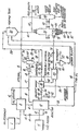
- Used motor oil in oil storage tank 1 is passed through line 2 into oil heater 3 where it is heated by indirect heat exchange with steam from line 4 and/or by an oil or gas fired heater. Flue gas from the oil heaters pass through line 5.
- Oil at a temperature in the range of about 93°C to 149°C (200°F to 300°F) is passed through line 6 into closed liquefaction reactor 10.
- Pieces of rubber tires about 15cm x 5cm x 5cm (6'' x 2'' x 2'') in storage hopper 11 are passed through line 12 into reactor 10. There they are contacted by said hot oil and are heated.
- the hot process oil is continuously recirculated between oil heater 3 and liquefaction reactor 10 by way of line 13, valve 14 and line 15 to oil heater 3 where the oil is heated by indirect heat exchange with steam, or by burning oil or gas and then through line 6.
- the temperature of the process oil is increased about 28°C to 139°C (50°F to 250°F).
- the temperature of the oil is thereby gradually brought up to a maximum temperature in the range of about 260°C to 454°C (500°F to 850°F).
- the recirculation of the oil is continued at the maximum temperature until at least 90 wt.% of the rubber and/or oil soluble plastic is dissolved in the oil and a pumpable homogeneous tire-oil is produced.
- the evolved gases are passed through vent line 16 and mixed in line 17 with the vented flue gas from line 5.
- the mixture of gases in line 18 are cooled to the dew point in cooler 19.
- the mixture of condensate and non-condensible gases in line 20 are separated in knock out pot 21.
- Non-condensible gases in line 22 at the top of knock out pot 21 may be treated to remove H2S and either utilized elsewhere in the process to provide process heat, injected into partial oxidation gasifier 25 as a portion of the feed, or flared.
- From about 0 to 100 wt.% of the condensate leaving through line 26 at the bottom of knock out pot 21 may be passed through line 27, valve 28, and line 29 into mixing tank 30. The remainder is introduced into solvent wash 38. In one embodiment from about 10 to 100 wt.% of the condensate in line 26 is passed through line 35, valve 36, line 37 into solvent wash zone 38. The remainder is introduced into mixing tank 30.
- the homogeneous tire oil produced in reactor 10 is passed through screening means (not shown) near the bottom of reactor 10 and is then passed through lines 45 and 46 into mixing tank 30.
- An oily solids stream comprising belting material such as metal and fiberglass as well as residual rubber material and adhered tire oil which is separated from the tire oil by said screening means leaves reactor 10 through line 47. With valve 48 in line 49 closed, the oily solids is passed through line 50, open valve 51, line 52, and into coking reactor 53.
- Organic vapors are produced in coking reactor 53 and leave through vent line 54. They are mixed in line 18 with the mixture of organic vapors from line 17 and are processed in the manner described previously.
- the dry materials leaving coking reactor 53 through line 55 are passed into a conventional separating means 56.
- Conventional vibrating screens, magnetic separators, or air classifiers may be used for separating means 56.
- the inorganic materials e.g. metal belts, fiberglass leave separating means 56 through line 57, and the carbon black leaves through line 58.
- the oily belt materials from liquefaction reactor 10 is passed through lines 47, 49, valve 48 and line 44 into solvent wash zone 38.
- the oily belts may be cleaned by a portion of the condensate solvent from line 37.
- steam from waste heat boiler 69 may be used to clean the oily belts.
- the recovered condensate solvent in line 59 is mixed in line 46 with the tire-oil from line 45 and introduced into mixing tank 30.
- the washed metal belt material in line 60 in introduced into coking reactor 53 for further cleaning.
- the tire-oil, with or without admixture with recovered solvent in line 46, is introduced into mix tank 30 along with carbon black and with or without crushed fiberglass from line 58 and with or without condensate from line 29.
- the mixture of materials is passed through line 61 and an intermediate passage of an annular type burner (not shown) into a conventional partial oxidation gas generator 25.
- Free-oxygen containing gas, optionally in admixture with a temperature moderator e.g. steam, in line 62 passes through the- central and outer passages of said burner.
- the partial oxidation reaction takes place in the refractory lined reaction zone in gas generator 25.
- the raw synthesis or fuel gas is split so that a portion e.g. about 25 to 75 mole % of the raw synthesis or fuel gas stream with entrained slag passes down through dip tube 63 and into quench water 64. Slag separates from the gas stream and leaves through line 65, valve 66, and line 67. The remainder of the raw synthesis or fuel gas is passed through side outlet 68 into waste heat boiler 69. Boiler feed water in line 70 is converted into steam by indirect heat exchange with the raw synthesis gas in waste heat boiler 69. The steam is then passed through line 4 and introduced into a heat exchanger in 3 to heat the used motor oil feed, as previously described. The partially cooled raw synthesis or fuel gas leaves through line 71. After purification to remove acid gases e.g. H2S, COS and CO2, the synthesis gas is used for chemical synthesis. Depending upon its composition e.g. high methane contact in addition to H2 + CO, the gas stream may be used as fuel gas, for example as the fuel in oil heater 3.
- the quenched portion of raw synthesis gas is passed through side outlet 75, line 76, valve 77, and line 78 into coking reactor 53 where it helps to maintain a reducing atmosphere, aids the coking reaction, and sweeps the gaseous products from the coking reaction through vent line 54.
- 22.5 kg (49.5 lbs) of used motor oil at a temperature of 121°C (250°F) are introduced into a liquefaction reactor filled with tire oil and containing 22.6 kg (50 lbs) of pieces of rubber tires.
- 22.5 kg (49.5 lbs) of used motor oil are removed from the reactor and recirculated to an oil heater where its temperature is increased about 56°C to 167°C (100°F to 300°F).
- the heated tire oil is then reintroduced into the liquefaction reactor where it directly contacts the tire pieces. Recirculation of the motor oil between the reactor and the oil heater is continued until the motor oil reaches a temperature of about 750°F, and then for an additional hour at 399°C (750°F).
- the following materials derived from the process are mixed together and introduced into the reaction zone of a partial oxidation gas generator for the production of syngas. There they are reacted with a free-oxygen containing gas e.g. air in admixture with H2O to produce synthesis gas: tire oil - 29.5 kg (65 lbs), carbon black - 2.3 kg (5 lbs), and condensate derived from the overhead from the liquefaction and coking reactors - 10 kg (22.5 lbs).
- a free-oxygen containing gas e.g. air in admixture with H2O to produce synthesis gas: tire oil - 29.5 kg (65 lbs), carbon black - 2.3 kg (5 lbs), and condensate derived from the overhead from the liquefaction and coking reactors - 10 kg (22.5 lbs).
- the hot raw synthesis gas is passed through a waste heat boiler to produce steam. A portion of the steam is used to heat up the used motor oil solvent.
Abstract
Description
- This invention relates to the processing of rubber, oil soluble plastics, and rubber-containing materials, such as used automobile and truck tires into a pumpable liquid hydrocarbonaceous feed to a partial oxidation gas generator for the production of raw synthesis gas, reducing gas, or fuel gas.
- The disposal of used rubber automobile and truck tires brings about difficult environmental problems that face all industrialized countries. This nation's pile of discarded tires has been estimated to be over three billion. Over about 200 million waste tires are generated annually in the United States.
- In contrast with the subject invention, the processes described in U.S. Patent No. 4,384,151 and 4,983,278 do not feed a liquid tire-oil fuel to a partial oxidation gas generator for the production of a gaseous mixture comprising H₂ + CO. A slurry feed to a gasifier comprising a suspension of small pieces of rubber is mentioned in coassigned U.S. Patent No. 4,371,378. However, such a material is significantly different from the subject invention wherein a homogeneous liquid tire-oil feed made by dissolving the rubber from rubber automobile or truck tires in a used motor oil solvent, in admixture with a light condensate oil and carbon black are fed to a partial oxidation gas generator.
- This invention pertains to the partial oxidation of scrap rubber tires comprising the steps of:
- (1) contacting a feed material selected from the group consisting of rubber, rubber-containing material, oil soluble plastics, and mixtures thereof with a pumpable hydrocarbonaceous liquid in a vented liquefaction reaction vessel in which the pressure is in the range of about 1 to 20.3 bars (1 to 20 atmospheres); gradually increasing the temperature of said hydrocarbonaceous liquid from about 93°C (200°F) to a maximum temperature in the range of about 260°C to 454°C (500°F to 850°F), and contacting said feed material with said pumpable hydrocarbonaceous liquid at said maximum temperature until more than about 90 wt.% of the rubber and/or oil soluble plastic feed material has been dissolved in said hydrocarbonaceous liquid, wherein the following materials (a) to (d) are produced:
- (a) a pumpable heavy hydrocarbonaceous liquid containing about 20 to 80 weight percent of dissolved rubber and/or oil-soluble plastics;
- (b) undissolved tire belt material selected from the group consisting of steel mesh, fiberglass, rayon, and mixtures thereof containing less than 10.0 wt.% of undissolved rubber and/or oily materials;
- (c) solid residue; and
- (d) off gas comprising light hydrocarbons having a maximum atmospheric boiling point of 454°C (850°F), and H₂S;
- (2) introducing materials (1) (b) into a closed vented coking zone maintained at a temperature in the range of about 260°C to 816°C (500°F to 1500°F) and a pressure in the range of about 1 to 20.3 bars (1 to 20 atmospheres) in the absence of oxygen, and producing and separating the following materials:
- (a) off gas comprising light hydrocarbons having a maximum atmospheric boiling point of 454°C (850°F),
- (b) inorganic materials, and (c) carbon black;
- (3) mixing off-gas (1)(d) from said reaction vessel in (1), and off gas (2)(a) from said coking zone in (2); and cooling said off-gas mixture to produce a liquid condensate and a separate stream of non-condensible fuel gas comprising C₁-C₅ hydrocarbons; and
- (4) introducing said pumpable heavy hydrocarbonaceous liquid from (1)(a) into the reaction zone of a partial oxidation gas generator along with at least a portion of said liquid condensate from (3) and said carbon black from (2)(c) and a free-oxygen containing gas and a temperature moderator and reacting said materials by partial oxidation at a temperature in the range of about 1 to 300 atmospheres, an atomic ratio of O/C in the range of about 0.8 to 1.5, and a weight ratio of H₂O to carbon in the range of about 0.2 to 3.0, thereby producing a hot raw effluent gas stream comprising H₂, CO, CO₂, H₂O, H₂S, and optionally N₂.
- The invention will be further understood by reference to the accompanying drawing which is a schematic representation of a preferred embodiment of a process according to the invention.
- Scrap rubber tires for example from automobiles, trucks, and buses, as well as waste lubricating oil are disposed of by the process of the subject invention without polluting the nation's environment. Further, useful product synthesis gas, reducing gas, fuel gas, and light fuel oil is produced.
- Scrap rubber tires from automobiles, trucks and buses and other rubber-containing materials, oil soluble plastics and waste hydrocarbonaceous oils such as used motor oil are the feedstocks to the subject process. Substantially any form of vulcanized or un-vulcanized scrap or waste natural or synthetic rubber that will dissolve in a liquid hydrocarbon may be used. Synthetic rubber includes, for example, butadiene, isoprene, chloroprene and copolymers with styrene, alpha methyl styrene, divinyl benzene, ethylene, propylene, isobutylene, ethylenically unsaturated carboxylic acid, ester or nitrile, and others. Conventional rubber chemicals and compounding ingredients may be included in the rubber, such as pigments, softeners, vulcanizing and curing agents, anti-ozonants, and anti-oxidants. Reinforcing belts made from metal, fiberglass, or organic fibers, and beads made from metal wire are usually molded into the rubber tires. There separation and removal from the rubber tires are relatively inexpensive by the subject process. Oil soluble plastics include, polyamides (nylon), polyesters (polyethyleneterephthate), polystyrene, cellulose acetate, polypropylene, and other thermoplastics dissolve in the liquid hydrocarbonaceous solvent along with the rubber. Rayon, fiberglass, and metal mesh materials will not dissolve in the liquid hydrocarbonaceous solvent. Rather, they are separated from the tire-oil by filtration or centrifuge.
- The size of the rubber tires is preferably reduced to less than about 15cm x 5cm x 5cm (6'' x 2'' x 2'') by means of commercially available cutting and shredding equipment.
- The liquid hydrocarbonaceous solvent includes petroleum oils. Oils having the following properties are suitable: initial atmospheric boiling point, less than 288°C (550°F), Neutralization No., mg KOH/g. 0.70 to 1.0, Aniline point 38°C to 43°C (100°F to 110°F). Used hydrocarbon automobile motor oil is the preferable hydrocarbon solvent. Coal-tar derived hydrocarbon oils may be used. Other, suitable oils comply with ASTM Specification D2226, Types 101 and 102.
- In the subject process, the liquefaction reaction vessel is charged with a pumpable liquid hydrocarbonaceous liquid solvent, such as used motor oil, at a temperature in the range of about 93°C to 149°C (200°F to 300°F). The pieces of rubber, rubber-containing material, oil-soluble plastics and mixtures thereof, such as whole or small pieces of automobile or truck tires are introduced into the reaction vessel. There are about 5 to 0.5 parts by wt. of oil solvent for each part by wt. of rubber, rubber-containing material, oil soluble plastics, or mixtures thereof. A small stream of the oil solvent is continuously removed from the bottom of the reaction vessel and pumped through an oil heater.
- The heated oil solvent is then returned to the liquefaction reaction vessel. Recirculation and reheating of the oil is continued for about 15 to 90 minutes until a maximum temperature in the range of about 260°C to 454°C (500°F to 850°F) is reached. Each time that the oil solvent is recirculated through the oil heater, the temperature of the oil is increased an additional 28°C to 139°C (50°F to 250°F). That is, the temperature of the oil leaving the oil heater is about 28°C to 139°C (50°F to 250°F) greater than the oil entering the oil heater. After the maximum temperature is reached, the circulating oil continues to contact the rubber, rubber-containing material, oil soluble plastics and mixtures thereof until 90 to 100 wt.% of the materials dissolve in the pumpable circulating oil. For example, this will usually take an additional 15 to 90 minutes after the oil solvent reaches maximum temperature.
- The subject liquefaction reactor with circulating hot oil solvent provides good heat transfer, minimum degradation and/or cracking of the oil solvent, in transit mixing and high solubility of the rubber, rubber-containing materials, and oil-soluble plastics. The pressure in the liquefaction reactor is in the range of about 1 to 20 atmospheres. The reaction takes place in the absence of oxygen. The gaseous materials leaving through the overhead vent line in the reactor vessel are cooled below the dew point and condensed. Liquids are produced, including gasoline, diesel oil, and light fuel oil, and are separated from non-condensible vapors in a knock out pot. From about 0 to 100 wt.%, such as about 25 to 75 wt.% of the condensate may be used as solvent. In one embodiment, this solvent is used to wash off undissolved rubber and sticky oil from metal belts and other non oil-soluble materials that are separated from a homogeneous pumpable heavy hydrocarbonaceous liquid that is produced in said liquefaction reactor. This hydrocarbonaceous liquid is also referred to herein as tire-oil. It contains about 20 to 80 weight percent of dissolved rubber and/or oil soluble plastics. The remainder of the condensate is sent to a mix tank prior to introduction into a conventional partial oxidation gas generator. The overhead from said knock out pot comprises non-condensed C₄, C₅ or less hydrocarbons with trace amounts of H₂S and mercaptans. Butenes result from the break-up of styrene butadiene rubber polymer which is the main constituent of tire rubber. These non-condensible gaseous materials may be used as a gaseous fuel for heating the used motor oil solvent or introduced directly into the partial oxidation gas generator.
- Undissolved tire belt material selected from the group consisting of steel mesh, fiberglass, rayon, and mixtures thereof and containing about 1 to 10 wt.% of undissolved rubber and/or oily materials, along with solid residue comprising dirt, zinc oxide accelerator, and zinc sulfide pass directly into a coking reactor; and alternatively passes into a solvent wash step prior to entering the coking reactor. The expression A and/or B is used herein in its common form and means either A or B or mixtures of A and B. In an oxygen-free atmosphere in the coking reactor at a temperature in the range of about 260°C to 816°C (500°F to 1500°F) for about 30 to 90 minutes at atmospheric pressure, the aforesaid undissolved tire belt materials are converted into a gas and dry products. The dry products comprise carbon black, metal, and other inorganic substances in tires such as fiberglass. The composition of the gases which evolve during the coking reaction are similar to that of the off-gas from the liquefaction reactor. In the preferred embodiment, the off-gas from the coking reactor is mixed with the off-gas from the liquefaction reactor and processed in the manner described previously. Carbon black powder is separated from inorganic materials e.g. metal and fiberglass by means of a conventional magnetic separator, vibrating screen, air classifier, and combinations thereof and introduced into a mixing tank for preparing a feed to the partial oxidation gas generator. In one embodiment, the fiberglass is cut, sheared and mixed with the carbon black going into said mixing tank. In another embodiment, dried or pressed municipal sewage sludge and/or other burnable waste material is introduced into the mixing tank along with said other materials for preparation of a slurry feed to the partial oxidation gas generator.
- A suitable partial oxidation gas generator is shown and described in coassigned U.S. Patent No. 3,544,291, which is incorporated hereby by reference. A three or four stream annular type burner, such as shown and described in coassigned U.S. Patent Nos. 3,847,564 and 4,525,175, which are incorporated herein by reference, may be used to introduce the feedstreams into the partial oxidation gas generator.
- The burner assembly is inserted downward through a top inlet port of the noncatalytic synthesis gas generator. The burner extends along the central longitudinal axis of the gas generator with the downstream end discharging a multiphase mixture of fuel, free-oxygen containing gas, and temperature moderator directly into the reaction zone.
- The relative proportions of the feedstreams to the gas generator are carefully regulated to convert a substantial portion of the carbon in the fuel e.g., up to about 90% or more by weight, to carbon oxides; and to maintain an autogenous reaction zone temperature in the range of about 982°C to 1927°C (1800°F to 3500°F). Preferably the temperature in the gasifier is in the range of about 2200°F to 2800°F. Further, the weight ratio of H₂O to carbon in the feed is in the range of about 0.2 to 3.0, such as about 1.0 to 2.0. The atomic ratio of free-oxygen to carbon in the feed is in the range of about 0.8 to 1.4, such as about 1.0 to 1.2. Advantageously, the high amount of combined oxygen in the sewage sludge reduces the amount of free-oxygen.
- The dwell time in the reaction zone is in the range of about 1 to 10 seconds, and preferably in the range of about 2 to 8 seconds. With substantially pure oxygen feed to the gas generator, the composition of the effluent gas from the gas generator in mole % dry basis may be as follows:
H₂ 10 to 60,CO 20 to 60, CO₂ 5 to 40, CH₄ 0.01 to 5, H₂S + COS 0.01 to 5, N₂ nil to 5, and Ar nil to 1.5. With air feed to the gas generator, the composition of the generator effluent gas in moe % dry basis may be about as follows: H₂ 2 to 20, CO 5 to 35, CO₂ 5 to 25, CH₄ 0 to 2, H₂S + COS 0 to 3,N₂ 45 to 80, and Ar 0.5 to 1.5. Unconverted carbon ash, or molten slag are contained in the effluent gas stream. Depending on the composition and use, the effluent gas stream is called synthesis gas, reducing gas, or fuel gas. - The hot gaseous effluent stream from the reaction zone of the synthesis gas generator is quickly cooled below the reaction temperature to a temperature in the range of about 121°C to 371°C (250°F to 700°F) by direct quenching in water, or by indirect heat exchange for example with water to produce steam in gas cooler. The gas stream may be cleaned and purified by conventional methods. For example, reference is made to coassigned U.S. Patent No. 4,052,176, which is included herein by reference for removal of H₂S, COS, and CO₂.
- In one embodiment, a portion of the synthesis gas product at a temperature in the range of about 204°C to 816°C (400°F to 1500°F) is introduced into the coking reactor as a carrier gas and to accelerate the coking reaction. About 0.5 to 1.5 lbs, say 1.0 lb of syngas may be used to process each lb of residual tire belt material.
- A more complete understanding of the invention may be had by reference to the accompanying drawing which illustrates a preferred embodiment of the invention. It is not intended to limit the subject invention to the particular process or materials described.
- Used motor oil in
oil storage tank 1 is passed through line 2 intooil heater 3 where it is heated by indirect heat exchange with steam from line 4 and/or by an oil or gas fired heater. Flue gas from the oil heaters pass through line 5. Oil at a temperature in the range of about 93°C to 149°C (200°F to 300°F) is passed through line 6 into closedliquefaction reactor 10. Pieces of rubber tires about 15cm x 5cm x 5cm (6'' x 2'' x 2'') instorage hopper 11 are passed throughline 12 intoreactor 10. There they are contacted by said hot oil and are heated. The hot process oil is continuously recirculated betweenoil heater 3 andliquefaction reactor 10 by way ofline 13,valve 14 andline 15 tooil heater 3 where the oil is heated by indirect heat exchange with steam, or by burning oil or gas and then through line 6. With each pass throughoil heater 3, the temperature of the process oil is increased about 28°C to 139°C (50°F to 250°F). The temperature of the oil is thereby gradually brought up to a maximum temperature in the range of about 260°C to 454°C (500°F to 850°F). The recirculation of the oil is continued at the maximum temperature until at least 90 wt.% of the rubber and/or oil soluble plastic is dissolved in the oil and a pumpable homogeneous tire-oil is produced. About 1 to 10 wt.% of the rubber remains undissolved and attached to the metal belt material that separates out in the reactor. A slow moving rotary stirrer inreactor 10 helps to separate the belt material from the rubber. During the liquefaction step, the evolved gases are passed throughvent line 16 and mixed inline 17 with the vented flue gas from line 5. The mixture of gases inline 18 are cooled to the dew point in cooler 19. The mixture of condensate and non-condensible gases inline 20 are separated in knock outpot 21. Non-condensible gases inline 22 at the top of knock outpot 21 may be treated to remove H₂S and either utilized elsewhere in the process to provide process heat, injected intopartial oxidation gasifier 25 as a portion of the feed, or flared. From about 0 to 100 wt.% of the condensate leaving throughline 26 at the bottom of knock outpot 21 may be passed throughline 27,valve 28, andline 29 into mixingtank 30. The remainder is introduced into solvent wash 38. In one embodiment from about 10 to 100 wt.% of the condensate inline 26 is passed through line 35, valve 36, line 37 into solvent wash zone 38. The remainder is introduced into mixingtank 30. - The homogeneous tire oil produced in
reactor 10 is passed through screening means (not shown) near the bottom ofreactor 10 and is then passed throughlines tank 30. An oily solids stream, comprising belting material such as metal and fiberglass as well as residual rubber material and adhered tire oil which is separated from the tire oil by said screening means leavesreactor 10 throughline 47. Withvalve 48 inline 49 closed, the oily solids is passed through line 50,open valve 51,line 52, and into cokingreactor 53. Organic vapors are produced in cokingreactor 53 and leave through vent line 54. They are mixed inline 18 with the mixture of organic vapors fromline 17 and are processed in the manner described previously. The dry materials leavingcoking reactor 53 throughline 55 are passed into a conventional separating means 56. Conventional vibrating screens, magnetic separators, or air classifiers may be used for separatingmeans 56. For example, the inorganic materials e.g. metal belts, fiberglass leave separating means 56 throughline 57, and the carbon black leaves throughline 58. - In one embodiment, prior to being introduced into
coking reactor 53, withvalve 51 closed andvalve 48 open, the oily belt materials fromliquefaction reactor 10 is passed throughlines valve 48 and line 44 into solvent wash zone 38. The oily belts may be cleaned by a portion of the condensate solvent from line 37. In one embodiment, steam fromwaste heat boiler 69 may be used to clean the oily belts. The recovered condensate solvent inline 59 is mixed inline 46 with the tire-oil fromline 45 and introduced into mixingtank 30. The washed metal belt material in line 60 in introduced intocoking reactor 53 for further cleaning. - The tire-oil, with or without admixture with recovered solvent in
line 46, is introduced intomix tank 30 along with carbon black and with or without crushed fiberglass fromline 58 and with or without condensate fromline 29. The mixture of materials is passed through line 61 and an intermediate passage of an annular type burner (not shown) into a conventional partialoxidation gas generator 25. Free-oxygen containing gas, optionally in admixture with a temperature moderator e.g. steam, inline 62 passes through the- central and outer passages of said burner. The partial oxidation reaction takes place in the refractory lined reaction zone ingas generator 25. - The raw synthesis or fuel gas is split so that a portion e.g. about 25 to 75 mole % of the raw synthesis or fuel gas stream with entrained slag passes down through
dip tube 63 and into quench water 64. Slag separates from the gas stream and leaves throughline 65,valve 66, andline 67. The remainder of the raw synthesis or fuel gas is passed throughside outlet 68 intowaste heat boiler 69. Boiler feed water inline 70 is converted into steam by indirect heat exchange with the raw synthesis gas inwaste heat boiler 69. The steam is then passed through line 4 and introduced into a heat exchanger in 3 to heat the used motor oil feed, as previously described. The partially cooled raw synthesis or fuel gas leaves through line 71. After purification to remove acid gases e.g. H₂S, COS and CO₂, the synthesis gas is used for chemical synthesis. Depending upon its composition e.g. high methane contact in addition to H₂ + CO, the gas stream may be used as fuel gas, for example as the fuel inoil heater 3. - In one embodiment, the quenched portion of raw synthesis gas is passed through
side outlet 75,line 76,valve 77, andline 78 intocoking reactor 53 where it helps to maintain a reducing atmosphere, aids the coking reaction, and sweeps the gaseous products from the coking reaction through vent line 54. - 22.5 kg (49.5 lbs) of used motor oil at a temperature of 121°C (250°F) are introduced into a liquefaction reactor filled with tire oil and containing 22.6 kg (50 lbs) of pieces of rubber tires. Simultaneously, 22.5 kg (49.5 lbs) of used motor oil are removed from the reactor and recirculated to an oil heater where its temperature is increased about 56°C to 167°C (100°F to 300°F). The heated tire oil is then reintroduced into the liquefaction reactor where it directly contacts the tire pieces. Recirculation of the motor oil between the reactor and the oil heater is continued until the motor oil reaches a temperature of about 750°F, and then for an additional hour at 399°C (750°F). During this period, about 95 wt.% of the rubber tires dissolves in the motor oil to produce 29.5 kg (65 lbs) of homogeneous pumpable tire-oil. During this stage, 6.6 kg (14.5 lbs) of organic vapors are separated and removed from the liquefaction reactor. About 9 kg (20 lbs) of unreacted oily belt materials are separately removed from the liquefaction reactor and sent to a coking reactor. The oily belt material is reacted in the coking reactor in an air-free atmosphere at a temperature of about 510°C (950°F) at atmospheric pressure. Synthesis gas produced in a integrated synthesis gas generator may be introduced into the coking reactor to improve the coking reaction. About 4.5 kg (10 lbs) of organic vapors are passed through the vent line of the coking reactor, mixed with 6.6 kg (14.5 lbs) of off-gas from the liquefaction reactor, cooled and condensed, and separated into 10 kg (22 lbs) of condensate and 1.1 kg (2.5 lbs) of non-condensible gas. Both the condensate and the non-condensible gases are introduced into the partial oxidation reactor as fuel. The dry materials in the coking reactor are separated by a vibrating screen to produce 2.3 kg (5 lbs) of carbon black and 5 lbs of inorganic fiberglass and other solid materials.
- The following materials derived from the process are mixed together and introduced into the reaction zone of a partial oxidation gas generator for the production of syngas. There they are reacted with a free-oxygen containing gas e.g. air in admixture with H₂O to produce synthesis gas: tire oil - 29.5 kg (65 lbs), carbon black - 2.3 kg (5 lbs), and condensate derived from the overhead from the liquefaction and coking reactors - 10 kg (22.5 lbs).
- The hot raw synthesis gas is passed through a waste heat boiler to produce steam. A portion of the steam is used to heat up the used motor oil solvent.
- Although modifications and variations of the invention may be made without departing from the scope thereof, only such limitations should be imposed as are indicated in the appended claims.
Claims (16)
- A partial oxidation process comprising:(1) contacting a feed material selected from the group consisting of rubber, rubber-containing material, oil soluble plastics, and mixtures thereof with a pumpable hydrocarbonaceous liquid in a vented liquefaction reaction vessel in which the pressure is in the range of about 1 to 20.3 bars (1 to 20 atmospheres), gradually increasing the temperature of said hydrocarbonaceous liquid from about 93°C (200°F) to a maximum temperature in the range of about 260°C to 454°C (500°F to 850°F), and contacting said feed material with said pumpable hydrocarbonaceous liquid at said maximum temperature until more than about 90 wt.% of the rubber and/or oil soluble plastic feed material has been dissolved in said hydrocarbonaceous liquid, wherein the following materials (a) to (d) are produced:(a) a pumpable heavy hydrocarbonaceous liquid containing about 20 to 80 weight percent of dissolved rubber and/or oil-soluble plastics;(b) undissolved tire belt material selected from the group consisting of steel mesh, fiberglass, rayon, and mixtures thereof containing less than 10 wt.% of undissolved rubber and/or oily materials;(c) solid residue; and(d) off gas comprising light hydrocarbons having a maximum atmospheric boiling point of 454°C (850°F), and H₂S;(2) introducing materials (1) (b) into a closed vented coking zone maintained at a temperature in the range of about 260°C to 816°C (500°F to 1500°F) and a pressure in the range of about 1 to 20.3 bars (1 to 20 atmospheres) in the absence of oxygen, and producing and separating the following materials:(a) off gas comprising light hydrocarbons having a maximum atmospheric boiling point of 454°C (850°F),(b) inorganic materials, and (c) carbon black;(3) mixing off-gas (1) (d) from said reaction vessel in (1), and off gas (2) (a) from said coking zone in (2); and cooling said off-gas mixture to produce a liquid condensate and a separate stream of non-condensible fuel gas comprising C₁-C₅ hydrocarbons; and(4) introducing said pumpable heavy hydrocarbonaceous liquid from (1)(a) into the reaction zone of a partial oxidation gas generator along with at least a portion of said liquid condensate from (3) and said carbon black from (2) (c) and a free-oxygen containing gas and a temperature moderator and reacting said materials by partial oxidation at a temperature in the range of about 1 to 300 atmospheres, an atomic ratio of O/C in the range of about 0.8 to 1.5, and a weight ratio of H₂O to carbon in the range of about 0.2 to 3.0, thereby producing a hot raw effluent gas stream comprising H₂, CO, CO₂, H₂O, H₂S, and optionally N₂.
- A process according to Claim 1 provided with the steps of continuously recirculating said hydrocarbonaceous liquid in step (1) between said liquefaction reaction vessel and an oil heating zone where the temperature of the hydrocarbonaceous liquid leaving said oil heating zone is about 28°C to 139°C (50°F to 250°F) greater than the temperature of the hydrocarbonaceous liquid entering said oil heating zone until said maximum temperature is reached; and maintaining contact in said liquefaction reaction vessel between said hydrocarbonaceous liquid at said maximum temperature and said rubber and/or oil soluble plastic feed material for a period in the range of about 15 to 90 minutes.
- A process according to Claim 1 or Claim 2 wherein a stream of said heavy hydrocarbonaceous liquid (1) (a) optionally in admixture with carbon black (2) (c) is introduced into a partial oxidation generator in (4) by way of a first passage in a three-stream annular-type burner comprising a central conduit and inner and outer coaxial concentric annular passages surrounding said central conduit; a stream of said non-condensible fuel gas from (3) is passed through a second passage in said burner; and a stream of said free-oxygen containing gas optionally in admixture with a temperature moderator is passed through the third passage in said burner; wherein said three streams impact each other, atomize, and react together by partial oxidation in said reaction zone.
- A process according to Claim 3 wherein said first passage is said outer annular passage, said second passage is said inner annular passage, and said third passage to said central conduit.
- A process according to any one of Claims 1 to 4 where in (1) the weight ratio of hydrocarbonaceous liquid to rubber and/or oil soluble plastic materials is in the range of about 5.0 - 0.5 to 1.
- A process according to any one of Claims 1 to 5 wherein said rubber containing material comprises rubber tires and the rubber in said rubber tires is selected from the group consisting of natural rubber, synthetic rubber, and mixtures thereof.
- A process according to any one of Claims 1 to 6 wherein said hydrocarbonaceous liquid is selected from the group consisting of used hydrocarbon automobile motor oil, coal-tar derived hydrocarbon oil, and mixtures thereof.
- A process according to any one of Claims 1 to 7 provided with the step of washing off said tire belt material (1) (b) with at least a portion of said liquid condensate from (3) to produce condensate washings.
- A process according to Claim 8 wherein at least a portion of said condensate washings is introduced into said reaction zones in (1) and/or (4).
- A process according to any one of Claims 1 to 9 wherein a portion of said hot raw effluent gas stream is introduced into said coking zone in (2).
- A process according to any one of Claims 1 to 10 provided with the step of passing said hot raw effluent gas stream from (4) in indirect heat exchange with H₂O thereby producing steam, and heating said hydrocarbonaceous liquid solvent with said steam to the temperature specified in (1).
- A process according to any one of Claims 1 to 11 wherein said hydrocarbonaceous liquid is heated to said temperature range in (1) by indirect heat exchange with steam and/or in an oil or gas fired heater.
- A process according to any one of Claims 1 to 12 provided with the step of introducing municipal sewage sludge and/or other burnable waste material into said partial oxidation gas generator in (4) in addition to said other materials.
- A process according to any one of Claims 1 to 13 wherein said hydrocarbonaceous liquid is petroleum oil having the following properties: initial atmospheric boiling point less than 550°F, Neutralization No., mg KOH/g 0.70 to 1.0, Aniline point °F 100 to 110.
- A process according to any one of Claims 1 to 13 wherein said hydrocarbonaceous liquid complies with ASTM Specification D2226, Types 101 and 102.
- The process of Claim 1 provided with introducing materials (1) (c) into said coking zone in (2) along with said materials (1) (b).
Applications Claiming Priority (2)
| Application Number | Priority Date | Filing Date | Title |
|---|---|---|---|
| US89597292A | 1992-06-09 | 1992-06-09 | |
| US895972 | 1992-06-09 |
Publications (2)
| Publication Number | Publication Date |
|---|---|
| EP0574171A1 true EP0574171A1 (en) | 1993-12-15 |
| EP0574171B1 EP0574171B1 (en) | 1996-11-20 |
Family
ID=25405390
Family Applications (1)
| Application Number | Title | Priority Date | Filing Date |
|---|---|---|---|
| EP93304195A Expired - Lifetime EP0574171B1 (en) | 1992-06-09 | 1993-05-28 | Partial oxidation of scrap rubber tires and used motor oil |
Country Status (3)
| Country | Link |
|---|---|
| US (1) | US5364996A (en) |
| EP (1) | EP0574171B1 (en) |
| DE (1) | DE69306042T2 (en) |
Cited By (2)
| Publication number | Priority date | Publication date | Assignee | Title |
|---|---|---|---|---|
| EP0762102A2 (en) * | 1995-09-07 | 1997-03-12 | Bridgestone Corporation | Method for endurance testing of pneumatic tires |
| CN115353904A (en) * | 2022-08-02 | 2022-11-18 | 中国矿业大学 | Method and device for efficiently liquefying plastic garbage to prepare oil by superheated steam system |
Families Citing this family (17)
| Publication number | Priority date | Publication date | Assignee | Title |
|---|---|---|---|---|
| US6251148B1 (en) | 1991-07-15 | 2001-06-26 | John Brown Deutsche Entineering Gmbh | Process for producing synthetic gasses |
| RU2126438C1 (en) * | 1993-10-04 | 1999-02-20 | Тексако Дивелопмент Корпорейшн | Liquefaction and incomplete oxidation of plastic materials |
| AU7847594A (en) * | 1993-10-04 | 1995-05-01 | Texaco Development Corporation | Liquefaction of plastic materials |
| US5445659A (en) * | 1993-10-04 | 1995-08-29 | Texaco Inc. | Partial oxidation of products of liquefaction of plastic materials |
| RU2151163C1 (en) * | 1994-10-04 | 2000-06-20 | Феба Ель АГ | Method of use of secondary plastic materials and wastes |
| US5756871A (en) * | 1995-05-23 | 1998-05-26 | California Engineering Consultants Co., Ltd. | Treating method for converting wastes into resources and its equipment |
| US5905095A (en) * | 1995-06-19 | 1999-05-18 | Adkins; Lorato | Used tire process |
| AU689401B1 (en) * | 1997-03-25 | 1998-03-26 | California Engineering Consultants Co., Ltd. | Treating method for converting waste into resources and its equipment |
| FI981742A0 (en) * | 1998-08-12 | 1998-08-12 | Foster Wheeler Energia Oy | Liquid packaging board waste material recycling process and device for recycling liquid packaging board waste material |
| DE19954188A1 (en) * | 1999-11-11 | 2001-05-31 | Krc Umwelttechnik Gmbh | Process and device for recycling organic nitrogen compounds by gasification |
| US6683227B2 (en) | 2001-06-13 | 2004-01-27 | Gerald M. Platz | Resource recovery of waste organic chemicals by thermal catalytic conversion |
| US7626062B2 (en) | 2007-07-31 | 2009-12-01 | Carner William E | System and method for recycling plastics |
| US10332226B2 (en) * | 2008-08-13 | 2019-06-25 | Greentire Energy Llc | Techniques for locating and operating gasification plant having predominately scrap tire rubber as feedstock |
| WO2011024177A1 (en) * | 2009-08-30 | 2011-03-03 | Technion Research & Development Foundation Ltd. | Method and system for treating sewage sludge |
| US8863518B2 (en) * | 2010-09-27 | 2014-10-21 | Saudi Arabian Oil Company | Process for the gasification of waste tires with residual oil |
| DE102010061480A1 (en) * | 2010-12-22 | 2012-06-28 | Continental Reifen Deutschland Gmbh | Process for the production of environmentally friendly plasticizers |
| DE102013218830A1 (en) * | 2013-09-19 | 2015-03-19 | Siemens Aktiengesellschaft | Divided central tube of a combined quench and wash system for an entrainment gasification reactor |
Citations (2)
| Publication number | Priority date | Publication date | Assignee | Title |
|---|---|---|---|---|
| EP0127273A2 (en) * | 1983-05-31 | 1984-12-05 | Texaco Development Corporation | Burner and partial oxidation process for slurries of solid fuel |
| EP0134858A1 (en) * | 1983-09-20 | 1985-03-27 | Texaco Development Corporation | Production of synthesis gas from heavy hydrocarbon fuels containing high metal concentrations |
Family Cites Families (13)
| Publication number | Priority date | Publication date | Assignee | Title |
|---|---|---|---|---|
| US3544291A (en) * | 1968-04-22 | 1970-12-01 | Texaco Inc | Coal gasification process |
| US3847564A (en) * | 1970-01-23 | 1974-11-12 | Texaco Development Corp | Apparatus and process for burning liquid hydrocarbons in a synthesis gas generator |
| US4052344A (en) * | 1973-05-30 | 1977-10-04 | The Firestone Tire & Rubber Company | Method of reclaiming scrap vulcanized rubber and the soluble reclaimed rubber thus produced |
| US3890141A (en) * | 1973-11-15 | 1975-06-17 | Firestone Tire & Rubber Co | Conversion of scrap rubber to fuel and useful by-products |
| FR2357636A1 (en) * | 1976-07-05 | 1978-02-03 | Erap | Improving viscosity index of lubricating oils - using solvent extract from waste tyre material |
| US4371378A (en) * | 1980-07-14 | 1983-02-01 | Texaco Inc. | Swirl burner for partial oxidation process |
| FR2490992A1 (en) * | 1980-09-29 | 1982-04-02 | Inst Francais Du Petrole | METHOD AND INSTALLATION FOR THE THERMAL CONVERSION OF USED OR WASTE TIRES IN MATERIALS USED IN PARTICULAR AS COMBUSTIBLES |
| US4384150A (en) * | 1981-08-20 | 1983-05-17 | Lyakhevich Genrikh D | Method of making either a softener for rubber mixtures or a furnace fuel oil |
| US4525175A (en) * | 1983-05-31 | 1985-06-25 | Texaco Inc. | High turn down burner for partial oxidation of slurries of solid fuel |
| DE3326284C2 (en) * | 1983-07-21 | 1985-08-14 | Fried. Krupp Gmbh, 4300 Essen | Process for the production of liquid hydrocarbons |
| US4983278A (en) * | 1987-11-03 | 1991-01-08 | Western Research Institute & Ilr Services Inc. | Pyrolysis methods with product oil recycling |
| CA1334433C (en) * | 1989-05-19 | 1995-02-14 | Christian Roy | Recovery of commercially valuable products from scrap tires |
| US5070109A (en) * | 1989-12-20 | 1991-12-03 | Rubber Waste, Inc. | Recovery of hydrocrabon products from elastomers |
-
1993
- 1993-04-27 US US08/053,727 patent/US5364996A/en not_active Expired - Fee Related
- 1993-05-28 EP EP93304195A patent/EP0574171B1/en not_active Expired - Lifetime
- 1993-05-28 DE DE69306042T patent/DE69306042T2/en not_active Expired - Fee Related
Patent Citations (2)
| Publication number | Priority date | Publication date | Assignee | Title |
|---|---|---|---|---|
| EP0127273A2 (en) * | 1983-05-31 | 1984-12-05 | Texaco Development Corporation | Burner and partial oxidation process for slurries of solid fuel |
| EP0134858A1 (en) * | 1983-09-20 | 1985-03-27 | Texaco Development Corporation | Production of synthesis gas from heavy hydrocarbon fuels containing high metal concentrations |
Cited By (5)
| Publication number | Priority date | Publication date | Assignee | Title |
|---|---|---|---|---|
| EP0762102A2 (en) * | 1995-09-07 | 1997-03-12 | Bridgestone Corporation | Method for endurance testing of pneumatic tires |
| EP0762102A3 (en) * | 1995-09-07 | 1998-03-04 | Bridgestone Corporation | Method for endurance testing of pneumatic tires |
| US6119513A (en) * | 1995-09-07 | 2000-09-19 | Bridgestone Corporation | Method for endurance testing of pneumatic tires |
| CN115353904A (en) * | 2022-08-02 | 2022-11-18 | 中国矿业大学 | Method and device for efficiently liquefying plastic garbage to prepare oil by superheated steam system |
| CN115353904B (en) * | 2022-08-02 | 2024-02-23 | 中国矿业大学 | Method and device for preparing oil by efficiently liquefying plastic garbage through superheated steam system |
Also Published As
| Publication number | Publication date |
|---|---|
| US5364996A (en) | 1994-11-15 |
| EP0574171B1 (en) | 1996-11-20 |
| DE69306042D1 (en) | 1997-01-02 |
| DE69306042T2 (en) | 1997-03-13 |
Similar Documents
| Publication | Publication Date | Title |
|---|---|---|
| EP0574171B1 (en) | Partial oxidation of scrap rubber tires and used motor oil | |
| RU2127296C1 (en) | Method of processing plastic utility refuses and waste | |
| Kaminsky | Thermal recycling of polymers | |
| JP3126735B2 (en) | Controlled catalytic and thermal sequential pyrolysis and hydrolysis of mixed polymer waste streams for sequential recovery of monomers or other high value products | |
| US5158983A (en) | Conversion of automotive tire scrap to useful oils | |
| DE3442506A1 (en) | METHOD FOR PROCESSING CARBON-CONTAINING WASTE AND BIOMASS | |
| JP2534461B2 (en) | Syngas production method | |
| JP2727031B2 (en) | Liquefaction and partial oxidation of plastic materials | |
| US5055167A (en) | Method for the complete utilization of high polymer waste products | |
| WO1993007105A1 (en) | Conversion of plastic waste to useful oils | |
| US20190249088A1 (en) | Method for producing fuel from plastic or rubber waste material | |
| EP0249748B1 (en) | Process for the destructive hydrogenation of carbon-containing wastes in a fluidized bed | |
| WO1995009902A1 (en) | Liquefaction of plastic materials | |
| EP4257660A2 (en) | Process and apparatus for producing synthesis gas through thermochemical conversion of biomass and waste materials | |
| KR20030006459A (en) | Oil creation method and the device | |
| CA2024340A1 (en) | Process for the complete reprocessing of high polymer waste products | |
| NO177753B (en) | Process for full utilization of high polymer waste products | |
| CA2026840A1 (en) | Recycling of hydrocarbon wastes to produce petrochemical feedstocks |
Legal Events
| Date | Code | Title | Description |
|---|---|---|---|
| PUAI | Public reference made under article 153(3) epc to a published international application that has entered the european phase |
Free format text: ORIGINAL CODE: 0009012 |
|
| AK | Designated contracting states |
Kind code of ref document: A1 Designated state(s): DE FR GB SE |
|
| 17P | Request for examination filed |
Effective date: 19940505 |
|
| GRAG | Despatch of communication of intention to grant |
Free format text: ORIGINAL CODE: EPIDOS AGRA |
|
| 17Q | First examination report despatched |
Effective date: 19960321 |
|
| GRAH | Despatch of communication of intention to grant a patent |
Free format text: ORIGINAL CODE: EPIDOS IGRA |
|
| GRAH | Despatch of communication of intention to grant a patent |
Free format text: ORIGINAL CODE: EPIDOS IGRA |
|
| GRAA | (expected) grant |
Free format text: ORIGINAL CODE: 0009210 |
|
| AK | Designated contracting states |
Kind code of ref document: B1 Designated state(s): DE FR GB SE |
|
| REF | Corresponds to: |
Ref document number: 69306042 Country of ref document: DE Date of ref document: 19970102 |
|
| ET | Fr: translation filed | ||
| PLBE | No opposition filed within time limit |
Free format text: ORIGINAL CODE: 0009261 |
|
| STAA | Information on the status of an ep patent application or granted ep patent |
Free format text: STATUS: NO OPPOSITION FILED WITHIN TIME LIMIT |
|
| 26N | No opposition filed | ||
| PGFP | Annual fee paid to national office [announced via postgrant information from national office to epo] |
Ref country code: FR Payment date: 19980320 Year of fee payment: 6 |
|
| PGFP | Annual fee paid to national office [announced via postgrant information from national office to epo] |
Ref country code: SE Payment date: 19980323 Year of fee payment: 6 |
|
| PGFP | Annual fee paid to national office [announced via postgrant information from national office to epo] |
Ref country code: GB Payment date: 19980414 Year of fee payment: 6 |
|
| PGFP | Annual fee paid to national office [announced via postgrant information from national office to epo] |
Ref country code: DE Payment date: 19980630 Year of fee payment: 6 |
|
| PG25 | Lapsed in a contracting state [announced via postgrant information from national office to epo] |
Ref country code: GB Free format text: LAPSE BECAUSE OF NON-PAYMENT OF DUE FEES Effective date: 19990528 |
|
| PG25 | Lapsed in a contracting state [announced via postgrant information from national office to epo] |
Ref country code: SE Free format text: LAPSE BECAUSE OF NON-PAYMENT OF DUE FEES Effective date: 19990529 |
|
| GBPC | Gb: european patent ceased through non-payment of renewal fee |
Effective date: 19990528 |
|
| EUG | Se: european patent has lapsed |
Ref document number: 93304195.6 |
|
| PG25 | Lapsed in a contracting state [announced via postgrant information from national office to epo] |
Ref country code: FR Free format text: LAPSE BECAUSE OF NON-PAYMENT OF DUE FEES Effective date: 20000131 |
|
| PG25 | Lapsed in a contracting state [announced via postgrant information from national office to epo] |
Ref country code: DE Free format text: LAPSE BECAUSE OF NON-PAYMENT OF DUE FEES Effective date: 20000301 |
|
| REG | Reference to a national code |
Ref country code: FR Ref legal event code: ST |