EP0573364B1 - Method for the reconstruction of 3D images of an object from measures using a cone beam source and a two dimensional detector array - Google Patents
Method for the reconstruction of 3D images of an object from measures using a cone beam source and a two dimensional detector array Download PDFInfo
- Publication number
- EP0573364B1 EP0573364B1 EP93401423A EP93401423A EP0573364B1 EP 0573364 B1 EP0573364 B1 EP 0573364B1 EP 93401423 A EP93401423 A EP 93401423A EP 93401423 A EP93401423 A EP 93401423A EP 0573364 B1 EP0573364 B1 EP 0573364B1
- Authority
- EP
- European Patent Office
- Prior art keywords
- axis
- function
- focal
- array
- focal point
- Prior art date
- Legal status (The legal status is an assumption and is not a legal conclusion. Google has not performed a legal analysis and makes no representation as to the accuracy of the status listed.)
- Expired - Lifetime
Links
Images


Classifications
-
- G—PHYSICS
- G06—COMPUTING; CALCULATING OR COUNTING
- G06T—IMAGE DATA PROCESSING OR GENERATION, IN GENERAL
- G06T11/00—2D [Two Dimensional] image generation
- G06T11/003—Reconstruction from projections, e.g. tomography
- G06T11/006—Inverse problem, transformation from projection-space into object-space, e.g. transform methods, back-projection, algebraic methods
-
- G—PHYSICS
- G06—COMPUTING; CALCULATING OR COUNTING
- G06T—IMAGE DATA PROCESSING OR GENERATION, IN GENERAL
- G06T2211/00—Image generation
- G06T2211/40—Computed tomography
- G06T2211/421—Filtered back projection [FBP]
-
- Y—GENERAL TAGGING OF NEW TECHNOLOGICAL DEVELOPMENTS; GENERAL TAGGING OF CROSS-SECTIONAL TECHNOLOGIES SPANNING OVER SEVERAL SECTIONS OF THE IPC; TECHNICAL SUBJECTS COVERED BY FORMER USPC CROSS-REFERENCE ART COLLECTIONS [XRACs] AND DIGESTS
- Y10—TECHNICAL SUBJECTS COVERED BY FORMER USPC
- Y10S—TECHNICAL SUBJECTS COVERED BY FORMER USPC CROSS-REFERENCE ART COLLECTIONS [XRACs] AND DIGESTS
- Y10S378/00—X-ray or gamma ray systems or devices
- Y10S378/901—Computer tomography program or processor
Definitions
- the invention relates to a reconstruction method three-dimensional images of an object using measurements using a conical radiation and a two-dimensional array of detectors.
- a method of reconstructing the image of an object three-dimensional from a series of irradiations by a conical beam revolving around the object and which strikes a screen covered with a network two-dimensional detector is more precisely described in the first of these patents: an algorithm using the inversion of what is called the first derivative of the Radon transform of the attenuation of the radiation from the beam through the object to be reconstructed is used.
- Image reconstruction calculations are significantly more complicated under these conditions more general geometric. Some publications mention or mention them, at least in some cases individuals. It is thus described how to proceed when the reconstruction is done by the algorithm of Feldkamp in which the conical beam is broken down into a stack of shaped flat beams range (article by Manglos, Jaszczak and Greer "Cone-beam SPECT reconstruction with camera tilt", published in 1989 in “Physics in Medicine and Biology", n ° 34 (5), p.625 and abridged by Cao and Tsui published in 1991 in the "Journal of Nuclear Medicine", n ° 32 (5), p.1066) or by an iterative calculation algorithm in which the contribution of each point to the mitigation of radiation is calculated from an initial value by calculating correction factors at each step deduced from the relationship between measurements and projections the estimate of the function obtained in step previous (article by Manglos, Jaszczak and Mac Afee "Maximum likelihood reconstruction for cone-beam SPECT with camera tilt
- the invention fills this gap, as well in the case mentioned so far of a beam conical emitted from an external point source and which crosses the object being attenuated only in the case perfectly equivalent to a two-dimensional network of collimated detectors to a single focal point behind the object and sensitive to the radiation of a radiation emitting product which permeates the object, as a marker contained in a liquid injected into the patient and which spreads in an organ to be explored after being transported by the venous network.
- the invention can be applied to any number of detector networks that each contribute to a measurement portion and are displaced by different amounts.
- the invention therefore relates in its form to more generally an image reconstruction process three-dimensional object defined by values taken by a function on points of the object, the function being a property of a conical radiation having a focal point and passing through the object, in which the function is calculated through are of the function on parametric planes passing by at least one point of the object and defined in a object marker with an origin, the process involving at least one set of measures taken in different positions of the focal point around the object, each sum of the function on said planes parameterized in the object reference being calculated at from at least one of the measurements, each of the measurements being conducted with a two-dimensional network of detectors of radiation directed towards the focal point, and which is moved on a circular path around the object perpendicular to an axis of rotation, the focal point being moved at the same time as the network detectors so as to project orthogonally on a fixed point in the detector network, a inversion algorithm being used to find the value taken by the function on the points of the object using the sums of the function on the plans parameterized, the
- the acquisition geometry is described with share by a set of intrinsic parameters namely the focal length FGd, the position Gd of the projection orthogonal of the focal point F on the network of detectors, the sampling steps separating the detectors on the network, and on the other hand by a set of extrinsic parameters used to position the point focal and the detector network considered in relation to the axis of rotation, namely the position of the point Od conical projection of the origin 0 on the network of detectors, the distance FG between the focal point and the plane parallel to the detector and containing the origin 0 of the object frame, the tilt of the vector perpendicular to the detectors with respect to the axis of rotation, the angle of rotation of the network lines detector with respect to the intersection line of the plane of rotation of the focal point with the detector, the angular position of the first acquisition.
- a set of intrinsic parameters namely the focal length FGd, the position Gd of the projection orthogonal of the focal point F on the network of detectors, the sampling steps separating the detectors on the
- Figure 1 therefore represents a patient 1 lying on a table 2 and whose head 3 is examined at using a gamma ray camera 4, which rotates around the head 3 along an established axis of rotation 5 in the height direction of the patient.
- Camera 4 is formed essentially of a planar network (or more generally two-dimensional) of collimated detectors so that the radiation they receive all converge on a focal point F. It is fixed at a circular mechanical structure not shown - but of which the cited patents provide examples - so that the focal point F is integral with the camera 4 and travels a T-shaped trajectory circular orbit perpendicular to the axis of rotation 5 and whose center O 'belongs to this axis.
- the trajectory T here extends up to the brain of the patient 1.
- the camera is tilted at an angle ( ⁇ / 2 - ⁇ ) relative to the axis of rotation 5; the angle ⁇ will defined more precisely shortly. It is assumed to be equal at ⁇ / 2 in earlier patents; the apparatus associated with this invention preferably consists so that the angle ⁇ can be changed at will to move the trajectory T and place it at height of the head region 3 for which we manifest the interest, because greater clarity is obtained at height of this trajectory T.
- the points of the patient's image are defined by their coordinates in an object reference which is a Cartesian reference of origin 0 placed on the axis of rotation 5 and defined by three guiding vectors: the vector i oriented to the left of patient 1, the vector j forward-facing and vector k oriented downwards and collinear with the axis of rotation 5.
- the object of the invention is to improve existing algorithms for reconstructing the image from the views taken by the camera 4 in order to make them usable in this general case.
- the geometric relationships (angles and distances) between the two series of elements are assumed to be known by a previous measurement of the type presented in the rest of the patent, whatever their origin, defect in construction of the camera 4 or its mechanism. support or result of a voluntary choice of the inclination of the focal axis of the detector network. We will not take into account in this presentation parasitic phenomena such as the auto-attenuation of the radiation inside the organism examined.
- the mapping of the attenuation or emission activity is described by a three-dimensional function f representing a set of parallel transverse sections.
- each detector 6 is connected to the focal point F by a single projection line.
- the projection in conical geometry Xf associates with each of these lines an integral of the function f.
- the reconstruction amounts to solving the opposite problem, that is to say to implementing the sequence of transformations necessary to calculate f from Xf.
- the analysis tool is the transformation of Radon 3D, defined as the set of integral values on the planes of space. In practice, we restrict us to the planes that meet the object. We associate with each plane P its characteristic point C, orthogonal projection of the origin O on this plane, and the spherical coordinates ( ⁇ , not ) from this point C.
- the trajectory of the focal point is usually circular.
- our analysis puts highlight the existence of a gray area in the Radon domain, related to the plans that meet the object but not the trajectory.
- This gray area is a source of artifacts on the reconstructed image. This explains why it is desirable that the focal plane either centered on the region to be rebuilt.
- Our algorithm can mitigate these distortions by filling this gray area by interpolation.
- a setting is made on a detection plane Pdet, parallel to the plane of the detectors Pm to which the detectors 6 belong, and which passes through the origin 0.
- the calculations carried out on the detection plane Pdet are valid whatever or the distance from the plane of the detectors Pm, to within a magnification factor.
- a any point of the detection plane Pdet by G the orthogonal projection of the focal point F on the detection plane Pdisputedt, and by Od, Ad, Gd the points of the plane of the detectors Pm such as F, O and Od , on the one hand, F, A and Ad next, and F, G and Gd on the other hand are aligned; but in the present case, G and O are distinct unlike the previous patents.
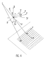
- the precession angle ⁇ around the axis Okay transforms the benchmark Oi j k in an intermediate landmark Or '' j '' k . It is associated with the rotation of the camera 4 and of the focal point F on the path T.
- the nutation angle ⁇ passes from the frame Or '' j '' k at the benchmark Or '' v '' w and is therefore a rotation around the axis defined by the vector u '; it expresses the inclination of the camera 4 relative to the axis of rotation 5.
- the proper rotation angle ⁇ is a rotation around the axis defined by the vector w and the origin 0 and which passes from the reference Or '' v '' w at the benchmark Or v w ; it expresses the inclination of the lines of the detectors 6 of the camera 4 with respect to the intersection of the plane of the path T with the detector.
- FIGS. 5 and 6 Vectors u , v and w , which are linked to the camera 4 and to the planes of the detectors Pm and of detection Pconverget, are illustrated in FIGS. 5 and 6: u and v belong to these planes and are oriented respectively in the direction of the rows and columns of the detector 6, and w is orthogonal to this plane and directed towards the focal point F.
- the point O is the origin of the coordinates of this coordinate system.
- the expression of the Radon transform is defined by formula (1): that of its derivative by formula (2): and the expressions of their inversions by formulas (3) and (4):
- the function which is the object of the transform is designated by f, the transform itself by Rf, M designates the points of the object frame and S 2 designates the set of unit vectors not from space.
- the vector OF is equal to pG u + qG v + FG w , or (x'F) u + (y'F) j + (zF) k
- ⁇ is the angle between - j 'and OF
- F ' is the orthogonal projection of the focal point F on the plane defined by the origin O and the vectors i and j
- equations (7) and (8) can be deduced quite easily for a circular trajectory of the focal point F
- other formulas can be deduced for other forms of the trajectory T:
- Certain parameters namely the coordinates from point Gd on the plane of detectors Pm, the distance focal length FGd and the sampling distances separating the acquisition points on the detector can be assessed by placing a grid or similar design in front of the detector plane, and to illuminate it with a planar source which can be a small reservoir filled with radioactive liquid in order to collect the image of the grid on the detector plane.
- the grid is integrated into a mechanism that allows it to be placed parallel to the detector plane and several distances. The image expands and therefore contracts on the plane of the Pm detectors depending on whether one approaches or away from the grid.
- the point Gd is the center dilations and contractions, magnification can be evaluated based on grid distances in terms of Pm detectors and at source and size of the grid image.
- the plate which bears the sources is placed at varying distances from detectors 6 by a set of spacers.
- angles ⁇ , ⁇ and ⁇ and the distance FG can be obtained by a series of experiments, in part described in a published article ("Estimation of geometrical parameters and collimator evaluation for con-beam tomography ", by Gullberg, Tsui, Crawford, Ballard and Hagius, published in 1990 in Medical Physics, n ° 1712), according to which there is at least one fixed and point radiation source and we do rotate the detector array to obtain a series source images. The comparison of these images in liaison with the places from where they were taken allows to determine the three angles and to deduce certain indications on the quality of collimation. A algorithm for minimizing uncertainties or least squares errors can be used.
- the difference between the detectors is given by the difference between the precession angles ⁇ evaluated according to the previous method for the same position of point sources.
- the invention can be applied very conveniently in cases where the focal point F and the camera 4 are driven on circular paths, but it can also be applied to multiple systems acquisition trajectories as in the two patents French cited. Finally, we can use it not only in algorithms using the Radon transform of the function used to reconstruct the image or the first derivative of this transform, but still in algorithms that involve a Hilbert transform of the Radon transform or of its first derivative.
Description
L'invention se rapporte à un procédé de reconstruction d'images tridimensionnelles d'un objet à l'aide de mesures utilisant un rayonnement conique et un réseau bidimensionnel de détecteurs.The invention relates to a reconstruction method three-dimensional images of an object using measurements using a conical radiation and a two-dimensional array of detectors.
Elle peut être considérée comme un perfectionnement des inventions décrites dans les brevets précédents attribués à la demanderesse (brevet européen 0292402 et brevets français de numéros d'enregistrement 90 14957 et 90 14958).It can be considered as an improvement of inventions described in previous patents attributed to the Applicant (European patent 0292402 and French number patents 90 14957 and 90 14958).
Un procédé de reconstruction de l'image d'un objet tridimensionnel à partir d'une série d'irradiations par un faisceau conique tournant autour de l'objet et qui vient frapper un écran couvert d'un réseau bidimensionnel de détecteurs est plus précisément décrit dans le premier de ces brevets : un algorithme utilisant l'inversion de ce qu'on appelle la dérivée première de la transformée de Radon de l'atténuation du rayonnement du faisceau à travers l'objet à reconstituer est utilisé.A method of reconstructing the image of an object three-dimensional from a series of irradiations by a conical beam revolving around the object and which strikes a screen covered with a network two-dimensional detector is more precisely described in the first of these patents: an algorithm using the inversion of what is called the first derivative of the Radon transform of the attenuation of the radiation from the beam through the object to be reconstructed is used.
Un article illustrant certains aspects de la reconstruction d'images tridimensionnelles avec l'emploi d'un faisceau conique d'irradiation est « Comparison of two three-dimensional X-ray cone-beam-reconstruction algorithms with circular source trajectories », par Rizo et al., paru dans « Journal of the Optical Society of America A » (Optics and Image Science), vol.8, n°10, oct.1991, USA, p.1639-1648: les méthodes par rétro-projection directe et par inversion de la transformé de Radon sont comparées, et les causes d'apparition d'artifacts dans les résultats sont examinées.An article illustrating certain aspects of reconstruction three-dimensional images using a conical beam is "Comparison of two three-dimensional X-ray cone-beam-reconstruction algorithms with circular source trajectories ”, by Rizo et al., published in "Journal of the Optical Society of America A" (Optics and Image Science), vol.8, n ° 10, Oct. 1991, USA, p.1639-1648: the methods by direct rear projection and by inversion of the Radon transform are compared, and the causes of occurrence of artifacts in the results are examined.
Les calculs exposés là ne sont cependant plus valables quand le réseau de détecteurs est mal placé par rapport à la trajectoire, ou quand le point focal est déplacé de sa position théorique, car la ligne de projection orthogonale du point focal sur le réseau de détecteurs (l'axe focal) ne passe plus par l'origine du repère d'objet. Une grande partie des calculs est en effet faite dans ce repère, qui est choisi sur l'axe de rotation du point focal et du réseau de détecteurs quand ceux-ci parcourent des trajectoires circulaires et dans le plan des trajectoires quand celles-ci sont coplanaires. Or ces situations sont extrêmement fréquentes car elles peuvent provenir de défauts d'alignement et de positionnement des mécanismes porteurs de la source et de l'écran, défauts qu'on n'a pas toujours le loisir de pouvoir corriger.The calculations exposed there are however no longer valid when the detector network is badly positioned relative to the trajectory, or when the focal point is moved from its theoretical position, because the line orthogonal projection of the focal point on the detector network (the axis focal) no longer passes through the origin of the object marker. A large part of calculations is in fact made in this coordinate system, which is chosen on the axis of rotation the focal point and the network of detectors when these pass through circular paths and in the plane of the trajectories when these are coplanar. These situations are extremely frequent because they can come from defects alignment and positioning of mechanisms carriers of the source and the screen, defects that we have not always the leisure to be able to correct.
Parfois ces situations sont même volontairement recherchées : un exemple classique est celui de l'examen de l'intérieur du crâne où le réseau de détecteurs parcourt une trajectoire située sur un cercle dont l'axe est parallèle à l'axe du patient.Sometimes these situations are even voluntarily sought: a classic example is that of the examination of the interior of the skull where the network of detectors travels a trajectory located on a circle whose axis is parallel to the patient's axis.
On désire utiliser l'appareil pour examiner des régions internes à des hauteurs différentes. Pour des raisons de coût et de simplicité, il est avantageux de pourvoir le réseau de détecteurs d'un collimateur unique pour toutes les situations d'examen.We want to use the device to examine internal regions at different heights. For for reasons of cost and simplicity, it is advantageous to provide the detector network with a collimator unique for all exam situations.
Or, les distorsions de la fonction de transfert de modulation qui accompagne les mesures et la reconstruction, et donc les distorsions de l'image, sont moins grandes dans le plan de la trajectoire du point focal, ce qui explique qu'on cherche à faire couper la région à examiner par ce plan.However, the distortions of the function of modulation transfer which accompanies the measurements and reconstruction, and therefore image distortions, are smaller in the plane of the trajectory of the focal point, which explains why we are trying to do cut the region to be examined by this plan.
On est alors amené à vouloir régler l'inclinaison du réseau de détecteurs sur le crâne du patient, en le disposant obliquement de façon que le point focal suive une trajectoire circulaire dont la hauteur est réglée en conséquence. De plus les détecteurs suivent ainsi au niveau des épaules des trajectoires de plus grand diamètre que ceux qui sont au niveau du sommet du crâne, ce qui permet d'enfoncer la tête plus profondément dans le dispositif et ainsi d'abaisser le plan de la trajectoire du point focal en direction du cou. Si le point focal correspond à une source matérielle de rayonnement, il suffit de la relier au réseau de détecteurs par une connexion mécanique rigide.We are then led to want to settle the inclination of the detector array on the skull of the patient, placing it obliquely so that the focal point follows a circular trajectory whose height is adjusted accordingly. Moreover, the detectors thus follow at the level of the shoulders of the trajectories of larger diameter than those which are at the top of the skull, which allows to push head deeper into the device and so lower the plane of the focal point trajectory by neck direction. If the focal point corresponds to a material source of radiation, just the connect to the detector network by a connection rigid mechanical.
Les calculs de reconstruction des images sont sensiblement plus compliqués dans ces conditions géométriques plus générales. Certaines publications les mentionnent ou les évoquent, au moins dans certains cas particuliers. Il est ainsi décrit comment procéder quand la reconstruction est effectuée par l'algorithme de Feldkamp dans lequel le faisceau conique est décomposé en un empilement de faisceaux plans en forme d'éventail (article de Manglos, Jaszczak et Greer "Cone-beam SPECT reconstruction with camera tilt", paru en 1989 dans "Physics in Medicine and Biology", n°34(5), p.625 et abrégé de Cao et Tsui paru en 1991 dans le "Journal of Nuclear Medicine", n°32(5), p.1066) ou par un algorithme de calcul itératif dans lequel la contribution de chaque point à l'atténuation du rayonnement est calculée à partir d'une valeur initiale en calculant à chaque étape des facteurs de correction déduits du rapport entre les mesures et les projections de l'estimation de la fonction obtenue à l'étape précédente (article de Manglos, Jaszczak et Mac Afee "Maximum likelihood reconstruction for cone-beam SPECT with camera tilt" paru en 1989 dans "IEEE Transactions on Nuclear Science", n°36(1). p.1117), mais rien ne semble avoir été effectué dans le cas où l'algorithme implique l'inversion de la transformée de Radon de la fonction ou de sa dérivée première.Image reconstruction calculations are significantly more complicated under these conditions more general geometric. Some publications mention or mention them, at least in some cases individuals. It is thus described how to proceed when the reconstruction is done by the algorithm of Feldkamp in which the conical beam is broken down into a stack of shaped flat beams range (article by Manglos, Jaszczak and Greer "Cone-beam SPECT reconstruction with camera tilt", published in 1989 in "Physics in Medicine and Biology", n ° 34 (5), p.625 and abridged by Cao and Tsui published in 1991 in the "Journal of Nuclear Medicine", n ° 32 (5), p.1066) or by an iterative calculation algorithm in which the contribution of each point to the mitigation of radiation is calculated from an initial value by calculating correction factors at each step deduced from the relationship between measurements and projections the estimate of the function obtained in step previous (article by Manglos, Jaszczak and Mac Afee "Maximum likelihood reconstruction for cone-beam SPECT with camera tilt "published in 1989 in" IEEE Transactions on Nuclear Science ", n ° 36 (1). p.1117), but nothing seems to have been performed in case the algorithm involves the reversal of the Radon transform of the function or its first derivative.
L'invention comble cette lacune, aussi bien dans le cas évoqué jusqu'à présent d'un faisceau conique émis d'une source ponctuelle externe et qui traverse l'objet en étant atténué que dans le cas parfaitement équivalent d'un réseau bidimensionnel de détecteurs collimatés vers un point focal unique derrière l'objet et sensible au rayonnement d'un produit émetteur de rayonnement qui imprègne l'objet, comme un marqueur contenu dans un liquide injecté au patient et qui se répand dans un organe à explorer après avoir été transporté par le réseau veineux. Il faut aussi observer que l'invention peut s'appliquer à un nombre quelconque de réseaux de détecteurs qui contribuent chacun à une partie de mesure et sont déplacés de quantités différentes.The invention fills this gap, as well in the case mentioned so far of a beam conical emitted from an external point source and which crosses the object being attenuated only in the case perfectly equivalent to a two-dimensional network of collimated detectors to a single focal point behind the object and sensitive to the radiation of a radiation emitting product which permeates the object, as a marker contained in a liquid injected into the patient and which spreads in an organ to be explored after being transported by the venous network. he it should also be noted that the invention can be applied to any number of detector networks that each contribute to a measurement portion and are displaced by different amounts.
L'invention concerne donc sous sa forme la plus générale un procédé de reconstruction d'images tridimensionnelles d'un objet défini par des valeurs prises par une fonction sur des points de l'objet, la fonction étant une propriété d'un rayonnement conique ayant un point focal et passant à travers l'objet, dans lequel la fonction est calculée par l'intermédiaire de sommes de la fonction sur des plans paramétrés passant par au moins un point de l'objet et définis dans un repère d'objet comportant une origine, le procédé comportant au moins une série de mesures prises dans différentes positions du point focal autour de l'objet, chaque somme de la fonction sur lesdits plans paramétrés dans le repère d'objet étant calculée à partir d'au moins une des mesures, chacune des mesures étant menée avec un réseau bidimensionnel de détecteurs du rayonnement orientés vers le point focal, et qui est déplacé sur une trajectoire circulaire autour de l'objet perpendiculairement à un axe de rotation, le point focal étant déplacé en même temps que le réseau de détecteurs de manière à se projeter orthogonalement sur un point fixe du réseau des détecteurs, un algorithme d'inversion étant utilisé pour retrouver la valeur prise par la fonction sur les points de l'objet à l'aide des sommes de la fonction sur les plans paramétrés, l'algorithme comprenant des étapes de détermination d'au moins une position du point focal appartenant à chacun desdits plans paramétrés, caractérisé en ce que l'axe focal, défini comme la ligne de projection orthogonale du point focal sur le réseau, passe à l'écart de l'origine et en ce que les étapes de détermination comprennent des calculs où interviennent des paramètres exprimant l'écart entre l'axe focal et l'origine et l'inclinaison entre l'axe focal et l'axe de rotation, cette inclinaison pouvant être quelconque.The invention therefore relates in its form to more generally an image reconstruction process three-dimensional object defined by values taken by a function on points of the object, the function being a property of a conical radiation having a focal point and passing through the object, in which the function is calculated through are of the function on parametric planes passing by at least one point of the object and defined in a object marker with an origin, the process involving at least one set of measures taken in different positions of the focal point around the object, each sum of the function on said planes parameterized in the object reference being calculated at from at least one of the measurements, each of the measurements being conducted with a two-dimensional network of detectors of radiation directed towards the focal point, and which is moved on a circular path around the object perpendicular to an axis of rotation, the focal point being moved at the same time as the network detectors so as to project orthogonally on a fixed point in the detector network, a inversion algorithm being used to find the value taken by the function on the points of the object using the sums of the function on the plans parameterized, the algorithm comprising steps of determination of at least one position of the focal point belonging to each of said configured plans, characterized in that the focal axis, defined as the orthogonal projection line of the focal point on the network, goes away from the origin and in that the determination steps include calculations where parameters expressing the difference between the focal axis and the origin and the inclination between the axis focal and axis of rotation, this inclination can be any.
La géométrie d'acquisition est décrite d'une
part par un jeu de paramètres intrinsèques à savoir la
distance focale FGd, la position Gd de la projection
orthogonale du point focal F sur le réseau de
détecteurs, les pas d'échantillonnage séparant les
détecteurs sur le réseau, et d'autre part par un jeu de
paramètres extrinsèques servant à positionner le point
focal et le réseau de détecteurs considérés par rapport
à l'axe de rotation, à savoir la position du point Od
projection conique de l'origine 0 sur le réseau de
détecteurs, la distance FG séparant le point focal et
le plan parallèle au détecteur et contenant l'origine 0
du repère d'objet, l'inclinaison du vecteur
perpendiculaire aux détecteurs par rapport à l'axe de
rotation, l'angle de rotation des lignes du réseau de
détecteur par rapport à la droite d'intersection du
plan de rotation du point focal avec le détecteur, la
position angulaire de la première acquisition.The acquisition geometry is described with
share by a set of intrinsic parameters namely the
focal length FGd, the position Gd of the projection
orthogonal of the focal point F on the network of
detectors, the sampling steps separating the
detectors on the network, and on the other hand by a set of
extrinsic parameters used to position the point
focal and the detector network considered in relation
to the axis of rotation, namely the position of the point Od
conical projection of the
On va maintenant décrire l'invention plus en détail à l'aide des figures suivantes annexées à titre illustratif et non limitatif :
- la figure 1 représente un exemple d'utilisation de l'invention ;
- et les figures 2 à 7 représentent les éléments géométriques mis en oeuvre et commentés dans la suite du texte.
- FIG. 1 represents an example of use of the invention;
- and Figures 2 to 7 show the geometric elements used and commented on in the text below.
La figure 1 représente donc un patient 1
étendu sur une table 2 et dont la tête 3 est examinée à
l'aide d'une camera 4 de rayons gamma, qui tourne
autour de la tête 3 selon un axe de rotation 5 établi
dans le sens de la hauteur du patient. La caméra 4 est
formée essentiellement d'un réseau plan (ou plus
généralement bidimensionnel) de détecteurs collimatés
de manière que les rayonnements qu'ils reçoivent
convergent tous vers un point focal F. Elle est fixée à
une structure mécanique circulaire non représentée -
mais dont les brevets cités fournissent des exemples -
de façon que le point focal F est solidaire de la
caméra 4 et parcourt une trajectoire T en forme
d'orbite circulaire perpendiculaire à l'axe de rotation
5 et dont le centre O' appartient à cet axe. La
trajectoire T s'étend ici à hauteur du cerveau du
patient 1. La caméra est inclinée d'un angle ( π / 2 - ξ)
par rapport à l'axe de rotation 5 ; l'angle ξ sera
défini plus précisément d'ici peu. Il est supposé égal
à π / 2
dans les brevets antérieurs ; l'appareillage
associé à cette invention est de préférence constitué
de façon à permettre de modifier l'angle ξ à volonté
pour déplacer la trajectoire T et la placer à hauteur
de la région de la tête 3 pour laquelle on manifeste de
l'intérêt, car une plus grande netteté est obtenue à
hauteur de cette trajectoire T.Figure 1 therefore represents a
Les points de l'image du patient sont définis
par leurs coordonnées dans un repère d'objet qui est un
repère cartésien d'origine 0 placé sur l'axe de
rotation 5 et défini par trois vecteurs directeurs : le
vecteur
Nous nous plaçons dans le cadre des méthodes
analytiques. La cartographie de l'activité
d'atténuation ou d'émission est décrite par une
fonction tridimensionnelle f représentant un ensemble
de coupes transverses parallèles. Pour chaque position
du point focal F, chaque détecteur 6 est relié au point
focal F par une droite de projection unique. La
projection en géométrie conique Xf associe à chacune de
ces droites une intégrale de la fonction f. La
reconstruction revient à résoudre le problème inverse,
c'est-à-dire à mettre en oeuvre l'enchaínement des
transformations nécessaires pour calculer f à partir de
Xf. L'outil d'analyse est la transformation de Radon
3D, définie comme l'ensemble des valeurs intégrales sur
les plans de l'espace, Dans la pratique, on se
restreint aux plans qui rencontrent l'objet. On associe
à chaque plan P son point caractéristique C, projection
orthogonale de l'origine O sur ce plan, et les
coordonnées sphériques (ρ,
Le point C, défini par ses coordonnées x, y
et z dans le repère d'objet (
Pour une position donnée du point focal F et pour un plan passant par ce point, nous avons établi une formule exacte, reliant la projection en géométrie conique Xf, à la dérivée première de la transformée de Radon R'f. L'opération principale consiste à sommer le long de la droite d'intersection du plan avec le détecteur les dérivées premières de la projection. Ceci permet d'affecter une valeur à tous les plans passant par cette position du plan focal. Après avoir procédé ainsi pour chaque incidence de mesure, l'opération de réarrangement consiste à redistribuer ces valeurs intégrales associées à chaque plan, du système de coordonnées lié aux positions du point focal, sur le système de coordonnées sphériques du domaine de Radon. Pour retrouver la fonction f, il reste à inverser la dérivée première de la transformée de Radon comme il est décrit dans le brevet mentionné en premier. L'algorithme procède en deux étapes, enchaínant d'abord des rétroprojections bidimensionnelles en géométrie parallèle pour chaque méridien du domaine de Radon, puis des rétroprojections bidimensionnelles en géométrie parallèle suivant les plans axiaux de l'objet.For a given position of the focal point F and for a plane passing through this point, we have established an exact formula, connecting the projection in geometry conic Xf, at the first derivative of the transform of Radon R'f. The main operation consists in summing the along the line of intersection of the plane with the detects the first derivatives of the projection. This allows to assign a value to all passing planes by this position of the focal plane. After proceeding thus for each measurement incidence, the operation of rearrangement is to redistribute these values integrals associated with each plane, of the system of coordinates linked to the focal point positions, on the Radon domain spherical coordinate system. To find the function f, it remains to reverse the first derivative of the Radon transform as it is described in the patent mentioned first. The algorithm proceeds in two stages, linking first two-dimensional overheads in geometry parallel for each meridian of the Radon domain, then two-dimensional overheads in parallel geometry along the axial planes of the object.
La trajectoire du point focal est usuellement circulaire. En caractérisant l'information acquise par les plans rencontrant la trajectoire, notre analyse met en évidence l'existence d'une zone d'ombre dans le domaine de Radon, liée aux plans qui rencontrent l'objet mais pas la trajectoire. Cette zone d'ombre est une source d'artefacts sur l'image reconstruite. Ceci explique pourquoi il est souhaitable que le plan focal soit centré sur la région à reconstruire. Notre algorithme permet d'atténuer ces distorsions en comblant cette zone d'ombre par interpolation. The trajectory of the focal point is usually circular. By characterizing the information acquired by the plans meeting the trajectory, our analysis puts highlight the existence of a gray area in the Radon domain, related to the plans that meet the object but not the trajectory. This gray area is a source of artifacts on the reconstructed image. This explains why it is desirable that the focal plane either centered on the region to be rebuilt. Our algorithm can mitigate these distortions by filling this gray area by interpolation.
Pour simplifier les calculs, on effectue un
paramétrage sur un plan de détection Pdèt, parallèle au
plan des détecteurs Pm auquel les détecteurs 6
appartiennent, et qui passe par l'origine 0. Les calculs
menés sur le plan de détection Pdét sont valables quelle
que soit la distance du plan des détecteurs Pm, à un
facteur de grossissement près. On désigne par A un point
quelconque du plan de détection Pdét, par G la projection
orthogonale du point focal F sur le plan de détection Pdét,
et par Od, Ad, Gd les points du plan des détecteurs Pm tels
que F,O et Od, d'une part, F,A et Ad ensuite, et F,G et Gd
d'autre part soient alignés ; mais dans le cas présent, G
et O sont distincts contrairement aux brevets précédents.
Les calculs menés sur le plan des détecteurs Pm ou, de
manière équivalente, sur le plan de détection Pdét
utilisent un repère d'origine 0 dont deux vecteurs
Trois angles de rotation peuvent être définis
(figure 4) pour décrire la position respective des repères
d'objet et d'acquisition. L'angle de précession ψ autour de
l'axe
L'angle de nutation ξ fait passer du repère
L'angle de rotation propre δ est une
rotation autour de l'axe défini par le vecteur
Une connaissance précise de δ et surtout de ξ
est nécessaire pour éviter les imprécisions de calcul
pendant la reconstruction. La connaissance exacte de ψ
est utile pour connaítre avec précision la position
exacte de l'image par rapport à l'objet, mais les
imprécisions sur cet angle n'ont pour conséquence
qu'une erreur d'orientation de l'image reconstruite.
Les vecteurs
L'expression de la transformée de Radon est
définie par la formule (1) :


La fonction qui fait l'objet de la
transformée est désignée par f, la transformée elle-même
par Rf, M désigne les points du repère d'objet et
S2 désigne l'ensemble des vecteurs unitaires
Si maintenant nous appelons A un point
quelconque de l'intersection d'un plan P(ρ,
Ici, O et G sont distincts, le vecteur 

En remarquant que C(ρ, Θ, ϕ) est identique à C(ρ, -Θ, ϕ+π), on peut se restreindre à n'utiliser que l'une d'entre ces équations, par exemple la (7).By noting that C (ρ, Θ, ϕ) is identical to C (ρ, -Θ, ϕ + π), we can restrict ourselves to using only one of these equations, for example (7).
Ces équations (7) et (8) permettent d'obtenir pour chaque point du volume caractéristique de l'objet défini par ses coordonnées sphériques ρ, et ϕ les valeurs des angles de précession ψ pour lesquels les mesures contenues dans le plan associé, et donc la dérivée première de la transformée de Radon en ce point peut être obtenue. Ces angles sont généralement au nombre de deux puisque les plans sont généralement sécants en deux points à une trajectoire circulaire.These equations (7) and (8) make it possible to obtain for each point of the characteristic volume of the object defined by its spherical coordinates ρ, and ϕ the values of the precession angles ψ for which the measures contained in the associated plan, and therefore the first derivative of the Radon transform at this point can be obtained. These angles are generally at number of two since plans are generally intersecting at two points on a circular path.
Les interpolations pour déduire les positions effectives du point focal F qui vont servir au calcul - il s'agit des positions voisines de cette position obtenue par calcul en utilisant les équations (7) et (8) et pour lesquelles des mesures ont été faites - ainsi que les rétro-projections pour reconstruire l'image en des points exprimés dans le repère d'objet à partir des sommes calculées sont identiques à celles du premier brevet.Interpolations to deduce positions of the focal point F which will be used for the calculation - these are positions close to this position obtained by calculation using equations (7) and (8) and for which measures have been taken - as well as the rear-projections to reconstruct the image at points expressed in the object frame to from the calculated sums are identical to those of first patent.
Il faut toutefois examiner comment il
convient d'effectuer les interpolations pour combler la
"zone d'ombre" des mesures avant d'accomplir les
calculs d'inversion. On se reporte pour cela à la
figure 7 : il est possible de démontrer facilement que,
si la trajectoire du point focal F est un cercle, les
points caractéristiques C' associés à des plans sur
lesquels la somme de la fonction f peut être mesurée
sont inclus dans un tore To obtenu par la révolution
d'un cercle de diamètre O'F autour du centre O' de la
trajectoire T. Si on désigne par ρ', et ϕ les
coordonnées sphériques du point C' à partir du centre
O', avec
Le principe adopté dans le brevet mentionné en premier (la différence par rapport au premier brevet est que O et O' sont distincts) (interpolation d'ordre zéro) consiste à associer à un point C' de la zone d'ombre la valeur mesurée sur un point d'une paire (C-ou C+) à la limite de la zone d'ombre, de même rayon ρ' et de même longitude ϕ ; les colatitudes de ces deux points sont +i et -i. On choisit le point dont la colatitude est la plus proche de , ici C+.The principle adopted in the mentioned patent first (the difference from the first patent is that O and O 'are distinct) (order interpolation zero) consists in associating with a point C 'of the zone shadow the value measured on a point of a pair (C-or C +) at the edge of the shadow zone, with the same radius ρ 'and of the same longitude ϕ; the colatitudes of these two points are + i and -i. We choose the point whose colatitude is the closest to , here C +.
Il suffit alors d'assimiler la valeur R'f
(ρ', , ϕ ) du point C' défini par ses coordonnées ρ',
et ϕ à partir de l'origine O' à la valeur mesurée
R'f ( ρi, i, ρi) où :


Tous ces calculs ne sont cependant accomplis avec succès que si les paramètres géométriques sont connus à l'avance avec une précision suffisante pour décrire correctement le système d'acquisition des mesures.However, all of these calculations are not completed successfully that if the geometric parameters are known in advance with sufficient precision to correctly describe the data acquisition system measures.
Certains paramètres, à savoir les coordonnées du point Gd sur le plan de détecteurs Pm, la distance focale FGd et les distances d'échantillonnage séparant les points d'acquisition sur le détecteur peuvent être évalués en disposant une grille ou un dessin analogue devant le plan des détecteurs, et à l'illuminer par une source plane qui peut être un petit réservoir rempli de liquide radioactif afin de recueillir l'image de la grille sur le plan des détecteurs. La grille est intégrée à un mécanisme qui permet de la placer parallèlement au plan des détecteurs et à plusieurs distances. L'image se dilate et se contracte donc sur le plan des détecteurs Pm suivant qu'on en approche ou qu'on en éloigne la grille. Le point Gd est le centre des dilatations et des contractions, le grossissement peut être évalué en fonction des distances de la grille au plan des détecteurs Pm et à la source et de la taille de l'image de la grille.Certain parameters, namely the coordinates from point Gd on the plane of detectors Pm, the distance focal length FGd and the sampling distances separating the acquisition points on the detector can be assessed by placing a grid or similar design in front of the detector plane, and to illuminate it with a planar source which can be a small reservoir filled with radioactive liquid in order to collect the image of the grid on the detector plane. The grid is integrated into a mechanism that allows it to be placed parallel to the detector plane and several distances. The image expands and therefore contracts on the plane of the Pm detectors depending on whether one approaches or away from the grid. The point Gd is the center dilations and contractions, magnification can be evaluated based on grid distances in terms of Pm detectors and at source and size of the grid image.
Un dispositif de ce genre est décrit dans l'article de Chang, intitulé "New Methods of Examining Gamma Camera Collimators" et paru en 1988 dans "The Journal of Nuclear Medicine", vol.29, n°5, p.676 à 683.Such a device is described in Chang's article, "New Methods of Examining Gamma Camera Collimators "and appeared in 1988 in" The Journal of Nuclear Medicine ", vol.29, n ° 5, p.676 to 683.
On peut remplacer la source lumineuse unique
et la grille par un réseau de sources aux noeuds d'une
grille virtuelle. La plaque qui porte les sources est
placée à des distances variables des détecteurs 6 par
un jeu d'entretoises.You can replace the single light source
and the grid by a network of sources at the nodes of a
virtual grid. The plate which bears the sources is
placed at varying distances from
Les angles ψ, ξ et δ et la distance FG peuvent être obtenus par une série d'expériences, en partie décrites dans un article publié ("Estimation of geometrical parameters and collimator evaluation for con-beam tomography", par Gullberg, Tsui, Crawford, Ballard et Hagius, paru en 1990 dans Medical Physics, n°1712), selon lesquelles on dispose au moins une source de rayonnement fixe et ponctuelle et on fait tourner le réseau de détecteurs pour obtenir une série d'images de la source. La comparaison de ces images en liaison avec les endroits d'où elles ont été prises permet de déterminer les trois angles et d'en déduire certaines indications sur la qualité de collimation. Un algorithme de minimisation des incertitudes ou des erreurs selon une méthode des moindres carrés peut être utilisé.The angles ψ, ξ and δ and the distance FG can be obtained by a series of experiments, in part described in a published article ("Estimation of geometrical parameters and collimator evaluation for con-beam tomography ", by Gullberg, Tsui, Crawford, Ballard and Hagius, published in 1990 in Medical Physics, n ° 1712), according to which there is at least one fixed and point radiation source and we do rotate the detector array to obtain a series source images. The comparison of these images in liaison with the places from where they were taken allows to determine the three angles and to deduce certain indications on the quality of collimation. A algorithm for minimizing uncertainties or least squares errors can be used.
Enfin, si on utilise plusieurs détecteurs, l'écart entre les détecteurs est donné par la différence entre les angles de précession ψ évalués selon la méthode précédente pour une même position des sources ponctuelles.Finally, if we use several detectors, the difference between the detectors is given by the difference between the precession angles ψ evaluated according to the previous method for the same position of point sources.
L'invention peut être appliquée très
commodément à des cas où le point focal F et la caméra
4 sont mus sur des trajectoires circulaires, mais elle
peut aussi être appliquée à des systèmes à plusieurs
trajectoires d'acquisition comme dans les deux brevets
français cités. Enfin, on peut l'utiliser non seulement
dans les algorithmes utilisant la transformée de Radon
de la fonction qui sert à la reconstruction de l'image
ou la dérivée première de cette transformée, mais
encore dans les algorithmes qui comportent une
transformée de Hilbert de la transformée de Radon ou de
sa dérivée première.The invention can be applied very
conveniently in cases where the focal point F and the
Claims (7)
- Process for the reconstruction of three-dimensional images of an object (3) defined by values assumed by a function (f) on points (M) of the object, the function being a property of a conical radiation having a focal point (F) and passing through the object (3), in which the function (f) is calculated using sums of the function (f) on planes (P) passing through the object (3) and parametrized by coordinates (ρ, , ϕ) defined in an object mark (O,
i ,j ,k ) having an origin (0);
the process comprising:characterized in that:a displacement on a trajectory about the object (3) and a rotation axis (5) of a bidimensional array (4) of detectors (6) oriented towards the focal point (F), which is displaced with the array (4) and is orthogonally projected through a focal axis onto a fixed point (Gd) of the array;measurements of the function (f) by detectors (6) at at least one series of acquisition positions, associated with precession angles (ψ) about the object (3) of the array (4) and the focal point (F);determination calculations associating with the planes (P) precession angles (ψ) of the array (4) by formulas making use of the coordinates (ρ, , ϕ);calculations of the sums of the measurements on planes (P);calculations on the sums by an inversion algorithm for obtaining the values assumed by the function (f) on the object points (M);the focal axis passes to the side of the origin (O) of the object mark;the determination calculation formulas use at least one angle (ξ) between the focal axis and the rotation axis and a displacement (pG, qG, FG) between the focal point (F) and the origin (O) of the object mark, said displacement being measured in directions (u ,v ,w ) of an acquisition mark linked with the array (4) and whereof one of the directions corresponds to the focal axis. - Process according to claim 1, characterized in that the determination calculations use an angle (ξ) between rows of detectors (6) of the array (4) and a plane perpendicular to the rotation axis (5).
- Process according to either of the claims 1 or 2, characterized in that the formulas incorporate at least one of the formulas (7) and (8), the trajectory being circular.
- Process according to one of the claims 1 to 3, characterized in that it comprises a Hilbert transform.
- Process according to any one of the claims 1 to 4, characterized in that the object is the head of a patient (1) and the rotation axis (5) is an axis established in the height direction of the patient and the angle (ξ) between the focal axis and the rotation axis is freely chosen.
- Process according to claim 5, characterized in that the angle (ξ) between the focal axis and the rotation axis is advantageously 90°.
- Process according to any one of the claims 1 to 6, characterized in that it comprises a compliment stage of a group of quantities consisting of sums, or quantities obtained from said sums, measurements on planes (P) by values parametrized by the coordinates (ρ, , ϕ) of the same nature as the coordinates of the planes (P) and resulting from the interpolation of the quantities of the group as a function of said coordinates.
Applications Claiming Priority (2)
| Application Number | Priority Date | Filing Date | Title |
|---|---|---|---|
| FR9206844A FR2692061B1 (en) | 1992-06-05 | 1992-06-05 | METHOD FOR RECONSTRUCTING THREE-DIMENSIONAL IMAGES OF AN OBJECT BY MEASUREMENTS USING CONICAL RADIATION AND A TWO-DIMENSIONAL ARRAY OF DETECTORS. |
| FR9206844 | 1992-06-05 |
Publications (2)
| Publication Number | Publication Date |
|---|---|
| EP0573364A1 EP0573364A1 (en) | 1993-12-08 |
| EP0573364B1 true EP0573364B1 (en) | 1999-10-27 |
Family
ID=9430483
Family Applications (1)
| Application Number | Title | Priority Date | Filing Date |
|---|---|---|---|
| EP93401423A Expired - Lifetime EP0573364B1 (en) | 1992-06-05 | 1993-06-03 | Method for the reconstruction of 3D images of an object from measures using a cone beam source and a two dimensional detector array |
Country Status (6)
| Country | Link |
|---|---|
| US (1) | US5408511A (en) |
| EP (1) | EP0573364B1 (en) |
| JP (1) | JPH0696191A (en) |
| DE (1) | DE69326857T2 (en) |
| FR (1) | FR2692061B1 (en) |
| IL (1) | IL105732A (en) |
Families Citing this family (15)
| Publication number | Priority date | Publication date | Assignee | Title |
|---|---|---|---|---|
| US5515409A (en) * | 1994-12-22 | 1996-05-07 | General Electric Company | Helical interpolative algorithm for image reconstruction in a CT system |
| FR2736455B1 (en) * | 1995-07-03 | 1997-08-08 | Commissariat Energie Atomique | METHOD FOR RECONSTRUCTING A 3D IMAGE WITH IMPROVED CONTRAST AND RESOLUTION AND APPLICATION OF THIS PROCESS TO PROVIDING AN ATTENUATION MAPPING OF AN OBJECT |
| JP4258855B2 (en) * | 1998-03-16 | 2009-04-30 | コニカミノルタホールディングス株式会社 | Radiographic imaging display method and radiographic imaging display device |
| FI105448B (en) * | 1999-03-18 | 2000-08-31 | Instrumentarium Oy | Method and apparatus for X-ray imaging of head and neck |
| JP2002085389A (en) * | 2000-07-14 | 2002-03-26 | Konica Corp | X-ray imaging system and method |
| US6463117B1 (en) * | 2000-11-22 | 2002-10-08 | Ge Medical Systems Global Technology Company, Llc | Methods and apparatus for tilted helical image reconstruction in CT imaging |
| US6473488B2 (en) * | 2000-12-20 | 2002-10-29 | Cedara Software Corp. | Three dimensional image reconstruction from single plane X-ray fluorograms |
| JP4298205B2 (en) * | 2001-02-12 | 2009-07-15 | シーメンス アクチエンゲゼルシヤフト | Method and computer tomography apparatus for computer tomography |
| US6983034B2 (en) * | 2003-02-14 | 2006-01-03 | University Of Iowa Research Foundation | Methods and devices for CT reconstruction using a grangeat approach |
| JP4756849B2 (en) * | 2004-11-05 | 2011-08-24 | 朝日レントゲン工業株式会社 | Cone beam X-ray CT imaging system for head and neck |
| US20100001192A1 (en) * | 2008-07-07 | 2010-01-07 | Kai Lange | Gamma camera system with slanted detectors, slanted collimators, and a support hood |
| US8952333B2 (en) * | 2009-11-02 | 2015-02-10 | Virginia Tech Intellectual Properties, Inc. | Methods for improved single photon emission computed tomography using exact and stable region of interest reconstructions |
| US9091628B2 (en) | 2012-12-21 | 2015-07-28 | L-3 Communications Security And Detection Systems, Inc. | 3D mapping with two orthogonal imaging views |
| US9704300B2 (en) * | 2015-03-06 | 2017-07-11 | Siemens Medical Solutions Usa, Inc. | Detection of anatomy orientation using learning-based regression |
| CN109166168B (en) * | 2018-09-04 | 2023-02-14 | 上海同岩土木工程科技股份有限公司 | Rapid construction method for three-dimensional layout of tunnel lining structure |
Family Cites Families (6)
| Publication number | Priority date | Publication date | Assignee | Title |
|---|---|---|---|---|
| JPS61220628A (en) * | 1985-03-28 | 1986-09-30 | 株式会社 日立メデイコ | X-ray dynamic image measuring apparatus |
| US4752691A (en) * | 1986-06-23 | 1988-06-21 | Siemens Gammasonics, Inc. | Method and apparatus for compensating finite angular resolution in collimated scintillation cameras |
| JPH084586B2 (en) * | 1989-02-07 | 1996-01-24 | 浜松ホトニクス株式会社 | CT device |
| JPH0619438B2 (en) * | 1989-04-04 | 1994-03-16 | 株式会社東芝 | Emission CT device |
| US5001347A (en) * | 1989-09-27 | 1991-03-19 | Siemens Gammasonics, Inc. | Focussing collimators for use in rotational camera transaxial SPECT in which the camera head is inclined with respect to the axis of rotation |
| US5170439A (en) * | 1991-06-11 | 1992-12-08 | Picker International, Inc. | Cone beam reconstruction using combined circle and line orbits |
-
1992
- 1992-06-05 FR FR9206844A patent/FR2692061B1/en not_active Expired - Lifetime
-
1993
- 1993-05-18 IL IL10573293A patent/IL105732A/en not_active IP Right Cessation
- 1993-05-21 US US08/065,142 patent/US5408511A/en not_active Expired - Lifetime
- 1993-06-03 EP EP93401423A patent/EP0573364B1/en not_active Expired - Lifetime
- 1993-06-03 DE DE69326857T patent/DE69326857T2/en not_active Expired - Lifetime
- 1993-06-04 JP JP5158091A patent/JPH0696191A/en not_active Withdrawn
Also Published As
| Publication number | Publication date |
|---|---|
| FR2692061A1 (en) | 1993-12-10 |
| DE69326857D1 (en) | 1999-12-02 |
| US5408511A (en) | 1995-04-18 |
| FR2692061B1 (en) | 1994-07-22 |
| JPH0696191A (en) | 1994-04-08 |
| DE69326857T2 (en) | 2000-05-18 |
| IL105732A0 (en) | 1993-09-22 |
| EP0573364A1 (en) | 1993-12-08 |
| IL105732A (en) | 1996-07-23 |
Similar Documents
| Publication | Publication Date | Title |
|---|---|---|
| EP0573364B1 (en) | Method for the reconstruction of 3D images of an object from measures using a cone beam source and a two dimensional detector array | |
| EP0492895B1 (en) | Reconstructing 3-D images | |
| EP0389333B1 (en) | Process for the acquisition of radiological data and the reconstruction of structures of an irradiated body | |
| EP1222636B1 (en) | Three-dimensional statistic reconstruction of surfaces | |
| US6580777B1 (en) | X-ray CT apparatus | |
| EP1390774B1 (en) | Reconstruction method for a high resolution photon emission computed tomographic imaging tool | |
| US6574297B2 (en) | System and method for image reconstruction in a cone beam imaging system | |
| FR2613487A1 (en) | METHOD FOR OBTAINING INFORMATION ON THE LIMITATIONS OF AN OBJECT IN COMPUTERIZED TOMOGRAPHY WITH A LIMITED ANGLE | |
| EP2309462B1 (en) | Radiographic imaging method and device for three-dimensional reconstruction with low dose of irradiation | |
| EP0611181A1 (en) | Three-dimensional picture reconstruction process of evolving object | |
| FR2700909A1 (en) | Automatic method and device for geometric calibration of an X-ray imaging system | |
| JPH0793924B2 (en) | Reconstruction method of tomographic image using radiation crossing plane | |
| JP4342164B2 (en) | Computed tomography equipment | |
| FR2849241A1 (en) | Medical radiographic imaging method for measuring 3D bone density distributions, in which 3D radiological data are processed in conjunction with a 3D generic model of a bone being imaged | |
| EP0488889A1 (en) | Method and apparatus for reconstructing three-dimensional images of an object using two acquisition circular paths | |
| CN102488528B (en) | Correcting method for geometric parameters of tomography | |
| US8861829B2 (en) | Method and system for reconstruction of tomographic images | |
| EP0488888B1 (en) | Method and apparatus for reconstructing three-dimensional images of an object using two common-axis circular paths | |
| FR3042881B1 (en) | ROTATING COLLIMATOR FOR DETERMINING THE POSITION OF AN ELEMENT PROVIDED WITH SENSORS IN AN X-RAY IMAGING SYSTEM | |
| FR2696027A1 (en) | Method for reconstructing three-dimensional images of a region of interest of an object, and appropriate installation. | |
| EP0627702A1 (en) | Method and device for reconstruction of 3D images | |
| EP3153102A1 (en) | Method for determining a dose of radiation applied to a patient | |
| WO2020254653A1 (en) | Compton camera and method for campton 3d imaging | |
| EP0741308A1 (en) | Method for obtaining the emission co-ordinates of a body corrected for attenuation | |
| EP0751485A1 (en) | Method of producing a flux conforming device for acquiring transmission images of an object |
Legal Events
| Date | Code | Title | Description |
|---|---|---|---|
| PUAI | Public reference made under article 153(3) epc to a published international application that has entered the european phase |
Free format text: ORIGINAL CODE: 0009012 |
|
| AK | Designated contracting states |
Kind code of ref document: A1 Designated state(s): DE GB NL |
|
| 17P | Request for examination filed |
Effective date: 19940511 |
|
| 17Q | First examination report despatched |
Effective date: 19970807 |
|
| GRAG | Despatch of communication of intention to grant |
Free format text: ORIGINAL CODE: EPIDOS AGRA |
|
| GRAG | Despatch of communication of intention to grant |
Free format text: ORIGINAL CODE: EPIDOS AGRA |
|
| GRAH | Despatch of communication of intention to grant a patent |
Free format text: ORIGINAL CODE: EPIDOS IGRA |
|
| GRAH | Despatch of communication of intention to grant a patent |
Free format text: ORIGINAL CODE: EPIDOS IGRA |
|
| GRAA | (expected) grant |
Free format text: ORIGINAL CODE: 0009210 |
|
| RTI1 | Title (correction) |
Free format text: METHOD FOR THE RECONSTRUCTION OF 3D IMAGES OF AN OBJECT FROM MEASURES USING A CONE BEAM SOURCE AND A TWO DIMENSIONAL DETECTOR ARRAY |
|
| AK | Designated contracting states |
Kind code of ref document: B1 Designated state(s): DE GB NL |
|
| PG25 | Lapsed in a contracting state [announced via postgrant information from national office to epo] |
Ref country code: NL Free format text: LAPSE BECAUSE OF FAILURE TO SUBMIT A TRANSLATION OF THE DESCRIPTION OR TO PAY THE FEE WITHIN THE PRESCRIBED TIME-LIMIT Effective date: 19991027 |
|
| REF | Corresponds to: |
Ref document number: 69326857 Country of ref document: DE Date of ref document: 19991202 |
|
| GBT | Gb: translation of ep patent filed (gb section 77(6)(a)/1977) |
Effective date: 20000110 |
|
| NLV1 | Nl: lapsed or annulled due to failure to fulfill the requirements of art. 29p and 29m of the patents act | ||
| PLBE | No opposition filed within time limit |
Free format text: ORIGINAL CODE: 0009261 |
|
| STAA | Information on the status of an ep patent application or granted ep patent |
Free format text: STATUS: NO OPPOSITION FILED WITHIN TIME LIMIT |
|
| 26N | No opposition filed | ||
| REG | Reference to a national code |
Ref country code: GB Ref legal event code: IF02 |
|
| PGFP | Annual fee paid to national office [announced via postgrant information from national office to epo] |
Ref country code: GB Payment date: 20120525 Year of fee payment: 20 |
|
| PGFP | Annual fee paid to national office [announced via postgrant information from national office to epo] |
Ref country code: DE Payment date: 20120629 Year of fee payment: 20 |
|
| REG | Reference to a national code |
Ref country code: DE Ref legal event code: R071 Ref document number: 69326857 Country of ref document: DE |
|
| REG | Reference to a national code |
Ref country code: GB Ref legal event code: PE20 Expiry date: 20130602 |
|
| PG25 | Lapsed in a contracting state [announced via postgrant information from national office to epo] |
Ref country code: DE Free format text: LAPSE BECAUSE OF EXPIRATION OF PROTECTION Effective date: 20130604 Ref country code: GB Free format text: LAPSE BECAUSE OF EXPIRATION OF PROTECTION Effective date: 20130602 |