EP0573302B1 - Frictionless bearing chassis dynamometer - Google Patents
Frictionless bearing chassis dynamometer Download PDFInfo
- Publication number
- EP0573302B1 EP0573302B1 EP93304356A EP93304356A EP0573302B1 EP 0573302 B1 EP0573302 B1 EP 0573302B1 EP 93304356 A EP93304356 A EP 93304356A EP 93304356 A EP93304356 A EP 93304356A EP 0573302 B1 EP0573302 B1 EP 0573302B1
- Authority
- EP
- European Patent Office
- Prior art keywords
- bearing
- speed
- outer race
- input shaft
- bearings
- Prior art date
- Legal status (The legal status is an assumption and is not a legal conclusion. Google has not performed a legal analysis and makes no representation as to the accuracy of the status listed.)
- Expired - Lifetime
Links
- 238000012360 testing method Methods 0.000 claims description 15
- 238000000034 method Methods 0.000 claims description 7
- 230000000712 assembly Effects 0.000 description 28
- 238000000429 assembly Methods 0.000 description 28
- 230000008901 benefit Effects 0.000 description 7
- 238000013461 design Methods 0.000 description 7
- 239000000314 lubricant Substances 0.000 description 5
- 238000012423 maintenance Methods 0.000 description 4
- 230000000694 effects Effects 0.000 description 3
- 230000003071 parasitic effect Effects 0.000 description 3
- 238000010521 absorption reaction Methods 0.000 description 2
- 230000033228 biological regulation Effects 0.000 description 2
- 230000001276 controlling effect Effects 0.000 description 2
- 238000012937 correction Methods 0.000 description 2
- 230000008878 coupling Effects 0.000 description 2
- 238000010168 coupling process Methods 0.000 description 2
- 238000005859 coupling reaction Methods 0.000 description 2
- 238000005516 engineering process Methods 0.000 description 2
- 238000005259 measurement Methods 0.000 description 2
- 230000000737 periodic effect Effects 0.000 description 2
- 238000005096 rolling process Methods 0.000 description 2
- 238000004088 simulation Methods 0.000 description 2
- 239000004215 Carbon black (E152) Substances 0.000 description 1
- UGFAIRIUMAVXCW-UHFFFAOYSA-N Carbon monoxide Chemical compound [O+]#[C-] UGFAIRIUMAVXCW-UHFFFAOYSA-N 0.000 description 1
- 238000013459 approach Methods 0.000 description 1
- 230000005540 biological transmission Effects 0.000 description 1
- 229910002091 carbon monoxide Inorganic materials 0.000 description 1
- 230000008859 change Effects 0.000 description 1
- 238000006243 chemical reaction Methods 0.000 description 1
- 150000001875 compounds Chemical class 0.000 description 1
- 238000010276 construction Methods 0.000 description 1
- 239000013078 crystal Substances 0.000 description 1
- 230000001186 cumulative effect Effects 0.000 description 1
- 230000001419 dependent effect Effects 0.000 description 1
- 238000010586 diagram Methods 0.000 description 1
- 230000008030 elimination Effects 0.000 description 1
- 230000007613 environmental effect Effects 0.000 description 1
- 230000004907 flux Effects 0.000 description 1
- 239000004519 grease Substances 0.000 description 1
- 238000010438 heat treatment Methods 0.000 description 1
- 229930195733 hydrocarbon Natural products 0.000 description 1
- 150000002430 hydrocarbons Chemical class 0.000 description 1
- 230000006698 induction Effects 0.000 description 1
- 230000007246 mechanism Effects 0.000 description 1
- 229910052751 metal Inorganic materials 0.000 description 1
- 239000002184 metal Substances 0.000 description 1
- 238000012544 monitoring process Methods 0.000 description 1
- 239000010453 quartz Substances 0.000 description 1
- 230000009467 reduction Effects 0.000 description 1
- 230000001105 regulatory effect Effects 0.000 description 1
- 230000004044 response Effects 0.000 description 1
- VYPSYNLAJGMNEJ-UHFFFAOYSA-N silicon dioxide Inorganic materials O=[Si]=O VYPSYNLAJGMNEJ-UHFFFAOYSA-N 0.000 description 1
- 238000012546 transfer Methods 0.000 description 1
- 238000010792 warming Methods 0.000 description 1
- 238000003466 welding Methods 0.000 description 1
Images


Classifications
-
- F—MECHANICAL ENGINEERING; LIGHTING; HEATING; WEAPONS; BLASTING
- F16—ENGINEERING ELEMENTS AND UNITS; GENERAL MEASURES FOR PRODUCING AND MAINTAINING EFFECTIVE FUNCTIONING OF MACHINES OR INSTALLATIONS; THERMAL INSULATION IN GENERAL
- F16C—SHAFTS; FLEXIBLE SHAFTS; ELEMENTS OR CRANKSHAFT MECHANISMS; ROTARY BODIES OTHER THAN GEARING ELEMENTS; BEARINGS
- F16C19/00—Bearings with rolling contact, for exclusively rotary movement
- F16C19/54—Systems consisting of a plurality of bearings with rolling friction
- F16C19/55—Systems consisting of a plurality of bearings with rolling friction with intermediate floating or independently-driven rings rotating at reduced speed or with other differential ball or roller bearings
-
- G—PHYSICS
- G01—MEASURING; TESTING
- G01M—TESTING STATIC OR DYNAMIC BALANCE OF MACHINES OR STRUCTURES; TESTING OF STRUCTURES OR APPARATUS, NOT OTHERWISE PROVIDED FOR
- G01M17/00—Testing of vehicles
- G01M17/007—Wheeled or endless-tracked vehicles
- G01M17/0072—Wheeled or endless-tracked vehicles the wheels of the vehicle co-operating with rotatable rolls
Definitions
- This invention relates to chassis dynamometers, and more particularly to a frictionless chassis dynamometer incorporating concentrically disposed inner and outer roller bearings operable to cancel or mask frictional forces introduced by the bearings during operation of the dynamometer.
- Chassis dynamometers are used in a wide variety of applications, and particularly in connection with the testing of motor vehicle engine emissions pursuant to Environmental Protection Agency (EPA) emissions regulations for motor vehicles.
- EPA Environmental Protection Agency
- Such dynamometers typically incorporate one or more "rolls" which are driven by one or more wheels of the vehicle under test.
- the rolls are typically coupled to an input shaft of some form of power absorption, or exchange, device which provides a controlled degree of rolling resistance to the rolls to simulate the road load and inertia forces normally encountered during vehicle operation.
- the input shaft of the power absorption device and/or the rolls is typically supported by an annular roller bearing which is interposed between the input shaft of the power exchange device and a frame portion of the dynamometer.
- the bearing supports the input shaft and enables rotational movement of the input shaft relative to the fixed frame portion.
- the dynamometer typically must be run for at least about twenty to thirty minutes to "warm-up" the bearings. It is then presumed that the friction of the bearings will vary with speed in accordance with known friction versus speed characteristics. These friction characteristics are stored in an external controller memory and then mathematically subtracted out from measurement data obtained by the dynamometer by an external controller by known friction compensation algorithms.
- the drawback with this approach is that the friction of the bearings varies not only with speed but also with the temperature of the bearings, the loading on the bearings, and the duration of operating time intervals. These factors have proven difficult to accurately compensate for with correction algorithms.
- friction compensation algorithms do not allow for variations in the degree of compensation being applied during an actual vehicle simulation test, only during execution of the compensation program itself. Accordingly, unaccounted for changes in vehicle loading or ambient room temperatures that occur during a vehicle simulation test would not be compensated for by conventional friction compensation algorithms.
- Temperature in particular, can prove especially difficult to determine and compensate for. More and more applications are requiring that dynamometers be operated in a cold testing facility (CTF) to enable carbon monoxide emissions to be measured at cold temperatures in accordance with EPA regulations. Since such "cold rooms” are also frequently used at significantly higher temperatures, the temperatures of the component parts of the dynamometer, and particularly the bearings, do not “settle” or become stable quickly. This is due in large part to the mass of the various components of the dynamometer, and the fact that many components, such as the rolls and bearings, are made from metal and thus form excellent paths for the transfer of heat and cold.
- CTF cold testing facility
- the bearings supporting the rolls and/or input shaft must also be selected with precision as a foremost consideration, rather than high durability. This usually means that high cost bearings must be used that introduce a minimum amount of friction, at the expense of lower cost bearings that have high durability but which introduce a greater amount of friction. Since higher precision, lower durability bearings are typically used, bearing maintenance and failure are higher than what would otherwise be experienced with high durability bearings. Moreover, periodic friction calibrations are typically required to compensate for variations in friction of the bearings resulting from wear.
- US-A-4 077 255 discloses a chassis dynamometer in accordance with the preamble of claim 1.
- a chassis dynamometer apparatus comprising:
- a chassis dynamometer which oppose rotational movement of a roller of the dynamometer as the roller is driven by the driving wheels of a vehicle under test, said method comprising:
- the dynamometer includes at least one roll which is adapted to engage the driving wheel of a vehicle.
- the roll is fixedly coupled to an input shaft of a power exchange means which simulates the road load and inertia forces which must be overcome by the vehicle during normal operation of the vehicle.
- the input shaft is supported by concentrically disposed inner and outer bearings, with an inner race of the inner bearing supporting the input shaft and an outer race of the outer bearing being supported by a frame portion of the dynamometer.
- an inner/outer race member which forms an outer race for the inner bearing and an inner race for the outer bearing.
- the inner/outer race member is further coupled to a bearing drive motor which is responsive to the changing rotational speed of the input shaft.
- the bearing drive motor is controlled such that it drives the inner/outer race member in the same direction of rotation as the input shaft, and preferably at a speed alternately slower and faster than the input shaft speed.
- the dynamometer includes a pair of laterally spaced apart rolls which each engage and are each driven by the front or rear wheels of a vehicle.
- a power exchange means in the form of a well known Power Exchange Unit (PEU) is disposed between the rolls and includes an input shaft which extends and is fixedly secured at its opposite ends to each of the rolls.
- Each end of the input shaft includes an inner annular bearing concentrically disposed thereover and an outer annular bearing concentrically disposed over each inner annular bearing.
- an inner/outer race member Interposed in between each pair of inner and outer bearings is an inner/outer race member which forms an outer race for the inner bearing and an inner race for the outer bearing.
- Each of the inner/outer race members are operably coupled to independent bearing drive motors.
- One of the bearing drive motors drives its respective inner/outer race member in the same direction of rotation as the input shaft and at a rotational speed that is slightly less than the rotational speed of the input shaft.
- the other bearing drive motor drives its respective inner/outer race member in the same direction and at a rotational speed that is slightly greater than the rotational speed of the input shaft.
- the inner/outer race member that was being driven at a speed slightly slower than the input shaft speed is then driven at a speed slightly faster than the input shaft, while the opposite inner/outer race member which was driven at a speed slightly faster than the input shaft is then driven at a rotational speed slightly slower than the input shaft.
- This operation is alternated in accordance with a predetermined time interval to substantially completely eliminate frictional forces introduced by the bearings when more than one pair of inner and outer bearings is employed.
- the preferred embodiments of the invention provide several significant advantages over conventional dynamometer designs. Initially, the "warm-up" time normally otherwise needed before the bearings become stable is virtually eliminated. Thus, the dynamometer of the present invention can begin providing test data almost immediately after start-up and does not require the typical twenty to thirty minute warm-up time needed by other dynamometers.
- lubricants can be selected which are high in durability rather than lubricants designed to minimize friction at the expense of durability. Accordingly, lower cost lubricants may be purchased which provide greater durability and help lower the frequency of periodic maintenance and/or calibration of the bearings.
- the dynamometer of the present invention also provides numerous operational benefits over presently existing bearing configurations. Bearing friction loss remains virtually zero over variable operating temperatures, varying loads, and varying operating time intervals. The bearings are stable almost immediately upon start-up of the dynamometer and remain stable regardless of changes in ambient room temperature or loads placed upon the dynamometer.
- the embodiments of the present invention are particularly well suited for use in cold testing facilities where frequent changes in ambient temperature of the room can significantly affect the stability of the bearings, and where compensating for such temperature variations is often difficult, if not impossible.
- the overall reliability of the dynamometer of the present invention is increased because of the virtually eliminated bearing friction, which would normally tend to hasten wear of the bearings. Additionally, by incorporating two bearings, one concentrically disposed within the other, the dynamometer will still be operational if one of the bearings seizes up during operation. For example, if the inner bearing seizes, the input shaft of the power exchange means would still be able to rotate upon the outer bearing.
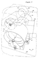
- Dynamometer 10 generally includes a frame 12, first and second coaxially aligned and laterally spaced apart 1.22 m (48 inch) diameter rolls 14 and 16; a power exchange means in the form of a power exchange unit (PEU) 18 disposed in between the rolls 14 and 16 and coaxially aligned with the longitudinal axes of rotation of the rolls 14 and 16; and first and second bearing drive motor assemblies 20 and 22, respectively.
- a conventional, electro-optical encoder assembly 23 is operationally coupled to the PEU 18.
- a rear end of a vehicle 24 is illustrated in phantom showing how wheels 26 of the vehicle 24 engage outer surfaces of the rolls 14,16 to drive the rolls 14,16.
- the dynamometer 10 is typically secured to the floor 28 of a pit 30, although it could be mounted at ground level provided appropriate structure in the form of ramps or the like are provided for driving the vehicle up to a position wherein wheels 26 can engage the rolls 14,16.
- the PEU 18 can be seen to include an input shaft 32 having a first end 32a and an opposite, or second, end 32b.
- the PEU 18 includes a conventional load cell 18a and comprises an AC induction motor employing flux vector power conversion technology, and is commercially available from the Corporation of (city, state).
- This form of PEU has been found to provide faster response time, better zero-speed control, and generally lower maintenance than PEU's employing conventional DC technology.
- placement of the PEU 18 between the rolls 14,16, rather than outside of the rolls 14,16 provides for a more compact arrangement than most previously designed dynamometers.
- the load cell 18a of the PEU 18 enables varying loads to be simulated as the wheels 26 drive the rolls 14,16.
- the load cell 18a also enables various performance parameters such as the torque exerted on the rolls 14,16 (i.e., the "roll torque") to be measured.
- a first bearing drive hub 34 is disposed concentrically over end 32a of input shaft 32 and rotationally supported thereon by a bearing 34a.
- the bearing drive hub 34 is coupled via a pulley 36 and a belt 38 with a pulley 40.
- the pulley 40 is in turn coupled to a motor 20a of the first bearing motor drive assembly 20.
- the second end 32b of input shaft 32 is circumscribed by a second bearing drive hub 42, which is likewise rotationally supported by a bearing (not shown).
- the second bearing drive hub 42 is in turn coupled to a pulley 44 in contact with a drive belt 46.
- the drive belt 46 is engaged with a pulley 48 which is driven by a motor 22a of the second bearing motor drive assembly 22.
- the entire dynamometer 10 is secured to the floor 28 of the pit 30 by a plurality of conventional alignment/fixture assemblies extending through portions of the frame 12.
- the bearing drive motor assemblies 20,22 each include their own motor speed controller which is commercially available from ( city , state ). Also, while the bearing drive motors 20a,22a have been illustrated as being coupled via conventional pulleys and drive belts to the bearing drive hubs 34,42, it will be appreciated that this coupling could be effected in numerous ways. For example, conventional sprockets and chains could be employed. Alternatively, the drive motors 20 and 22 could have their output shafts coupled directly to the bearing drive hubs 34,42, provided suitable motors are employed which can be disposed concentrically with the input shaft 32.
- Rolls 14 and 16 together, provide a base mechanical inertia of preferably about 1350 kg (3,000 lbs.), and include members 14a and 16a, respectively.
- Member 14a is fixedly secured via threaded bolts 52 to the first end 32a of the input shaft 32.
- Member 16a is similarly secured to the second end 32b of input shaft 32 via bolts 54.
- An encoder shaft 23a of encoder assembly 23 is further fixedly secured to the first end 32a of the input shaft 32.
- the input shaft 32 is supported upon frame portions 56 and 58 of the frame 12, and by first and second bearing assemblies 60 and 62, respectively, of the present invention.
- the bearing assemblies 60,62 rest upon inner surfaces 56a and 58a of the frame portions 56 and 58, respectively, and are secured thereto by pillow blocks 64 and 66, respectively. Accordingly, the rolls 14 and 16 are operable to drive the input shaft 32 about a common, longitudinally extending axis, and are supported elevationally above the frame 12 by bearing assemblies 60 and 62 in cooperation with frame portions 56 and 58.
- bearing assembly 60 includes an inner annular roller bearing 68 disposed concentrically about the first end 32a of the input shaft 32, an annular outer roller bearing 70 disposed concentrically with the inner bearing 68 and laterally aligned with the inner bearing 68 on input shaft 32, and an inner/outer annular race member 72.
- the inner/outer race member 72 forms an outer race for the inner bearing 68 and an inner race for the outer bearing 70, and is disposed between the inner and outer bearings 68 and 70, respectively, and laterally aligned on the input shaft 32 with the bearings 68 and 70.
- the inner/outer race member 72 is in contact with an outer bearing cage 71 of the inner bearing 68 and an inner bearing cage 73 of the outer bearing 70.
- the outer bearing cage 71 rides upon a plurality of pairs of independent bearing rolls 69, which in turn ride upon an inner cage 75.
- the outer bearing 70 includes a plurality of pairs of independent bearing rolls 77 which are secured within the inner bearing cage 73 and an outer bearing cage 79.
- the inner/outer race member 72 is secured to a flange portion 74 via a threaded screw 76, with the flange portion 74 further being secured such as by welding to the bearing drive hub 34. Accordingly, as the bearing drive hub 34 is driven by its associated motor drive assembly 20 at a controllably variable speed, the inner/outer race member 72 is driven with it at the same speed.
- a fixed bearing ring 78 and a small bearing retainer 80 which are secured together via a threaded screw 82 and also to the frame member 14a via a threaded screw 84.
- a small bearing clamp ring 86 secured to the inner/outer race member 72 via a threaded screw 88 further helps to maintain the inner bearing 68 laterally fixed on the input shaft 32.
- a large bearing clamp ring 90 secured to the pillow block 64 via a threaded screw 92.
- a large retainer ring 94 secured to the inner/outer race member 72 via a threaded screw 96 further helps to maintain the outer bearing 70 in lateral alignment with the inner bearing 68.
- the pillow block 66 associated with second bearing assembly 62 is secured to frame portion 58 via a plurality of screws 98.
- Pillow block 64 is secured in identical fashion to its associated frame portion 56. Accordingly, the pillow blocks 64 and 66 serve to maintain the inner and outer bearings of each bearing assembly 60 and 62 in lateral alignment with each other as well as laterally aligned with, and secured to, the input shaft 32.
- the second bearing assembly 62 is identical in construction to the first bearing assembly 60 and has corresponding components labeled with corresponding reference numerals which include the suffix "a".
- the inner/outer race members 72,72a enable the outer bearing cages 71,71a to be rotated, or spun, in the same direction of rotation as the inner bearing cages 75,75a, and thus the input shaft 32. This serves to cancel the frictional forces that would otherwise be introduced by the inner bearings 68,68a when the input shaft 32, and thus the inner bearing cages 75,75a are driven by rolls 14,16.
- the energy required to overcome the counteracting frictional force of a bearing can be defined as the movement of the bearing multiplied by the frictional counteracting force of the bearing, reducing the movement of the bearing, that is, the movement of the bearing rolls 69,69a, to virtually zero results in a corresponding energy loss of virtually zero. Accordingly, by virtually eliminating movement of the bearing rolls 69,69a, relative to the bearing cages 71,71a and 75,75a, the parasitic energy loss normally caused by the bearings 68,68a is virtually eliminated.
- the rotational driving of the inner/outer race members 72,72a thus, in effect, operates to "inject" the required energy into the inner bearings 68,68a to overcome the parasitic frictional losses normally caused by these bearings 68,68a.
- the utility of the dynamometer 10 is also enhanced significantly because the warm-up time of the bearings 68,68a is virtually eliminated.
- the dynamometer 10 of the present invention requires virtually no warm-up time to temperature stabilize the bearings, as do prior designs of dynamometers. Since frictional losses are virtually eliminated, the bearing assemblies 60 and 62 of the dynamometer 10 are essentially stable virtually upon power up of the dynamometer 10.
- the dynamometer 10 is particularly well suited for use in cold testing facilities where ambient temperatures are usually relatively low, for example, around -1°C (30°F), but occasionally raised to around 21-26°C (70-80°F).
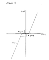
- curve 100 represents the typical torque losses caused by bearing friction introduced by prior designs of dynamometers while the bearings are warming up after start-up.
- Curve 102 represents the torque losses caused by friction of the dynamometer 10 of the present invention after start-up.
- prior art dynamometers must be run for at least 20 to 30 minutes before the bearings become relatively stable, as indicated by curve 100.
- the dynamometer 10 of the present invention requires no such warm-up time.
- the bearing assemblies 60 and 62 are virtually stable almost immediately upon start-up.
- Another significant advantage of the dynamometer 10 of the present invention is its ability to compensate for various loads upon, and significant changes in speed of, the rolls 14 and 16, without the need to factor in predetermined corrections for these variables, as required by prior designs of dynamometers. Since the speed of the bearing rolls 69,69a are adjusted to "track" the speed of the rolls 14,16, regardless of the load imposed on the rolls 14,16, the bearing assemblies 60 and 62, in effect, automatically compensate for changing bearing loads and speed changes which would otherwise change the frictional forces introduced by bearing systems of prior designs of dynamometers. It will be appreciated, however, that conventional compensation algorithms are preferably still incorporated to account for windage resistance to movement of the rolls 14,16 and other losses not caused by friction, and also any residual friction of the bearings 68,68a.
- the encoder assembly 23 includes a quartz crystal oscillator and provides a digital speed signal in the form of a serial bit stream which indicates the speed of the rolls 14,16, and thus the input shaft 32, within a range of about 0.01% of the true speed of the rolls 14,16.
- the encoder assembly 23 has its output coupled to an input 104a of the controller 104.
- the controller 104 which in a preferred embodiment comprises an 80386 microprocessor based computer system, monitors the speed of the rolls 14,16 by monitoring the frequency of the square wave like serial data stream generated by the encoder assembly 23 and supplied via line 23b.
- the controller 104 then calculates a speed value and provides a corresponding output speed signal in the form of a digital serial bit stream to each of the bearing motor drive assemblies 20 and 22 via independent, RS-232 interfaces 106 and 108. Accordingly, independent drive signals in accordance with the speed of the input shaft 32 may be provided to each of the bearing motor drive assemblies 20 and 22 and controllably varied in accordance with the changing frequency of the encoder assembly 23 output signal. This enables each of the bearing motor drive assemblies 20 and 22 to drive their associated inner/outer race members 72a and 72b at variable, predetermined speeds in accordance with the changing speed of the rolls 14,16, and thus the input shaft 32.
- the inner/outer race member 72,72a of each of the bearing assemblies 60 and 62 is driven alternately at speeds slightly slower and faster than the speed of the rolls 14 and 16, and thus the input shaft 32.
- the first bearing motor drive assembly 20 is driving the inner/outer race member 72 of bearing assembly 60 at a speed slightly slower than the rotational speed of the input shaft 32
- the second inner/outer race member 72a of bearing assembly 62 is driven by the second bearing motor drive assembly 22 at a speed slightly greater than the speed of the input shaft 32.
- the speeds at which each of the inner/outer race members 72,72a are driven is "swapped", and the first inner/outer race member 72 is driven at a speed slightly faster than the input shaft 32, while the second inner/outer race member 72a is driven at a speed slightly slower than the input shaft 32.
- the speeds of each of the inner/outer race members 72,72a are further continuously varied in accordance with the changing speed of the input shaft 32 as indicated by encoder assembly 23.
- the characteristic friction vs. speed curve of a bearing includes an ambiguity region around zero speed due to the "stiction" forces which must be overcome to start a bearing moving in either direction. Consequently, since it is impossible to precisely control the speed of the bearings at all times, a control scheme that attempts to match the bearing speed to the ever-changing speed of the input shaft 32 may result in small uncompensated frictional forces from the bearings being introduced into the system. Moreover, it is likely that these frictional forces from the bearings will be cumulative in effect and thus compound the quantity of the error introduced.
- each bearing 68,68a it is desirable to drive each bearing 68,68a at a speed that is purposefully offset from the speed of the input shaft 32 by a predetermined amount which places the bearing speed outside the ambiguity region that exists around zero.
- the frictional forces introduced by the two bearings 68,68a are cancelled out.
- the positive amount of friction that is introduced by the bearing that is driven slightly faster is cancelled out by the corresponding amount of negative friction that is introduced by the bearing that is driven slightly slower.
- a "swap time interval" is selected, as indicated at step 112.
- the swap time interval may vary widely but is preferably within the range of about one to three seconds, and more preferably about one second.
- offsets in miles per hour (mph) are selected for the first bearing motor drive assembly 20 and the second bearing motor drive assembly 22, as indicated at 114.
- the offsets define the speed difference in miles per hour at which the first and second bearing motor drive assemblies of 20 and 22 are to be driven relative to the speed of the input shaft 32.
- the offsets may also range significantly in value but are preferably within the range of about 0.45 to 1.34 m/s (one to three mph), and more preferably about 0.9 m/s (two mph).
- the gains for the first and second bearing motor drive assemblies 20 and 22 are selected, as indicated at step 116.
- the gains each represent a constant dependent upon design factors of each of the motors 20a and 22a, as well as the load considerations which must be simulated by the dynamometer 10.
- ms milliseconds
- the speed of the rolls 14,16 is then obtained from controller 104 ( Figure 8), as shown at step 122, and the speed signals for the first and second bearing motor drive assemblies 20 and 22 are calculated, as indicated as steps 124 and 126, respectively.
- the speed signals calculated at steps 124 and 126 take into account the offsets input in step 114 and the gains selected in step 116, and operate to drive the bearing drive hubs 34 and 42 ( Figure 2) at speeds which differ from the speed of the rolls 14 and 16 by the value of the selected offsets, which as stated are preferably about 0.9 m/s (two mph).
- the calculated speed signal for the first bearing motor drive assembly 20 is then applied to the first bearing motor drive assembly 20, as indicated at step 128.
- the speed signal calculated for the second bearing motor drive assembly 22 is then applied to the second bearing motor drive assembly 22, as indicated at step 130. Accordingly, the first bearing motor drive assembly 20 will drive the bearing drive hub 34, and thus inner/outer race member 72 (shown in Figure 4) at a speed that is approximately 0.9 m/s (two mph) less than the speed of the input shaft 32, and in the same direction as that of the input shaft 32.
- the speed signal for the second bearing motor drive assembly 22 operates to drive the inner/outer race member 70a of bearing assembly 62 ( Figures 3 and 5) at a speed about 0.9 m/s (two mph) faster than that of the input shaft 32, and in the same direction as the input shaft 32.
- the swap interval timer is read to determine if the selected swap time interval has expired, as indicated at step 132. If not, the 50ms timer is checked to determine if it has timed out, as indicated at 134.
- the swap interval timer is reset, as indicated at step 142.
- the 50ms timer is then checked, as indicated at step 144, to determine if it has also timed out. If not, then the calculated speed signal for the second bearing motor drive assembly 22 is applied to the first bearing motor drive assembly 20, as indicated at step 146, while the calculated speed signal for the first bearing motor drive assembly 20 is applied to the second bearing motor drive assembly 22, as indicated by step 148.
- the speed signals are swapped and the first bearing drive hub 34 will be driven at a speed approximately 0.9 m/s (two mph) greater than the speed of the input shaft 32 while the second bearing drive hub 42 will be driven at a speed approximately 0.9 m/s (two mph) less than the input shaft 32.
- the swap interval timer is again checked, as indicated at step 150. If the swap interval timer has not timed out, then the 50ms timer is again checked to determine if it has timed out, as indicated by line 152 and step 144. If the swap interval timer has timed out, then the timer is reset, as indicated at step 154, and the speed signals are again swapped by applying the speed signal calculated for the first bearing motor drive assembly 20 to that assembly and the calculated speed signal for the second bearing motor drive assembly 22 to that assembly, as indicated by line 156 and steps 128 and 130.
- step 144 if the 50ms timer has timed out, then the timer is reset, as indicated at step 158, and the speed of the rolls 14 and 16 (i.e., the input shaft 32 speed) is obtained again, as indicated at step 160.
- the speed signals for the first and second bearing motor drive assemblies 20 and 22 are then recalculated, as indicated at steps 162 and 164, before being applied to the bearing motor drive assemblies 20 and 22, as indicated at steps 146 and 148.
- the speed of the input shaft 32, and thus the rolls 14 and 16 is obtained and the speed signals for the first and second motor drive assemblies 20 and 22 are recalculated, as indicated by steps 160-164 and 122-126. It will be appreciated, however, that some applications, particularly where low speed operation is extensive, may require roll speed updating more frequently than every 50ms.
- the present invention contemplates controlling the speeds of the inner/outer race members 72,72a to minimize frictional losses up to a roll speed of about 26.8-29 m/s (60 mph - 65 mph).
- the speeds of the inner/outer race members 72,72a may be simply maintained, while the frictional losses of the bearings 68,68a due to the difference in roll speed and bearing speed are compensated for by conventional algorithms.
- Yet another advantage of the present invention is the ability of the bearing assemblies 60 and 62 to enable the rolls 14,16 to be driven at speeds above the rated maximum speed of the inner bearings 68,68a.
- each of the inner bearings 68,68a and outer bearings 70,70a are rated to accommodate a maximum roll speed of 44.7 m/s (100 mph)
- the inner/outer race members 72,72a are driven in the same direction of rotation as the input shaft 32 and at a speed equal to that at which the input shaft 32 is driven when the rolls 14,16 are being driven at a speed of about 44.7 m/s (100 mph).
- the input shaft 32 and the inner/outer race members 72,72a will then be traveling at approximately the same speed, but there will be virtually no movement of the inner bearing rolls 69,69a relative to either the input shaft 32 or the inner/outer race members 72,72a.
- the inner bearings 68,68a are essentially stationary.
- the rolls 14,16 may be driven to a rotational speed, in this example, corresponding to about 89.4 m/s (200 mph), before the inner bearings 68,68a are rotating at a speed corresponding to about 44.7 m/s (100 mph) relative to the inner/outer race members 72,72a.
- the rolls 14,16 may be driven to a speed roughly double the maximum speed at which the bearings 68,68a,70,70a are rated for, to thereby enable very high speed testing to be performed without the use of expensive, high speed rated bearings.
Landscapes
- Engineering & Computer Science (AREA)
- General Engineering & Computer Science (AREA)
- Mechanical Engineering (AREA)
- Physics & Mathematics (AREA)
- General Physics & Mathematics (AREA)
- Rolling Contact Bearings (AREA)
Description
Claims (10)
- A chassis dynamometer (10) apparatus comprising:roll means (14,16) for engaging at least one driving wheel (26) of a vehicle during rotational movement of said wheel;first bearing means (68) associated with said roll means for enabling rotational movement of said roll means (14,16) about an axis of rotation relative to a frame portion (56,58) of said dynamometer;second bearing means (70) disposed between said first bearing means (68) and said frame portion (56,58) for enabling rotational movement of said first bearing means (68) relative to said frame portion (56,58); andrace means (72) disposed between said first and second bearing means (68,70);characterised in that:relative to said axis of rotation, said race means (72) is positioned radially outwardly of said first bearing means (68) and radially inwardly of said second bearing means (70), said race means (72) forming an outer race for said first bearing means (68) and an inner race for said second bearing means (70), for enabling said first bearing means (68) to be driven in the same direction of rotation as said roll means (14,16); andthe apparatus further comprises drive means (20,22) for driving said race means (72) in the same direction of rotation as said first bearing means (68) and at a drive speed that is related to the rotational speed of said roll means (14,16) and is selected to cancel frictional forces of said first bearing means (68) opposing rotational movement of said roll means (14,16).
- The apparatus of claim 1, further comprising:
means (23) for sensing the rotational speed of said roll means (14,16) in real-time and generating a speed signal in accordance therewith. - The apparatus of claim 2, wherein said drive means (20,22) comprises a drive motor (20a,22a) responsive to said speed signal.
- The apparatus of claim 3, wherein said drive motor (20a,22a) is arranged to drive said race means (72) at speeds that are alternately slower and faster than the sensed rotational speed of said roll means (14,16).
- The apparatus of claim 2, wherein said roll means (14,16) is journalled to an input shaft (32) and wherein:said first bearing means (68) comprises a pair of radially inner annular bearings (68) each disposed on said input shaft at opposite ends (32a,32b) of said input shaft;said second bearing means (70) comprises a pair of radially outer annular bearings (70), each one of said outer annular bearings (70) being disposed coaxially in-between an associated one of said inner annular bearings (68) and an associated frame portion (56,58) of said apparatus;said race means (72) comprises a pair of radially inner/outer race members (72a,72b), each said inner/outer race member being disposed in-between a respective one of said inner and outer annular bearings (68,70) and each active as a radially outer race for its respective inner annular bearing (68) and a radially inner race for its respective outer annular bearing (70); andwherein said drive means (20,22) comprises a pair of drive motors (20a,22a) responsive to said speed signal and coupled to said inner/outer race members (72a,72b) for driving said inner/outer race members in the same direction of rotation as said roll means (14,16) and at variable speeds in accordance with the rotational speed of said roll means.
- The apparatus of claim 5, wherein said drive motors (20a,22a) are arranged to drive said inner/outer race members (72a,72b) at speeds alternately faster and slower than the rotational speed of said inner annular bearings (68).
- The apparatus of claim 5, wherein said drive motors (20a,22a) are each coupled independently to one of said pair of inner/outer race members (72a,72b) for driving each of said inner/outer race members independently of each other in the same direction of rotation as said roll means (14,16).
- The apparatus of claim 7, wherein said drive motors (20a,22a) are arranged to alternately drive said inner/outer race members (72a,72b) at rotational speeds faster and slower than the rotational speeds of their respective inner annular bearings (68) such that, when one of said inner/outer race members (72a,72b) is being driven at a slower speed than its respective inner annular bearing (68), the other inner/outer race member is being driven at a rotational speed greater than the speed of its associated inner annular bearing, and when said one inner/outer race member is being driven at a rotational speed slower than the rotational speed of its respective inner annular bearing, said other inner/outer race member is driven at a speed greater than the rotational speed of its associated inner annular bearing.
- A method for cancelling frictional forces, in a chassis dynamometer (10), which oppose rotational movement of a roller (14) of the dynamometer as the roller is driven by the driving wheels (26) of a vehicle under test, said method comprising:providing a power exchange device (18) having an input shaft (32) fixedly coupled to said roller (14);providing a radially inner annular roller bearing (68) coaxially disposed over said input shaft (32);providing a radially outer annular roller bearing (70) coaxially disposed and laterally aligned with said inner annular roller bearing (68) on said input shaft (32), said outer annular roller bearing being supported by a frame portion (56) of the dynamometer;providing an inner/outer race member (72) interposed radially between said inner and outer annular roller bearings (68,70) and forming a radially outer race of said inner annular bearing (68) and a radially inner race of said outer annular bearing (70);driving said inner/outer race member (72) at a variable rotational speed related to the rotational speed of said input shaft (32); andcontrolling the speed at which said inner/outer race member (72) is driven so as to cancel said frictional forces.
- The method of claim 9, further comprising the step of driving the inner/outer race member (72) alternately at rotational speeds that are lesser and greater than the rotational speed of said input shaft (32) and switching between said faster and slower rotational speeds in accordance with a predetermined time interval.
Applications Claiming Priority (2)
| Application Number | Priority Date | Filing Date | Title |
|---|---|---|---|
| US893678 | 1986-08-06 | ||
| US07/893,678 US5311770A (en) | 1992-06-05 | 1992-06-05 | Frictionless bearing chassis dynamometer |
Publications (3)
| Publication Number | Publication Date |
|---|---|
| EP0573302A2 EP0573302A2 (en) | 1993-12-08 |
| EP0573302A3 EP0573302A3 (en) | 1995-02-08 |
| EP0573302B1 true EP0573302B1 (en) | 1998-08-19 |
Family
ID=25401906
Family Applications (1)
| Application Number | Title | Priority Date | Filing Date |
|---|---|---|---|
| EP93304356A Expired - Lifetime EP0573302B1 (en) | 1992-06-05 | 1993-06-04 | Frictionless bearing chassis dynamometer |
Country Status (4)
| Country | Link |
|---|---|
| US (1) | US5311770A (en) |
| EP (1) | EP0573302B1 (en) |
| JP (1) | JP2651783B2 (en) |
| DE (1) | DE69320411T2 (en) |
Cited By (1)
| Publication number | Priority date | Publication date | Assignee | Title |
|---|---|---|---|---|
| CN101762350B (en) * | 2010-01-19 | 2011-08-31 | 中国汽车技术研究中心 | Centrally-mounted motorcar chassis electricity dynamometer |
Families Citing this family (18)
| Publication number | Priority date | Publication date | Assignee | Title |
|---|---|---|---|---|
| WO1995031705A1 (en) * | 1994-05-16 | 1995-11-23 | Real Time Instruments, Inc. | Suspended single roll dynamometer |
| DE19730851B4 (en) * | 1996-08-01 | 2006-07-06 | Horiba Automotive Test Systems Gmbh | Method of simulating inertial forces using a dynamometer |
| DE19647513A1 (en) * | 1996-11-16 | 1998-05-20 | Schenck Komeg Gmbh | Rotary flywheel disc accommodation for automobile test stand |
| DE19900620A1 (en) * | 1999-01-11 | 2000-07-13 | Maha Gmbh & Co Kg | Vehicle test bed has drum control stator housings in moving supports and bearings with constant pressure flow oil pockets |
| US6439037B1 (en) * | 2000-06-29 | 2002-08-27 | D'angelo Severino | Dynamometer having improved sensing configuration |
| US6561013B1 (en) | 2001-10-30 | 2003-05-13 | Burke E. Porter Machinery Company | Vehicle testing assembly |
| AU2003273452B2 (en) * | 2002-08-01 | 2008-06-12 | Bertin Technologies S.A | Device for fast vibration of tubes containing samples |
| DE10325276A1 (en) * | 2003-06-03 | 2004-12-23 | Schenck Pegasus Gmbh | Chassis dynamometer |
| US20070033994A1 (en) * | 2005-08-10 | 2007-02-15 | D Angelo Severino | Dynamometer with flexible closed loop torque transmitting element |
| JP4600934B2 (en) * | 2006-04-28 | 2010-12-22 | 株式会社エー・アンド・デイ | Chassis dynamometer |
| JP2007333406A (en) * | 2006-06-12 | 2007-12-27 | Toyo Electric Mfg Co Ltd | Chassis dynamometer |
| US7377153B2 (en) * | 2006-07-11 | 2008-05-27 | Bergeron Robert M | Dynamometer frame |
| DE102008022089B4 (en) * | 2008-05-05 | 2010-03-18 | Horiba Automotive Test Systems Gmbh | Test bench with pedestal bearing |
| KR101629528B1 (en) * | 2008-09-08 | 2016-06-21 | 버크 이. 포터 머쉬너리 컴퍼니 | Vehicle testing assembly |
| SE535471C2 (en) * | 2010-10-18 | 2012-08-21 | Method and apparatus for dynamometer testing of a motor vehicle | |
| DE102013202387A1 (en) * | 2013-02-14 | 2014-08-14 | Zf Friedrichshafen Ag | Wheel drive assembly for fork-lift truck, has first and second taper roller bearings whose rollers are inclined in same direction, where second taper roller bearing is partially arranged within first taper roller bearing |
| DE102014009478A1 (en) | 2014-06-30 | 2015-12-31 | Ba Assembly & Turnkey Systems Gmbh | Manipulator with a manipulator arm |
| CN113029409B (en) * | 2021-02-22 | 2022-03-01 | 江苏徐工工程机械研究院有限公司 | Motor direct drive hubs for heavy duty chassis dynamometers |
Family Cites Families (7)
| Publication number | Priority date | Publication date | Assignee | Title |
|---|---|---|---|---|
| SU626468A1 (en) * | 1975-03-24 | 1978-09-30 | Luzin Mikhail | Ac electric motor |
| US4077255A (en) * | 1975-10-24 | 1978-03-07 | Hitachi, Ltd. | Roller type chassis dynamometer |
| DE2617553A1 (en) * | 1976-04-22 | 1977-11-03 | Heinrich Kunel | Multistage rolling bearings with several concentric races - use several rows of rollers or balls to permit increased speed of shafts |
| FR2595779A1 (en) * | 1986-03-14 | 1987-09-18 | Valeo | DAMPER FLYWHEEL FOR TRANSMISSION, IN PARTICULAR FOR A MOTOR VEHICLE |
| JPH028512A (en) * | 1988-06-27 | 1990-01-12 | Nippon Denso Co Ltd | Triple race bearing |
| US5154076A (en) * | 1991-02-08 | 1992-10-13 | Clayton Industries | Dynamometer for simulating the inertial and road load forces encountered by motor vehicles |
| DE4111994A1 (en) * | 1991-04-12 | 1992-10-15 | Herter Tamara | Ball- or roller-bearing - has intermediate rollers between adjacent balls or rollers of nylon, plastic or hard rubber |
-
1992
- 1992-06-05 US US07/893,678 patent/US5311770A/en not_active Expired - Lifetime
-
1993
- 1993-06-04 DE DE69320411T patent/DE69320411T2/en not_active Expired - Fee Related
- 1993-06-04 EP EP93304356A patent/EP0573302B1/en not_active Expired - Lifetime
- 1993-06-07 JP JP5164189A patent/JP2651783B2/en not_active Expired - Fee Related
Cited By (1)
| Publication number | Priority date | Publication date | Assignee | Title |
|---|---|---|---|---|
| CN101762350B (en) * | 2010-01-19 | 2011-08-31 | 中国汽车技术研究中心 | Centrally-mounted motorcar chassis electricity dynamometer |
Also Published As
| Publication number | Publication date |
|---|---|
| JP2651783B2 (en) | 1997-09-10 |
| JPH0650850A (en) | 1994-02-25 |
| DE69320411D1 (en) | 1998-09-24 |
| DE69320411T2 (en) | 1998-12-24 |
| EP0573302A2 (en) | 1993-12-08 |
| US5311770A (en) | 1994-05-17 |
| EP0573302A3 (en) | 1995-02-08 |
Similar Documents
| Publication | Publication Date | Title |
|---|---|---|
| US5311770A (en) | Frictionless bearing chassis dynamometer | |
| US4771845A (en) | Motor-driven power steering system and method of controlling same | |
| JP3338214B2 (en) | Dynamometer | |
| EP0507631A1 (en) | Method and apparatus for testing two or four wheel drive vehicles under simulated road conditions | |
| KR19990008219A (en) | Chassis Dynamometer using both moving roller assemblies during vehicle alignment | |
| JP4321124B2 (en) | Electric inertia control system for power measurement system | |
| EP2225542A2 (en) | Dynamometer | |
| US5375460A (en) | Method and apparatus for testing motor vehicles under simulated road conditions | |
| US5641904A (en) | Method and apparatus for detecting drive line system imbalance | |
| WO2001053791A1 (en) | Portable roller dynamometer and vehicle testing method | |
| EP3749943B1 (en) | Method and apparatus for dynamometer testing of a motor vehicle | |
| US4848142A (en) | Motor vehicle performance test apparatus | |
| EP0772766B1 (en) | Suspended single roll dynamometer | |
| US6960024B2 (en) | Center bearing assembly including a support member containing a rheological fluid | |
| JP2003513227A (en) | Portable roller dynamometer and vehicle test method | |
| US5154077A (en) | Chassis dynamometer | |
| JPH0276647A (en) | Bearing installing method | |
| JP4807547B2 (en) | Toroidal continuously variable transmission | |
| JP2023122910A (en) | Dynamic torque measuring device and dynamic torque measuring method | |
| JPH0874844A (en) | Pre-pressure estimation method and device for bearing device for vehicular shaft | |
| McMahon et al. | Results from 10 years of reaction/momentum wheel life testing | |
| JPWO2001057417A1 (en) | Toroidal type continuously variable transmission | |
| JP2002283880A (en) | Shift abnormality countermeasure device for vehicles with continuously variable transmission | |
| CN216433521U (en) | Transfer case no-load test transmission connecting device | |
| JPH0125414B2 (en) |
Legal Events
| Date | Code | Title | Description |
|---|---|---|---|
| PUAI | Public reference made under article 153(3) epc to a published international application that has entered the european phase |
Free format text: ORIGINAL CODE: 0009012 |
|
| AK | Designated contracting states |
Kind code of ref document: A2 Designated state(s): DE FR GB |
|
| PUAL | Search report despatched |
Free format text: ORIGINAL CODE: 0009013 |
|
| AK | Designated contracting states |
Kind code of ref document: A3 Designated state(s): DE FR GB |
|
| 17P | Request for examination filed |
Effective date: 19950626 |
|
| 17Q | First examination report despatched |
Effective date: 19960808 |
|
| GRAG | Despatch of communication of intention to grant |
Free format text: ORIGINAL CODE: EPIDOS AGRA |
|
| GRAG | Despatch of communication of intention to grant |
Free format text: ORIGINAL CODE: EPIDOS AGRA |
|
| GRAG | Despatch of communication of intention to grant |
Free format text: ORIGINAL CODE: EPIDOS AGRA |
|
| GRAH | Despatch of communication of intention to grant a patent |
Free format text: ORIGINAL CODE: EPIDOS IGRA |
|
| GRAH | Despatch of communication of intention to grant a patent |
Free format text: ORIGINAL CODE: EPIDOS IGRA |
|
| GRAA | (expected) grant |
Free format text: ORIGINAL CODE: 0009210 |
|
| AK | Designated contracting states |
Kind code of ref document: B1 Designated state(s): DE FR GB |
|
| PG25 | Lapsed in a contracting state [announced via postgrant information from national office to epo] |
Ref country code: FR Free format text: THE PATENT HAS BEEN ANNULLED BY A DECISION OF A NATIONAL AUTHORITY Effective date: 19980819 |
|
| REF | Corresponds to: |
Ref document number: 69320411 Country of ref document: DE Date of ref document: 19980924 |
|
| ET | Fr: translation filed | ||
| PG25 | Lapsed in a contracting state [announced via postgrant information from national office to epo] |
Ref country code: GB Free format text: LAPSE BECAUSE OF NON-PAYMENT OF DUE FEES Effective date: 19990604 |
|
| PLBE | No opposition filed within time limit |
Free format text: ORIGINAL CODE: 0009261 |
|
| STAA | Information on the status of an ep patent application or granted ep patent |
Free format text: STATUS: NO OPPOSITION FILED WITHIN TIME LIMIT |
|
| 26N | No opposition filed | ||
| GBPC | Gb: european patent ceased through non-payment of renewal fee |
Effective date: 19990604 |
|
| PG25 | Lapsed in a contracting state [announced via postgrant information from national office to epo] |
Ref country code: DE Free format text: LAPSE BECAUSE OF NON-PAYMENT OF DUE FEES Effective date: 20000503 |
|
| REG | Reference to a national code |
Ref country code: FR Ref legal event code: ST |