EP0573119B1 - Roller conveyor - Google Patents
Roller conveyor Download PDFInfo
- Publication number
- EP0573119B1 EP0573119B1 EP93201559A EP93201559A EP0573119B1 EP 0573119 B1 EP0573119 B1 EP 0573119B1 EP 93201559 A EP93201559 A EP 93201559A EP 93201559 A EP93201559 A EP 93201559A EP 0573119 B1 EP0573119 B1 EP 0573119B1
- Authority
- EP
- European Patent Office
- Prior art keywords
- rollers
- carrying
- carrying rollers
- axle
- driving belt
- Prior art date
- Legal status (The legal status is an assumption and is not a legal conclusion. Google has not performed a legal analysis and makes no representation as to the accuracy of the status listed.)
- Expired - Lifetime
Links
Images

Classifications
-
- B—PERFORMING OPERATIONS; TRANSPORTING
- B65—CONVEYING; PACKING; STORING; HANDLING THIN OR FILAMENTARY MATERIAL
- B65G—TRANSPORT OR STORAGE DEVICES, e.g. CONVEYORS FOR LOADING OR TIPPING, SHOP CONVEYOR SYSTEMS OR PNEUMATIC TUBE CONVEYORS
- B65G47/00—Article or material-handling devices associated with conveyors; Methods employing such devices
- B65G47/22—Devices influencing the relative position or the attitude of articles during transit by conveyors
- B65G47/26—Devices influencing the relative position or the attitude of articles during transit by conveyors arranging the articles, e.g. varying spacing between individual articles
-
- B—PERFORMING OPERATIONS; TRANSPORTING
- B65—CONVEYING; PACKING; STORING; HANDLING THIN OR FILAMENTARY MATERIAL
- B65G—TRANSPORT OR STORAGE DEVICES, e.g. CONVEYORS FOR LOADING OR TIPPING, SHOP CONVEYOR SYSTEMS OR PNEUMATIC TUBE CONVEYORS
- B65G13/00—Roller-ways
- B65G13/02—Roller-ways having driven rollers
- B65G13/06—Roller driving means
- B65G13/07—Roller driving means having endless driving elements
Definitions
- the invention relates to a conveyor of the type, provided with a series of carrying rollers which are rotatably mounted in a frame about parallel axes, and with a driving belt passing under these carrying rollers, said belt being pressed into friction contact with the carrying rollers by means of pressure rollers, which are mounted on the free ends of carrying arms which extend substantially parallel to the carrying rollers and are swingably mounted for adjustment through a small angle.
- Such a conveyor is disclosed in US-A-4.091.916.
- the pressure rollers are positioned directly below the carrying rollers so that the places of contact between the driving belt and the carrying rollers coincide with those between the driving belt and the underlying pressure rollers.
- the driving belt in the well-known conveyor is of a circular cross-sectional form so that in reality there is only a point contact between the carrying rollers and the driving belt. Consequently the transfer of power through the driving belt to the carrying rollers is rather limited.
- the above mentioned drawback is removed in a simple and effective manner, in that the pressure rollers engage the driving belt at locations between adjacent carrying rollers, whereas the circumferential surface of said pressure rollers is slightly convex in shape.
- the pressure rollers By having the pressure rollers engage the driving belt at locations between the carrying rollers, the contact between the driving belt and each of the carrying rollers will, as seen in the direction of rotation, take place along an arc of a circle. Furthermore the convex shape of the pressure rollers enables to use a flat and wider driving belt and to press this belt to the carrying rollers with a larger or smaller contact pressure. For, when such a pressure roller is swung from a horizontal central position upwardly through an angle in the order of e.g. 1°, an increase in contact pressure between the driving belt and the ("higher" portions of the excentric) carrying rollers will take place.
- the convex shape of the pressure rollers causes the driving belt to shift across the pressure roller surface in a direction turned away from the swinging point and to adjust itself according to the shifted highest point of the pressure roller surface. This secures the driving belt to be kept in contact with the carrying rollers with an even pressure.
- roller conveyors in which pressure rollers are pressed - at intermediate locations - against a driving belt passing under the carrying rollers, are well-known per se.
- the pressure rollers are mounted for vertical adjustment, the vertical adjustment taking place by turning an adjustment screw at both ends of each pressure roller.
- the conveyor has a frame, which is mainly formed by two parallel longitudinal beams, one of which being shown in the drawing and indicated at 1.
- a series of carrying rollers 2 is mounted between the two frame beams for rotation about parallel axes.
- the way of supporting of the carrying rollers 2 corresponds with that of the well-known conveyors of the type under consideration and will therefore not be described in further detail.
- For the spacing between the successive carrying rollers 2 (which may have a diameter in the order of 50 mm) reference is made to fig. 2.
- This drive belt designates a driving belt which passes under the carrying rollers 2 at one side of the conveyor.
- This drive belt may e.g. be constituted by the upper run of a driven endless belt which is guided, at the ends of the conveyor over guide rollers (not shown in the drawing) and which is kept in a tensioned state by tensioning rollers (neither shown) which are positioned at the lower run of the endless belt.
- the driving belt 3 is supported by a series of pressure rollers 4, the rotating axes of which are each positioned substantially directly under the space between two successive carrying rollers 2 (vide fig. 2).
- the number of pressure rollers 4 is e.g. half the number of carrying rollers 2, so that alternately a pressure roller and no pressure roller respectively is positioned under the successive spaces between the carrying rollers.
- the width of the pressure rollers 4 is a fraction of the length of the carrying rollers 2 and is slightly larger than the width of the driving belt 3.
- the pressure rollers 4 are rotatably mounted on the free end portion of a stationary supporting axle 5 which is extended towards the frame beam 1; the pressure rollers 4 are slightly convex in shape.
- the supporting axles 5 are each supported by a substantially L-shaped support body 6, which has its vertical flange 6a hooked about a support strip 7 fixed to the frame beam 1 and has the free end of its horizontal flange 6b leaning against the innerside of the vertical web 1a of the frame beam 1 and fixed to the latter by means of fastening screws (not shown) which extend through lug-shaped projections 19 of the horizontal flange 6b (vide fig. 2).
- the hollow shaped horizontal flange 6b, supporting the supporting axle 5, is closed at its free end by a thin endwall 8, a circular opening 8a being provided in said wall to support the respective end of the supporting axle 5 with a close fit.
- the small fitness of the endwall 8 allows a certain universal swinging movement of the supporting axle 5 around the center of the opening in said endwall.
- a vertical slot 9 is provided, the width of which corresponds with the diameter of the supporting axle 5. Due to this slot the universal swinging movement allowed by the opening in the endwall 8 is limited to an up and down swinging movement in the vertical plane.
- the vertical flange 6a of the L-shaped body 6 comprises a tubular portion 10 the free end of which is located substantially in the plane of the upper flange 1b of the frame beam 1. At a certain distance from the horizontal flange 6b the tubular portion merges into a widened chamber 11, containing a block 12 of rubber or similar resilient material which is locked in place between the supporting axle 5 and the lower end of the tubular portion 10.
- An adjusting screw 14 extends - with clearance - through the bore 13 of the tubular portion 10 and has its head 15 bearing on the upper end face of the vertical L-flange with the intermediary of a washer 16, whereas the threaded shaft portion 17 of the screw extends through a correspondingly threaded radial bore 18 of the supporting axle 5.
- the adjusting screw 14 By turning the adjusting screw 14 to extend further or less downwardly through the radial bore 18 of the supporting axle 5, the latter may be swung through a slight angle upwardly or downwardly about the centre of the bearing opening 8a.
- the supporting axle 5 is taking a horizontal central position, parallel to the rotating axes of the supporting rollers 2.
- the driving belt 3 is positioned in the central portion of the convex supporting surface of the pressure roller 4 and consequently also takes a horizontal position as seen in the transverse direction.
- the driving belt 3 is shown out of contact with the adjacent supporting rollers 2.
- This case may be illustrative for a conveyor having excentrically journalled supporting rollers (e.g. having an excentricity in the order of 1 mm) at a moment, at which the surface line with the largest radial distance to the supporting roller axis is positioned at the upper side of the roller.
- excentrically journalled supporting rollers e.g. having an excentricity in the order of 1 mm
- At regularly spaced intervals e.g. with a spacing of 4-5 m
- thickenings such as the pad 20 in fig. 2 are provided on the driving belt 3.
- the shown position may also be considered representative of an embodiment with centrically journalled rollers, in which case the respective pressure roller is shown in an inoperative position, caused by a downwardly directed swinging movement.
- the pressure roller mounting on a swingable supporting axle is also applicable in those cases, in which it must be possible to put a certain section of an accumulating conveyor out of operation, e.g. pneumatically.
Abstract
Description
- The invention relates to a conveyor of the type, provided with a series of carrying rollers which are rotatably mounted in a frame about parallel axes, and with a driving belt passing under these carrying rollers, said belt being pressed into friction contact with the carrying rollers by means of pressure rollers, which are mounted on the free ends of carrying arms which extend substantially parallel to the carrying rollers and are swingably mounted for adjustment through a small angle.
- Such a conveyor is disclosed in US-A-4.091.916. With this well-known roller conveyor the pressure rollers are positioned directly below the carrying rollers so that the places of contact between the driving belt and the carrying rollers coincide with those between the driving belt and the underlying pressure rollers. This means that there is only a limited area of contact between the carrying rollers and the driving belt, said contact being in principle no more than the contact along a line parallel to the roller axis. Furthermore, the driving belt in the well-known conveyor is of a circular cross-sectional form so that in reality there is only a point contact between the carrying rollers and the driving belt. Consequently the transfer of power through the driving belt to the carrying rollers is rather limited. This is particularly disadvantageous in a special embodiment of such a conveyor, in which use is made of excentrically mounted carrying rollers, which are - as a consequence of the excentric mounting - contacted by the underlying driving belt during only a portion of each revolution. Due to the inertia of the carrying rollers the latter will keep rotating also during the interval in which there is no contact with the driving belt. Assuming a load travelling on such rotating carrying rollers is stopped (for example by a load in front of it) the respective carrying rollers will come to a standstill at the time the contact with the driving belt is interrupted. This causes the load to keep stationary, up to the moment, at which the carrying rollers are activated again by means of pads or "dogs" which are provided on the driving belt at longitudinally spaced intervals and are bridging the excentricity of the carrying rollers. Particularly with such a type of conveyor, called "accumulating roller conveyor", it is important that the pressure rollers can be adjusted to the correct pressure (which may e.g. be dependent of the size and the weight of the loads to be conveyed).
- In accordance with the present invention the above mentioned drawback is removed in a simple and effective manner, in that the pressure rollers engage the driving belt at locations between adjacent carrying rollers, whereas the circumferential surface of said pressure rollers is slightly convex in shape.
- By having the pressure rollers engage the driving belt at locations between the carrying rollers, the contact between the driving belt and each of the carrying rollers will, as seen in the direction of rotation, take place along an arc of a circle. Furthermore the convex shape of the pressure rollers enables to use a flat and wider driving belt and to press this belt to the carrying rollers with a larger or smaller contact pressure. For, when such a pressure roller is swung from a horizontal central position upwardly through an angle in the order of e.g. 1°, an increase in contact pressure between the driving belt and the ("higher" portions of the excentric) carrying rollers will take place. The convex shape of the pressure rollers causes the driving belt to shift across the pressure roller surface in a direction turned away from the swinging point and to adjust itself according to the shifted highest point of the pressure roller surface. This secures the driving belt to be kept in contact with the carrying rollers with an even pressure.
- Conversely a downward swinging adjustment will cause the driving belt to shift across the pressure roller surface in a direction towards the swinging point.
- It is to be noted that roller conveyors, in which pressure rollers are pressed - at intermediate locations - against a driving belt passing under the carrying rollers, are well-known per se. In these well-known conveyors the pressure rollers are mounted for vertical adjustment, the vertical adjustment taking place by turning an adjustment screw at both ends of each pressure roller. Taking into consideration, that in most cases adjustments in the order of millimeters and fractions of millimeters are involved, it will be understood, that such a manner of making adjustments will lead to inaccuracies in the overall adjustment and that it will be also very time consuming in case of rather lengthy conveyors having many pressure rollers.
- As remarked hereinabove with respect to the well-known embodiments, a rather small height-adjustment range and consequently - in case of the embodiment according to the present invention - a rather small adjustment angle (which in practice will be e.g. between 1° and 2°), is involved. Therefore a slight degree of convexness will be enough to make sure that within the angular adjustment range the highest point of the pressure roller surface will be kept at a sufficient distance (in the order of half of the driving belt width) from the highest positioned end of the pressure roller.
- It is further to be noted that it is commonly known to urge a belt that is guided over rollers or sheaves to follow the right track by giving the rollers or sheaves a slightly convex shape.
- Further characteristics of the invention will be hereinafter further explained by way of example with reference to the drawing.
- Fig. 1 shows a cross-section through a side portion of a conveyor according to the invention, with the pressure roller in a (horizontal) central position;
- fig. 2 is a cross-sectional view along the line II-II in fig. 1;
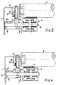
- fig. 3 shows a cross-sectional view similar to that of fig. 1, but now with the pressure roller in the uppermost position and
- fig. 4 shows a cross-sectional view similar to that of fig. 1, but now with the pressure roller in the lowermost position.
- In the example shown in the drawing the conveyor has a frame, which is mainly formed by two parallel longitudinal beams, one of which being shown in the drawing and indicated at 1. A series of
carrying rollers 2 is mounted between the two frame beams for rotation about parallel axes. The way of supporting of thecarrying rollers 2 corresponds with that of the well-known conveyors of the type under consideration and will therefore not be described in further detail. For the spacing between the successive carrying rollers 2 (which may have a diameter in the order of 50 mm) reference is made to fig. 2. - 3 designates a driving belt which passes under the
carrying rollers 2 at one side of the conveyor. This drive belt may e.g. be constituted by the upper run of a driven endless belt which is guided, at the ends of the conveyor over guide rollers (not shown in the drawing) and which is kept in a tensioned state by tensioning rollers (neither shown) which are positioned at the lower run of the endless belt. - The
driving belt 3 is supported by a series ofpressure rollers 4, the rotating axes of which are each positioned substantially directly under the space between two successive carrying rollers 2 (vide fig. 2). The number ofpressure rollers 4 is e.g. half the number ofcarrying rollers 2, so that alternately a pressure roller and no pressure roller respectively is positioned under the successive spaces between the carrying rollers. - The width of the
pressure rollers 4 is a fraction of the length of thecarrying rollers 2 and is slightly larger than the width of thedriving belt 3. Thepressure rollers 4 are rotatably mounted on the free end portion of a stationary supportingaxle 5 which is extended towards theframe beam 1; thepressure rollers 4 are slightly convex in shape. - The supporting
axles 5 are each supported by a substantially L-shaped support body 6, which has its vertical flange 6a hooked about a support strip 7 fixed to theframe beam 1 and has the free end of its horizontal flange 6b leaning against the innerside of the vertical web 1a of theframe beam 1 and fixed to the latter by means of fastening screws (not shown) which extend through lug-shaped projections 19 of the horizontal flange 6b (vide fig. 2). - The hollow shaped horizontal flange 6b, supporting the supporting
axle 5, is closed at its free end by a thin endwall 8, a circular opening 8a being provided in said wall to support the respective end of the supportingaxle 5 with a close fit. The small fitness of the endwall 8 allows a certain universal swinging movement of the supportingaxle 5 around the center of the opening in said endwall. At the opposite end of the horizontal flange 6b, at the angular point of the L, avertical slot 9 is provided, the width of which corresponds with the diameter of the supportingaxle 5. Due to this slot the universal swinging movement allowed by the opening in the endwall 8 is limited to an up and down swinging movement in the vertical plane. The vertical flange 6a of the L-shaped body 6 comprises atubular portion 10 the free end of which is located substantially in the plane of the upper flange 1b of theframe beam 1. At a certain distance from the horizontal flange 6b the tubular portion merges into a widenedchamber 11, containing ablock 12 of rubber or similar resilient material which is locked in place between the supportingaxle 5 and the lower end of thetubular portion 10. - An adjusting
screw 14 extends - with clearance - through thebore 13 of thetubular portion 10 and has itshead 15 bearing on the upper end face of the vertical L-flange with the intermediary of awasher 16, whereas the threadedshaft portion 17 of the screw extends through a correspondingly threaded radial bore 18 of the supportingaxle 5. - By turning the adjusting
screw 14 to extend further or less downwardly through the radial bore 18 of the supportingaxle 5, the latter may be swung through a slight angle upwardly or downwardly about the centre of the bearing opening 8a. - In fig. 1 the supporting
axle 5 is taking a horizontal central position, parallel to the rotating axes of the supportingrollers 2. Thedriving belt 3 is positioned in the central portion of the convex supporting surface of thepressure roller 4 and consequently also takes a horizontal position as seen in the transverse direction. - By turning the adjustment screw - starting from the central position in fig. 1 - in the home direction the screw will be threaded further downwardly through the radial bore 18 in the supporting axle, due to which the supporting axle is slightly swung upwardly and thereby compress the block 12 (vide fig. 3). As a result of this the driving belt at the location of the
respective pressure roller 4 will be slightly displaced upwardly as compared with the position in fig. 1. Simultaneously thedriving belt 3 will be slightly shift to the right and so keep its horizontal transverse position due to the convex shape of thepressure roller 4. Consequently thedriving belt 3 will exert an increased bu (in the transverse direction) evenly distributed pressure onto the adjacent supporting rollers. - If, however, the
adjustment screw 14 is turned anti-clockwise so that it is threaded slightly upwardly from the radial bore 18 in the supportingaxle 5, therubber block 12 will be permitted to relax and cause the supportingaxle 5 to swing downwardly through a slight angle. This leads to a position as shown in fig. 4, in which the driving belt is shifted across the convex supporting surface of thepressure roller 4 to the left, while it has kept its horizontal transverse position parallel to the axes of the supportingrollers 2. - In fig. 4 the
driving belt 3 is shown out of contact with the adjacent supportingrollers 2. This case may be illustrative for a conveyor having excentrically journalled supporting rollers (e.g. having an excentricity in the order of 1 mm) at a moment, at which the surface line with the largest radial distance to the supporting roller axis is positioned at the upper side of the roller. At regularly spaced intervals (e.g. with a spacing of 4-5 m) thickenings, such as thepad 20 in fig. 2, are provided on thedriving belt 3. - The shown position may also be considered representative of an embodiment with centrically journalled rollers, in which case the respective pressure roller is shown in an inoperative position, caused by a downwardly directed swinging movement.
- The pressure roller mounting on a swingable supporting axle is also applicable in those cases, in which it must be possible to put a certain section of an accumulating conveyor out of operation, e.g. pneumatically.
Claims (4)
- A conveyor of the type, provided with a series of carrying rollers (2) which are rotatably mounted in a frame (1) about parallel axes, and with a driving belt (3) passing under these carrying rollers (2), said belt (3) being pressed into friction contact with the carrying rollers (2) by means of pressure rollers (4), which are mounted on the free ends of carrying arms (5) which extend substantially parallel to the carrying rollers (2) and are swingably mounted for adjustment through a small angle, characterized in that the pressure rollers (4) engage the driving belt (3) at locations between adjacent carrying rollers (2), and that the circumferential surface of said pressure rollers (4) is slightly convex in shape.
- A conveyor according to claim 1, characterized in that the carrying arm (5) is formed by a stationary supporting axle which is extended to one side, said axle (5) engaging - at its end turned away from the respective pressure roller (4) - into a seat (8a) in the frame that permits a swinging movement in a vertical plane, whereas a connecting member (14) of an adjustable length is provided, that engages the supporting axle (5) at a place between the pressure roller (4) and the supported axle end and connects said place to a fixed point of the frame positioned directly thereunder or above.
- A conveyor according to claim 2, characterized in that the supporting axle (5) is accommodated in the hollow space of the horizontal flange (6b) of a substantially L-shaped support body (6), that is removably mounted in a longitudinal beam (1) of the conveyor frame, said flange (6b) being at its free end turned away from the pressure roller (4) that leans against the web (1a) of said frame beam, closed by a thin end wall (8) through which the supporting axle extends with a close fit, whereas the supporting axle (5) is extending through a vertical guiding slot (9) provided at the angular point of the L.
- A conveyor according to claims 2 and 3, characterized in that said connecting member (14) of adjustable length is formed by an adjusting screw (14), extending through the tubular vertical flange (6a) of the L-shaped support body (6), the lower portion of said vertical flange (6a) being formed by a piece (12) of rubber or similar resilient material resting on the support axle (5), the lower, threaded end (17) of said adjusting screw (14) extending through a correspondingly threaded radial bore (18) in the said axle (5), whereas the screw head (15) is bearing on the upper end face of the vertical flange (6a) of the L-shaped body (6).
Applications Claiming Priority (2)
| Application Number | Priority Date | Filing Date | Title |
|---|---|---|---|
| NL9200958 | 1992-05-31 | ||
| NL9200958A NL9200958A (en) | 1992-05-31 | 1992-05-31 | ROLLER TRANSPORTOR. |
Publications (2)
| Publication Number | Publication Date |
|---|---|
| EP0573119A1 EP0573119A1 (en) | 1993-12-08 |
| EP0573119B1 true EP0573119B1 (en) | 1996-10-30 |
Family
ID=19860865
Family Applications (1)
| Application Number | Title | Priority Date | Filing Date |
|---|---|---|---|
| EP93201559A Expired - Lifetime EP0573119B1 (en) | 1992-05-31 | 1993-06-01 | Roller conveyor |
Country Status (6)
| Country | Link |
|---|---|
| EP (1) | EP0573119B1 (en) |
| AT (1) | ATE144750T1 (en) |
| DE (1) | DE69305691T2 (en) |
| DK (1) | DK0573119T3 (en) |
| ES (1) | ES2096192T3 (en) |
| NL (1) | NL9200958A (en) |
Family Cites Families (5)
| Publication number | Priority date | Publication date | Assignee | Title |
|---|---|---|---|---|
| US2001773A (en) * | 1931-04-08 | 1935-05-21 | Lamson Co | Conveyer curve |
| US3176828A (en) * | 1962-11-06 | 1965-04-06 | Alvey Ferguson Co | Accumulating conveyor having skewable rollers |
| US4103769A (en) * | 1976-07-06 | 1978-08-01 | Stone Conveyor, Inc. (Entire) | Live roller conveyor |
| US4091916A (en) * | 1976-10-08 | 1978-05-30 | W & H Conveyor Systems, Inc. | Apparatus for driving individual rollers of a power conveyer |
| GB2204294B (en) * | 1987-04-23 | 1991-01-09 | Daifuku Kk | Roller conveyor |
-
1992
- 1992-05-31 NL NL9200958A patent/NL9200958A/en not_active Application Discontinuation
-
1993
- 1993-06-01 AT AT93201559T patent/ATE144750T1/en not_active IP Right Cessation
- 1993-06-01 ES ES93201559T patent/ES2096192T3/en not_active Expired - Lifetime
- 1993-06-01 DE DE69305691T patent/DE69305691T2/en not_active Expired - Fee Related
- 1993-06-01 DK DK93201559.7T patent/DK0573119T3/da active
- 1993-06-01 EP EP93201559A patent/EP0573119B1/en not_active Expired - Lifetime
Also Published As
| Publication number | Publication date |
|---|---|
| ES2096192T3 (en) | 1997-03-01 |
| ATE144750T1 (en) | 1996-11-15 |
| DE69305691D1 (en) | 1996-12-05 |
| DK0573119T3 (en) | 1997-02-17 |
| NL9200958A (en) | 1993-12-16 |
| EP0573119A1 (en) | 1993-12-08 |
| DE69305691T2 (en) | 1997-04-03 |
Similar Documents
| Publication | Publication Date | Title |
|---|---|---|
| CA2094373C (en) | Belt conveyor training idlers | |
| US3973446A (en) | Web aligner | |
| JP3345090B2 (en) | Curved belt conveyor | |
| CA2216710C (en) | Powered conveyor belt turn | |
| US6776280B2 (en) | Guidance unit for conveyor belt | |
| US5184424A (en) | Self correcting belt tracking apparatus for widebelt abrasive grinding machine | |
| CA2482069A1 (en) | Curved belt conveyor | |
| CA2179033A1 (en) | Cleaning device for endless conveyor | |
| CA2305379A1 (en) | Belt tracking assembly | |
| US4091916A (en) | Apparatus for driving individual rollers of a power conveyer | |
| EP0573119B1 (en) | Roller conveyor | |
| CA2364833C (en) | Conveyor for garment hangers | |
| JPS62121165A (en) | Device for controlling position of web or conveyor belt to reference guide or roller for deflection | |
| US4435884A (en) | Clip-chain track for tenter clips | |
| US4736498A (en) | Tentering chain guide track for roller-supported tenter clamps | |
| US4598814A (en) | Retarding conveyor for cargo with outward-transfer station | |
| KR0125436Y1 (en) | Belt aligning system for belt conveyor | |
| US4164280A (en) | Roller conveyor | |
| CA2067830C (en) | Automatic mechanical centering device for endless belts moving on rollers | |
| AU645150B2 (en) | Improvements in belt conveyor training idlers | |
| AU645150C (en) | Improvements in belt conveyor training idlers | |
| SU1169903A1 (en) | Arrangement for centering conveyer belt | |
| JPH079823U (en) | Chain conveyor drive | |
| SU1505855A1 (en) | Device for catching conveyer belt | |
| GB2074968A (en) | Improvements in or relating to a flexible conveyor belt supporting structure |
Legal Events
| Date | Code | Title | Description |
|---|---|---|---|
| PUAI | Public reference made under article 153(3) epc to a published international application that has entered the european phase |
Free format text: ORIGINAL CODE: 0009012 |
|
| AK | Designated contracting states |
Kind code of ref document: A1 Designated state(s): AT BE CH DE DK ES FR GB GR IE IT LI LU MC NL PT SE |
|
| 17P | Request for examination filed |
Effective date: 19940608 |
|
| GRAG | Despatch of communication of intention to grant |
Free format text: ORIGINAL CODE: EPIDOS AGRA |
|
| 17Q | First examination report despatched |
Effective date: 19960205 |
|
| GRAH | Despatch of communication of intention to grant a patent |
Free format text: ORIGINAL CODE: EPIDOS IGRA |
|
| GRAH | Despatch of communication of intention to grant a patent |
Free format text: ORIGINAL CODE: EPIDOS IGRA |
|
| GRAA | (expected) grant |
Free format text: ORIGINAL CODE: 0009210 |
|
| AK | Designated contracting states |
Kind code of ref document: B1 Designated state(s): AT BE CH DE DK ES FR GB GR IE IT LI LU MC NL PT SE |
|
| PG25 | Lapsed in a contracting state [announced via postgrant information from national office to epo] |
Ref country code: GR Free format text: LAPSE BECAUSE OF FAILURE TO SUBMIT A TRANSLATION OF THE DESCRIPTION OR TO PAY THE FEE WITHIN THE PRESCRIBED TIME-LIMIT Effective date: 19961030 |
|
| REF | Corresponds to: |
Ref document number: 144750 Country of ref document: AT Date of ref document: 19961115 Kind code of ref document: T |
|
| REG | Reference to a national code |
Ref country code: CH Ref legal event code: NV Representative=s name: R. A. EGLI & CO. PATENTANWAELTE |
|
| REF | Corresponds to: |
Ref document number: 69305691 Country of ref document: DE Date of ref document: 19961205 |
|
| REG | Reference to a national code |
Ref country code: IE Ref legal event code: FG4D Free format text: 70478 |
|
| ITF | It: translation for a ep patent filed |
Owner name: MODIANO & ASSOCIATI S.R.L. |
|
| ET | Fr: translation filed | ||
| REG | Reference to a national code |
Ref country code: DK Ref legal event code: T3 |
|
| REG | Reference to a national code |
Ref country code: PT Ref legal event code: SC4A Free format text: AVAILABILITY OF NATIONAL TRANSLATION Effective date: 19961104 |
|
| REG | Reference to a national code |
Ref country code: ES Ref legal event code: FG2A Ref document number: 2096192 Country of ref document: ES Kind code of ref document: T3 |
|
| PLBE | No opposition filed within time limit |
Free format text: ORIGINAL CODE: 0009261 |
|
| STAA | Information on the status of an ep patent application or granted ep patent |
Free format text: STATUS: NO OPPOSITION FILED WITHIN TIME LIMIT |
|
| 26N | No opposition filed | ||
| PG25 | Lapsed in a contracting state [announced via postgrant information from national office to epo] |
Ref country code: MC Effective date: 19971231 |
|
| PGFP | Annual fee paid to national office [announced via postgrant information from national office to epo] |
Ref country code: GB Payment date: 20000523 Year of fee payment: 8 Ref country code: FR Payment date: 20000523 Year of fee payment: 8 Ref country code: SE Payment date: 20000523 Year of fee payment: 8 Ref country code: LU Payment date: 20000523 Year of fee payment: 8 |
|
| PGFP | Annual fee paid to national office [announced via postgrant information from national office to epo] |
Ref country code: PT Payment date: 20000607 Year of fee payment: 8 |
|
| PGFP | Annual fee paid to national office [announced via postgrant information from national office to epo] |
Ref country code: IE Payment date: 20000608 Year of fee payment: 8 |
|
| PGFP | Annual fee paid to national office [announced via postgrant information from national office to epo] |
Ref country code: CH Payment date: 20000609 Year of fee payment: 8 Ref country code: BE Payment date: 20000609 Year of fee payment: 8 |
|
| PGFP | Annual fee paid to national office [announced via postgrant information from national office to epo] |
Ref country code: DE Payment date: 20000612 Year of fee payment: 8 |
|
| PGFP | Annual fee paid to national office [announced via postgrant information from national office to epo] |
Ref country code: ES Payment date: 20000614 Year of fee payment: 8 |
|
| PGFP | Annual fee paid to national office [announced via postgrant information from national office to epo] |
Ref country code: DK Payment date: 20000616 Year of fee payment: 8 |
|
| PGFP | Annual fee paid to national office [announced via postgrant information from national office to epo] |
Ref country code: AT Payment date: 20000620 Year of fee payment: 8 |
|
| PGFP | Annual fee paid to national office [announced via postgrant information from national office to epo] |
Ref country code: NL Payment date: 20000630 Year of fee payment: 8 |
|
| REG | Reference to a national code |
Ref country code: CH Ref legal event code: PUE Owner name: STORK CONVEYOR SYSTEMS B.V. TRANSFER- STORK CSI B. |
|
| NLS | Nl: assignments of ep-patents |
Owner name: STORK CSI B.V. |
|
| REG | Reference to a national code |
Ref country code: GB Ref legal event code: 732E |
|
| REG | Reference to a national code |
Ref country code: PT Ref legal event code: PC4A Free format text: STORK CSI B.V. NL Effective date: 20001023 |
|
| REG | Reference to a national code |
Ref country code: FR Ref legal event code: TP |
|
| PG25 | Lapsed in a contracting state [announced via postgrant information from national office to epo] |
Ref country code: LU Free format text: LAPSE BECAUSE OF NON-PAYMENT OF DUE FEES Effective date: 20010601 Ref country code: IE Free format text: LAPSE BECAUSE OF NON-PAYMENT OF DUE FEES Effective date: 20010601 Ref country code: GB Free format text: LAPSE BECAUSE OF NON-PAYMENT OF DUE FEES Effective date: 20010601 Ref country code: DK Free format text: LAPSE BECAUSE OF NON-PAYMENT OF DUE FEES Effective date: 20010601 Ref country code: AT Free format text: LAPSE BECAUSE OF NON-PAYMENT OF DUE FEES Effective date: 20010601 |
|
| PG25 | Lapsed in a contracting state [announced via postgrant information from national office to epo] |
Ref country code: SE Free format text: LAPSE BECAUSE OF NON-PAYMENT OF DUE FEES Effective date: 20010602 Ref country code: ES Free format text: LAPSE BECAUSE OF NON-PAYMENT OF DUE FEES Effective date: 20010602 |
|
| PG25 | Lapsed in a contracting state [announced via postgrant information from national office to epo] |
Ref country code: LI Free format text: LAPSE BECAUSE OF NON-PAYMENT OF DUE FEES Effective date: 20010630 Ref country code: CH Free format text: LAPSE BECAUSE OF NON-PAYMENT OF DUE FEES Effective date: 20010630 Ref country code: BE Free format text: LAPSE BECAUSE OF NON-PAYMENT OF DUE FEES Effective date: 20010630 |
|
| BERE | Be: lapsed |
Owner name: STORK CSI B.V. Effective date: 20010630 |
|
| PG25 | Lapsed in a contracting state [announced via postgrant information from national office to epo] |
Ref country code: PT Free format text: LAPSE BECAUSE OF NON-PAYMENT OF DUE FEES Effective date: 20011231 |
|
| PG25 | Lapsed in a contracting state [announced via postgrant information from national office to epo] |
Ref country code: NL Free format text: LAPSE BECAUSE OF NON-PAYMENT OF DUE FEES Effective date: 20020101 |
|
| GBPC | Gb: european patent ceased through non-payment of renewal fee |
Effective date: 20010601 |
|
| EUG | Se: european patent has lapsed |
Ref document number: 93201559.7 |
|
| REG | Reference to a national code |
Ref country code: CH Ref legal event code: PL |
|
| PG25 | Lapsed in a contracting state [announced via postgrant information from national office to epo] |
Ref country code: FR Free format text: LAPSE BECAUSE OF NON-PAYMENT OF DUE FEES Effective date: 20020228 |
|
| NLV4 | Nl: lapsed or anulled due to non-payment of the annual fee |
Effective date: 20020101 |
|
| REG | Reference to a national code |
Ref country code: DK Ref legal event code: EBP |
|
| PG25 | Lapsed in a contracting state [announced via postgrant information from national office to epo] |
Ref country code: DE Free format text: LAPSE BECAUSE OF NON-PAYMENT OF DUE FEES Effective date: 20020403 |
|
| REG | Reference to a national code |
Ref country code: PT Ref legal event code: MM4A Free format text: LAPSE DUE TO NON-PAYMENT OF FEES Effective date: 20011231 |
|
| REG | Reference to a national code |
Ref country code: ES Ref legal event code: FD2A Effective date: 20030303 |
|
| PG25 | Lapsed in a contracting state [announced via postgrant information from national office to epo] |
Ref country code: IT Free format text: LAPSE BECAUSE OF NON-PAYMENT OF DUE FEES;WARNING: LAPSES OF ITALIAN PATENTS WITH EFFECTIVE DATE BEFORE 2007 MAY HAVE OCCURRED AT ANY TIME BEFORE 2007. THE CORRECT EFFECTIVE DATE MAY BE DIFFERENT FROM THE ONE RECORDED. Effective date: 20050601 |