EP0572375B1 - Transmetteur capable de proceder a des mesures etendues, dote de moyens de protection de surpression partages - Google Patents
Transmetteur capable de proceder a des mesures etendues, dote de moyens de protection de surpression partages Download PDFInfo
- Publication number
- EP0572375B1 EP0572375B1 EP90910023A EP90910023A EP0572375B1 EP 0572375 B1 EP0572375 B1 EP 0572375B1 EP 90910023 A EP90910023 A EP 90910023A EP 90910023 A EP90910023 A EP 90910023A EP 0572375 B1 EP0572375 B1 EP 0572375B1
- Authority
- EP
- European Patent Office
- Prior art keywords
- pressure
- transmitter
- sensor
- additional
- pressure sensor
- Prior art date
- Legal status (The legal status is an assumption and is not a legal conclusion. Google has not performed a legal analysis and makes no representation as to the accuracy of the status listed.)
- Expired - Lifetime
Links
- 238000005259 measurement Methods 0.000 title claims abstract description 39
- 239000000463 material Substances 0.000 claims abstract description 6
- 239000012530 fluid Substances 0.000 claims description 41
- 238000009530 blood pressure measurement Methods 0.000 claims description 14
- 230000008878 coupling Effects 0.000 claims description 3
- 238000010168 coupling process Methods 0.000 claims description 3
- 238000005859 coupling reaction Methods 0.000 claims description 3
- 238000000034 method Methods 0.000 description 12
- 239000011521 glass Substances 0.000 description 11
- 239000000919 ceramic Substances 0.000 description 10
- 239000002184 metal Substances 0.000 description 10
- 229910052751 metal Inorganic materials 0.000 description 10
- 239000013078 crystal Substances 0.000 description 9
- 230000008569 process Effects 0.000 description 7
- XUIMIQQOPSSXEZ-UHFFFAOYSA-N Silicon Chemical compound [Si] XUIMIQQOPSSXEZ-UHFFFAOYSA-N 0.000 description 5
- 238000006243 chemical reaction Methods 0.000 description 5
- 229910052710 silicon Inorganic materials 0.000 description 5
- 239000010703 silicon Substances 0.000 description 5
- 239000000758 substrate Substances 0.000 description 5
- PCHJSUWPFVWCPO-UHFFFAOYSA-N gold Chemical compound [Au] PCHJSUWPFVWCPO-UHFFFAOYSA-N 0.000 description 4
- 239000010931 gold Substances 0.000 description 4
- 229910052737 gold Inorganic materials 0.000 description 4
- 238000012546 transfer Methods 0.000 description 4
- 238000004891 communication Methods 0.000 description 3
- 238000004519 manufacturing process Methods 0.000 description 3
- 230000011664 signaling Effects 0.000 description 3
- 230000008901 benefit Effects 0.000 description 2
- 238000012937 correction Methods 0.000 description 2
- 230000007246 mechanism Effects 0.000 description 2
- 230000003287 optical effect Effects 0.000 description 2
- 238000012545 processing Methods 0.000 description 2
- 238000012369 In process control Methods 0.000 description 1
- 238000013459 approach Methods 0.000 description 1
- 230000002457 bidirectional effect Effects 0.000 description 1
- 239000003990 capacitor Substances 0.000 description 1
- 238000005266 casting Methods 0.000 description 1
- 230000015556 catabolic process Effects 0.000 description 1
- 230000008859 change Effects 0.000 description 1
- 230000001143 conditioned effect Effects 0.000 description 1
- 239000004020 conductor Substances 0.000 description 1
- 238000006731 degradation reaction Methods 0.000 description 1
- 238000013461 design Methods 0.000 description 1
- 238000009792 diffusion process Methods 0.000 description 1
- 239000002019 doping agent Substances 0.000 description 1
- 238000002513 implantation Methods 0.000 description 1
- 238000010965 in-process control Methods 0.000 description 1
- 230000002401 inhibitory effect Effects 0.000 description 1
- 230000007257 malfunction Effects 0.000 description 1
- 239000012528 membrane Substances 0.000 description 1
- 238000012986 modification Methods 0.000 description 1
- 230000004048 modification Effects 0.000 description 1
- 230000010287 polarization Effects 0.000 description 1
- 230000001737 promoting effect Effects 0.000 description 1
- 239000007787 solid Substances 0.000 description 1
- 229910001220 stainless steel Inorganic materials 0.000 description 1
- 239000010935 stainless steel Substances 0.000 description 1
- 238000010998 test method Methods 0.000 description 1
- 238000011144 upstream manufacturing Methods 0.000 description 1
Images


Classifications
-
- G—PHYSICS
- G01—MEASURING; TESTING
- G01L—MEASURING FORCE, STRESS, TORQUE, WORK, MECHANICAL POWER, MECHANICAL EFFICIENCY, OR FLUID PRESSURE
- G01L19/00—Details of, or accessories for, apparatus for measuring steady or quasi-steady pressure of a fluent medium insofar as such details or accessories are not special to particular types of pressure gauges
- G01L19/06—Means for preventing overload or deleterious influence of the measured medium on the measuring device or vice versa
- G01L19/0618—Overload protection
-
- G—PHYSICS
- G01—MEASURING; TESTING
- G01F—MEASURING VOLUME, VOLUME FLOW, MASS FLOW OR LIQUID LEVEL; METERING BY VOLUME
- G01F1/00—Measuring the volume flow or mass flow of fluid or fluent solid material wherein the fluid passes through a meter in a continuous flow
- G01F1/05—Measuring the volume flow or mass flow of fluid or fluent solid material wherein the fluid passes through a meter in a continuous flow by using mechanical effects
- G01F1/34—Measuring the volume flow or mass flow of fluid or fluent solid material wherein the fluid passes through a meter in a continuous flow by using mechanical effects by measuring pressure or differential pressure
- G01F1/36—Measuring the volume flow or mass flow of fluid or fluent solid material wherein the fluid passes through a meter in a continuous flow by using mechanical effects by measuring pressure or differential pressure the pressure or differential pressure being created by the use of flow constriction
- G01F1/38—Measuring the volume flow or mass flow of fluid or fluent solid material wherein the fluid passes through a meter in a continuous flow by using mechanical effects by measuring pressure or differential pressure the pressure or differential pressure being created by the use of flow constriction the pressure or differential pressure being measured by means of a movable element, e.g. diaphragm, piston, Bourdon tube or flexible capsule
- G01F1/383—Measuring the volume flow or mass flow of fluid or fluent solid material wherein the fluid passes through a meter in a continuous flow by using mechanical effects by measuring pressure or differential pressure the pressure or differential pressure being created by the use of flow constriction the pressure or differential pressure being measured by means of a movable element, e.g. diaphragm, piston, Bourdon tube or flexible capsule with electrical or electro-mechanical indication
-
- G—PHYSICS
- G01—MEASURING; TESTING
- G01L—MEASURING FORCE, STRESS, TORQUE, WORK, MECHANICAL POWER, MECHANICAL EFFICIENCY, OR FLUID PRESSURE
- G01L11/00—Measuring steady or quasi-steady pressure of a fluid or a fluent solid material by means not provided for in group G01L7/00 or G01L9/00
- G01L11/02—Measuring steady or quasi-steady pressure of a fluid or a fluent solid material by means not provided for in group G01L7/00 or G01L9/00 by optical means
-
- G—PHYSICS
- G01—MEASURING; TESTING
- G01L—MEASURING FORCE, STRESS, TORQUE, WORK, MECHANICAL POWER, MECHANICAL EFFICIENCY, OR FLUID PRESSURE
- G01L15/00—Devices or apparatus for measuring two or more fluid pressure values simultaneously
-
- G—PHYSICS
- G01—MEASURING; TESTING
- G01L—MEASURING FORCE, STRESS, TORQUE, WORK, MECHANICAL POWER, MECHANICAL EFFICIENCY, OR FLUID PRESSURE
- G01L19/00—Details of, or accessories for, apparatus for measuring steady or quasi-steady pressure of a fluent medium insofar as such details or accessories are not special to particular types of pressure gauges
- G01L19/0092—Pressure sensor associated with other sensors, e.g. for measuring acceleration or temperature
-
- G—PHYSICS
- G01—MEASURING; TESTING
- G01L—MEASURING FORCE, STRESS, TORQUE, WORK, MECHANICAL POWER, MECHANICAL EFFICIENCY, OR FLUID PRESSURE
- G01L19/00—Details of, or accessories for, apparatus for measuring steady or quasi-steady pressure of a fluent medium insofar as such details or accessories are not special to particular types of pressure gauges
- G01L19/06—Means for preventing overload or deleterious influence of the measured medium on the measuring device or vice versa
- G01L19/0627—Protection against aggressive medium in general
- G01L19/0645—Protection against aggressive medium in general using isolation membranes, specially adapted for protection
-
- G—PHYSICS
- G01—MEASURING; TESTING
- G01L—MEASURING FORCE, STRESS, TORQUE, WORK, MECHANICAL POWER, MECHANICAL EFFICIENCY, OR FLUID PRESSURE
- G01L19/00—Details of, or accessories for, apparatus for measuring steady or quasi-steady pressure of a fluent medium insofar as such details or accessories are not special to particular types of pressure gauges
- G01L19/14—Housings
- G01L19/142—Multiple part housings
- G01L19/143—Two part housings
-
- G—PHYSICS
- G01—MEASURING; TESTING
- G01L—MEASURING FORCE, STRESS, TORQUE, WORK, MECHANICAL POWER, MECHANICAL EFFICIENCY, OR FLUID PRESSURE
- G01L19/00—Details of, or accessories for, apparatus for measuring steady or quasi-steady pressure of a fluent medium insofar as such details or accessories are not special to particular types of pressure gauges
- G01L19/14—Housings
- G01L19/147—Details about the mounting of the sensor to support or covering means
-
- G—PHYSICS
- G01—MEASURING; TESTING
- G01L—MEASURING FORCE, STRESS, TORQUE, WORK, MECHANICAL POWER, MECHANICAL EFFICIENCY, OR FLUID PRESSURE
- G01L19/00—Details of, or accessories for, apparatus for measuring steady or quasi-steady pressure of a fluent medium insofar as such details or accessories are not special to particular types of pressure gauges
- G01L19/14—Housings
- G01L19/148—Details about the circuit board integration, e.g. integrated with the diaphragm surface or encapsulation
-
- G—PHYSICS
- G01—MEASURING; TESTING
- G01L—MEASURING FORCE, STRESS, TORQUE, WORK, MECHANICAL POWER, MECHANICAL EFFICIENCY, OR FLUID PRESSURE
- G01L9/00—Measuring steady of quasi-steady pressure of fluid or fluent solid material by electric or magnetic pressure-sensitive elements; Transmitting or indicating the displacement of mechanical pressure-sensitive elements, used to measure the steady or quasi-steady pressure of a fluid or fluent solid material, by electric or magnetic means
- G01L9/0041—Transmitting or indicating the displacement of flexible diaphragms
- G01L9/0072—Transmitting or indicating the displacement of flexible diaphragms using variations in capacitance
- G01L9/0073—Transmitting or indicating the displacement of flexible diaphragms using variations in capacitance using a semiconductive diaphragm
-
- G—PHYSICS
- G01—MEASURING; TESTING
- G01L—MEASURING FORCE, STRESS, TORQUE, WORK, MECHANICAL POWER, MECHANICAL EFFICIENCY, OR FLUID PRESSURE
- G01L9/00—Measuring steady of quasi-steady pressure of fluid or fluent solid material by electric or magnetic pressure-sensitive elements; Transmitting or indicating the displacement of mechanical pressure-sensitive elements, used to measure the steady or quasi-steady pressure of a fluid or fluent solid material, by electric or magnetic means
- G01L9/0041—Transmitting or indicating the displacement of flexible diaphragms
- G01L9/0072—Transmitting or indicating the displacement of flexible diaphragms using variations in capacitance
- G01L9/0075—Transmitting or indicating the displacement of flexible diaphragms using variations in capacitance using a ceramic diaphragm, e.g. alumina, fused quartz, glass
Definitions
- the present invention relates to a transmitter having a pressure sensor for sensing pressure and an overpressure protection means for limiting the pressure applied to the pressure sensor when the applied pressure exceeds a preselected limit.
- Pressure transmitters are now designed to measure process fluid pressure within a selected pressure range.
- Some transmitters eg. as disclosed GB-A-2165055 have overpressure protection devices to prevent pressure sensors damage from pressures exceeding a preselected pressure limit.
- the applied pressure is connected to an isolator arrangement which uses an incompressible fluid to transfer the applied pressure to the pressure sensors. After the applied pressure reaches a preselected limit, an overpressure protection device inhibits the isolator fluid from further transfer of pressure to the sensor.
- various measurement problems still exist due to limitations of typical pressure sensors.
- a typical pressure sensor measures pressure within a pressure range which is narrower than the desired range of measurement for many applications. While a pressure sensor's pressure measurement range (PMR) is a selected design parameter, it is not arbitrarily wide and excessive pressure causes inaccuracy or damage to the sensor.
- PMR pressure measurement range
- This transmitter range capability problem is generally accommodated by using multiple transmitters with overlapping ranges, with each transmitter having sensors measuring different pressure ranges. Some transmitters use multiple pressure sensors to compensate errors in the pressure measurement. without addressing the problem of transmitter range capabilities.
- a common implementation of multiple pressure sensors is line pressure compensation, where the measured pressure is compensated by the line pressure measurement sensed by another pressure sensor in the transmitter.
- US-A-4445383 discloses a single plate that carries a plurality of different pressure sensors, having different ranges, whereby a number of pressure transducers providing a number of ranges is provided as one unit. For each diaphragm pressure sensor, the choice of dimensions will be made first for strength of the device by specifying a diameter small enough to contain the pressure being measured.
- US-A-4818994 discloses a transmitter having more that one pressure sensor, each pressure sensor having a different full scale pressure range.
- the pressure sensors are preferably solid state pressure sensors with integral overpressure stops in each pressure sensor so that an individual pressure sensor is not damaged by pressures beyond its full scale.
- the present invention relates to a transmitter with a first pressure sensor sharing an overpressure protection means with at least one additional pressure sensor which serves to extend the measurement capability of the transmitter.
- the transmitter senses at least one applied pressure and comprises a first pressure sensor for sensing pressure.
- the invention can be practiced with a differential pressure transmitter, which senses a difference between two applied pressures, a gauge pressure transmitter wherein a pressure difference is measured between an applied pressure and a reference pressure which is usually atmospheric, and with absolute pressure transmitters, which is a type of gauge transmitter in which the reference pressure is vacuum.
- Various types of pressure sensors can be used in each transmitter type; some examples are those based on pressure induced changes of capacitance, resistance and resonant frequency.
- a differential transmitter made according to the present invention has overpressure protection means for isolatingly coupling the two pressures to a pair of separated volumes of substantially incompressible isolator fluid and to a pair of pressure inlets.
- the overpressure protection means limit further increase in pressure applied to the sensor by the isolator fluid when the differential pressure exceeds a preselected limit below which no sensor damage occurs.
- the transmitter also has at least one additional pressure sensor having a pair of additional pressure inlets, each additional inlet being open to one of the two volumes of isolator fluid so that such additional pressure sensor shares the overpressure protection means with the first pressure sensor and also provides the transmitter with an extended measurement capability.
- this extended measurement capability is achieved by selecting first and second sensors having pressure measurement ranges (PMR) each substantially different from the other.
- PMR pressure measurement ranges
- An example is a second pressure sensor having a second PMR wholly overlapping and extending beyond the PMR of a first pressure sensor.
- This type of selection scheme effectively extends the transmitter PMR through the use of additional pressure sensors, each one which has a successively wider PMR than the other extending the transmitter PMR.
- pressure sensors having PMRs substantially the same may be used in order to provide redundancy. Redundancy ensures that critical measurements will be obtained and also provides self-correction when used in a transmitter with self diagnostics. Electronics in the transmitter condition the pressure sensor output signals to generate the transmitter output.
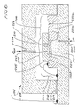
- a differential pressure transmitter 10 measures a difference between two applied pressures P1 and P2 pressurizing an overpressure protection device 12.
- the overpressure protection device 12 couples the two applied pressures to pressure sensors in a multi sensor assembly 14 and protects the multi sensor assembly 14 when differential pressures greater than a preselected limit are applied.
- Use of the shared overpressure protection device 12 avoids the need for integral overpressure protection in each pressure sensor in the sensor assembly 14.
- Clamp 15 clamps the overpressure protection device 12 and the multi sensor assembly 14 together.
- the electrical output from the multi sensor assembly 14 is connected to control electronics 16, which controls the sensor output in a known manner and provide output representative of the differential pressure to a loop 18, typically signalling according to a two-wire current loop (e.g. 4-20mA) communication standard.
- Overpressure protection device 12 is formed of an upper section 19a and a lower section 19b which are joined along an interface 19c using gold o-rings 27,27 or other suitable seals.
- the lower section 19b has two threaded holes 25,25 for mounting.
- the deflection of isolator diaphragm 20 by the applied pressure P1 pressurizes the volume of substantially incompressible isolator fluid 24, transmitting the pressure to multi sensor assembly 14 via passageways 26, 28 and 30 and to an overpressure cavity 34 via passageway 32.
- isolator diaphragm 22 couples applied pressure P2 through a volume of substantially incompressible fluid 36 to an overpressure cavity 44 via passageways 38,40 and 42 and to multi sensor assembly 14 via passageway 46.
- the fluid volumes are preferably chosen so that at low temperatures, the isolator diaphragms do not bottom against the isolator diaphragm supports when the difference between the applied pressures is within a preselected pressure limit. Accordingly, the fluid volume must be selected so that its expansion at high temperature does not apply excessive pressure to the inner major side of the isolator diaphragms, distending them and introducing measurement errors.
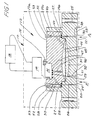
- FIG. 2 A first preferred embodiment of the multi sensor assembly 14 of FIG. 1 is shown in FIG. 2.
- Pressure inlets 80 and 82 in a ceramic header 84 couple incompressible isolator fluids 24 and 36 to the integrated sensor block 86 made of a silicon base 107 and a glass cap 105 sealed together.
- the integrated sensor block 86 comprises a differential pressure sensor 88, an additional pressure sensor 90 and a temperature sensor 92.
- the temperature sensor 92 measures temperature near the differential pressure sensors 88 and 90 and the electronics 16 uses its output to compensate temperature induced pressure sensor errors in a known manner.
- a ceramic cap 94 is joined to the ceramic header 84 by suitable means such as glass frit seal 96.
- a metal feedthrough 100 is deposited under the glass frit seal 96 to connect electrical signals from the integrated sensor block 86 to the exterior of the sealed multi sensor assembly 14.
- Ball bonded wire bundles 98 and 102 or other connective devices conduct electrical signals from the integrated sensor block 86 to the metal feedthrough 100 and from there to the electronics 16.
- the electronics 16 combines the outputs of the pressure sensors 88 and 90 to provide a single improved output representing differential pressure.
- the output can be an average of the two sensed pressures, provided that the two sensed pressures have substantially the same value.
- the transmitter can provide an output signal indicating a transmitter malfunction, e.g.
- the pressure sensors have PMRs different from one or each other and can be arranged in order of successively widening PMRs.
- the sensor having the narrowest PMR is the most accurate pressure sensor and the sensor having the widest PMR is the sensor with the least accuracy.
- the PMR of the transmitter is the same as the PMR of the sensor having the widest PMR.
- URL upper range limit
- the electronics select the output of the more accurate sensor, which has the narrower PMR, for conversion to transmitter output at pressures within the PMR of the most accurate sensor.
- the electronics select the output of the pressure sensor with the widest range for conversion to transmitter output. In this way, the electronics select the most accurate pressure sensor output at a given measured pressure.
- the differential pressure sensors 88 and 90 are capacitive pressure sensors fabricated of a brittle material such as silicon.
- This embodiment uses batch fabrication, where multiple sensors are fabricated simultaneously on a single substrate of brittle material. Usually multiple substrates are processed together in a group, typically resulting in a lower cost of fabrication than if each sensor were fabricated singly.
- An advantage of this manufacturing technique is to ensure that processing variations between groups of substrates are small, promoting tight control over sensor specifications.
- a further advantage is that the two pressure sensors 88 and 90 are adjacent to each other on the silicon base 107, so that the amount of process variation between these batch fabricated sensors is smaller than the process variations for two other pressure sensors far apart on the substrate.
- photolithographic variations which affect dimensions of components are all contributing factors to overall variation in sensor performance.
- Process variations are usually non-uniform across the substrate and depend on the type of processing equipment and sequence.
- the capacitive sensing functions of pressure sensor 88 and 90 are performed by two pairs of metal electrodes 103a,103b, deposited on opposite facing sides of two cavities 104a,104b, respectively forming a capacitor in each of the differential pressure sensors 88 and 90.
- the difference in pressure between isolator fluid 24 and 36 deflects the diaphragms 108a,108b, changing the spacing in each pair of metal electrodes 103a,103b and effecting a change in capacitance.
- the additional differential pressure sensor 90 measures a narrower range of differential pressures than differential pressure sensor 88 and has bidirectional overpressure stops 110a,110b for protection from higher pressures measured by the differential pressure sensor 88.
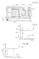
- FIG. 2A is a plan view of the silicon base 107, showing the metal electrodes 103a,103b and the temperature sensor 92.
- FIG. 3A typical maximum non-correctable error of the outputs of the two differential pressure sensors 88 and 90 as a function of the PMR of transmitter 10 is shown.
- the vertical axis 120 shows maximum non-correctable sensor error as a percentage of the URL of transmitter 10 and the horizontal axis 122 shows applied pressure as a percentage of the PMR of transmitter 10.
- the maximum non-correctable error of differential pressure sensor 88 represented at line 124, intercepts the vertical axis at E.
- the PMR of this sensor is substantially the same as the transmitter 10 PMR, represented at the 100% on line 128.
- the maximum non-correctable error for additional differential pressure sensor 90 intercepts the vertical axis at E/4 and its PMR extends to 25% of the URL of transmitter 10, represented at line 129.
- the maximum non-correctable error is substantially independent of pressure and is proportional to the sensor's URL. Because the pressure sensor 88 has a PMR four times larger than that of pressure sensor 90, the maximum non-correctable error is four times larger as well. In other words, a sensor having a wide measurement range has more non-correctable error than a sensor having a narrower measurement range.
- the transmitter 10 maximum non-correctable error combines the error characteristics of the two sensors and is shown in FIG. 3B.
- the maximum non-correctable transmitter 10 error represented at line 130, is reported as a percentage of transmitter URL on the vertical axis 132 and applied pressure as a percentage of PMR of transmitter 10 on the horizontal axis 134.
- Added transmitter capability is demonstrated because of the fourfold decrease in maximum errors during approximately the first 25% of the transmitter 10 PMR, contributed by the additional differential pressure sensor 90.
- the electronics select the output of the most accurate sensor at a given pressure.
- the overpressure limit of the additional differential pressure sensor 90 is exceeded and one of the sensor's overpressure protection stops 110a or 110b is engaged to prevent further deflection of the diaphragm 108b.
- This is different than the overpressure protection for the transmitter, which protects all the sensors in the transmitter by bottoming an isolator diaphragm against an isolator diaphragm support.
- transmitter 10 there is an added capability in transmitter 10 because the maximum non-correctable error during the first 25% of the transmitter 10 PMR is four times less than the maximum non-correctable error during the remainder of the transmitter 10 range. This is important for pressure measurements close to the transmitter's lower range limit, since error as a percentage of measurement becomes larger as the pressure approaches the lower range limit. From FIG. 3B, the extended measurement capability is expressed alternatively by noting that the presence of differential pressure sensor 88 extends the transmitter PMR, although at the expense of higher levels of error.
- An alternative method of extending the measurement capability of the transmitter 10 is to incorporate at least two pressure sensors having substantially the same PMR in the transmitter 10.
- the transmitter 10 span is unaffected and the level of accuracy throughout the PMR is constant.
- this redundancy extends the measurement capability of the transmitter 10 by providing extra security for critical measurements and transmitter self-correction features.
- a preselected pressure limit of transmitter 10 is shown as 150% of the transmitter's PMR at 140, and is chosen such that all structural damage occurs at applied differential pressures higher than the limit.
- maximum non-correctable error increases steadily at pressures exceeding the transmitter overpressure limit, represented by line segment 142.
- the transmitter 10 operates according to a known set of specifications before and after applications of pressures exceeding the preselected limit.
- SAMA Scientific Apparatus Makers Association
- PMC Measurement and Control
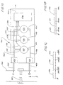
- FIG. 4A shows a transmitter represented by functional block 400 measuring applied pressure P1 and P2 through taps 403,403, located upstream and downstream from a flow restriction 401 in a pipe 402.
- the flow in pipe 402, represented by an arrow f, is substantially proportional to the square root of the difference between P1 and P2.
- the pressure sensor having the narrowest PMR, or equivalently the additional pressure sensor 422 has the least maximum non-correctable error.
- the electronics 428 selects the most accurate of the pressure sensor outputs 426, 420 and 414, converting them to output 430 representing either flow in the pipe 402 or the applied differential pressure across the orifice 401.
- Pressure transmitter 400 measures flow in process control.
- the percentage of flow measurement range affected by increased accuracy of additional pressure sensors is larger than the percentage of pressure measurement range affected by the same additional pressure sensors in a pressure measurement application. The difference is attributable to the non-linear relationship between flow and pressure.
- FIGS. 4B and 4C show the percentage of measurement range affected by the additional pressure sensors 416,422 in pressure and flow measurements, respectively.
- FIG. 4B shows differential pressure as a percentage of transmitter 400 PMR, extending from zero to the URL applied pressure.
- Additional pressure sensor 422 output represented at line 426 is selected for conversion to transmitter 400 output in the range indicated at 430 between zero applied pressure and .125URL.
- Additional pressure sensor 416 output, represented at line 420 is selected for conversion to transmitter 400 output in the range indicated at 432 between .125URL and .50URL.
- first pressure sensor 410 output represented by line 414, is selected for conversion to transmitter 400 output for range indicated at 434 of the transmitter measurement range.
- the additional pressure sensors provide increased accuracy throughout 50% of the flow measurement range.
- FIG. 4C shows flow as a percentage of transmitter 400 flow measurement range.
- f k (P) 1 ⁇ 2 where f is flow, k is a proportionality constant and P is the difference between P1 and P2.
- the range of additional pressure sensor 422, indicated at 430 is expanded to the range indicated at 436 between zero and .35k(URL) 1 ⁇ 2 .
- the range of additional pressure sensor 416, indicated at 432 is expanded to the range indicated at 438 between .35k(URL) 1 ⁇ 2 and .71k(URL) 1 ⁇ 2 .
- the range of remaining first pressure sensor 410 becomes the flow measurement range indicated at 440 between .71k(URL) 1 ⁇ 2 and k(URL) 1 ⁇ 2 . Increased accuracy is achieved throughout 71% of the flow measurement range, as contrasted to 50% of the pressure measurement range of FIG. 4B.
- the improved transmitter displays a higher percentage of accuracy as a percentage of measurement range in a flow measurement application than in a pressure measurement application.
- a gauge pressure transmitter 130 measuring a difference between an applied pressure P1 and a gauge reference pressure, P REF .
- the pressure P1 acts on the overpressure protection device 132 which couples the applied pressure to pressure sensors in a multi sensor assembly 134.
- a clamp 136 or other appropriate hardware fixes the multi sensor assembly 134 to the overpressure protection device 132.
- Outputs indicated at 133 electrically connect the multi sensor assembly 134 to electronics 138.
- the electronics 138 operates on the output in a known manner and provide output representative of the applied gauge pressure to a loop 140, typically signalling according to a two-wire 4-20mA communication standard.
- the overpressure protection device 132 is formed in lower section 168 and upper section 170 of stainless steel or some other material providing structural integrity and joined along an interface 172.
- the upper section 170 is sealed to the lower section 168 using gold o-ring 182,183,183 or other suitable seal.
- a volume of substantially incompressible isolator fluid 144 enters the overpressure protection device 132 at casting opening 174 sealed by a ball and screw combination 178 or other suitable seal.
- the lower section 168 has two threaded holes 180,180 for mounting. Applied pressure P1 deflects the isolator diaphragm 142 of the overpressure protection device 132.
- the pressure difference between the volume of isolator fluid 144 and the reference gauge pressure, P REF deflect an overpressure diaphragm 164 separating the two overpressure cavities 154 and 160.
- P REF the overpressure protection device 132 inhibits transfer of the applied pressure to the multi pressure assembly 134 by displacing enough isolator fluid 144 into the overpressure cavity 154 to substantially fully support the isolator diaphragm 142 against isolator diaphragm support 166.
- the overpressure cavity 154 must accommodate the volume of isolator fluid 144 normally lying behind the isolator diaphragm 142 when an overpressure condition occurs.
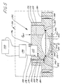
- FIG. 6 a first preferred embodiment of the multi sensor assembly 134 is shown.
- a pressure inlet 200 in a ceramic header 202 provides passage for the pressurized isolator fluid 144 from passageway 150 into an integrated sensor block 204 comprising a gauge pressure sensor 206 and an additional gauge pressure sensor 208.
- a ceramic cap 210 is joined to the ceramic header 202 by suitable means such as glass frit seal 212.
- a metal feedthrough 214 is deposited under the glass frit seal 212 to connect electrical signals from the integrated sensor block 204 to the exterior of the sealed multi sensor assembly 134.
- Ball bonded wire bundles 216 and 218 or other similar conductive devices connect the electrical signals from the integrated sensor block 204 to the metal feedthrough 214 and from there to the electronics 138.
- Integrated sensor block 204 comprises gauge pressure sensors 206 and 208, which sense pressure by means of piezoresistive strain gauges 222a,222b, formed by diffusion, implantation or other known manner of dopant introduction on sensing diaphragms 221a,221b for gauge pressure sensors 206,208, respectively.
- Other pressure sensing mechanisms such as changes in capacitance, resonant frequency or polarization of light may be used and various versions of all four mechanisms are known.
- a passageway 226 in the ceramic cap 202 introduces the gauge reference pressure, P REF , to the gauge pressure sensors 206 and 208, the difference between the gauge reference pressure and the isolator fluid 144 pressure deflecting and stressing the sensing diaphragms 221a,221b.
- Gauge pressure sensor 206 measures a wider span of pressures than additional gauge pressure sensor 208, necessitating a unidirectional pressure stop 224 to protect the latter pressure sensor against pressures measured by the former even though the maximum deflection of most piezoresistive strain gauges is on the order of one to five microns. Permanent degradation in sensor performance will typically occur after application of pressures exceeding five times the highest specified pressure the sensor measures.
- the unidirectional overpressure stop 224 is a silicon boss which bottoms against an inner surface of a depression 227 formed in an upper glass support 225. As in the preferred embodiment of the differential transmitter shown in FIG. 1, this additional gauge pressure sensor 208 extends the measurement capability of the gauge transmitter 130 by increasing transmitter accuracy throughout the lower regions of the transmitter span.
- FIG. 7 an alternate multi sensor assembly 134 for the gauge transmitter 130 explained in FIG. 5 is shown.
- a pressure inlet 300 in a ceramic header 302 provides for passage of the isolator fluid 144 into an integrated sensor block 304 comprising a gauge pressure sensor 306 and an additional gauge pressure sensor 308.
- a ceramic cap 310 is joined to the ceramic header 302 by suitable means such as glass frit seal 312.
- a passageway 313 allows the gauge reference pressure, P REF , to access the two gauge pressure sensors 306 and 308.
- a metal feedthrough 314 is deposited under the glass frit seal 312 to connect electrical signals from the integrated sensor block 304 to the exterior of the sealed multi sensor assembly 134.
- Ball bonded wire bundles 316 and 318 or similar conductive devices connect the electrical signals from the integrated sensor block to the metal feedthrough 314 and from there to the electronics 138.
- the integrated sensor block 304 comprises an upper section 351 and a lower section 357.
- Two passageways 353,352 couple the gauge reference pressure, P REF , to the gauge pressure sensor 306 and the additional gauge pressure sensor 308, respectively.
- the gauge pressure sensor 306 is an optical pressure sensor and has a light source 354, an elastomeric crystal 355 which polarizes light as a function of the pressure applied to the crystal and a light receiver 356, all affixed to the lower section 357 by glass frit seals 358,358,358.
- the additional gauge pressure sensor 308 has a piezoelectric crystal 359 bridging a depression 360 in the lower section 357 of the integrated sensor block 304.
- a corresponding recess 361 in the upper section 351 fits over the piezoelectric crystal 359 and glass frit seals 362,362 secure the crystal to the upper section.
- Another glass frit seal 363 seals both the piezoelectric crystal 359 to the lower section 357 and the upper section 351 to the lower section 357.
- Two electrical signals of opposite phase having appropriate frequency are connected to two metallized areas 364a,364b on one side of the crystal. The crystal resonates as a function of applied frequency and pressure, and metallized area 365 on the other side of the crystal conducts this signal via ball bonded wires to the exterior of the sealed multi sensor assembly 134.
Landscapes
- Physics & Mathematics (AREA)
- General Physics & Mathematics (AREA)
- Chemical & Material Sciences (AREA)
- Analytical Chemistry (AREA)
- Fluid Mechanics (AREA)
- Engineering & Computer Science (AREA)
- Ceramic Engineering (AREA)
- Measuring Fluid Pressure (AREA)
- Transmitters (AREA)
Abstract
Claims (12)
- Transmetteur (10) pour mesurer au moins une pression appliquée et délivrer un signal de sortie représentatif de la pression appliquée, comprenant un premier capteur de pression (88,206,306,410) qui comporte au moins une entrée (80,82,200,300,403); des moyens de protection contre les surpressions (12,132,404) pour transmettre la pression appliquée à l'entrée (82,200,300,410) du capteur de pression, comportant des moyens destinés à contenir un volume de fluide isolant pratiquement incompressible aboutissant à l'entrée de pression, la pression appliquée amenant un élément mobile (20,22) à agir sur le fluide isolant lorsque la pression appliquée varie; les moyens de protection contre les surpressions (12) limitant l'élévation additionnelle de la pression du fluide qui agit à l'entrée (80,82) du capteur lorsque la pression appliquée dépasse une limite présélectionnée; le transmetteur étant caractérisé par au moins un capteur de pression supplémentaire (90,208,308,416,422) qui comporte une entrée de pression (80,82,200,300,418,424) exposée au volume de fluide isolant, de sorte que le premier capteur de pression et le capteur de pression supplémentaire (88,90,206,208,416,422) se partagent les moyens de protection contre les suppressions (12).
- Transmetteur (10) selon la revendication 1, caractérisé en outre en ce qu'il mesure deux pressions appliquées et délivre un signal de sortie représentatif des deux pressions appliquées, le premier capteur de pression comprenant un premier capteur de pression différentielle (88,410) qui comporte une paire d'entrées de pression (80,82,412) et les moyens de protection contre les surpressions (12,404) qui relient de manière isolante les deux pressions appliquées à une paire correspondante de volumes séparés (34,44,406,406) de fluide isolant pratiquement incompressible, sur chacun desquels agit un élément mobile séparé et qui sont reliés respectivement à la paire d'entrées de pression (80,82,412,418,424), les moyens de protection contre les surpressions (12,404) limitant l'élévation de la pression de fluide isolant de l'un des volumes de fluide isolant lorsque la pression différentielle appliquée dépasse une limite présélectionnée, le capteur de pression supplémentaire (90,416,422) comprenant un capteur de pression différentielle supplémentaire (90,416,422) qui comporte une paire d'entrées de pression (80,82,418,424), chaque entrée étant exposée à l'un des volumes partiels (34,44) de fluide isolant, de sorte que les capteurs de pression différentielle supplémentaires (90,416,422) se partagent les moyens de protection contre les surpressions (12,404), de tels capteurs de pression différentielle supplémentaires (90,416,422) élargissant les possibilités de mesure du transmetteur.
- Transmetteur selon la revendication 1 ou 2, dans lequel au moins deux des capteurs de pression (88,90) ont des plages de mesure de pression qui sont nettement différentes l'une de l'autre.
- Transmetteur selon la revendication 1 ou 2, dans lequel au moins deux des capteurs de pression (88,90) ont des plages de mesure de pression qui sont sensiblement les mêmes, et des moyens électroniques sont prévus pour combiner les signaux de sortie du premier capteur de pression et du capteur de pression supplémentaire et délivrer un signal de sortie de transmetteur.
- Transmetteur selon l'une quelconque des revendications 1 à 3, dans lequel la limite de pression présélectionnée est choisie dans le groupe de pressions supérieures à une pression maximale mesurée par les capteurs de pression, mais inférieures au quintuple de cette pression.
- Transmetteur selon l'une quelconque des revendications 1 à 5, dans lequel l'un au moins des capteurs de pression (88,90) est fait, en partie ou entièrement, d'un matériau cassant (86).
- Transmetteur selon l'une quelconque des revendications 1 à 5, dans lequel deux des capteurs de pression (88,90,206,306) sont faits, en partie ou entièrement, d'une seule pièce de matériau cassant.
- Transmetteur selon l'une quelconque des revendications 1 à 7, caractérisé en outre par un capteur de température (92) qui mesure une température dans le transmetteur pour compenser une erreur due à la température dans l'un ou plusieurs des capteurs de pression (88,90).
- Transmetteur (10) selon l'une quelconque des revendications 1 à 8, dans lequel les moyens de protection contre les surpressions (12) comprennent une chambre (34,44) qui change de volume lorsque la pression appliquée varie, afin de permettre que l'élément mobile (20,22) entre en contact avec une butée.
- Transmetteur selon la revendication 9, caractérisé en outre en ce que la chambre est divisée par une membrane de surpression (45) en une paire de cavités (34, 44) remplies chacune de l'un des volumes séparés de fluide isolant, la différence de pression entre les deux cavités (34,44) déformant la membrane de surpression (45).
- Transmetteur (10) selon l'une quelconque des revendications 1 à 10, dans lequel le capteur de pression supplémentaire (90,208) détecte les pressions dans une plage plus étroite que le premier capteur de pression (88,204) et comporte des moyens (110a,110b,224) pour éviter l'endommagement du capteur de pression supplémentaire (90,208) lorsque la pression à l'entrée dépasse la plage du capteur de pression supplémentaire (90) mais est dans les limites de la plage du premier capteur de pression.
- Transmetteur selon l'une quelconque des revendications 1 à 11, avec des moyens électroniques (16,138,42B) pour combiner les signaux de sortie du premier capteur et du capteur supplémentaire et délivrer un signal de sortie de transmetteur.
Applications Claiming Priority (3)
| Application Number | Priority Date | Filing Date | Title |
|---|---|---|---|
| US365922 | 1982-04-08 | ||
| US07/365,922 US4949581A (en) | 1989-06-15 | 1989-06-15 | Extended measurement capability transmitter having shared overpressure protection means |
| PCT/US1990/003430 WO1990015975A1 (fr) | 1989-06-15 | 1990-06-14 | Transmetteur capable de proceder a des mesures etendues, dote de moyens de protection de surpression partages |
Publications (3)
| Publication Number | Publication Date |
|---|---|
| EP0572375A4 EP0572375A4 (fr) | 1992-02-11 |
| EP0572375A1 EP0572375A1 (fr) | 1993-12-08 |
| EP0572375B1 true EP0572375B1 (fr) | 1995-11-29 |
Family
ID=23440950
Family Applications (1)
| Application Number | Title | Priority Date | Filing Date |
|---|---|---|---|
| EP90910023A Expired - Lifetime EP0572375B1 (fr) | 1989-06-15 | 1990-06-14 | Transmetteur capable de proceder a des mesures etendues, dote de moyens de protection de surpression partages |
Country Status (7)
| Country | Link |
|---|---|
| US (1) | US4949581A (fr) |
| EP (1) | EP0572375B1 (fr) |
| JP (1) | JP2898751B2 (fr) |
| AU (1) | AU637379B2 (fr) |
| CA (1) | CA2056391A1 (fr) |
| DE (1) | DE69023930T2 (fr) |
| WO (1) | WO1990015975A1 (fr) |
Families Citing this family (54)
| Publication number | Priority date | Publication date | Assignee | Title |
|---|---|---|---|---|
| GB8718637D0 (en) * | 1987-08-06 | 1987-09-09 | Spectrol Reliance Ltd | Sealing electrical feedthrough |
| US5022270A (en) * | 1989-06-15 | 1991-06-11 | Rosemount Inc. | Extended measurement capability transmitter having shared overpressure protection means |
| US5323656A (en) * | 1992-05-12 | 1994-06-28 | The Foxboro Company | Overpressure-protected, polysilicon, capacitive differential pressure sensor and method of making the same |
| US5333504A (en) * | 1992-09-01 | 1994-08-02 | Rosemount Inc. | High overpressure low range pressure sensor |
| US5349491A (en) * | 1992-11-06 | 1994-09-20 | Kavlico Corporation | Pre-stressed pressure transducer and method of forming same |
| FI1096U1 (fi) * | 1993-04-13 | 1993-12-28 | Gunnar Sundholm | Maet- och transmitterapparat |
| AU7562394A (en) * | 1993-09-07 | 1995-03-27 | Rosemount Inc. | Multivariable transmitter |
| US5606513A (en) * | 1993-09-20 | 1997-02-25 | Rosemount Inc. | Transmitter having input for receiving a process variable from a remote sensor |
| GB9321398D0 (en) * | 1993-10-16 | 1993-12-08 | Lucas Ind Plc | Differential pressure transducer |
| JP3114570B2 (ja) * | 1995-05-26 | 2000-12-04 | オムロン株式会社 | 静電容量型圧力センサ |
| US5757608A (en) * | 1996-01-25 | 1998-05-26 | Alliedsignal Inc. | Compensated pressure transducer |
| US5706565A (en) * | 1996-09-03 | 1998-01-13 | Delco Electronics Corporation | Method for making an all-silicon capacitive pressure sensor |
| US5936164A (en) * | 1997-08-27 | 1999-08-10 | Delco Electronics Corporation | All-silicon capacitive pressure sensor |
| US6047244A (en) * | 1997-12-05 | 2000-04-04 | Rosemount Inc. | Multiple range transition method and apparatus for process control sensors |
| US6473711B1 (en) | 1999-08-13 | 2002-10-29 | Rosemount Inc. | Interchangeable differential, absolute and gage type of pressure transmitter |
| US6643610B1 (en) | 1999-09-24 | 2003-11-04 | Rosemount Inc. | Process transmitter with orthogonal-polynomial fitting |
| US6484107B1 (en) | 1999-09-28 | 2002-11-19 | Rosemount Inc. | Selectable on-off logic modes for a sensor module |
| US7134354B2 (en) | 1999-09-28 | 2006-11-14 | Rosemount Inc. | Display for process transmitter |
| US7109883B2 (en) | 2002-09-06 | 2006-09-19 | Rosemount Inc. | Low power physical layer for a bus in an industrial transmitter |
| US7415883B2 (en) * | 2004-06-28 | 2008-08-26 | Zuli Holdings Ltd | Method for protecting resonating sensors and open protected resonating sensors |
| US8162839B2 (en) * | 2003-08-27 | 2012-04-24 | Microtech Medical Technologies Ltd. | Protected passive resonating sensors |
| DE10347861A1 (de) * | 2003-10-10 | 2005-04-28 | Endress & Hauser Gmbh & Co Kg | Meßaufnehmer |
| US7036381B2 (en) | 2004-06-25 | 2006-05-02 | Rosemount Inc. | High temperature pressure transmitter assembly |
| US7190053B2 (en) | 2004-09-16 | 2007-03-13 | Rosemount Inc. | Field device incorporating circuit card assembly as environmental and EMI/RFI shield |
| US7287432B2 (en) * | 2005-11-17 | 2007-10-30 | Rosemount Inc. | Process transmitter with overpressure vent |
| DE102006004086A1 (de) * | 2006-01-25 | 2007-08-09 | Quantum Hydrometrie Gesellschaft für Meß- und Systemtechnik mbH | Füllstandsmeßvorrichtung zum Messen eines Füll- oder Pegelstandes |
| US7525419B2 (en) | 2006-01-30 | 2009-04-28 | Rosemount Inc. | Transmitter with removable local operator interface |
| EP2275793A1 (fr) | 2006-05-23 | 2011-01-19 | Sensirion Holding AG | Capteur de pression comportant une chambre et procédé de fabrication de celui-ci |
| US7467555B2 (en) * | 2006-07-10 | 2008-12-23 | Rosemount Inc. | Pressure transmitter with multiple reference pressure sensors |
| US7461562B2 (en) | 2006-08-29 | 2008-12-09 | Rosemount Inc. | Process device with density measurement |
| DE102006057809A1 (de) | 2006-12-06 | 2008-06-12 | Ruprecht-Karls-Universität Heidelberg | Intubationsschlauch |
| JP5663475B2 (ja) | 2008-05-23 | 2015-02-04 | ローズマウント インコーポレイテッド | エネルギの流れの計算を備える多変数プロセス流体の流れの装置 |
| EP2159558A1 (fr) * | 2008-08-28 | 2010-03-03 | Sensirion AG | Procédé de fabrication d'un capteur de pression intégré |
| EP2342604B1 (fr) * | 2008-10-01 | 2019-11-13 | Rosemount Inc. | Système de contrôle de processus comprenant des calculs de tests en ligne et hors ligne pour des transmetteurs de processus industriels |
| US7997142B2 (en) * | 2009-07-31 | 2011-08-16 | Continental Automotive Systems, Inc. | Low pressure sensor device with high accuracy and high sensitivity |
| US8340791B2 (en) | 2009-10-01 | 2012-12-25 | Rosemount Inc. | Process device with sampling skew |
| DE102009055149A1 (de) * | 2009-12-22 | 2011-06-30 | Endress + Hauser GmbH + Co. KG, 79689 | Überlastsicherer, Drucksensor, insbesondere Differenzdrucksensor |
| IT1397666B1 (it) * | 2009-12-22 | 2013-01-18 | Guidotti | Trasduttore differenziale estensimetrico con dispositivo di protezione integrato. |
| DE202009017430U1 (de) * | 2009-12-23 | 2011-05-05 | Liebherr-Werk Ehingen Gmbh | Sensor |
| US8334788B2 (en) | 2010-03-04 | 2012-12-18 | Rosemount Inc. | Process variable transmitter with display |
| US8276458B2 (en) | 2010-07-12 | 2012-10-02 | Rosemount Inc. | Transmitter output with scalable rangeability |
| FR2982023B1 (fr) * | 2011-10-26 | 2015-03-06 | Auxitrol Sa | Structure micromecanique a membrane deformable et a protection contre de fortes deformations |
| US9121743B2 (en) | 2012-05-31 | 2015-09-01 | Rosemount Inc. | Process variable transmitter system with analog communication |
| US8752433B2 (en) * | 2012-06-19 | 2014-06-17 | Rosemount Inc. | Differential pressure transmitter with pressure sensor |
| US8701496B1 (en) * | 2013-02-27 | 2014-04-22 | Honeywell International Inc. | Systems and methods for a pressure sensor having a two layer die structure |
| US10151647B2 (en) | 2013-06-19 | 2018-12-11 | Honeywell International Inc. | Integrated SOI pressure sensor having silicon stress isolation member |
| EP2871455B1 (fr) | 2013-11-06 | 2020-03-04 | Invensense, Inc. | Capteur de pression |
| EP2871456B1 (fr) | 2013-11-06 | 2018-10-10 | Invensense, Inc. | Capteur de pression et procédé de fabrication d'un capteur de pression |
| EP3076146B1 (fr) | 2015-04-02 | 2020-05-06 | Invensense, Inc. | Capteur de pression |
| JP6759454B2 (ja) * | 2016-09-27 | 2020-09-23 | ローズマウント インコーポレイテッド | 高圧超高圧シリコンダイ圧力センサ |
| DE102016118526A1 (de) | 2016-09-29 | 2018-03-29 | Krohne Messtechnik Gmbh | Leitfähigkeitsmessgerät zur Messung einer elektrischen Leitfähigkeit eines flüssigen Mediums |
| US11225409B2 (en) | 2018-09-17 | 2022-01-18 | Invensense, Inc. | Sensor with integrated heater |
| CN113785178B (zh) | 2019-05-17 | 2024-12-17 | 应美盛股份有限公司 | 气密性改进的压力传感器 |
| DE102023114003A1 (de) * | 2023-05-26 | 2024-11-28 | Bürkert Werke GmbH & Co. KG | Durchflussmessgerät sowie Massendurchflussregler und Massendurchflussmesser mit einem solchen Durchflussmessgerät |
Family Cites Families (20)
| Publication number | Priority date | Publication date | Assignee | Title |
|---|---|---|---|---|
| AU4863272A (en) * | 1971-11-25 | 1974-05-09 | Halcyon Proteins Pty. Limited | A PRESSURE GAUGE ISOLATOR Specification |
| US4086815A (en) * | 1975-07-24 | 1978-05-02 | Fuji Electric Co., Ltd. | Device for use in sensing pressures |
| JPS5233575A (en) * | 1975-09-09 | 1977-03-14 | Fuji Electric Co Ltd | Differential pressure measuring device |
| DE2712846A1 (de) * | 1976-03-24 | 1977-11-24 | Ict Instr Inc | Messumformer zum messen von druckunterschieden |
| JPS5687196A (en) * | 1979-12-19 | 1981-07-15 | Hitachi Ltd | Differential pressure transmitter |
| US4370890A (en) * | 1980-10-06 | 1983-02-01 | Rosemount Inc. | Capacitive pressure transducer with isolated sensing diaphragm |
| JPS58176532A (ja) * | 1982-04-09 | 1983-10-17 | Fuji Electric Co Ltd | 圧力測定装置 |
| US4445383A (en) * | 1982-06-18 | 1984-05-01 | General Signal Corporation | Multiple range capacitive pressure transducer |
| US4598381A (en) * | 1983-03-24 | 1986-07-01 | Rosemount Inc. | Pressure compensated differential pressure sensor and method |
| US4713969A (en) * | 1983-09-30 | 1987-12-22 | Kabushiki Kaisha Toshiba | Differential pressure transmission apparatus |
| US4528855A (en) * | 1984-07-02 | 1985-07-16 | Itt Corporation | Integral differential and static pressure transducer |
| JPS6183930A (ja) * | 1984-09-29 | 1986-04-28 | Toshiba Corp | 圧力・差圧伝送器 |
| US4574640A (en) * | 1984-11-29 | 1986-03-11 | Bourns Instruments, Inc. | Integrated dual-range pressure transducer |
| US4693121A (en) * | 1985-06-05 | 1987-09-15 | The Foxboro Company | Differential-pressure measuring apparatus with improved overpressure protection |
| JPS638524A (ja) * | 1986-06-30 | 1988-01-14 | Yamatake Honeywell Co Ltd | 差圧発信器 |
| US4773269A (en) * | 1986-07-28 | 1988-09-27 | Rosemount Inc. | Media isolated differential pressure sensors |
| US4732043A (en) * | 1986-08-11 | 1988-03-22 | Bell Microsensors, Inc. | System and method for obtaining digital outputs from multiple transducers |
| US4790192A (en) * | 1987-09-24 | 1988-12-13 | Rosemount Inc. | Silicon side by side coplanar pressure sensors |
| US4818994A (en) * | 1987-10-22 | 1989-04-04 | Rosemount Inc. | Transmitter with internal serial bus |
| JPH01141328A (ja) * | 1987-11-27 | 1989-06-02 | Hitachi Ltd | 差圧伝送器 |
-
1989
- 1989-06-15 US US07/365,922 patent/US4949581A/en not_active Expired - Lifetime
-
1990
- 1990-06-14 WO PCT/US1990/003430 patent/WO1990015975A1/fr not_active Ceased
- 1990-06-14 JP JP2509239A patent/JP2898751B2/ja not_active Expired - Fee Related
- 1990-06-14 CA CA002056391A patent/CA2056391A1/fr not_active Abandoned
- 1990-06-14 AU AU58508/90A patent/AU637379B2/en not_active Ceased
- 1990-06-14 DE DE69023930T patent/DE69023930T2/de not_active Expired - Fee Related
- 1990-06-14 EP EP90910023A patent/EP0572375B1/fr not_active Expired - Lifetime
Also Published As
| Publication number | Publication date |
|---|---|
| AU637379B2 (en) | 1993-05-27 |
| US4949581A (en) | 1990-08-21 |
| DE69023930D1 (de) | 1996-01-11 |
| EP0572375A4 (fr) | 1992-02-11 |
| WO1990015975A1 (fr) | 1990-12-27 |
| AU5850890A (en) | 1991-01-08 |
| DE69023930T2 (de) | 1996-06-05 |
| JPH04506257A (ja) | 1992-10-29 |
| EP0572375A1 (fr) | 1993-12-08 |
| JP2898751B2 (ja) | 1999-06-02 |
| CA2056391A1 (fr) | 1990-12-16 |
Similar Documents
| Publication | Publication Date | Title |
|---|---|---|
| EP0572375B1 (fr) | Transmetteur capable de proceder a des mesures etendues, dote de moyens de protection de surpression partages | |
| US5022270A (en) | Extended measurement capability transmitter having shared overpressure protection means | |
| US4986127A (en) | Multi-functional sensor | |
| US5677493A (en) | Composite condition detection apparatus for detecting static pressure, differential pressure and temperature of a process | |
| CA2455694C (fr) | Capteur de pression | |
| US5714690A (en) | Piezoresistive silicon pressure sensor manufacture implementing long diaphragms with large aspect ratios | |
| US5637802A (en) | Capacitive pressure sensor for a pressure transmitted where electric field emanates substantially from back sides of plates | |
| EP0451193B1 (fr) | Capteur de pression multimodule | |
| US7775117B2 (en) | Combined wet-wet differential and gage transducer employing a common housing | |
| EP0164413B1 (fr) | Transducteur de pression | |
| US20030205089A1 (en) | Absolute pressure sensor | |
| CA1239806A (fr) | Sonde capacitive faite de matiere frangible | |
| EP0083496B1 (fr) | Transducteur de pression à semi-conducteur | |
| US4741214A (en) | Capacitive transducer with static compensation | |
| CA1107982A (fr) | Dispositif reagissant a la pression | |
| EP0080186A2 (fr) | Transducteur de pression à semi-conducteurs | |
| RU2101688C1 (ru) | Двухмембранный тензопреобразователь давления | |
| JP2024117080A (ja) | ダイヤフラムを有するセンサダイ | |
| GB2107924A (en) | Strain gauge pressure transducers | |
| JPH05248974A (ja) | 半導体圧力センサ | |
| JPH0579937A (ja) | 半導体圧力センサ |
Legal Events
| Date | Code | Title | Description |
|---|---|---|---|
| PUAI | Public reference made under article 153(3) epc to a published international application that has entered the european phase |
Free format text: ORIGINAL CODE: 0009012 |
|
| 17P | Request for examination filed |
Effective date: 19911029 |
|
| AK | Designated contracting states |
Kind code of ref document: A1 Designated state(s): DE FR GB IT NL SE |
|
| 17Q | First examination report despatched |
Effective date: 19940420 |
|
| GRAA | (expected) grant |
Free format text: ORIGINAL CODE: 0009210 |
|
| AK | Designated contracting states |
Kind code of ref document: B1 Designated state(s): DE FR GB IT NL SE |
|
| REF | Corresponds to: |
Ref document number: 69023930 Country of ref document: DE Date of ref document: 19960111 |
|
| ITF | It: translation for a ep patent filed | ||
| ET | Fr: translation filed | ||
| PLBE | No opposition filed within time limit |
Free format text: ORIGINAL CODE: 0009261 |
|
| STAA | Information on the status of an ep patent application or granted ep patent |
Free format text: STATUS: NO OPPOSITION FILED WITHIN TIME LIMIT |
|
| 26N | No opposition filed | ||
| PGFP | Annual fee paid to national office [announced via postgrant information from national office to epo] |
Ref country code: FR Payment date: 19990630 Year of fee payment: 10 |
|
| PGFP | Annual fee paid to national office [announced via postgrant information from national office to epo] |
Ref country code: SE Payment date: 19990701 Year of fee payment: 10 |
|
| PGFP | Annual fee paid to national office [announced via postgrant information from national office to epo] |
Ref country code: GB Payment date: 19990702 Year of fee payment: 10 |
|
| PGFP | Annual fee paid to national office [announced via postgrant information from national office to epo] |
Ref country code: NL Payment date: 19990712 Year of fee payment: 10 |
|
| PG25 | Lapsed in a contracting state [announced via postgrant information from national office to epo] |
Ref country code: GB Free format text: LAPSE BECAUSE OF NON-PAYMENT OF DUE FEES Effective date: 20000614 |
|
| PG25 | Lapsed in a contracting state [announced via postgrant information from national office to epo] |
Ref country code: SE Free format text: LAPSE BECAUSE OF NON-PAYMENT OF DUE FEES Effective date: 20000615 |
|
| PG25 | Lapsed in a contracting state [announced via postgrant information from national office to epo] |
Ref country code: NL Free format text: LAPSE BECAUSE OF NON-PAYMENT OF DUE FEES Effective date: 20010101 |
|
| GBPC | Gb: european patent ceased through non-payment of renewal fee |
Effective date: 20000614 |
|
| EUG | Se: european patent has lapsed |
Ref document number: 90910023.2 |
|
| PG25 | Lapsed in a contracting state [announced via postgrant information from national office to epo] |
Ref country code: FR Free format text: LAPSE BECAUSE OF NON-PAYMENT OF DUE FEES Effective date: 20010228 |
|
| NLV4 | Nl: lapsed or anulled due to non-payment of the annual fee |
Effective date: 20010101 |
|
| REG | Reference to a national code |
Ref country code: FR Ref legal event code: ST |
|
| PG25 | Lapsed in a contracting state [announced via postgrant information from national office to epo] |
Ref country code: IT Free format text: LAPSE BECAUSE OF NON-PAYMENT OF DUE FEES;WARNING: LAPSES OF ITALIAN PATENTS WITH EFFECTIVE DATE BEFORE 2007 MAY HAVE OCCURRED AT ANY TIME BEFORE 2007. THE CORRECT EFFECTIVE DATE MAY BE DIFFERENT FROM THE ONE RECORDED. Effective date: 20050614 |
|
| PGFP | Annual fee paid to national office [announced via postgrant information from national office to epo] |
Ref country code: DE Payment date: 20080731 Year of fee payment: 19 |
|
| PG25 | Lapsed in a contracting state [announced via postgrant information from national office to epo] |
Ref country code: DE Free format text: LAPSE BECAUSE OF NON-PAYMENT OF DUE FEES Effective date: 20100101 |