EP0572355A1 - Module for executing the pervaporation of fluids - Google Patents
Module for executing the pervaporation of fluids Download PDFInfo
- Publication number
- EP0572355A1 EP0572355A1 EP93810375A EP93810375A EP0572355A1 EP 0572355 A1 EP0572355 A1 EP 0572355A1 EP 93810375 A EP93810375 A EP 93810375A EP 93810375 A EP93810375 A EP 93810375A EP 0572355 A1 EP0572355 A1 EP 0572355A1
- Authority
- EP
- European Patent Office
- Prior art keywords
- chambers
- pervaporation
- module according
- chamber
- longitudinal end
- Prior art date
- Legal status (The legal status is an assumption and is not a legal conclusion. Google has not performed a legal analysis and makes no representation as to the accuracy of the status listed.)
- Granted
Links
- 238000005373 pervaporation Methods 0.000 title claims abstract description 39
- 239000012530 fluid Substances 0.000 title claims description 11
- 238000010438 heat treatment Methods 0.000 claims abstract description 34
- 239000012465 retentate Substances 0.000 claims abstract description 12
- 239000012528 membrane Substances 0.000 claims description 8
- 239000012466 permeate Substances 0.000 claims description 8
- 239000002184 metal Substances 0.000 claims description 5
- 229910052751 metal Inorganic materials 0.000 claims description 5
- 238000004080 punching Methods 0.000 claims description 3
- 239000000463 material Substances 0.000 claims 1
- 230000003014 reinforcing effect Effects 0.000 claims 1
- 238000009826 distribution Methods 0.000 abstract description 6
- 239000007788 liquid Substances 0.000 description 7
- 238000010276 construction Methods 0.000 description 3
- 238000013461 design Methods 0.000 description 3
- 238000012423 maintenance Methods 0.000 description 3
- 238000009792 diffusion process Methods 0.000 description 2
- 238000001704 evaporation Methods 0.000 description 2
- 230000008020 evaporation Effects 0.000 description 2
- 229910052770 Uranium Inorganic materials 0.000 description 1
- 239000000919 ceramic Substances 0.000 description 1
- 238000001311 chemical methods and process Methods 0.000 description 1
- 210000001520 comb Anatomy 0.000 description 1
- 238000009833 condensation Methods 0.000 description 1
- 230000005494 condensation Effects 0.000 description 1
- 238000003780 insertion Methods 0.000 description 1
- 230000037431 insertion Effects 0.000 description 1
- 238000004519 manufacturing process Methods 0.000 description 1
- 239000007769 metal material Substances 0.000 description 1
- 239000000203 mixture Substances 0.000 description 1
- 238000012856 packing Methods 0.000 description 1
- 238000000926 separation method Methods 0.000 description 1
- 238000003860 storage Methods 0.000 description 1
- JFALSRSLKYAFGM-UHFFFAOYSA-N uranium(0) Chemical compound [U] JFALSRSLKYAFGM-UHFFFAOYSA-N 0.000 description 1
- 238000009834 vaporization Methods 0.000 description 1
- 230000008016 vaporization Effects 0.000 description 1
Images
Classifications
-
- B—PERFORMING OPERATIONS; TRANSPORTING
- B01—PHYSICAL OR CHEMICAL PROCESSES OR APPARATUS IN GENERAL
- B01D—SEPARATION
- B01D53/00—Separation of gases or vapours; Recovering vapours of volatile solvents from gases; Chemical or biological purification of waste gases, e.g. engine exhaust gases, smoke, fumes, flue gases, aerosols
- B01D53/22—Separation of gases or vapours; Recovering vapours of volatile solvents from gases; Chemical or biological purification of waste gases, e.g. engine exhaust gases, smoke, fumes, flue gases, aerosols by diffusion
-
- B—PERFORMING OPERATIONS; TRANSPORTING
- B01—PHYSICAL OR CHEMICAL PROCESSES OR APPARATUS IN GENERAL
- B01D—SEPARATION
- B01D61/00—Processes of separation using semi-permeable membranes, e.g. dialysis, osmosis or ultrafiltration; Apparatus, accessories or auxiliary operations specially adapted therefor
- B01D61/36—Pervaporation; Membrane distillation; Liquid permeation
- B01D61/362—Pervaporation
-
- B—PERFORMING OPERATIONS; TRANSPORTING
- B01—PHYSICAL OR CHEMICAL PROCESSES OR APPARATUS IN GENERAL
- B01D—SEPARATION
- B01D2313/00—Details relating to membrane modules or apparatus
- B01D2313/22—Cooling or heating elements
Definitions
- Pervaporation is a membrane separation process by means of which one or more portions of a fluid mixture are separated by means of permeation.
- One component diffuses through the permselective membrane, one side of which the liquid flows over, preferably in comparison to the other components.
- the liquid diffused through is the permeate, while the remaining liquid is called retentate.
- a vacuum is usually applied to the permeate side of the membrane, which leads to evaporation of the permeate.
- the pervaporation is improved by the addition of heat because this accelerates the diffusion process, because it also facilitates the evaporation of the permeate in the pervaporation chamber and because the heat loss is finally compensated for by the enthalpy of vaporization.
- the homogeneity of the temperature distribution is extremely important.
- a module for performing the pervaporation of fluids is known according to the preamble of the claim.
- This module is particularly suitable for the enrichment of uranium with the isotope 235 by means of diffusion. Accordingly, the temperature control is of less importance here than, for example, in pervaporation in chemical process plants in which the purity of a fluid is to be increased. Consequently, the known module works without heating chambers.
- a module which additionally has a heating chamber is known from JP-A-63-59310.
- two flow spaces which are bounded on the one hand by two permeable membranes and on the other hand by a heating plate, are formed and the retentate side of the membrane is cooled.
- this does not allow a uniform temperature distribution in the liquid to be pervaporated.
- such a construction results in an unfavorable ratio of the size to the amount of liquid to be passed through.
- EP-A-0'118'760 and US-A-3'695'444 also disclose modules which have a sandwich-like structure of mutually adjacent, mutually delimiting heating chambers, pervaporation chambers and retentate chambers. Such modules can be manufactured very compactly, but are only suitable for small flow rates and due to the meandering flow paths through a series of chambers with a high flow resistance afflicted.
- the module according to EP-A-0'164'326 has the same structure. The only difference here is that the adjacent chambers are not successively next to each other in the form of plates, but are nested concentrically one inside the other.
- the object of the present invention is therefore to improve a module in accordance with the preamble of the patent claim in such a way that a high liquid throughput in relation to the volume of the module with an optimal temperature distribution is made possible.
- Claim 2 describes a particularly advantageous embodiment, which is inexpensive to manufacture and optimal in terms of assembly and maintenance, because the heating chambers on one side and the pervaporation chambers on the other side, which are comb-like to each other in the flow container, are accessible and can therefore be replaced.
- the embodiment according to claim 4 guarantees the deformation-free course of all walls of the flow container, whereby exact flow conditions are only ensured.
- the same is achieved by the special design of the pervaporation chambers and heating chambers according to claims 5 and 6, respectively, since the corresponding grate deformations can be absorbed by overpressure or underpressure in the corresponding chambers.
- the attachment of several inlet and outlet connections to the heating and pervaporation chambers also leads to an improvement in the flow and temperature control conditions.
- the design of the module according to the invention is not limited to cubic shapes of the flow-through container, which shows the solution according to claim 9.
- the module according to the invention for performing the pervaporation of fluids has three essential components, namely a flow container 1 in which one or more pervaporation chambers 2 or chambers and several heating chambers 3 are arranged.
- a pervaporation chamber 2 which is mounted between two heating chambers 3, is provided in the flow container 1.
- the flow container has the shape of a flat, cuboid Box and the various chambers 2, 3 have the shape of plates. Such an embodiment is shown in detail in the drawing.
- the flow container could also have the shape of a cylinder.
- the plate-shaped pervaporation and heating chambers can then be arranged alternately and radially in a star shape next to one another.
- the cylinder wall of the flow container can then serve as a carrier for the other chambers.
- Such an embodiment will not be discussed further below because the shape, in particular of the chambers and their relative arrangement to one another, remains unaffected.
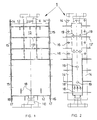
- the flow container is designed in the form of a cubic box. This has a feed inlet 10 and a retentate outlet 11 on. Feed inlet and retentate outlet are arranged opposite each other on the two short end faces of the box-shaped flow container 1. The fluid to be pervaporated flows continuously through the container from the feed inlet to the retentate outlet.
- the two short end walls 12 are firmly connected, in particular welded, to the two front walls 13 on the front and rear of the container.
- the edges of the front walls 13 are each bent at right angles to a circumferential flange 14 in the area of their lateral limitation. These two flanges 14 form the contact surfaces for the long, lateral longitudinal end walls 15. These two longitudinal end walls 15 are releasably attached to the flanges 14 by means of screw connections 16 in a cover-like manner. A seal 17 is inserted in the overlap area of the longitudinal end walls 15 and the circumferential flanges 14. To reinforce the large front surfaces 13, grid-shaped stiffening ribs 13 'are welded on. These stiffening ribs can only be seen in the upper area in FIG. 1 because the lower part of the flow container 1 is shown in section.
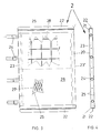
- the pervaporation chamber 2 already mentioned is shown in detail in FIGS. 3 and 4.
- the pervaporation chamber 2 comprises a frame construction 20, the upper and lower strips 21 of which are each provided with a holding comb 22. These holding combs 22 are dimensioned such that they can be inserted into the incisions 18 ′ in the supports 18 in the flow container 1.
- One longitudinal bar 23 is provided with inlet connection 24, while the opposite longitudinal bar 23 'is completely closed.
- Carrier plates 25 are arranged within the frame construction, sealingly connected to the strips 22, 23 and 23 ', and are covered with a permselective membrane 26 on the retentate side. This membrane is partially broken through in FIG. 3, so that you can see the perforation 27 in the support plates 25.
- carrier surfaces can be used which consist either of expanded metal, metal mesh or sintered synthetic, ceramic or metallic material with sufficient porosity.
- a pressure-absorbing grid 28 is inserted between the two support surfaces 25, support plates perforated in FIG. 3. This is essential to keep the gap width between a heating chamber and the adjacent pervaporation chamber as constant as possible, so that the flow conditions of the retentate in the gap are as constant as possible.
- the permeate or the permeate vapor is drawn off via the outlet connection 24. The condensation of the permeate only takes place outside the module according to the invention.
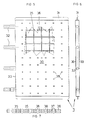
- a heating chamber of the module according to the invention is shown in detail in FIGS. 5-7. It consists of two metal sheets which are directly connected to one another at the longitudinal edges and which are likewise shaped and welded to a holding comb 31 at the upper and lower edges, which can be inserted into the incisions 18 ′ of the comb-like supports 18.
- inlet and outlet connections 32 are provided, which serve to guide the heating medium.
- the absolutely flat course of the sheets 30 is extremely important, in order in turn to keep the gap width to the adjacent pervaporation chamber the same. Therefore, there is a tensile force in the heating chamber 3 receiving, grid-shaped grate 34. This consists of crosswise laid longitudinal and transverse webs 36.
- the webs are provided with flow openings 37.
- the transverse webs 36 additionally have cams 38 which are at least as high as the sheets 30 are thick.
- cams 38 which are at least as high as the sheets 30 are thick.
- punchings 39 are provided in the metal sheets, in which the cams fit in a form-fitting manner.
- the cams must be kept sealed in the punchings.
- This special design of the individual chambers enables a very narrow gap to be created between the neighboring chambers. The gap between the two outermost heating chambers and the front walls 13 of the flow container can go to zero. This eliminates the need for a special line for the fluid to be pervaporated. In this way, a relatively simple module with high efficiency and excellent maintenance properties is realized.
Landscapes
- Engineering & Computer Science (AREA)
- Chemical & Material Sciences (AREA)
- Water Supply & Treatment (AREA)
- Chemical Kinetics & Catalysis (AREA)
- Analytical Chemistry (AREA)
- General Chemical & Material Sciences (AREA)
- Oil, Petroleum & Natural Gas (AREA)
- Separation Using Semi-Permeable Membranes (AREA)
- Preparation Of Compounds By Using Micro-Organisms (AREA)
- Pharmaceuticals Containing Other Organic And Inorganic Compounds (AREA)
- Medicines Containing Material From Animals Or Micro-Organisms (AREA)
- External Artificial Organs (AREA)
Abstract
Description
Die Pervaporation ist ein Membrantrennverfahren, mittels dem ein oder mehrere Anteile eines Fluidgemisches mittels Permeation abgetrennt wird. Durch die permselektive Membran, dessen eine Seite von der Flüssigkeit überströmt wird, diffundiert eine Komponente bevorzugt im Vergleich zu den anderen Komponenten. Die hindurch diffundierte Flüssigkeit ist das Permeat, während die Restflüssigkeit als Retentat bezeichnet wird. Auf der Permeatseite der Membran wird üblicherweise ein Vakuum angelegt, welches zur Verdampfung des Permeats führt.Pervaporation is a membrane separation process by means of which one or more portions of a fluid mixture are separated by means of permeation. One component diffuses through the permselective membrane, one side of which the liquid flows over, preferably in comparison to the other components. The liquid diffused through is the permeate, while the remaining liquid is called retentate. A vacuum is usually applied to the permeate side of the membrane, which leads to evaporation of the permeate.
Die Pervaporation wird durch Wärmezufuhr verbessert, weil hierdurch der Diffusionsvorgang beschleunigt wird, weil ferner die Verdampfung des Permeats in der Pervaporationskammer erleichtert wird, und weil schliesslich der Wärmeverlust durch Verdampfungsenthalpie kompensiert wird. Dabei ist die Homogenität der Temperaturverteilung äusserst wichtig.The pervaporation is improved by the addition of heat because this accelerates the diffusion process, because it also facilitates the evaporation of the permeate in the pervaporation chamber and because the heat loss is finally compensated for by the enthalpy of vaporization. The homogeneity of the temperature distribution is extremely important.
Aus der GB-A-938'127 ist ein Modul zur Durchführung der Pervaporation von Fluiden gemäss Oberbegriff des Patentanspruches bekannt. Dieses Modul ist besonders geeignet zur Anreicherung von Uran mit dem Isotop 235 mittels Diffusion. Entsprechend ist hier die Temperaturführung von geringerer Bedeutung als beispielsweise bei der Pervaporation in chemischen Verfahrensanlagen bei denen die Reinheit eines Fluids erhöht werden soll. Folglich arbeitet das bekannte Modul ohne Heizkammern.From GB-A-938'127 a module for performing the pervaporation of fluids is known according to the preamble of the claim. This module is particularly suitable for the enrichment of uranium with the isotope 235 by means of diffusion. Accordingly, the temperature control is of less importance here than, for example, in pervaporation in chemical process plants in which the purity of a fluid is to be increased. Consequently, the known module works without heating chambers.
Ein Modul, welches zusätzlich noch eine Heizkammer aufweist, ist aus der JP-A-63-59310 bekannt. Hier werden zwei Durchflussräume, welche einerseits von zwei permeablen Membranen und andererseits von einer Heizplatte begrenzt sind, gebildet und die Retentatseite der Membran gekühlt. Dies erlaubt jedoch, in der zu pervaporierenden Flüssigkeit keine gleichmässige Temperaturverteilung. Zudem ergibt eine solche Bauweise ein ungünstiges Verhältnis von der Baugrösse zur hindurchzuführenden Flüssigkeitsmenge.A module which additionally has a heating chamber is known from JP-A-63-59310. Here two flow spaces, which are bounded on the one hand by two permeable membranes and on the other hand by a heating plate, are formed and the retentate side of the membrane is cooled. However, this does not allow a uniform temperature distribution in the liquid to be pervaporated. In addition, such a construction results in an unfavorable ratio of the size to the amount of liquid to be passed through.
Auch die EP-A-0'118'760 und die US-A-3'695'444 offenbaren Module, die einen sandwichartigen Aufbau aus aneinander anliegenden, sich gegenseitig begrenzenden Heizkammern, Pervaporationskammern und Retentatkammern. Solche Module lassen sich sehr kompakt herstellen, sind jedoch nur für geringe Durchflussmengen geeignet und durch die mäandernden Fliesswege durch eine Folge von Kammern mit einem hohen Fliesswiderstand behaftet.EP-A-0'118'760 and US-A-3'695'444 also disclose modules which have a sandwich-like structure of mutually adjacent, mutually delimiting heating chambers, pervaporation chambers and retentate chambers. Such modules can be manufactured very compactly, but are only suitable for small flow rates and due to the meandering flow paths through a series of chambers with a high flow resistance afflicted.
Prinzipiell denselben Aufbau hat auch das Modul gemäss der EP-A-0'164'326. Der Unterschied ist hier lediglich, dass die jeweils benachbarten Kammern nicht plattenförmig sukzessiv nebeneinander, sondern sind konzentrisch ineinander geschachtelt.In principle, the module according to EP-A-0'164'326 has the same structure. The only difference here is that the adjacent chambers are not successively next to each other in the form of plates, but are nested concentrically one inside the other.
Die vorliegende Erfindung hat sich daher zur Aufgabe gestellt, ein Modul, gemäss Oberbegriff des Patentanspruches, so zu verbessern, dass ein hoher Flüssigkeitsdurchsatz in Bezug auf das Volumen des Moduls bei optimaler Temperaturverteilung ermöglicht wird.The object of the present invention is therefore to improve a module in accordance with the preamble of the patent claim in such a way that a high liquid throughput in relation to the volume of the module with an optimal temperature distribution is made possible.
Diese Aufgabe löst ein Modul mit den Merkmalen des Patentanspruches 1. Eine solche Anordnung erlaubt eine dichte Packung von abwechslungsweise Heizkammern und Pervaporationskammern, die berührungsfrei im Durchlaufbehältnis gehalten sind, was eine gleichmässige Strömung der Flüssigkeit bewirkt, eine optimale Temperaturverteilung ermöglicht und eine hohe Durchsatzmenge erlaubt.This object is achieved by a module with the features of
Eine besonders vorteilhafte Ausgestaltung, welche preiswert zu fertigen und optimal in der Montage und im Unterhalt ist, beschreibt Anspruch 2. Weil von einer Seite die Heizkammern und von der anderen Seite die Pervaporationskammern, die kammartig zueinander im Durchströmungsbehältnis liegen, zugänglich sind und daher ausgewechselt werden können.
Für die exakte Lagerung der Kammern, relativ zueinander, ist es von Vorteil im Durchlaufbehältnis kammartige Stützen anzubringen.For the exact storage of the chambers, relative to each other, it is advantageous to attach comb-like supports in the flow container.
Die Ausgestaltung nach Anspruch 4, garantiert den verformungsfreien Verlauf aller Wände des Durchlaufbehältnisses, wodurch exakte Strömungsverhältnisse erst gesichert sind.
Dasselbe wird auch durch die besondere Gestaltung der Pervaporationskammern und Heizkammern gemäss Anspruch 5, beziehungsweise 6 erreicht, da die entsprechende Roste Verformungen durch Ueberdruck beziehungsweise Unterdruck in den entsprechenden Kammern aufgefangen werden können.
Auch die Anbringung mehrerer Einlass- und Auslassanschlüsse an den Heiz- und Pervaporationskammern führt zu einer Verbesserung der Strömungs- und Temperaturführungsverhältnisse. Die Gestaltung des erfindungsgemässen Moduls ist nicht auf kubische Formen des Durchströmungsbehältnisses begrenzt, was die Lösung gemäss Anspruch 9 aufzeigt.The embodiment according to claim 4 guarantees the deformation-free course of all walls of the flow container, whereby exact flow conditions are only ensured.
The same is achieved by the special design of the pervaporation chambers and heating chambers according to claims 5 and 6, respectively, since the corresponding grate deformations can be absorbed by overpressure or underpressure in the corresponding chambers.
The attachment of several inlet and outlet connections to the heating and pervaporation chambers also leads to an improvement in the flow and temperature control conditions. The design of the module according to the invention is not limited to cubic shapes of the flow-through container, which shows the solution according to claim 9.
In der anliegenden Zeichnung sind die einzelnen Teile einer bevorzugten Lösung des erfindungsgemässen Moduls zur Pervaporation von Fluiden dargestellt und in der nachfolgenden Beschreibung erläutert.In the accompanying drawing, the individual parts of a preferred solution of the module according to the invention for pervaporation of fluids are shown and explained in the following description.
Es zeigt:
Figur 1- ein Durchlaufbehältnis in der Aufsicht und teilweise ins Schnitt, sowie
Figur 2- in der Seitenansicht und teilweise in Schnitt;
Figur 3- einer Pervaporationskammer in der Aufsicht und
- Figur 4
- in der Seitenansicht;
- Figur 5
- eine Heizkammer in der Aufsicht und
- Figur 6
- in der Seitensicht, sowie
- Figur 7
- einen in den Heizkammern zuliegen kommender Rost in der Seitenansicht.
- Figure 1
- a flow container in supervision and partly in section, as well
- Figure 2
- in side view and partly in section;
- Figure 3
- a pervaporation chamber under supervision and
- Figure 4
- in the side view;
- Figure 5
- a heating chamber under supervision and
- Figure 6
- in the side view, as well
- Figure 7
- a side view of a grate coming in the heating chambers.
Das erfindungsgemässe Modul zur Durchführung der Pervaporation von Fluiden weist drei wesentliche Bauteile auf, nämlich ein Durchlaufbehältnis 1, in dem eine oder mehrere Pervaporationskammer 2, beziehungsweise -Kammern und mehrere Heizkammern 3 angeordnet sind. In der einfachsten Form der Ausgestaltung ist im Durchlaufbehältnis 1 eine Pervaporationskammer 2, welche zwischen zwei Heizkammern 3 gelagert ist, vorgesehen. Dabei hat das Durchlaufbehältnis die Form eines flachen, quaderförmigen Kastens und die verschiedenen Kammern 2, 3 haben die Gestalt von Platten. Eine solche Ausführung ist in der Zeichung im Detail dargestellt.The module according to the invention for performing the pervaporation of fluids has three essential components, namely a
Die Erfindung begrenzt sich jedoch nicht auf eine solche Ausführungsform. Beispielsweise könnte das Durchlaufbehältnis auch die Gestalt eines Zylinders haben. In einer solchen Ausführung lassen sich dann die plattenförmigen Pervaporations- und Heizkammern alternierend und radial verlaufend, sternförmig nebeneinander angeordnet sein. Bei einer solchen Ausführung, die in der Zeichnung nicht dargestellt ist, lassen sich, beispielsweise alle Heizkammern oder alle Pervaporationskammern an einem Achsialträger angeordnet sein und über diese zentralgespiesen, beziehungsweise mit einer Vakuumpumpe in Verbindung stehen. Die Zylinderwand des Durchlaufbehälters kann dann als Träger der anderen Kammern dienen. Nachfolgend wird auf eine solche Ausführung nicht weiter eingegangen, weil die Gestalt, insbesondere der Kammern und deren relative Anordnung zueinander, unbeeinflusst bleibt. Lediglich mussten die Kammern von der Zylinderachse zur Zylinderwand in der Dicke zunehmend sein, damit die Spalten zwischen den Kammern überall gleich sind und das Fluid überall gleichmässig durchströmt.
In der Ausführung gemäss den Figuren 1 und 2 ist das Durchlaufbehältnis in der Form eines kubischen Kastens gestaltet. Dieser weist einen Feedeingang 10 und einen Retentatausgang 11 auf. Feedeingang und Retentatausgang sind an den beiden kurzen Stirnseiten des kastenförmigen Durchlaufbehältnisses 1 einander gegenüberliegend angeordnet. Das zu pervaporierende Fluid strömt kontinuierlich durch das Behältnis vom Feedeingang zum Retentatausgang.
Die beiden kurzen Stirnwände 12 sind mit den beiden Frontwänden 13, auf der Vorder- und Rückseite des Behältnisses, fest verbunden, insbesondere verschweisst. Die Ränder der Frontwände 13 sind im Bereich ihrer seitlichen Begrenzung je zu einem umlaufenden Flansch 14 rechtwinklig abgebogen. Diese beiden Flansche 14 bilden die Anlageflächen für die langen, seitlichen Längsstirnwände 15. Diese beiden Längsstirnwände 15 sind deckelartig auf die Flanschen 14 mittels Schraubverbindungen 16 lösbar befestigt. In dem Ueberlappungsbereich der Längsstirnwände 15 und den umlaufenden Flanschen 14 ist eine Dichtung 17 eingelegt. Zur Verstärkung der grossflächigen Frontflächen 13 sind gitterförmige Versteifungsrippen 13' aufgeschweisst. Diese Versteifungsrippen sind nur im oberen Bereich in der Figur 1 ersichtlich, weil der untere Teil des Durchlaufbehältnisses 1 im Schnitt dargestellt ist.
Im kastenförmigen Durchlaufbehältnis 1 sind unten mehrere parallele, kammartige Stützen 18 eingeschweisst, in welche die noch zu beschreibenden Pervaporationskammern 2 und Heizkammern 3 gehalten werden. Im dargestellten Beispiel sind in den kammartigen Stützen 18 drei Einschnitte 18' eingelassen, zur Aufnahme einer mittigen Pervaporationskammer und zwei äussere Heizkammern (welche in den Figuren 1 und 2 nicht dargestellt sind).
Entsprechend sind in den lösbaren Längsstirnwänden 15 Ein- und Auslassöffnungen 19 eingelassen. Um eine möglichst gleichmässige Temperaturverteilung zu erreichen, sind pro Kammer zwei Ein-, beziehungsweise Auslassöffnungen 19 vorgesehen. Dabei sind die Ein- und Auslassöffnungen für die Pervaporationskammer 2, in der eine deckelartige Längsstirnwand und für die beiden Heizkammern in der anderen Längsstirnwand eingelassen. Dies erlaubt die Heizkammern an der einen und die Pervaporationskammer an der anderen Längsstirnwand zu befestigen, so dass hierdurch zwei Einschubelemente entstehen. Dies ist für den Unterhalt des Moduls besonders vorteilhaft.
Die bereits genannte Pervaporationskammer 2 ist in den Figuren 3 und 4 im Detail dargestellt. Die Pervaporationskammer 2 umfasst eine Rahmenkonstruktion 20, deren obere und untere Leiste 21 je mit einem Haltekamm 22 versehen sind. Diese Haltekämme 22 sind so dimsioniert, dass sie in die Einschnitte 18' in den Stützen 18 im Durchlaufbehältnis 1 einführbar sind. Die eine Längsleiste 23 ist mit Einlassstutzen 24 versehen, während die gegenüberliegende Längsleiste 23' vollständig geschlossen ist.
Innerhalb der Rahmenkonstruktion, mit den Leisten 22,23 und 23' dichtend verbunden sind Trägerbleche 25 angeordnet, die auf der Retentatseite mit einer permselektiven Membran 26 belegt sind. In der Figur 3 ist diese Membran teilweise durchbrochen, so dass man die Lochung 27 in den Trägeblechen 25 erkennen kann. Allgemein können statt Trägerbleche Trägerflächen dienen, die entweder aus Streckmetall, Metallgewebe oder gesintertem synthetischem, keramischem oder metallischem Material mit einer genügenden Porösität bestehen.
Zwischen den beiden Trägerflächen 25, in der Figur 3 gelochte Trägerbleche, ist ein Druck aufnehmendes Gitter 28 eingelegt. Dies ist wesentlich um die Spaltbreite zwischen einer Heizkammer und der benachbarten Pervaporationskammer möglichst gleich zu halten, so dass die Strömungsverhältnisse des Retentates im Spalt möglichst gleichbleibend sind.
Ueber die Aulassstutzen 24 wird das Permeat, beziehungsweise der Permeatdampf abgesogen. Die Kondensation des Permeates erfolgt erst ausserhalb des erfindungsgemässen Moduls.However, the invention is not limited to such an embodiment. For example, the flow container could also have the shape of a cylinder. In such an embodiment, the plate-shaped pervaporation and heating chambers can then be arranged alternately and radially in a star shape next to one another. In such an embodiment, which is not shown in the drawing, it is possible, for example, to arrange all the heating chambers or all the pervaporation chambers on an axial carrier and to supply them centrally or to connect them to a vacuum pump. The cylinder wall of the flow container can then serve as a carrier for the other chambers. Such an embodiment will not be discussed further below because the shape, in particular of the chambers and their relative arrangement to one another, remains unaffected. All that had to be done was to increase the thickness of the chambers from the cylinder axis to the cylinder wall so that the gaps between the chambers are the same everywhere and the fluid flows uniformly everywhere.
In the embodiment according to Figures 1 and 2, the flow container is designed in the form of a cubic box. This has a
The two
In the box-shaped
Correspondingly, 15 inlet and
The
A pressure-absorbing
The permeate or the permeate vapor is drawn off via the
In den Figuren 5-7 ist eine Heizkammer des erfindungsgemässen Moduls im Detail dargestellt. Sie besteht aus zwei Blechen, die an den Längskanten direkt miteinander verbunden sind und an der oberen und unteren Kante ebenfalls zu einem Haltekamm 31 geformt und verschweisst sind, die in die Einschnitte 18' der kammartigen Stützen 18 einführbar sind. In der einen Längsstirnwand 33 sind Ein- und Auslassstutzen 32 vorgesehen, die der Führung des Heizmediums dienen. Auch hier ist der absolut plane Verlauf der Bleche 30 eminent wichtig, um wiederum die Spaltbreite zur benachbarten Pervaporationskammer gleich zu halten. Deshalb ist in der Heizkammer 3 ein Zugkräfte aufnehmender, gitterförmiger Rost 34. Dieser besteht aus kreuzweise verlegten Längs- 35 und Querstege 36. Die Stege sind mit Durchströmungsöffnungen 37 versehen. Die Querstege 36 weisen zusätzlich Nocken 38 auf, die mindestens so hoch, wie die Bleche 30 dick sind. Entsprechend dem Raster der Nocken 38 sind in den Blechen 30 Stanzungen 39 vorhanden, in denen die Nocken formschlüssig passen. Selbstverständlich müssen die Nocken in den Stanzungen dichtend gehalten sein.
Durch diese spezielle Konstruktion der einzelnen Kammern kann ein sehr schmaler Spalt zwischen der benachbarten Kammern realisiert werden. Der Spalt zwischen den beiden äussersten Heizkammern und den Frontwänden 13 des Durchflussbehältnisses kann gegen Null gehen. Somit erübrigt sich eine spezielle Leitung des zu pervaporierenden Fluids. So wird ein relativ einfaches Modul mit hoher Effizienz und ausgezeichneten Wartungseigenschaften realisiert.A heating chamber of the module according to the invention is shown in detail in FIGS. 5-7. It consists of two metal sheets which are directly connected to one another at the longitudinal edges and which are likewise shaped and welded to a holding
This special design of the individual chambers enables a very narrow gap to be created between the neighboring chambers. The gap between the two outermost heating chambers and the
Claims (9)
Applications Claiming Priority (2)
| Application Number | Priority Date | Filing Date | Title |
|---|---|---|---|
| CH1720/92 | 1992-05-27 | ||
| CH1720/92A CH685331A5 (en) | 1992-05-27 | 1992-05-27 | Module to perform the pervaporation of fluids. |
Publications (2)
| Publication Number | Publication Date |
|---|---|
| EP0572355A1 true EP0572355A1 (en) | 1993-12-01 |
| EP0572355B1 EP0572355B1 (en) | 1996-04-24 |
Family
ID=4217028
Family Applications (1)
| Application Number | Title | Priority Date | Filing Date |
|---|---|---|---|
| EP93810375A Expired - Lifetime EP0572355B1 (en) | 1992-05-27 | 1993-05-21 | Module for executing the pervaporation of fluids |
Country Status (9)
| Country | Link |
|---|---|
| US (1) | US5389255A (en) |
| EP (1) | EP0572355B1 (en) |
| JP (1) | JPH0686917A (en) |
| AT (1) | ATE137135T1 (en) |
| CH (1) | CH685331A5 (en) |
| DE (1) | DE59302324D1 (en) |
| DK (1) | DK0572355T3 (en) |
| ES (1) | ES2086916T3 (en) |
| FI (1) | FI932016A7 (en) |
Cited By (1)
| Publication number | Priority date | Publication date | Assignee | Title |
|---|---|---|---|---|
| WO2000053292A1 (en) * | 1999-03-10 | 2000-09-14 | Metallgesellschaft Ag | Method and device of separating substance mixtures in liquid and/or vapour form by pervaporation and/or vapour permeation |
Families Citing this family (7)
| Publication number | Priority date | Publication date | Assignee | Title |
|---|---|---|---|---|
| DE19957641C1 (en) * | 1999-11-30 | 2001-06-13 | Membraflow Gmbh & Co Kg Filter | Filter membrane module with integrated heat exchanger |
| US6306307B1 (en) | 2000-03-07 | 2001-10-23 | Fielding Chemical Technologies, Inc. | Pervaporation apparatus and method |
| US7423192B2 (en) * | 2003-11-18 | 2008-09-09 | Exxonmobil Research And Engineering Company | Process and system for blending components obtained from a stream |
| US7318898B2 (en) * | 2003-11-18 | 2008-01-15 | Exxonmobil Research And Engineering Company | Polymeric membrane wafer assembly and method |
| AU2004291500A1 (en) * | 2003-11-18 | 2005-06-02 | Exxonmobil Research And Engineering Company | Method and apparatus for separating aromatic hydrocarbons in a non-adiabatic membrane system |
| US7303681B2 (en) * | 2003-11-18 | 2007-12-04 | Exxonmobil Research And Engineering Company | Dynamic membrane wafer assembly and method |
| JP5391307B2 (en) | 2012-05-14 | 2014-01-15 | ファナック株式会社 | Safety door device for injection molding machine |
Citations (3)
| Publication number | Priority date | Publication date | Assignee | Title |
|---|---|---|---|---|
| US3695444A (en) * | 1968-12-24 | 1972-10-03 | Ionics | Membrane support |
| EP0118760A2 (en) * | 1983-02-12 | 1984-09-19 | Gkss-Forschungszentrum Geesthacht Gmbh | Device for the separation of solutions by pervaporation |
| EP0164326A2 (en) * | 1984-06-07 | 1985-12-11 | Svenska Utvecklingsaktiebolaget(Su) Swedish National Development Co. | System for diaphragm distillation |
Family Cites Families (8)
| Publication number | Priority date | Publication date | Assignee | Title |
|---|---|---|---|---|
| NL257545A (en) * | 1959-11-04 | |||
| US3398091A (en) * | 1966-08-09 | 1968-08-20 | Ionics | Membrane separation apparatus and process |
| US3608610A (en) * | 1969-10-01 | 1971-09-28 | Ionics | Apparatus for evaporative separation of liquids through microporous panels |
| DE2911508A1 (en) * | 1978-03-28 | 1979-10-04 | Kuraray Co | FLUID TREATMENT DEVICE |
| DE3441190A1 (en) * | 1984-11-10 | 1986-05-15 | Metallgesellschaft Ag, 6000 Frankfurt | DEVICE FOR SEPARATING LIQUID MIXTURES BY PERVAPORATION |
| JPS6359310A (en) * | 1986-08-29 | 1988-03-15 | Nitto Electric Ind Co Ltd | Thermo-pervaporation device |
| JPS6369506A (en) * | 1986-09-12 | 1988-03-29 | Mitsui Eng & Shipbuild Co Ltd | Osmosis and vaporization membrane module |
| JPS63151305A (en) * | 1986-12-15 | 1988-06-23 | Mitsui Eng & Shipbuild Co Ltd | Osmotic evaporation membrane module |
-
1992
- 1992-05-27 CH CH1720/92A patent/CH685331A5/en not_active IP Right Cessation
-
1993
- 1993-05-05 FI FI932016A patent/FI932016A7/en unknown
- 1993-05-14 JP JP5112990A patent/JPH0686917A/en active Pending
- 1993-05-19 US US08/064,512 patent/US5389255A/en not_active Expired - Fee Related
- 1993-05-21 EP EP93810375A patent/EP0572355B1/en not_active Expired - Lifetime
- 1993-05-21 AT AT93810375T patent/ATE137135T1/en not_active IP Right Cessation
- 1993-05-21 ES ES93810375T patent/ES2086916T3/en not_active Expired - Lifetime
- 1993-05-21 DE DE59302324T patent/DE59302324D1/en not_active Expired - Fee Related
- 1993-05-21 DK DK93810375.1T patent/DK0572355T3/en active
Patent Citations (3)
| Publication number | Priority date | Publication date | Assignee | Title |
|---|---|---|---|---|
| US3695444A (en) * | 1968-12-24 | 1972-10-03 | Ionics | Membrane support |
| EP0118760A2 (en) * | 1983-02-12 | 1984-09-19 | Gkss-Forschungszentrum Geesthacht Gmbh | Device for the separation of solutions by pervaporation |
| EP0164326A2 (en) * | 1984-06-07 | 1985-12-11 | Svenska Utvecklingsaktiebolaget(Su) Swedish National Development Co. | System for diaphragm distillation |
Non-Patent Citations (1)
| Title |
|---|
| PATENT ABSTRACTS OF JAPAN vol. 012, no. 299 (C-520)15. August 1988 & JP-A-63 069 506 ( MITSUI ENG & SHIPBUILD CO LTD ) 29. März 1988 * |
Cited By (1)
| Publication number | Priority date | Publication date | Assignee | Title |
|---|---|---|---|---|
| WO2000053292A1 (en) * | 1999-03-10 | 2000-09-14 | Metallgesellschaft Ag | Method and device of separating substance mixtures in liquid and/or vapour form by pervaporation and/or vapour permeation |
Also Published As
| Publication number | Publication date |
|---|---|
| ATE137135T1 (en) | 1996-05-15 |
| FI932016A7 (en) | 1993-11-28 |
| ES2086916T3 (en) | 1996-07-01 |
| JPH0686917A (en) | 1994-03-29 |
| CH685331A5 (en) | 1995-06-15 |
| DK0572355T3 (en) | 1996-06-03 |
| DE59302324D1 (en) | 1996-05-30 |
| EP0572355B1 (en) | 1996-04-24 |
| FI932016A0 (en) | 1993-05-05 |
| US5389255A (en) | 1995-02-14 |
Similar Documents
| Publication | Publication Date | Title |
|---|---|---|
| DE2556210C3 (en) | Device for water desalination by reverse osmosis | |
| DE19860253C1 (en) | Stacked modular membrane unit used for the separation of hydrogen from a mixture of gases for supply to a fuel cell | |
| DE2525972C2 (en) | Membrane element and device for carrying out membrane filtration | |
| DE2134752A1 (en) | Support plate for the membranes of a dialyzer, especially for hemodialysis | |
| EP0214496A2 (en) | Apparatus for separating mixtures by pervaporization | |
| WO1998030316A1 (en) | Device for filtering and separating flowing fluids | |
| DE2060178B2 (en) | Grid exchange packing for columns | |
| DE2209116C3 (en) | Reverse osmosis or ultrafiltration device | |
| DE2406077C2 (en) | Diffusion device, | |
| EP0891221A1 (en) | Membrane module for a membrane separation system, its use and process for producing the same | |
| DE1501618C3 (en) | Heat exchanger | |
| WO1997020621A1 (en) | Device for filtering and separating flow media | |
| WO2013013785A1 (en) | Membrane module for organophile pervaporation | |
| EP1879674A1 (en) | Micro-evaporator | |
| EP0572355B1 (en) | Module for executing the pervaporation of fluids | |
| DE2722288B2 (en) | Plate heat exchanger, in which plates following one another at a distance have through openings for the one heat exchange medium | |
| DE2508867B2 (en) | Device for heat or material exchange, which consists of several exchange spaces formed by parallel plates | |
| EP0231558B1 (en) | Separation apparatus | |
| DE2304702A1 (en) | DEVICE FOR DISCONNECTING LIQUIDS INTO TWO QUANTITIES BY USING SEMIPERMEABLES | |
| DE2814326A1 (en) | POROESE SUPPORT FOR USE IN A DIVIDER WITH HOLLOW FIBER | |
| DE2518614A1 (en) | MEMBRANE SEPARATOR | |
| EP1360984B1 (en) | Apparatus for separating a component from a gas mixture or a liquid mixture | |
| WO1992000129A1 (en) | Column body to take plate-type heat exchangers | |
| DE2652605A1 (en) | MEMBRANE MODULE FOR REVERSE OSMOSIS OR ULTRAFILTRATION | |
| DE2121963C3 (en) | Plate evaporator with falling liquid film |
Legal Events
| Date | Code | Title | Description |
|---|---|---|---|
| PUAI | Public reference made under article 153(3) epc to a published international application that has entered the european phase |
Free format text: ORIGINAL CODE: 0009012 |
|
| AK | Designated contracting states |
Kind code of ref document: A1 Designated state(s): AT BE CH DE DK ES FR GB IT LI NL SE |
|
| 17P | Request for examination filed |
Effective date: 19940520 |
|
| 17Q | First examination report despatched |
Effective date: 19950818 |
|
| GRAH | Despatch of communication of intention to grant a patent |
Free format text: ORIGINAL CODE: EPIDOS IGRA |
|
| ITF | It: translation for a ep patent filed | ||
| GRAA | (expected) grant |
Free format text: ORIGINAL CODE: 0009210 |
|
| AK | Designated contracting states |
Kind code of ref document: B1 Designated state(s): AT BE CH DE DK ES FR GB IT LI NL SE |
|
| REF | Corresponds to: |
Ref document number: 137135 Country of ref document: AT Date of ref document: 19960515 Kind code of ref document: T |
|
| REG | Reference to a national code |
Ref country code: CH Ref legal event code: NV Representative=s name: PATENTANWALTSBUERO FELDMANN AG |
|
| REF | Corresponds to: |
Ref document number: 59302324 Country of ref document: DE Date of ref document: 19960530 |
|
| REG | Reference to a national code |
Ref country code: DK Ref legal event code: T3 |
|
| GBT | Gb: translation of ep patent filed (gb section 77(6)(a)/1977) |
Effective date: 19960514 |
|
| REG | Reference to a national code |
Ref country code: ES Ref legal event code: FG2A Ref document number: 2086916 Country of ref document: ES Kind code of ref document: T3 |
|
| ET | Fr: translation filed | ||
| PLBE | No opposition filed within time limit |
Free format text: ORIGINAL CODE: 0009261 |
|
| STAA | Information on the status of an ep patent application or granted ep patent |
Free format text: STATUS: NO OPPOSITION FILED WITHIN TIME LIMIT |
|
| 26N | No opposition filed | ||
| PGFP | Annual fee paid to national office [announced via postgrant information from national office to epo] |
Ref country code: SE Payment date: 19980518 Year of fee payment: 6 |
|
| PGFP | Annual fee paid to national office [announced via postgrant information from national office to epo] |
Ref country code: BE Payment date: 19980525 Year of fee payment: 6 |
|
| PGFP | Annual fee paid to national office [announced via postgrant information from national office to epo] |
Ref country code: ES Payment date: 19980526 Year of fee payment: 6 |
|
| PGFP | Annual fee paid to national office [announced via postgrant information from national office to epo] |
Ref country code: AT Payment date: 19980528 Year of fee payment: 6 |
|
| PGFP | Annual fee paid to national office [announced via postgrant information from national office to epo] |
Ref country code: DK Payment date: 19980529 Year of fee payment: 6 |
|
| PG25 | Lapsed in a contracting state [announced via postgrant information from national office to epo] |
Ref country code: AT Free format text: LAPSE BECAUSE OF NON-PAYMENT OF DUE FEES Effective date: 19990521 |
|
| PG25 | Lapsed in a contracting state [announced via postgrant information from national office to epo] |
Ref country code: SE Free format text: LAPSE BECAUSE OF NON-PAYMENT OF DUE FEES Effective date: 19990522 Ref country code: ES Free format text: THE PATENT HAS BEEN ANNULLED BY A DECISION OF A NATIONAL AUTHORITY Effective date: 19990522 |
|
| PG25 | Lapsed in a contracting state [announced via postgrant information from national office to epo] |
Ref country code: DK Free format text: LAPSE BECAUSE OF NON-PAYMENT OF DUE FEES Effective date: 19990531 Ref country code: BE Free format text: LAPSE BECAUSE OF NON-PAYMENT OF DUE FEES Effective date: 19990531 |
|
| BERE | Be: lapsed |
Owner name: KREBS & CO. A.G. Effective date: 19990531 |
|
| EUG | Se: european patent has lapsed |
Ref document number: 93810375.1 |
|
| REG | Reference to a national code |
Ref country code: DK Ref legal event code: EBP |
|
| REG | Reference to a national code |
Ref country code: GB Ref legal event code: IF02 |
|
| REG | Reference to a national code |
Ref country code: ES Ref legal event code: FD2A Effective date: 20020204 |
|
| PGFP | Annual fee paid to national office [announced via postgrant information from national office to epo] |
Ref country code: NL Payment date: 20020430 Year of fee payment: 10 |
|
| PGFP | Annual fee paid to national office [announced via postgrant information from national office to epo] |
Ref country code: GB Payment date: 20020502 Year of fee payment: 10 |
|
| PGFP | Annual fee paid to national office [announced via postgrant information from national office to epo] |
Ref country code: FR Payment date: 20020513 Year of fee payment: 10 |
|
| PG25 | Lapsed in a contracting state [announced via postgrant information from national office to epo] |
Ref country code: GB Free format text: LAPSE BECAUSE OF NON-PAYMENT OF DUE FEES Effective date: 20030521 |
|
| PG25 | Lapsed in a contracting state [announced via postgrant information from national office to epo] |
Ref country code: NL Free format text: LAPSE BECAUSE OF NON-PAYMENT OF DUE FEES Effective date: 20031201 |
|
| GBPC | Gb: european patent ceased through non-payment of renewal fee |
Effective date: 20030521 |
|
| PG25 | Lapsed in a contracting state [announced via postgrant information from national office to epo] |
Ref country code: FR Free format text: LAPSE BECAUSE OF NON-PAYMENT OF DUE FEES Effective date: 20040130 |
|
| NLV4 | Nl: lapsed or anulled due to non-payment of the annual fee |
Effective date: 20031201 |
|
| REG | Reference to a national code |
Ref country code: FR Ref legal event code: ST |
|
| PG25 | Lapsed in a contracting state [announced via postgrant information from national office to epo] |
Ref country code: IT Free format text: LAPSE BECAUSE OF NON-PAYMENT OF DUE FEES Effective date: 20050521 |
|
| PGFP | Annual fee paid to national office [announced via postgrant information from national office to epo] |
Ref country code: DE Payment date: 20060519 Year of fee payment: 14 |
|
| PGFP | Annual fee paid to national office [announced via postgrant information from national office to epo] |
Ref country code: CH Payment date: 20060825 Year of fee payment: 14 |
|
| REG | Reference to a national code |
Ref country code: CH Ref legal event code: PFA Owner name: KREBS & CO. AG Free format text: KREBS & CO. AG#CLARIDENSTRASSE 20#CH-8022 ZUERICH (CH) -TRANSFER TO- KREBS & CO. AG#CLARIDENSTRASSE 20#CH-8022 ZUERICH (CH) |
|
| REG | Reference to a national code |
Ref country code: CH Ref legal event code: PL |
|
| PG25 | Lapsed in a contracting state [announced via postgrant information from national office to epo] |
Ref country code: CH Free format text: LAPSE BECAUSE OF NON-PAYMENT OF DUE FEES Effective date: 20070531 Ref country code: LI Free format text: LAPSE BECAUSE OF NON-PAYMENT OF DUE FEES Effective date: 20070531 |
|
| PG25 | Lapsed in a contracting state [announced via postgrant information from national office to epo] |
Ref country code: DE Free format text: LAPSE BECAUSE OF NON-PAYMENT OF DUE FEES Effective date: 20071201 |