EP0572347A1 - Animal feeder - Google Patents
Animal feeder Download PDFInfo
- Publication number
- EP0572347A1 EP0572347A1 EP93500069A EP93500069A EP0572347A1 EP 0572347 A1 EP0572347 A1 EP 0572347A1 EP 93500069 A EP93500069 A EP 93500069A EP 93500069 A EP93500069 A EP 93500069A EP 0572347 A1 EP0572347 A1 EP 0572347A1
- Authority
- EP
- European Patent Office
- Prior art keywords
- sluice
- rod
- dispensing
- tubular body
- axle
- Prior art date
- Legal status (The legal status is an assumption and is not a legal conclusion. Google has not performed a legal analysis and makes no representation as to the accuracy of the status listed.)
- Granted
Links
Images

Classifications
-
- A—HUMAN NECESSITIES
- A01—AGRICULTURE; FORESTRY; ANIMAL HUSBANDRY; HUNTING; TRAPPING; FISHING
- A01K—ANIMAL HUSBANDRY; CARE OF BIRDS, FISHES, INSECTS; FISHING; REARING OR BREEDING ANIMALS, NOT OTHERWISE PROVIDED FOR; NEW BREEDS OF ANIMALS
- A01K5/00—Feeding devices for stock or game ; Feeding wagons; Feeding stacks
- A01K5/02—Automatic devices
- A01K5/0225—Gravity replenishment from a reserve, e.g. a hopper
- A01K5/0233—Gravity replenishment from a reserve, e.g. a hopper dispensing by dosing means actively operated by the animal
-
- A—HUMAN NECESSITIES
- A01—AGRICULTURE; FORESTRY; ANIMAL HUSBANDRY; HUNTING; TRAPPING; FISHING
- A01K—ANIMAL HUSBANDRY; CARE OF BIRDS, FISHES, INSECTS; FISHING; REARING OR BREEDING ANIMALS, NOT OTHERWISE PROVIDED FOR; NEW BREEDS OF ANIMALS
- A01K5/00—Feeding devices for stock or game ; Feeding wagons; Feeding stacks
- A01K5/02—Automatic devices
- A01K5/0225—Gravity replenishment from a reserve, e.g. a hopper
-
- A—HUMAN NECESSITIES
- A01—AGRICULTURE; FORESTRY; ANIMAL HUSBANDRY; HUNTING; TRAPPING; FISHING
- A01K—ANIMAL HUSBANDRY; CARE OF BIRDS, FISHES, INSECTS; FISHING; REARING OR BREEDING ANIMALS, NOT OTHERWISE PROVIDED FOR; NEW BREEDS OF ANIMALS
- A01K1/00—Housing animals; Equipment therefor
- A01K1/02—Pigsties; Dog-kennels; Rabbit-hutches or the like
- A01K1/035—Devices for use in keeping domestic animals, e.g. fittings in housings or dog beds
-
- A—HUMAN NECESSITIES
- A01—AGRICULTURE; FORESTRY; ANIMAL HUSBANDRY; HUNTING; TRAPPING; FISHING
- A01K—ANIMAL HUSBANDRY; CARE OF BIRDS, FISHES, INSECTS; FISHING; REARING OR BREEDING ANIMALS, NOT OTHERWISE PROVIDED FOR; NEW BREEDS OF ANIMALS
- A01K29/00—Other apparatus for animal husbandry
Definitions
- the present invention relates to a feeder for livestock, principally an individual feeder for pigs.
- feeders all of which generally comprise a vertical tubular body forming a hopper with a dispensing valve whose output can be regulated, said valve being operated by the snout of the animal itself, the feeder additionally comprising a water supply valve which is also operated by the animal to mix the water with the feed if it should so desire, said mixture being produced in a lower plate joined to the tubular body.
- the object of the present invention is to solve these and other drawbacks by devising a dispensing valve which can be easily disassembled, has a hopper with a funnel-shaped bottom which has no gaps, a plate which is equally easy to disassemble and which rests directly on the floor.
- the feeder is provided with a visual indication to show the adjustment of the dispensing valve.
- a dispensing body made of plastic material is fixed vertically to a lower neck of the funnel-shaped bottom of the hopper and horizontally to the tubular body, said dispensing body forming an upper chamber which channels the feed and is connected to a lower dispensing chamber in which a piston operates, said piston forming an integral part of a metal sluice operated by the animal and hinged on said dispensing body.
- the sluice hinge axle can be disassembled from the dispensing body, said axle being kept in position by means of a spring pin which is fixed into an orifice of the lower neck of the hopper and through which said axle is fitted.
- the invention is further characterized in that the bottom of the dispensing chamber is curved corresponding to the curve which the piston traces with the sluice as it rotates about the axle of the hinge, whereby all the feed dispensed is sent to the plate without bits accumulating in said chamber to start rotting.
- the invention is further characterized by the constitution of the sluice end stop, which defines its rest position, and the dispensing valve adjustment means.
- the feeder is provided with means to enable the person in charge to manually adjust the dispensing valve with ease, without the need of special tools or equipment, said adjustment being carried out quickly and the resulting adjustment being clearly displayed by the position of the rod described at predetermined intervals.
- the means described comprise an eccentric control provided with a toothed edge which acts by engaging, between said teeth, the rounded upper end of the rod, said rod abutting elastically against said edge. In this way, by rotating the eccentric control in either one direction or the other the rod can be raised or lowered.
- the upper support which guides the rod consists of a small box where the eccentric control operates.
- the control extends from an upper curved slot in said box and is provided with an indicator which, as the control is rotated, points to the reference marks provided on the edge of said slot in correspondence with the various predetermined heights of the rod.
- the pig feeder comprises a vertical tubular body 1 forming an upper hopper 2 whose lower outlet is provided with an adjustable dispensing valve 3 from which the feed falls onto a plate 4 which is joined below to said surrounding tubular body 1.
- the hopper 2 consists of the upper part of the tubular body 1, the lower part closing in an asymmetric funnel with a lower rectangular opening 6 (figure 2) around which is formed a neck 7 (figure 3) to which the dispensing valve 3 is attached, the funnel being fixed to the tubular body at various points by nuts and bolts.
- Said valve comprises a dispensing body 8 consisting of a one-piece plastic moulding which is fixed vertically to the funnel 5 beneath its opening by means of bolts which pass through the holes 9 in said body and are coupled to the corresponding nuts located inside the holes 10 in the funnel.
- the dispensing body 8 is also fixed horizontally to the tubular body 1 by means of radial bolts which are coupled to nuts located inside the housings 11 provided in said body 8.
- the dispensing body forms an upper chamber 12 (Fig. 2) which channels the feed from the funnel 5 to a lower chamber 13 of said body where the feed is dispensed, the chamber comprising a frontal opening 14 and a rear opening 15.
- the frontal opening 14 houses a piston 16 which forms an integral part of a metal sluice 17 the upper part of which is hinged relative to the dispenser 8 by means of an axle 18, the upper part of said dispenser being horizontally provided with a pair of lateral tubular protuberances 19 into which the axle 18 is fitted, the sluice being attached to said axle by means of lateral lugs 20, each provided with holes 21, (Fig. 4).
- the axle is removably attached so that the dispensing body 8 can be disassembled, to which end said axle is fitted through a square orifice 22 in the neck 7 of the funnel where a U-shaped elastic spring clip 23 is fitted such that once the spring clip 23 has been removed, the other end of the axle 18 can be accessed through an orifice 24, which is smaller in diameter than the axle and which is provided in said neck, to push the axle through the orifice 25 in the tubular body through which said axle was previously inserted (figure 3).
- the animal operates the dispensing valve by pushing the sluice 17 with its snout as shown by the arrow F in figure 2. With this movement the piston 16 pushes the feed in the lower chamber 13 which then falls due to gravity onto the plate 4. The piston passes closely over the base 24 of said chamber, which is curved in correspondence with the curve which the piston traces as the sluice 17 moves about the axle 18.
- the sluice When the animal withdraws, the sluice returns due to gravity to its rest position which is determined by a lower protrusion 26 of the dispensing body 8 acting as a stop against a plate 25 joined transversally to both of the lower prolongations 27 and at the back to the perforated lugs 20 of the sluice 17 (figure 4).
- the amount of feed dispensed and falling onto the plate 4 when the sluice 17 is operated is determined by the lower end of a vertical rod 28 acting as a stop for the rear plate 25 of said sluice, said rod passing through the dispensing body via a hole 29 provided therein (figure 3) and being adjustable in height in the vertical position.
- the upper part of the rod 28 is guided by a support 30 fixed inside the wall of the tubular body 1 next to the upper opening 1', said support forming a horizontal plane with a threaded orifice 31 which acts as a nut into which the upper threaded part 32 of the rod 28 is screwed such that when it is rotated by means of an upper knob 33, the rod, and therefore its lower end, can be raised or lowered, thereby regulating the amount of travel of the sluice/piston assembly.
- wingnut 34 acting as a locknut which is screwed onto the rod 28 and which abuts against the support 30.
- These adjustment means are provided with a visual indicator of the position of the rod consisting of a bracket 35 which extends vertically upwards and forms part of the support 30, said bracket being provided with reference marks 36 which are at different heights (figure 5) and which are indicated by an indicating disc 37 screwed onto the rod 28.
- the plate 4 is joined to the tubular body in a simple way which enables it to be disassembled without the need of any tools.
- the plate is provided with a peripheral wall 38 whose external diameter corresponds to the internal diameter of the body 1, said wall being provided with an outwardly oriented lower flange 39 via which the plate rests on the floor, the lower opening of the tubular body being positioned on this flange.
- the plate is removably fixed to the tubular body by means of elastic tabs 40 which are provided on the wall (Fig. 6) and which are each located on a tongue 41 stamped out of said wall, each of said tabs fitting into orifices 42 provided in the lower part of the tubular body 1.
- the water supply valve 43 can also be operated by the animal if it wishes to eat moist feed, the animal being able to access the feed and the water via the lateral opening 44 in the tubular body 1.
- a radially arranged small flat box 45 is fixed to the inner part of the upper opening 1' of the vertical tubular body 1 of the feeder, said box being fixed to said body by means of two lateral wings 46 and 47 which are each provided with coplanar orifices 48 and 49 through which bolts 50 are inserted, passing through the tubular body 1 and a reinforcement plate 51 provided on the external face, said bolts being secured with the corresponding nuts 52.
- the two opposed faces of the upper part of said box 45 are each pressed and holes made therein to provide recesses 53 into which a transverse axle 54 is fitted.
- the control 55 which pivots about said axle and whose upper part projects through a curved slot 56, comprises an eccentric 57 with a toothed edge 58, the control actuating via said edge which presses on the rounded upper end 59 of the vertical rod 28 of which said box constitutes the upper guide support.
- the upper end of the rod 28 is guided within the box 45 by means of two opposing tabs 60 and 61 which have curved edges and which are each produced by stamping out parts 62 and 63 of the two opposing faces of the box.
- the rod 28 is elastically arranged against the toothed edge 58 of the control 55 by means of a spring 64 which is positioned on the rod, the upper part of said spring abutting a washer 65 fixed to a peripheral neck of the rod 28.
- the lower part of said spring abuts another washer 67 which is positioned freely on the rod 28 and which is fixed into lateral cut-outs 68 in the box 45.
- the curved slot 56 is pressed out giving rise to a part 69 on which a series of reference marks 70, for example numbers, are provided in correspondence with the various predetermined positions in height of the rod 28, said reference marks being pointed to by an indicator 71 to show the height chosen.
- a series of reference marks 70 for example numbers
Abstract
Description
- The present invention relates to a feeder for livestock, principally an individual feeder for pigs.
- Their exist various models of this kind of feeder, all of which generally comprise a vertical tubular body forming a hopper with a dispensing valve whose output can be regulated, said valve being operated by the snout of the animal itself, the feeder additionally comprising a water supply valve which is also operated by the animal to mix the water with the feed if it should so desire, said mixture being produced in a lower plate joined to the tubular body.
- Most of the dispensing valves which have been used until now consist of various metal parts joined together, increasing the cost of manufacture and making them very heavy. This, together with the pressure exerted by the animal to open them, cause them to come away from the surrounding body and the hopper, which consist of plastic material and cannot withstand such forces.
- Other drawbacks of the known feeders are due to the difficulty with which said valves are disassembled for routine cleaning and the fact that the bottom of the hopper is constructed along an inclined plane defining a number of lateral spaces next to the lower outlet where the feed can get stuck, accumulate and begin to rot, with harmful consequences for the animal.
- The object of the present invention is to solve these and other drawbacks by devising a dispensing valve which can be easily disassembled, has a hopper with a funnel-shaped bottom which has no gaps, a plate which is equally easy to disassemble and which rests directly on the floor.
- In addition, the feeder is provided with a visual indication to show the adjustment of the dispensing valve.
- In order to achieve these advantages a dispensing body made of plastic material is fixed vertically to a lower neck of the funnel-shaped bottom of the hopper and horizontally to the tubular body, said dispensing body forming an upper chamber which channels the feed and is connected to a lower dispensing chamber in which a piston operates, said piston forming an integral part of a metal sluice operated by the animal and hinged on said dispensing body.
- Another characteristic of the present feeder is the fact that the sluice hinge axle can be disassembled from the dispensing body, said axle being kept in position by means of a spring pin which is fixed into an orifice of the lower neck of the hopper and through which said axle is fitted.
- The invention is further characterized in that the bottom of the dispensing chamber is curved corresponding to the curve which the piston traces with the sluice as it rotates about the axle of the hinge, whereby all the feed dispensed is sent to the plate without bits accumulating in said chamber to start rotting.
- The invention is further characterized by the constitution of the sluice end stop, which defines its rest position, and the dispensing valve adjustment means.
- Furthermore the feeder is provided with means to enable the person in charge to manually adjust the dispensing valve with ease, without the need of special tools or equipment, said adjustment being carried out quickly and the resulting adjustment being clearly displayed by the position of the rod described at predetermined intervals.
- To achieve these advantages the means described comprise an eccentric control provided with a toothed edge which acts by engaging, between said teeth, the rounded upper end of the rod, said rod abutting elastically against said edge. In this way, by rotating the eccentric control in either one direction or the other the rod can be raised or lowered.
- The upper support which guides the rod consists of a small box where the eccentric control operates. The control extends from an upper curved slot in said box and is provided with an indicator which, as the control is rotated, points to the reference marks provided on the edge of said slot in correspondence with the various predetermined heights of the rod.
- These and other characteristics will become more clear from the detailed description which follows, with the help of a series of drawings showing some practical embodiments which represent only one non-limiting example of the scope of the present invention.
- In the drawings:
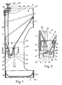
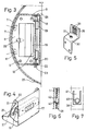
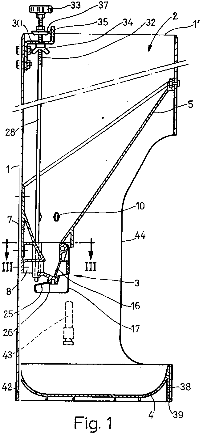
- Figure 1 shows a sectional elevation of the feeder assembly,
- figure 2 shows in elevated section a detail of the dispensing body when the piston being activated,
- figure 3 illustrates a sectional plan view of the feeder taken along the line III-III of figure 1,
- figure 4 represents a partially cut away perspective view of the metal sluice to which the piston is attached,
- figure 5 shows a perspective view of the bracket which is provided with reference marks to indicate the adjustment of the dispensing valve,
- figure 6 is a sectional elevation of a detail of the way in which the plate is joined to the surrounding tubular body,
- figure 7 shows a sectional detail of the tabs which join the plate to said body,
- figure 8 is a side elevation of a second embodiment of the control assembly which acts on the rod in order to adjust the dispensing valve,
- figure 9 shows a sectional side elevation of this control assembly, and
- figure 10 shows a longitudinal section of said assembly taken along the line III-III of figure 8.
- According to the drawings, the pig feeder comprises a vertical
tubular body 1 forming anupper hopper 2 whose lower outlet is provided with an adjustable dispensingvalve 3 from which the feed falls onto aplate 4 which is joined below to said surroundingtubular body 1. - The
hopper 2 consists of the upper part of thetubular body 1, the lower part closing in an asymmetric funnel with a lower rectangular opening 6 (figure 2) around which is formed a neck 7 (figure 3) to which the dispensingvalve 3 is attached, the funnel being fixed to the tubular body at various points by nuts and bolts. - Said valve comprises a dispensing
body 8 consisting of a one-piece plastic moulding which is fixed vertically to thefunnel 5 beneath its opening by means of bolts which pass through theholes 9 in said body and are coupled to the corresponding nuts located inside theholes 10 in the funnel. The dispensingbody 8 is also fixed horizontally to thetubular body 1 by means of radial bolts which are coupled to nuts located inside thehousings 11 provided in saidbody 8. - The dispensing body forms an upper chamber 12 (Fig. 2) which channels the feed from the
funnel 5 to alower chamber 13 of said body where the feed is dispensed, the chamber comprising afrontal opening 14 and arear opening 15. Thefrontal opening 14 houses apiston 16 which forms an integral part of ametal sluice 17 the upper part of which is hinged relative to thedispenser 8 by means of anaxle 18, the upper part of said dispenser being horizontally provided with a pair of lateraltubular protuberances 19 into which theaxle 18 is fitted, the sluice being attached to said axle by means oflateral lugs 20, each provided withholes 21, (Fig. 4). - The axle is removably attached so that the dispensing
body 8 can be disassembled, to which end said axle is fitted through asquare orifice 22 in theneck 7 of the funnel where a U-shapedelastic spring clip 23 is fitted such that once thespring clip 23 has been removed, the other end of theaxle 18 can be accessed through anorifice 24, which is smaller in diameter than the axle and which is provided in said neck, to push the axle through theorifice 25 in the tubular body through which said axle was previously inserted (figure 3). - The animal operates the dispensing valve by pushing the
sluice 17 with its snout as shown by the arrow F in figure 2. With this movement thepiston 16 pushes the feed in thelower chamber 13 which then falls due to gravity onto theplate 4. The piston passes closely over thebase 24 of said chamber, which is curved in correspondence with the curve which the piston traces as thesluice 17 moves about theaxle 18. - When the animal withdraws, the sluice returns due to gravity to its rest position which is determined by a
lower protrusion 26 of the dispensingbody 8 acting as a stop against aplate 25 joined transversally to both of thelower prolongations 27 and at the back to theperforated lugs 20 of the sluice 17 (figure 4). - The amount of feed dispensed and falling onto the
plate 4 when thesluice 17 is operated is determined by the lower end of avertical rod 28 acting as a stop for therear plate 25 of said sluice, said rod passing through the dispensing body via ahole 29 provided therein (figure 3) and being adjustable in height in the vertical position. - The upper part of the
rod 28 is guided by asupport 30 fixed inside the wall of thetubular body 1 next to the upper opening 1', said support forming a horizontal plane with a threadedorifice 31 which acts as a nut into which the upper threadedpart 32 of therod 28 is screwed such that when it is rotated by means of anupper knob 33, the rod, and therefore its lower end, can be raised or lowered, thereby regulating the amount of travel of the sluice/piston assembly. - The position of adjustment chosen for the amount of feed dispensed is fixed by a
wingnut 34 acting as a locknut which is screwed onto therod 28 and which abuts against thesupport 30. - These adjustment means are provided with a visual indicator of the position of the rod consisting of a
bracket 35 which extends vertically upwards and forms part of thesupport 30, said bracket being provided withreference marks 36 which are at different heights (figure 5) and which are indicated by an indicatingdisc 37 screwed onto therod 28. - The
plate 4 is joined to the tubular body in a simple way which enables it to be disassembled without the need of any tools. To achieve this, the plate is provided with aperipheral wall 38 whose external diameter corresponds to the internal diameter of thebody 1, said wall being provided with an outwardly orientedlower flange 39 via which the plate rests on the floor, the lower opening of the tubular body being positioned on this flange. - The plate is removably fixed to the tubular body by means of
elastic tabs 40 which are provided on the wall (Fig. 6) and which are each located on atongue 41 stamped out of said wall, each of said tabs fitting intoorifices 42 provided in the lower part of thetubular body 1. - The
water supply valve 43 can also be operated by the animal if it wishes to eat moist feed, the animal being able to access the feed and the water via thelateral opening 44 in thetubular body 1. - As shown in figure 8, which corresponds to the second version of the control assembly which regulates the dispensing valve, a radially arranged small
flat box 45 is fixed to the inner part of the upper opening 1' of the verticaltubular body 1 of the feeder, said box being fixed to said body by means of twolateral wings coplanar orifices bolts 50 are inserted, passing through thetubular body 1 and areinforcement plate 51 provided on the external face, said bolts being secured with thecorresponding nuts 52. - The two opposed faces of the upper part of said
box 45 are each pressed and holes made therein to providerecesses 53 into which atransverse axle 54 is fitted. Thecontrol 55, which pivots about said axle and whose upper part projects through acurved slot 56, comprises an eccentric 57 with atoothed edge 58, the control actuating via said edge which presses on the roundedupper end 59 of thevertical rod 28 of which said box constitutes the upper guide support. - The upper end of the
rod 28 is guided within thebox 45 by means of twoopposing tabs parts - The
rod 28 is elastically arranged against thetoothed edge 58 of thecontrol 55 by means of aspring 64 which is positioned on the rod, the upper part of said spring abutting awasher 65 fixed to a peripheral neck of therod 28. The lower part of said spring abuts anotherwasher 67 which is positioned freely on therod 28 and which is fixed into lateral cut-outs 68 in thebox 45. - The
curved slot 56 is pressed out giving rise to apart 69 on which a series ofreference marks 70, for example numbers, are provided in correspondence with the various predetermined positions in height of therod 28, said reference marks being pointed to by anindicator 71 to show the height chosen.
Claims (8)
- An animal feeder of the type which comprises a tubular body (1) with a hopper (2) whose outlet is provided with an adjustable dispensing valve (3) which is operated by the animal itself so that the feed falls onto a plate (4) joined below to the tubular body (1), characterized in that the hopper comprises a lower funnel (5) whose lower opening (6) forms a neck (7) to which is attached a dispensing body (8) consisting of a one-piece plastic moulding which is fixed vertically to said opening (6) and horizontally to the tubular body (1) so as to form an upper chamber (12) which channels the feed and which is connected to a lower dispensing chamber (13) provided with two openings, one frontal (14) and one rear (15), the first of which houses a piston (16) forming an integral part of a metal sluice (17) which is operated by the animal and whose upper part is pivoted on the dispensing body (8) which is therefore horizontally provided with a pair of tubular extensions (19) into which the pivot axle (18) is fitted, the sluice (17) being attached to said axle (18) by means of the corresponding perforated lateral lugs (20) with which it is provided.
- An animal feeder according to claim 1 where the axle (18) about which the sluice (17) pivots is fitted through an orifice (22) in the neck (7) of the funnel (5) into which a spring clip (23) is removably inserted in order that the axle (18) may be extracted when necessary.
- An animal feeder according to claim 1 wherein the base (24) of the dispensing chamber (13) is curved in correspondence with the curve which the piston (16) traces as it moves due to the rotation of the sluice (17).
- An animal feeder according to claim 1 wherein the lower parts of the lateral lugs (20) of the sluice (17) extend backwards, said extensions (27) forming an integral part of a transverse plate (25) for which a lower projection (26) of the dispensing body (8) acts as a stop as the sluice/piston assembly returns to its rest position.
- An animal feeder according to claims 1 and 4 wherein the rod (28), which can be moved vertically in order to adjust the dispensing valve, is guided by an upper support (30) fixed to the tubular body (1) and by a vertical hole (29) provided in the dispensing body (8), the lower end of said rod acting as a stop for the travel of the sluice (17) by coming into contact with the transverse plate (25) thereof; the upper support (30) is provided with a vertical bracket (35) with reference marks (36) at various heights and which are pointed to by an indicator (37) attached to the movable rod (28).
- An animal feeder according to claim 1 wherein the plate (4) is provided with a peripheral wall (38) with an external lower flange (39) which rests on the ground and on which the lower opening of the tubular body (1) is positioned, said wall (38) comprising a number of elastic tabs (40) which project from its periphery and fit into orifices (42) provided in the lower part of the tubular body (1) to removably attach it to the plate (4).
- An animal feeder according to claim 1 wherein the rod (28), which can be moved vertically in order to adjust the dispensing valve, is operated and adjusted in its movement by a control consisting of a toothed eccentric (57) the edge (58) of which, between said teeth, selectively engages with the rounded upper end (59) of the rod (28), said rod abutting elastically (64) against said edge (58).
- An animal feeder according to claim 7 wherein the upper support which guides the rod, where the eccentric control (57) operates, consists of a small box (45) with an upper curved slot (56) from which the control (55) projects, said control being provided with an indicator (71) which points to the reference marks (70) distributed along the edge of said slot (56) in correspondence with the various positions of the eccentric (57) and which therefore represent the various predetermined positions in height of the rod (28).
Applications Claiming Priority (4)
| Application Number | Priority Date | Filing Date | Title |
|---|---|---|---|
| ES9201195 | 1992-05-28 | ||
| ES9201195A ES2046125B1 (en) | 1992-05-28 | 1992-05-28 | FEED FOR CATTLE. |
| ES9202447A ES2052445B1 (en) | 1992-12-02 | 1992-12-02 | MEANS FOR THE REGULATION OF THE MEASURING VALVE IN FEEDERS FOR LIVESTOCK. |
| ES9202447 | 1992-12-02 |
Publications (2)
| Publication Number | Publication Date |
|---|---|
| EP0572347A1 true EP0572347A1 (en) | 1993-12-01 |
| EP0572347B1 EP0572347B1 (en) | 1996-03-06 |
Family
ID=26154632
Family Applications (1)
| Application Number | Title | Priority Date | Filing Date |
|---|---|---|---|
| EP93500069A Expired - Lifetime EP0572347B1 (en) | 1992-05-28 | 1993-05-24 | Animal feeder |
Country Status (5)
| Country | Link |
|---|---|
| US (1) | US5351649A (en) |
| EP (1) | EP0572347B1 (en) |
| KR (1) | KR950014562B1 (en) |
| BR (1) | BR9301948A (en) |
| DE (1) | DE69301686D1 (en) |
Cited By (3)
| Publication number | Priority date | Publication date | Assignee | Title |
|---|---|---|---|---|
| ES2149666A1 (en) * | 1997-10-15 | 2000-11-01 | Guardia Gener Romeu | Feedstuff metering device |
| CN102742515A (en) * | 2012-07-13 | 2012-10-24 | 湖州佳视电子设备有限公司 | Automatic feeding trough |
| CN111480589A (en) * | 2020-04-14 | 2020-08-04 | 李智森 | Pig farm pig house fodder stack pallet |
Families Citing this family (23)
| Publication number | Priority date | Publication date | Assignee | Title |
|---|---|---|---|---|
| US5906174A (en) * | 1996-01-04 | 1999-05-25 | Muldoon; Lawrence | Rotation limiter for mechanical flow rotary livestock feeder |
| US7530328B2 (en) * | 1997-05-09 | 2009-05-12 | Ctb Ip, Inc. | Indexed feed dispensing mechanism |
| US6526913B2 (en) * | 1997-05-09 | 2003-03-04 | Staco, Inc. | Indexed feed dispensing mechanism |
| US6253705B1 (en) * | 1999-05-28 | 2001-07-03 | The Gsi Group, Inc. | Hog feeder with adjustable feed control gates |
| US6691640B1 (en) | 2002-04-22 | 2004-02-17 | Tom Huckabee | Animal feeder insert with desiccant cavity |
| US6843205B1 (en) * | 2003-01-29 | 2005-01-18 | Thomas J. Segreto | Pet watering system with retractable bowl |
| CA2452148C (en) * | 2003-12-05 | 2006-06-06 | Crystal Spring Colony Farms Ltd. | Animal feeder with adjustment of a feed discharge opening |
| US7895973B1 (en) | 2006-02-24 | 2011-03-01 | Steve Whelan | Automatic feeding system, device and method |
| ES2325390B1 (en) * | 2007-05-04 | 2010-06-11 | Rotecna, S.A | "REGULATION DEVICE OF THE LOWER OPENING DOWNLOAD OF A FEEDER HOPPER FOR ANIMALS". |
| US8041664B1 (en) | 2008-01-25 | 2011-10-18 | The United States Of America As Represented By The Secretary Of The Navy | Supervisory control by non-humans |
| US8459204B2 (en) | 2010-06-07 | 2013-06-11 | Roy Lato | Livestock feeder system |
| AR086161A1 (en) * | 2012-06-19 | 2013-11-27 | Nello Hugo Daniel Di | PIG ROOM |
| DE202012010237U1 (en) | 2012-10-26 | 2014-01-29 | Big Dutchman Pig Equipment Gmbh | Height-adjustable feeding trough |
| USD718014S1 (en) * | 2013-03-24 | 2014-11-18 | Keter Plastic Ltd. | Garden cart |
| US9750229B2 (en) | 2014-05-29 | 2017-09-05 | Pettrax, Inc. | In-home pet feeding and monitoring system |
| USD736481S1 (en) * | 2014-06-18 | 2015-08-11 | Radio Systems Corporation | Automatic pet feeding system |
| USD759905S1 (en) * | 2015-05-29 | 2016-06-21 | Pettrax, Inc. | In-home pet feeding and monitoring system |
| US10064386B2 (en) * | 2016-09-20 | 2018-09-04 | Shane Winn | Feeder chute with muzzle-activated selective access |
| CN106577338B (en) * | 2016-12-02 | 2023-07-21 | 江苏科诺牧业设备技术有限公司 | Sow free feed intake device |
| USD897609S1 (en) * | 2017-08-23 | 2020-09-29 | Mars, Incorporated | Pet food dispenser |
| US10959404B2 (en) | 2018-02-06 | 2021-03-30 | Brehmer Manufacturing | Animal feeder apparatus |
| US10694718B2 (en) | 2018-02-06 | 2020-06-30 | Brehmer Manufacturing | Animal feeder apparatus |
| USD897610S1 (en) * | 2019-05-28 | 2020-09-29 | Automated Pet Care Products, Llc | Feeder housing for domestic animals |
Citations (5)
| Publication number | Priority date | Publication date | Assignee | Title |
|---|---|---|---|---|
| DE2623140A1 (en) * | 1976-05-22 | 1977-12-01 | Ver Baubeschlag Gretsch Co | Easy release window hinge - has L-shaped snap in leaf spring supporting hinge pin underneath |
| US4315483A (en) * | 1980-04-07 | 1982-02-16 | Ronald Frederick Park | Animal feeder |
| NL8102854A (en) * | 1981-06-13 | 1983-01-03 | Hoogewerf Metaal Handel B V | Animal-feeding hopper unit - has hinging flap swung up by animal to force fodder through outlet |
| NL8501683A (en) * | 1985-06-11 | 1987-01-02 | Adrianus Cornelius Johannus Ma | Animal-feeding equipment with hopper - has thrust plate extending vertically downwards from axis to horizontal collector plate |
| WO1988002597A1 (en) * | 1986-10-13 | 1988-04-21 | Groot Cornelis Jozef Johannes | Mash-feed trough |
-
1993
- 1993-05-20 BR BR9301948A patent/BR9301948A/en not_active Application Discontinuation
- 1993-05-24 DE DE69301686T patent/DE69301686D1/en not_active Expired - Lifetime
- 1993-05-24 EP EP93500069A patent/EP0572347B1/en not_active Expired - Lifetime
- 1993-05-25 US US08/066,435 patent/US5351649A/en not_active Expired - Lifetime
- 1993-05-26 KR KR1019930009464A patent/KR950014562B1/en not_active IP Right Cessation
Patent Citations (5)
| Publication number | Priority date | Publication date | Assignee | Title |
|---|---|---|---|---|
| DE2623140A1 (en) * | 1976-05-22 | 1977-12-01 | Ver Baubeschlag Gretsch Co | Easy release window hinge - has L-shaped snap in leaf spring supporting hinge pin underneath |
| US4315483A (en) * | 1980-04-07 | 1982-02-16 | Ronald Frederick Park | Animal feeder |
| NL8102854A (en) * | 1981-06-13 | 1983-01-03 | Hoogewerf Metaal Handel B V | Animal-feeding hopper unit - has hinging flap swung up by animal to force fodder through outlet |
| NL8501683A (en) * | 1985-06-11 | 1987-01-02 | Adrianus Cornelius Johannus Ma | Animal-feeding equipment with hopper - has thrust plate extending vertically downwards from axis to horizontal collector plate |
| WO1988002597A1 (en) * | 1986-10-13 | 1988-04-21 | Groot Cornelis Jozef Johannes | Mash-feed trough |
Cited By (4)
| Publication number | Priority date | Publication date | Assignee | Title |
|---|---|---|---|---|
| ES2149666A1 (en) * | 1997-10-15 | 2000-11-01 | Guardia Gener Romeu | Feedstuff metering device |
| CN102742515A (en) * | 2012-07-13 | 2012-10-24 | 湖州佳视电子设备有限公司 | Automatic feeding trough |
| CN102742515B (en) * | 2012-07-13 | 2013-10-23 | 湖州佳视电子设备有限公司 | Automatic feeding trough |
| CN111480589A (en) * | 2020-04-14 | 2020-08-04 | 李智森 | Pig farm pig house fodder stack pallet |
Also Published As
| Publication number | Publication date |
|---|---|
| BR9301948A (en) | 1993-11-30 |
| US5351649A (en) | 1994-10-04 |
| KR930022942A (en) | 1993-12-18 |
| DE69301686D1 (en) | 1996-04-11 |
| KR950014562B1 (en) | 1995-12-08 |
| EP0572347B1 (en) | 1996-03-06 |
Similar Documents
| Publication | Publication Date | Title |
|---|---|---|
| US5351649A (en) | Animal feeder | |
| US7134402B2 (en) | Method of constructing an indexed feed dispensing mechanism | |
| US8015944B2 (en) | Indexed feed dispensing mechanism | |
| KR100798563B1 (en) | Automatic feeding device | |
| US5921200A (en) | Animal feeder with dispensing mechanism and dust cover | |
| US4377130A (en) | Animal actuated feed and water dispensing apparatus | |
| US6626128B2 (en) | Feed doser and regulator for troughs | |
| US2717725A (en) | Hand garden seeder | |
| AU4083793A (en) | Animal feeding apparatus | |
| US3716172A (en) | Automatic feeder device | |
| DE60224606T2 (en) | Device for feeding food to animals | |
| US4479456A (en) | Animal actuated feed and water dispensing apparatus | |
| WO1988002215A1 (en) | Animal feeder | |
| US6293225B1 (en) | Automatic feeding device | |
| CA2559967C (en) | Improved animal feeder with dispensing mechanism and dust cover | |
| US4953504A (en) | Animal feeder | |
| CA1188579A (en) | Animal actuated feed and water dispensing apparatus | |
| RU2070386C1 (en) | Meter feeder for free-flowing feed | |
| MXPA98003511A (en) | Feeder for animals with distinctive mark of distribution and cover for po | |
| GB2133265A (en) | Animal feeding apparatus |
Legal Events
| Date | Code | Title | Description |
|---|---|---|---|
| PUAI | Public reference made under article 153(3) epc to a published international application that has entered the european phase |
Free format text: ORIGINAL CODE: 0009012 |
|
| AK | Designated contracting states |
Kind code of ref document: A1 Designated state(s): BE DE DK ES FR GB IT NL PT |
|
| 17P | Request for examination filed |
Effective date: 19940525 |
|
| 17Q | First examination report despatched |
Effective date: 19950214 |
|
| GRAA | (expected) grant |
Free format text: ORIGINAL CODE: 0009210 |
|
| AK | Designated contracting states |
Kind code of ref document: B1 Designated state(s): BE DE DK ES FR GB IT NL PT |
|
| PG25 | Lapsed in a contracting state [announced via postgrant information from national office to epo] |
Ref country code: ES Free format text: THE PATENT HAS BEEN ANNULLED BY A DECISION OF A NATIONAL AUTHORITY Effective date: 19960306 Ref country code: DK Effective date: 19960306 Ref country code: BE Effective date: 19960306 |
|
| REF | Corresponds to: |
Ref document number: 69301686 Country of ref document: DE Date of ref document: 19960411 |
|
| ITF | It: translation for a ep patent filed |
Owner name: SOCIETA' ITALIANA BREVETTI S.P.A. |
|
| PG25 | Lapsed in a contracting state [announced via postgrant information from national office to epo] |
Ref country code: DE Effective date: 19960608 |
|
| ET | Fr: translation filed | ||
| SC4A | Pt: translation is available |
Free format text: 960423 AVAILABILITY OF NATIONAL TRANSLATION |
|
| PLBE | No opposition filed within time limit |
Free format text: ORIGINAL CODE: 0009261 |
|
| STAA | Information on the status of an ep patent application or granted ep patent |
Free format text: STATUS: NO OPPOSITION FILED WITHIN TIME LIMIT |
|
| 26N | No opposition filed | ||
| PG25 | Lapsed in a contracting state [announced via postgrant information from national office to epo] |
Ref country code: GB Effective date: 19970524 |
|
| GBPC | Gb: european patent ceased through non-payment of renewal fee |
Effective date: 19970524 |
|
| PGFP | Annual fee paid to national office [announced via postgrant information from national office to epo] |
Ref country code: PT Payment date: 20100503 Year of fee payment: 18 Ref country code: FR Payment date: 20100608 Year of fee payment: 18 |
|
| PGFP | Annual fee paid to national office [announced via postgrant information from national office to epo] |
Ref country code: IT Payment date: 20100528 Year of fee payment: 18 |
|
| REG | Reference to a national code |
Ref country code: PT Ref legal event code: MM4A Free format text: LAPSE DUE TO NON-PAYMENT OF FEES Effective date: 20111124 |
|
| PG25 | Lapsed in a contracting state [announced via postgrant information from national office to epo] |
Ref country code: PT Free format text: LAPSE BECAUSE OF NON-PAYMENT OF DUE FEES Effective date: 20111124 |
|
| REG | Reference to a national code |
Ref country code: FR Ref legal event code: ST Effective date: 20120131 |
|
| PG25 | Lapsed in a contracting state [announced via postgrant information from national office to epo] |
Ref country code: IT Free format text: LAPSE BECAUSE OF NON-PAYMENT OF DUE FEES Effective date: 20110524 |
|
| PG25 | Lapsed in a contracting state [announced via postgrant information from national office to epo] |
Ref country code: FR Free format text: LAPSE BECAUSE OF NON-PAYMENT OF DUE FEES Effective date: 20110531 |
|
| PGFP | Annual fee paid to national office [announced via postgrant information from national office to epo] |
Ref country code: NL Payment date: 20120402 Year of fee payment: 20 |
|
| REG | Reference to a national code |
Ref country code: NL Ref legal event code: V4 Effective date: 20130524 |