EP0572346A2 - High-voltage circuit breaker - Google Patents
High-voltage circuit breaker Download PDFInfo
- Publication number
- EP0572346A2 EP0572346A2 EP93500009A EP93500009A EP0572346A2 EP 0572346 A2 EP0572346 A2 EP 0572346A2 EP 93500009 A EP93500009 A EP 93500009A EP 93500009 A EP93500009 A EP 93500009A EP 0572346 A2 EP0572346 A2 EP 0572346A2
- Authority
- EP
- European Patent Office
- Prior art keywords
- circuit
- breaker
- self
- locking
- disconnection
- Prior art date
- Legal status (The legal status is an assumption and is not a legal conclusion. Google has not performed a legal analysis and makes no representation as to the accuracy of the status listed.)
- Withdrawn
Links
- 230000006835 compression Effects 0.000 claims abstract description 88
- 238000007906 compression Methods 0.000 claims abstract description 88
- 230000007246 mechanism Effects 0.000 claims abstract description 85
- 230000009471 action Effects 0.000 claims abstract description 25
- 230000000670 limiting effect Effects 0.000 claims abstract description 6
- 239000000872 buffer Substances 0.000 claims description 53
- 230000033001 locomotion Effects 0.000 claims description 41
- 230000014759 maintenance of location Effects 0.000 claims description 28
- 230000008901 benefit Effects 0.000 claims description 23
- 238000010168 coupling process Methods 0.000 claims description 19
- 238000005859 coupling reaction Methods 0.000 claims description 19
- 230000005540 biological transmission Effects 0.000 claims description 16
- 230000008878 coupling Effects 0.000 claims description 14
- 239000012528 membrane Substances 0.000 claims description 11
- 230000009467 reduction Effects 0.000 claims description 6
- 230000000717 retained effect Effects 0.000 claims description 5
- 230000000712 assembly Effects 0.000 claims description 4
- 238000000429 assembly Methods 0.000 claims description 4
- 238000001465 metallisation Methods 0.000 claims description 4
- 239000004020 conductor Substances 0.000 claims description 3
- 239000000203 mixture Substances 0.000 claims description 3
- 230000035939 shock Effects 0.000 claims description 3
- 230000001429 stepping effect Effects 0.000 claims 13
- 230000003213 activating effect Effects 0.000 claims 1
- 239000012777 electrically insulating material Substances 0.000 claims 1
- 230000001788 irregular Effects 0.000 claims 1
- 238000000034 method Methods 0.000 claims 1
- 230000008569 process Effects 0.000 claims 1
- 239000007789 gas Substances 0.000 description 35
- 238000000926 separation method Methods 0.000 description 10
- 238000010586 diagram Methods 0.000 description 9
- 238000009413 insulation Methods 0.000 description 9
- 230000006872 improvement Effects 0.000 description 8
- 239000000463 material Substances 0.000 description 6
- 230000002829 reductive effect Effects 0.000 description 4
- 239000013589 supplement Substances 0.000 description 4
- 238000006073 displacement reaction Methods 0.000 description 2
- 230000000694 effects Effects 0.000 description 2
- 230000003628 erosive effect Effects 0.000 description 2
- 238000010438 heat treatment Methods 0.000 description 2
- 239000011810 insulating material Substances 0.000 description 2
- 239000012212 insulator Substances 0.000 description 2
- 230000000284 resting effect Effects 0.000 description 2
- 230000035882 stress Effects 0.000 description 2
- SFZCNBIFKDRMGX-UHFFFAOYSA-N sulfur hexafluoride Chemical compound FS(F)(F)(F)(F)F SFZCNBIFKDRMGX-UHFFFAOYSA-N 0.000 description 2
- 230000001133 acceleration Effects 0.000 description 1
- 230000032683 aging Effects 0.000 description 1
- 238000013459 approach Methods 0.000 description 1
- 230000000903 blocking effect Effects 0.000 description 1
- 238000010276 construction Methods 0.000 description 1
- 230000005484 gravity Effects 0.000 description 1
- 230000036961 partial effect Effects 0.000 description 1
- 229960000909 sulfur hexafluoride Drugs 0.000 description 1
- 230000002459 sustained effect Effects 0.000 description 1
Images


Classifications
-
- H—ELECTRICITY
- H01—ELECTRIC ELEMENTS
- H01H—ELECTRIC SWITCHES; RELAYS; SELECTORS; EMERGENCY PROTECTIVE DEVICES
- H01H33/00—High-tension or heavy-current switches with arc-extinguishing or arc-preventing means
- H01H33/70—Switches with separate means for directing, obtaining, or increasing flow of arc-extinguishing fluid
- H01H33/88—Switches with separate means for directing, obtaining, or increasing flow of arc-extinguishing fluid the flow of arc-extinguishing fluid being produced or increased by movement of pistons or other pressure-producing parts
- H01H33/90—Switches with separate means for directing, obtaining, or increasing flow of arc-extinguishing fluid the flow of arc-extinguishing fluid being produced or increased by movement of pistons or other pressure-producing parts this movement being effected by or in conjunction with the contact-operating mechanism
- H01H33/901—Switches with separate means for directing, obtaining, or increasing flow of arc-extinguishing fluid the flow of arc-extinguishing fluid being produced or increased by movement of pistons or other pressure-producing parts this movement being effected by or in conjunction with the contact-operating mechanism making use of the energy of the arc or an auxiliary arc
-
- H—ELECTRICITY
- H01—ELECTRIC ELEMENTS
- H01H—ELECTRIC SWITCHES; RELAYS; SELECTORS; EMERGENCY PROTECTIVE DEVICES
- H01H1/00—Contacts
- H01H1/50—Means for increasing contact pressure, preventing vibration of contacts, holding contacts together after engagement, or biasing contacts to the open position
- H01H2001/508—Means for increasing contact pressure, preventing vibration of contacts, holding contacts together after engagement, or biasing contacts to the open position with mechanical means to prevent return/reverse movement of movable contact once opening or closing cycle has started
-
- H—ELECTRICITY
- H01—ELECTRIC ELEMENTS
- H01H—ELECTRIC SWITCHES; RELAYS; SELECTORS; EMERGENCY PROTECTIVE DEVICES
- H01H33/00—High-tension or heavy-current switches with arc-extinguishing or arc-preventing means
- H01H33/70—Switches with separate means for directing, obtaining, or increasing flow of arc-extinguishing fluid
- H01H33/88—Switches with separate means for directing, obtaining, or increasing flow of arc-extinguishing fluid the flow of arc-extinguishing fluid being produced or increased by movement of pistons or other pressure-producing parts
- H01H33/90—Switches with separate means for directing, obtaining, or increasing flow of arc-extinguishing fluid the flow of arc-extinguishing fluid being produced or increased by movement of pistons or other pressure-producing parts this movement being effected by or in conjunction with the contact-operating mechanism
- H01H33/904—Switches with separate means for directing, obtaining, or increasing flow of arc-extinguishing fluid the flow of arc-extinguishing fluid being produced or increased by movement of pistons or other pressure-producing parts this movement being effected by or in conjunction with the contact-operating mechanism characterised by the transmission between operating mechanism and piston or movable contact
Definitions
- the present invention relates to a gas high-voltage circuit-breaker, with interrupters similar to the kind having a compression piston, acting however under a mixed arc interruption principle, either by simple compression or by self blast by thermal expansion, and in limiting cases within the action ranges of both principles, by combining the two.
- the circuit-breaker subject of the invention acts under the principle of simple compression piston.
- the puffer system most widely used nowadays in average and high-voltage, albeit significantly advantageous, being in particular simple as to operating principle and in construction, low-cost conventional materials with a well-known performance as regards aging, highly effective and regular in extinguishing all the range of short-circuit currents, with very short arc times, largely the same at all short-circuit levels, little erosion at the nozzles and little wear at the arcing contacts, capable of self-regulating the vacuum generated pressure, in cases of nozzle wear under extreme accumulated arcing stress, by automatically increasing the disconnection speed and low pressures of the insulating gas used, for instance sulphur hexafluoride, however has its most severe problem in that the disconnection energy required increases directly in proportion to the increase of the short-circuit currents.
- very powerful robust mechanical, pneumatic or hydraulic drives are required for very strong short-circuits, for in this principle the thermal expansion and backheating pressure of the gas in the compression volume acts directly on the drive.
- the self blast system with fixed expansion volume has to date only been used in average voltage, and though its performance is very good in very small currents, it requires a low energy level, has a high interruption power in maximum short-circuit currents and, using a coil for arc rotation, performance is improved at average-low levels of the short-circuit intensity and wear wear of contacts and nozzles is reduced, it none the less has a wide range of disadvantages that are mainly as follows:
- the high-voltage circuit-breaker subject of the invention has all the advantages of a conventional puffer type circuit-breaker in the range of low-average short-circuit currents, working in this field under such principle whence the problems of the aforesaid other principles are eliminated in this range of currents.
- the subject circuit-breaker combines the advantages of both operating principles, namely puffer and self blast, without having any of their disadvantages, moreover affording the advantage that in the self blast operating area precompression due to the above puffer type actuation allows the gas filling pressure in the circuit-breaker chambers to be significantly reduced with regard to the filling pressures required in circuit-breakers working only under the self blast principle.
- the mobile circuit-breaker contacts have in addition to the classic connecting and disconnection springs and other auxiliary elements been provided to have a self-locking device, so that once the contact has started on the disconnection movement it can by no means move back at any point of the operation in which this tends to take place.
- the circuit-breaker is structured as a puffer type circuit-breaker, viz. provided with an interrupter in which a membrane is provided crossed by the mobile contact and which determines a chamber with the configuration of a guide cylinder in which the compression piston plays, likewise crossed by the mobile contact and framed by a nozzle which moves jointly with the piston and the mobile contact to clamp the fixed contact, but with the exception that the said mobile contacts, and as aforesaid, are associated to a self-locking device which determines, also as aforesaid, that when the force corresponding to the pressure generated in the chambers by backheating (thermal expansion) is greater than the instantaneous force imparted by the disconnection spring, the mobile contact is automatically locked by the said self-locking device, the mobile contact being held still and the circuit-breaker now acting as a classical self blast type circuit-breaker, which position is sustained until the arc is interrupted, the residual sweep pressure being immediately evacuated when the mobile contact completes its disconnection run by means of the energy left in the disconnection spring
- the circuit-breaker subject hereof is structured from a mechanical drive mechanism based on a load shaft and an output shaft, connected to each other by a cam and a transmission lever, wherein the load shaft is driven by action of any suitable drive element, for instance a motor reduction unit or a winch, acting on the said shaft through a suitable drive and coupling mechanism, to tighten the connecting spring.
- any suitable drive element for instance a motor reduction unit or a winch
- the shaft load is in addition to the said cam on which the connecting spring acts also integrally provided with a ratchet which coordinates the position of one or several catches fitted with buffer springs so that during the connection operation which entails the automatic tightening of the disconnection spring the said buffer springs allow the output shaft to rotate freely and hence the mobile contacts of the interrupters to move in such direction, releasing to such end the multiple steps of the self-locking cam fixed to the output shaft and associated to a transmission which relates the mobile contacts to the disconnection spring.
- the above- described ratchet will irrespective of the position it is in (taught or lax connecting spring) allow the said catch or catches to move freely on the self-locking cam, progressively sliding on the operating profile thereof as the mobile contact moves in the disconnection movement direction, so that in the event of disconnection of a high enough short-circuit current capable, due to the pressure generated thereby in the compression volume, of causing the said movement to tend to be inverted, the mobile contact will be automatically locked by the self-locking cam step in which the operating end of the catch or one of the catches is at the time.
- the fixed and mobile contacts are housed within an interrupter, which could in principle be said to be similar to the puffer type, which has a membrane crossed by the mobile contact, a guide cylinder associated to the said membrane, a piston which slides within the said guide cylinder and a nozzle associated in turn to the said piston.
- the high-voltage circuit-breaker is basically structured from a mechanical drive mechanism having an only circuit-breaker operating shaft and an energy accumulator, either mechanical comprising a spring or spring package, or a duly adapted spiral spring, or any other kind of energy accumulator (hydraulic, hydro-pneumatic and so forth) capable of storing the energy required for the various circuit-breaker operating cycles.
- an energy accumulator either mechanical comprising a spring or spring package, or a duly adapted spiral spring, or any other kind of energy accumulator (hydraulic, hydro-pneumatic and so forth) capable of storing the energy required for the various circuit-breaker operating cycles.
- the operating shaft is provided with two blocks of elements, the first being designed to load the energy accumulator and the latter comprising the circuit-breaker interlocking and release elements, the latter being combined with the self-locking mechanism, working as appropriate, in the disconnection operation.
- These two blocks of elements are related to each other by means of a suitable coupling which uncouples both while the energy accumulator is being loaded and joins the same during circuit-breaker operation or operating cycles.
- the shaft is further integrally provided with a lever (optionally other elements such as cams) relating the same through a transmission or other transmission means to the mobile contacts in the chamber.
- the load block essentially comprises a cam turning on the operating shaft and on which a flexible transmission is coiled acting while loading and unloading the energy accumulator or a suitable system in the event of any other kind of energy accumulator being applied, with a one-way radial coupling system, for instance a freewheel, otherwise called free gear coupling, associated to a ring gear designed to load the energy accumulator by external means, automatically by means of a motor reduction unit or manually by means of a winch, and a likewise one-way axial semi-coupling working in a direction contrary to the above, relating this block to the interlocking, release and self-locking block, as aforesaid.
- a one-way radial coupling system for instance a freewheel, otherwise called free gear coupling
- the interlocking, release and self-locking block is fixed to the operating shaft in the direction of rotation by means of a suitable coupling (pin, knurling and so forth), can move freely axially and has a one-way axial semi-coupling designed for coupling with the load block during circuit-breaker operation, to which end it is, in the direction of the load block, permanently acted upon by a resilient element.
- This block is further provided with a retention cam having two steps integral therewith associated to an interlocking and release mechanism to drive by external and conventional means the circuit-breaker operation.
- the body of this block is, on its outer diameter and on the turning arc corresponding to the disconnection operation, provided with a stepping or multiple gearing associated to a catch or catches acted upon by buffer springs or else by the force of gravity, forming in their association a self-locking mechanism that automatically prevents all and any back movement against the direction of rotation of the shaft in the disconnection operation and hence all tendency to invert the movement of the mobile contacts in the chambers.
- the mobile contact would be automatically locked by the step in the self-locking mechanism positioned at the time at the operating end of the one catch or one of the catches.
- the fixed and mobile contact are housed within an interrupter that could be in principle be said to resemble the puffer type, having a membrane crossed by the mobile contact, a guide cylinder associated to the said membrane, a compression piston sliding within the said guide cylinder and a nozzle in turn associated to the said piston.
- the use of other springs is also provided to supplement the circuit-breaker's function, either in the disconnection operation as acceleration spring, or to obtain a suitable energy balance between those required for connection and disconnection, such being fitted for instance within the actual circuit-breaker poles or chambers, or supporting the energy accumulator for the connecting operation.
- the self-locking means for the mobile contact comprises a mechanical-pneumatic mechanism that, in addition to being directly fitted in the interrupters thereof, is operated automatically from the pressure increases in the compression volumes and thermal expansion thereof in the disconnection operation and allows, as appropriate, the blast and interruption of the arc by the mixed principle of compression/self blast by thermal expansion of the insulating gas.
- the self-locking mechanism fitted directly in the interrupter essentially comprises one or several assemblies formed by a pneumatic piston directly operated by the pressure increase in the compression volume through a gas opening passage, a catch swinging about a shaft, a buffer spring permanently acting against the said pneumatic piston and a stepping or multiple gearing conveniently arranged on the guide tube of the mobile contact, and on which as appropriate the said catches or assemblies act.
- the other elements can be located in the base plate of the interrupter.
- the subject self-locking mechanism on being acted by the pressure increase in the compression volume (pneumatic pressure greater than the strength of the buffer spring) prevents all tendency to invert the movement of the mobile contacts of the chambers during the disconnection operation when the catch or one of the catches is automatically interlocked in the relevant step of the multiple stepping of the guide tube, at the very moment in which such tendency begins, thereby for the circuit-breaker operating drive power to be successfully reduced practically to that required to accelerate the mobile masses and attain the required operating speeds.
- the blast value in the compression volume for dimensioning and operating the self-locking mechanism may be chosen from among those produced by the movement in a vacuum of the mobile contacts in the disconnection operation and as considered appropriate, generated from a given level of the short-circuit current.
- the automatic circuit-breaker is structured with a mobile contact (101) and a fixed contact (102), the first fitted for instance with a connecting spring (103) and a disconnection spring (104) or other mechanism driving the circuit-breaker, fully shown diagrammatically in figure 8, and further and now as in a puffer type conventional circuit-breaker with an interrupter (105), a membrane (106), a guide cylinder (107), a compression piston (108) and a baffle plate (109) associated to the mobile contact (101), and a nozzle (110), the circuit-breaker being essentially characterised in being fitted with an interlocking self-locking device (111), duly associated to the mobile contact (101) in order for the device (111), once the disconnection operation has begun under a high short-circuit current, through its thermal effect, an excessive pressure is generated in the compression volumes of the interrupters by backheating and thermal expansion of the gas capable of overcoming the disconnection circuit-breaker (104) tension, to cause that the mobile contact cannot move back to tend again towards
- the interlocking self-locking device (111) automatically determines a block of the compression piston (108) whereupon a predetermined volume will be formed between the guide cylinder (107), the mobile contact (101), the chamber (105) and the membrane (106), wherefore the circuit-breaker as a whole will start to work as a self blast, of wellknown effectiveness in extinguishing large short-circuit currents.
- curve B stands for the characteristics of a puffer type circuit-breaker, whose efficiency drops at high short-circuit strength values as can be observed through the drop in the curve shown, this critical area being caused by the need to use large forces or power to manage to disconnect the circuit-breaker in the driving thereof;
- curve B stands for a self blast circuit-breaker and can be seen to have the opposite effect, i.e. the critical circuit-breaker area is presented at small short-circuit strengths, causing dielectric problems due to the insufficient thermal contribution of the arc, viz.
- curve A stands for a circuit-breaker made in accordance with object of the invention, the range of short-circuit average-high currents standing for the area of operation of the self-locking interlocking device, and it can be observed that curve A contains the advantages of the two systems that are currently being used, there being no critical areas at high or low short-circuit strengths, as is the case of the current principles.
- TTR characteristic curve
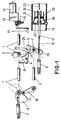
- FIG. 1 A preferred embodiment of the invention is shown in figures 1 to 7, which show the practical embodiment from a double shaft circuit-breaker drive mechanism.
- the high-voltage circuit-breaker subject of the invention comprises a mechanical drive based on a load shaft (1) and an output shaft (2).
- the load shaft (1) is duly fitted with a ratchet (3) accompanying the shaft when it moves and acting on the catch (4) lifting the same, forthwith on commencement of the connecting operation, from magnitude (r) of the self-locking cam (5) radius, in turn fixed to the output shaft (2), to a magnitude in excess of radius (R) of the same cam (5), in order to overcome the step (24) on the same cam, the catch (4) being designed to act or otherwise during the disconnection operation, on the self-locking cam (5), depending on whether or not critical short-circuit currents appear during this operation.
- the self-locking cam (5) which as aforesaid is coupled to the output shaft (2), is associated through its end opposite the catch (4) drive end to a transmission (16) relating the mobile contact (17) to the disconnection spring (6) and an interlocking and release device (26) with which the cam is integrally formed.
- the mobile contact has a piston (20) which acts in a guide cylinder (21) constituting a sort of sleeve for the said compression piston (20) to travel and to which the nozzle (19) through which the fixed contact (23) shall penetrate when the mobile contact (17) approaches the latter in the connecting operation, is coupled.
- the circuit-breaker is also provided, as aforesaid and conventionally, with a connecting spring (7) and a disconnection spring (6), a third spring (8) being provided which tends to cause the catch (4) to swing against the self-locking cam (5) and against which the ratchet (3) works coordinately.
- the connecting spring (7) acts in turn on a cam (9) whose movements are shown by the attached arrows and which have in figure 1 been represented as a solid line in the lax spring (7) state and in a broken line in the tight position thereof, the starting position in a tightening operation thereof.
- the cam (9) transmits through a transmission lever (10) the turning movement of the load shaft (1) to the output shaft (2) during the connection operation.
- the connecting spring (7) during the tightening operation thereof goes through the top dead centre on being positioned with the cam (9) and the shaft (1), thereupon to be retained in such position by action of conventional interlocking elements which allow once unlocked by external means the cam to act on the lever (10) and the latter on the shaft (2), and thus carry out the connection operation, during which the disconnection spring (6) is automatically tightened, and is in this state retained on completion of the connection operation by the device (26), figure 2.
- action on the load shaft (1) to tighten the spring (7) can be manual or through the winch (11) or automatically with the assistance of a motor reduction unit (12-13), fitted with a suitable pulling and coupling mechanism (14).
- the disconnection operation begins in which and at a predetermined time within the output shaft (2) rotation corresponding with angle ⁇ , the mobile contact (17) is separated from the fixed contact (23) by action of the disconnection spring (6), whose energy is dimensioned so that during the run of angle ⁇ it will always be greater than that corresponding with the pressures that could be originated in the compression volume by backheating and gas thermal expansion, in the event of high short-circuit current disconnection, and which are due to the dimensions of the interrupter (15) limited at that area to achieve a minimum value of such energy, so that the operating end (25) of the catch (4) safely attains at least the first retention step of the multiple stepping (24) of the self-locking cam (5) in its operative angle ⁇ , which angle determines optimal interruption and insulation separation between contacts (17) and (23).
- the catch (4) can in turn naturally be comprised by an "n" number of catches, of different length, in order that given an identical number "e” of retention steps in the self-locking cam (5), a better position e/n precision of the mobile contact can be attained.
- the number of self-locking cam steps (5) can vary, as appropriate, from one to the number required.
- the purport is that the mechanical assembly comprising elements (3), (4), (5) and (8) can be applied once or several times, to obtain the degree of robustness required in blocking the mobile contacts just when there is a tendency to invert the movement during the disconnection operation.
- the first three figures have a circuit-breaker interlocking and release device marked (26) in charge of fixing the self-locking cam (5) position when the circuit-breaker is connected, and retaining at the same time the disconnection spring (6) that was tightened by action of the cam (9) and the lever (10) during the connection operation.
- the guide cylinder (21) is provided with a frustum-shaped projection at its chamber mounting area, so that angle a can vary from 0° to 90°.
- the distance "D" of such guide cylinder can also be equal to or greater than the overall run of the piston (20) coupled to the mobile contact (17), figure 2a, or optionally greater than the maximum interruption load, corresponding to the last retention stepping provided in the direction of disconnection by combining elements (4) and (5), but less than the overall run of the mobile contact, so that in the event of the distance "D" being less than the overall run of such contact, evacuation of the gases remaining from the arc interruption will take place instantaneously when in the later displacement, after arc interruption, an exhaust area between the piston (20) and the cone-shaped wall of the guide cylinder (21), figure 2b, is produced.
- the guide cylinder (21) that can be made of a conductor or insulating material, protects the insulating chamber (15) walls and throughout the disconnection run, from metallisations, thermal shocks and so forth.
- the baffle plate (18) as shown in figures 5 and 6 can also be otherwise mounted fixed in chamber (15).
- the baffle plate, as shown in figure 6, can be hollow, in order for the gases crossing the same and operating throughout the volume in the precinct delimited by the mobile contact (17) piston (20) and the guide cylinder (21) and the base to which the latter is coupled which forms part of the interrupter (15) to achieve an optimal mixture and flow of the fresh precompressed gas with the gases from the arc area.
- the high-voltage circuit-breaker subject of the invention has the advantages of the puffer type and self blast type circuit-breakers, albeit eliminating the problems of either of them, affording an extremely simple structure, both as regards the drive means and the arc interruption means, allowing low-cost conventional materials to be used, and a low pressure in the insulating and blast means.
- figure 2 marked with references h and k respectively show the overall piston and maximum arc interruption runs.
- figure 4 sets forth the curves showing the disconnection movement curves under different short-circuit currents.
- the upper curve shows the circuit-breaker disconnection movement the right margin of which represents the three self-locking cam (5) operating angles.
- the energy imparted by the disconnection spring (6) is dimensioned in order to be greater than that caused by the pressures produced by compression and backheating of the gas that can be presented in the compression volume, for in this area, by dimensions, a given value cannot be exceeded, inasmuch as maximum blast peaks cannot appear therein.
- angle ⁇ is the optimal separation distance between the circuit-breaker contacts to cause arc interruption.
- the lower curves in this figure 4 refer to the position or run of the contacts, and the first one shows the pressure increases attained in the compression volume under different short-circuit currents, showing that with maximum strengths the pressure increase is very high, and drops as the value of the short-circuit strength diminishes.
- sine curves show the position of short-circuit currents corresponding to the above pressure curves, that can be presented through the circuit-breaker until their interruption.
- TTR characteristic curve
- the operation shaft (201) is duly provided with two blocks of elements one of which (203) is designed to load the energy accumulator (202) and the other (204) is fitted with the circuit-breaker interlocking and release elements (204.1, 204.2, 215) in turn associating the latter with a self-locking mechanism (204.3, 216) that is activated, as appropriate, during the disconnection operation, whether or not critical short-circuit currents arise during this operation.
- the said blocks of elements, load (203) and interlocking, release and self-locking (204), are related to each other through a suitable coupling (205) that uncouples the same during the energy accumulator load operation (202) and in turn couples the same through the radial coupling (201.1) to the operating shaft (201) during the circuit-breaker operation or operating cycles.
- the operating shaft (201) is provided with a lever (optionally with other elements) (206) coupled to it, relating the latter through a transmission (207) or optionally a more complex transmission system, to the mobile contacts (208) in the interrupters.
- the said mobile contact has a piston (221) acting in a guide cylinder (220) constituting a sort of sleeve for the said compression piston (221) to slide, to which the nozzle (222) is in turn coupled, through which the fixed contact (217) will enter when the mobile contact (208) moves towards the latter in the connection operation.
- the load block (203) essentially comprises a cam (203.1) coupled to a cylindrical projection which turns about an operating shaft (201) and on which a flexible transmission (209) is rolled, acting during loading and unloading of the energy accumulator (202), of a one-way radial coupling system (210) associated to a ring gear (211), the latter two designed to load the energy accumulator by conventional external means, automatically by means of a motor reduction unit or manually by means of a winch and of a likewise one-way axial semi-coupling (205) working against the direction of the former (210), relating this block to the interlocking, release and self-locking block of the circuit-breaker (204) as aforesaid.
- the interlocking, release and self-locking block (204) is fixed to the operation shaft (201) in the direction of rotation by means of a suitable coupling (201.1), can travel freely in the axial direction and has a one-way axial semi-coupling (205) designed to couple the same with the load block (203) during circuit-breaker operation, to such end, and in the direction of the load block, it is permanently acted upon by a resilient element (214).
- This block also has a double step retention cam (204.1 and 204.2) coupled thereto which is in turn fitted with an interlocking and release mechanism (215) to drive circuit-breaker operation by external conventional means.
- the body of this block is on its outer diameter and on the turning arc corresponding to the disconnection operation subdivided into two angles ⁇ and ⁇ with a step at the start of both angles and has a stepping or multiple gearing on the arc corresponding to angle ⁇ (204.3) associated in turn to a catch or catches (216) acted on by buffer springs, such elements forming in association a self-locking mechanism automatically preventing all backward movement against the rotation of the shaft in the disconnection operation and hence all tendency to invert the movement of the mobile contacts of the chambers during the maximum interruption run thereof.
- the disconnection operation begins in which and at a predetermined time within the operating shaft (201) rotation corresponding with angle ⁇ , the mobile contact (208) is separated from the fixed contact (217) by action of the force supplied by the energy accumulator (202), whose energy for this operation is dimensioned so that during the run of angle ⁇ , in addition to that required to attain the required disconnection speed, it will always be greater than that corresponding with the pressures that could be originated in the compression volume by backheating and gas thermal expansion, in the event of high short-circuit current disconnection, and which are due to the dimensions of the interrupter (218) limited at that area to achieve a minimum value of such energy, so that the operating end of the self-locking ratchet (216) safely attains at least the first retention step of the multiple stepping (204.3) of the block (204) arranged within angle ⁇ , which first step determines a run of the mobile contact (208) equal to or greater than the distance "C
- the above energy accumulator (202) energy dimensioning corresponding to the disconnection operation is sufficient to make this operation safely and fully (freely sliding the operating end of the self-locking catch (216) on the multiple stepping (204.3) of the block (204)), the subject circuit-breaker acting in this range of currents under the principle of puffer type simple compression piston with the advantages inherent therein and above-described.
- the catch or catches will continue to move on the successive steps in order that in the event of there being a tendency for the mobile contact (208) to move back due to later pressure increases in the compression volume of the interrupter (218), the said mobile contact will be locked right in the position at which the same tends to begin such back movement, preventing the same from taking place to a greater or lesser extent, by the action of elements (204), (204.3) and (216), whereupon the circuit-breaker will be in a position to extinguish the arc by self blast by thermal expansion, viz.
- the catch (216) can in turn naturally be comprised by an "n" number of catches, of different length, in order that given an identical number "e” of retention steps in the multiple stepping (204.3) of the block (204), a better position e/n precision of the mobile contact can be attained.
- the number of steps in the arc ⁇ corresponding with the stepping (204.3) can vary, as appropriate, from one to whatever number is required, and may be arranged on the said variable arc.
- the above-mentioned self-locking mechanism viz. the multiple stepping (204.3) and the self-locking catches (216) can be located elsewhere in the system transmitting the circuit-breaker operating shaft (201) movement to the mobile contacts (208) of the interrupters (218), even on the actual mobile contacts, as shown in figure 10c, with the relevant linkage (224) to be operated from the operating shaft (201).
- the arrangement of the said elements can, depending on their position, be internal or external to the interrupters (218), or a combination of both arrangements.
- the guide cylinder (220) is provided with a frustum-shaped projection at its chamber mounting area, so that angle ⁇ can vary from 0° to 90°.
- the distance "D" of such guide cylinder can also be equal to or greater than the overall run of the piston (221) coupled to the mobile contact (208), figure 10a, or optionally greater than the maximum interruption load, corresponding to the last retention stepping provided in the direction of disconnection on block (204) area (204.3), but less than the overall run of the mobile contact, so that in the event of the distance "D" being less than the overall run of such contact, evacuation of the gases remaining from the arc interruption will take place instantaneously when in the later displacement, after arc interruption, an exhaust area between the piston (221) and the cone-shaped wall of the guide cylinder (220), figure 10b, is produced.
- the guide cylinder (220) that can be made of a conductor or insulating material, protects the insulating chamber (218) walls and throughout the disconnection run from metallisations, thermal shocks and so forth.
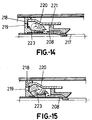
- the baffle plate (223) as shown in figures 14 and 15 can also be otherwise mounted fixed in chamber (218).
- the baffle plate, as shown in figure 15, can be hollow, in order for the gases crossing the same and operating throughout the volume in the precinct delimited by the mobile contact (208) piston (221) and the guide cylinder (220) and the base to which the latter is coupled which forms part of the interrupter (218) to achieve an optimal mixture and flow of the fresh precompressed gas with the gases from the arc area.
- the high-voltage circuit-breaker subject of the invention has the advantages of the puffer type and self blast type circuit-breakers, albeit eliminating the problems of either of them, affording an extremely simple structure, both as regards the drive means and the arc interruption means, allowing low-cost conventional materials to be used, and a low pressure in the insulating and blast means.
- figure 10b marked with references h and k respectively show the overall piston and maximum arc interruption runs.
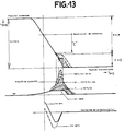
- figure 13 sets forth the curves showing the disconnection movement curves under different short-circuit currents.
- the upper curve shows the circuit-breaker disconnection movement the right margin of which represents the two circuit-breaker interlocking and release block (204) operating angles.
- ⁇ area of the circuit-breaker interlocking and release block (204) wherein the contacts are separated at a point so represented on the said curve.
- the energy imparted by the energy accumulator (202) is dimensioned in order to be greater than that caused by the pressures produced by compression and backheating of the gas that can be presented in the compression volume, for in this area, by dimensions, a given value cannot be exceeded, inasmuch as maximum blast peaks cannot appear therein.
- the distance "C" from the separation of contacts is the least optimal separation distance between the circuit-breaker contacts for arc interruption.
- the lower curves in this figure 13 refer to the position or run of the contacts and the first shows the pressure increases attained in the compression volume under different short-circuit currents, showing that with maximum strengths the pressure increase is very high, and drops as the value of the short-circuit strength diminishes.
- sine curves show the position of short-circuit currents corresponding to the above pressure curves, that can be presented through the circuit-breaker until their interruption.
- TTR characteristic curve
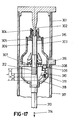
- FIG. 17 A third preferred practical embodiment is shown in figures 17 to 21; in light of these figures, and more specifically figure 17, it is clear that the interrupters (301) of the high-voltage circuit-breaker subject of the invention and one of which is shown diagrammatically in this figure in the "connected" position, basically comprises a gas-tight insulating vessel submitted to a given filling pressure with the insulating gas used (for instance SF6). One of its ends is provided with the fixed contact coupled to a connecting terminal. Opposite the above is arranged the mobile contact assembly.
- This mobile contact is essentially comprised by a guide tube fitted with contact fingers, a nozzle and a compression piston, all coupled to each other.
- the mobile contact assembly is in turn housed in a guide cylinder coupled to a base plate from which a second connecting terminal projects, and is electrically connected to the said base plate by means of sliding contacts that are not shown.
- the elements: mobile contact, guide cylinder and base plate make up a thermal expansion and compression volume.
- On the base plate and associated therewith is a membrane designed to seal off the thermal expansion and compression volume during the disconnection operation and to allow the flow of insulating gas to fill the said volume during the connection operation.
- the chambers are moreover completed with earth insulators, likewise gas-tight, submitted to the same insulating gas filling pressure of the chambers, being directly connected thereto. Inside the earth insulators are disposed transmission bars and the levers relating the mobile contacts and the circuit-breaker drive mechanism not shown in the figure.
- the interrupter is provided with an automatic self-locking mechanism working in the disconnection operation allowing, as appropriate, blast and arc interruption by the combined compression/self blast by thermal expansion of the insulating gas, subject of the present invention.
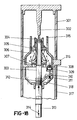
- the self-locking mechanism fitted directly in the interrupter (301) essentially comprises one or several assemblies consisting of the following elements:
- a pneumatically driven piston (309) located in the base plate (316) and whose operating surface is directly connected through the holes (308) with the compression volume (306).
- This piston in turn acts through a rod on one of the ends of a catch (310) swinging about its shaft, which is in turn fixed in a frame-shaped extension of the base plate (316).
- a buffer spring (311) also resting on the extension of the base plate (316) acts permanently against the catch (310) and in turn against the piston (309) holding the same in the position shown in figure 17.
- the guide tube of the mobile contact (303) is provided with a gearing or multiple stepping (312) forming in conjunction with the aforesaid elements the self-locking mechanism.
- the self-locking mechanism is driven by the blast generated during the compression volume disconnection operation (306) through the holes (308) on the surface of the action piston (309) and against the buffer spring (311) so that the self-locking catch swings and rests its operating end (318) on the surface of the guide tube of the mobile contact (303), being thus ready to fulfil its self-locking function.
- This mechanism will be dimensioned so that such catch (310) will swing during run M or up to no more than 2/3 of run N.
- the disconnection operation begins and consequently compression of the gas contained in the compression volume (306).
- the mobile contact (303) is separated from the fixed contact (302) by action of the force supplied by the circuit-breaker drive mechanism (314), whose energy for this operation is dimensioned so that during the run N, in addition to that required to attain the required disconnection speed, it will always be greater than that corresponding with the pressures that could be originated in the compression volume (306) by backheating and gas thermal expansion, in the event of high short-circuit current disconnection, and which are due to the dimensions of the interrupter (301) limited at that area to achieve a minimum value of such energy, so that the operating end (318) of the self-locking catch (216) safely attains at least the first retention step of the multiple stepping (312) located at area 0.
- This first retention step determines a distance "C" (figure 17 and figure 20), which is the optimal minimum interruption and insulation
- the above circuit-breaker drive (314) energy dimensioning corresponding to the disconnection operation is sufficient to make this operation safely and fully (freely sliding the operating end (318) of the self-locking catch (310) on the multiple stepping (312) of the mobile contact (303)), the subject circuit-breaker acting in this range of currents under the principle of puffer type simple compression piston with the advantages inherent therein and above-described.
- the catch (310) can in turn naturally be comprised by an "n" number of catches, of different length, in order that given an identical number "e” of retention steps in the multiple stepping (312) of the mobile contact (303), a better position e/n precision of the mobile contact can be attained.
- the number of steps in the area O corresponding with the stepping (312) can vary, as appropriate, from one to whatever number is required, and may be arranged on the said variable area.
- the above-mentioned self-locking mechanism (309, 310, 311) can also be used once or as many times as may be required on the same interrupter (301), to obtain the required rigidity for high short-circuit powers. An even greater position precision than as above would be possible on locating (for instance) the catch hinge shafts (310) at different heights.
- connection operation of the automatic self-locking mechanism (309, 310, 311 and 312) remains idle, allowing the mobile contacts (303) to move freely in this operation, for there is no pressure increase during the same in the thermal expansion and compression volume (306) of the interrupters (301).
- the high-voltage circuit-breaker subject of the invention has the advantages of the puffer type and self blast type circuit-breakers, albeit eliminating the problems of either of them, affording an extremely simple structure, both as regards the drive means and the arc interruption means, allowing low-cost conventional materials to be used, and a low pressure in the insulating and blast means.
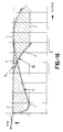
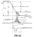
- the upper part of figure 20 shows the range of possible curves for the disconnection movement under the various short-circuit currents.
- the distance “C” determines the least optimal interruption and insulation distance between the fixed (302) and mobile (303) contacts.
- Curve I delimits a minimum overall run of the mobile contacts (303) in which case self-locking would take place at the end thereof in an only retention step.
- Curve II shows an overall run of the mobile contacts (303) greater than the above, in which case the number of retention steps in the multiple stepping (312) can vary from 2 to whatever number is necessary.
- the energy imparted by the circuit-breaker drive mechanism (314) is dimensioned in order to be greater than that caused by the pressures produced by compression and backheating of the gas that can be presented in the thermal expansion and compression volume (306), for during the same, by dimensions of the interrupter (301) and suitable operating speed of the mobile contact (303), a given value cannot be exceeded, inasmuch as maximum blast peaks cannot appear therein.
- the automatic self-locking mechanism (309, 310, 311, 312) is pneumatically activated as aforesaid, so that on moving from area O where the multiple stepping (312) can be found on the mobile contact (303), in the event of a critical average-high short-circuit current, at which the pressure generated, as aforesaid, in the thermal expansion and compression volume (306) might exceed the instantaneous value of the energy imparted by the circuit-breaker drive mechanism (314) and hence induce the movement to be inverted, the above-described self-locking mechanism (309, 310, 311, 312) would start to work.
- the central curves in this figure 20 refer to the position or run of the contacts and show the pressure increases attained in the compression volume under different short-circuit currents, showing that with maximum strengths the pressure increase is very high, and drops as the value of the short-circuit strength diminishes.
- the sine curves show the position of short-circuit currents corresponding to the above pressure curves, that can be presented through the circuit-breaker until their interruption.
- TTR characteristic curve
Landscapes
- Circuit Breakers (AREA)
Abstract
Description
- The present invention relates to a gas high-voltage circuit-breaker, with interrupters similar to the kind having a compression piston, acting however under a mixed arc interruption principle, either by simple compression or by self blast by thermal expansion, and in limiting cases within the action ranges of both principles, by combining the two. In the range of low-average short-circuit currents the circuit-breaker subject of the invention acts under the principle of simple compression piston. In the range of average-high short-circuit currents it acts under the principle of self blast by thermal expansion, self-locking during the disconnection operation by means of a suitable mechanism the mobile contacts of its interrupters to form a fixed volume, transitory therein until interruption of the arc, suited for the operation of this principle, and which structural characteristics have been designed in order to achieve therefor an optimal functional performance, specifically in the disconnection operation and against the short-circuit currents inherent therein, all with a remarkable low energy level in the driving mechanism used to operate the same and a high interruption power in high short-circuit currents.
- It is well-known that in the field of high-voltage circuit-breakers, using gas as insulating arc interruption means, three distinct solutions have to date been used, namely simple compression piston, commonly designated "puffer", self blast by thermal expansion, commonly designated "self blast", and self blast by thermal expansion with auxiliary compression piston.
- The puffer system, most widely used nowadays in average and high-voltage, albeit significantly advantageous, being in particular simple as to operating principle and in construction, low-cost conventional materials with a well-known performance as regards aging, highly effective and regular in extinguishing all the range of short-circuit currents, with very short arc times, largely the same at all short-circuit levels, little erosion at the nozzles and little wear at the arcing contacts, capable of self-regulating the vacuum generated pressure, in cases of nozzle wear under extreme accumulated arcing stress, by automatically increasing the disconnection speed and low pressures of the insulating gas used, for instance sulphur hexafluoride, however has its most severe problem in that the disconnection energy required increases directly in proportion to the increase of the short-circuit currents. In fact, very powerful robust mechanical, pneumatic or hydraulic drives are required for very strong short-circuits, for in this principle the thermal expansion and backheating pressure of the gas in the compression volume acts directly on the drive.
- The self blast system with fixed expansion volume has to date only been used in average voltage, and though its performance is very good in very small currents, it requires a low energy level, has a high interruption power in maximum short-circuit currents and, using a coil for arc rotation, performance is improved at average-low levels of the short-circuit intensity and wear wear of contacts and nozzles is reduced, it none the less has a wide range of disadvantages that are mainly as follows:
- Delicate principle requiring a high constructive precision.
- Expensive and sophisticated materials to reduce erosion at the nozzles and communication slots to the fixed heating and expansion volume, for in this principle speed and interruption in average-low short-circuit currents is very sensitive to the wear of these elements inasmuch as the thermal contribution of the arc at such levels is very low.
- Little accumulated experience on the performance in time of the materials used.
- Variable arc times in accordance with the short-circuit level, generally rather longer than with a compression piston.
- High filling pressures of the interrupters with the blast and insulation means, which means that they must be robustly dimensioned.
- Danger of the walls of the fixed heating and expansion vessel being metallised during disconnection of the average-high level of the short-circuit currents, given that the expansion volume must be rather small, and hence the level of insulation under accumulated arc stresses can be reduced.
- Increased cost of the principle in the event of an arc turning coil being used and accumulated problems due to the difficulties that switching the short-circuit current to the coil entails.
- Finally and with regard to self blast by thermal expansion with mobile volume and auxiliary compression piston: this system provides an improved performance at the low-average short-circuit levels as compared with the principle of simple self blast, by using an auxiliary compression piston to blast this range of currents and eliminate the possible dielectric problems by metallisation of the insulating walls, due to projected metallic vapours or deposits, but however also poses a wide number of problems, that in turn actually comprise the following:
- The mobile mass is largely increased.
- There are two separate volumes, a thermal expansion and a compression volume.
- Blast gates are introduced gauged precisely so that at high short-circuit levels with rapid pressure increases in the thermal expansion volume, the pressure originating in the compression volume is evacuated through the same towards the exhaust.
- For the above reason, increase of the required drive energy.
- An increased cost due to the piston and auxiliary compression volume, plus the blast gates at the three chambers.
- Arc times in excess of those of the puffer system.
- The high-voltage circuit-breaker subject of the invention has all the advantages of a conventional puffer type circuit-breaker in the range of low-average short-circuit currents, working in this field under such principle whence the problems of the aforesaid other principles are eliminated in this range of currents.
- From the range of average-high short-circuit currents in which a puffer begins to experience difficulties (increase of disconnection energy required by generation, backheating and thermal expansion of the gas, high pressures in the compression volume) it automatically selflocks the mobile contacts of the interrupters precluding their back motion and contemporaneously determining therein during the self-locking period a suitable fixed volume, so that the circuit-breaker that had until then worked as a conventional puffer will automatically start to work by self blast by thermal expansion of the gas contained in the same volumes, viz. as a self blast until arc interruption is over, with the characteristic advantages of this principle in this range of short-circuit currents.
- Right after arc interruption and hence evacuation of the remaining expansion volume pressure the mobile contacts are automatically unlocked since the cause thereof shall be no longer, and the total disconnection run of the circuit-breaker will be over.
- As described above, the subject circuit-breaker combines the advantages of both operating principles, namely puffer and self blast, without having any of their disadvantages, moreover affording the advantage that in the self blast operating area precompression due to the above puffer type actuation allows the gas filling pressure in the circuit-breaker chambers to be significantly reduced with regard to the filling pressures required in circuit-breakers working only under the self blast principle.
- In accordance with the characteristics of the invention the mobile circuit-breaker contacts have in addition to the classic connecting and disconnection springs and other auxiliary elements been provided to have a self-locking device, so that once the contact has started on the disconnection movement it can by no means move back at any point of the operation in which this tends to take place.
- More specifically, the circuit-breaker is structured as a puffer type circuit-breaker, viz. provided with an interrupter in which a membrane is provided crossed by the mobile contact and which determines a chamber with the configuration of a guide cylinder in which the compression piston plays, likewise crossed by the mobile contact and framed by a nozzle which moves jointly with the piston and the mobile contact to clamp the fixed contact, but with the exception that the said mobile contacts, and as aforesaid, are associated to a self-locking device which determines, also as aforesaid, that when the force corresponding to the pressure generated in the chambers by backheating (thermal expansion) is greater than the instantaneous force imparted by the disconnection spring, the mobile contact is automatically locked by the said self-locking device, the mobile contact being held still and the circuit-breaker now acting as a classical self blast type circuit-breaker, which position is sustained until the arc is interrupted, the residual sweep pressure being immediately evacuated when the mobile contact completes its disconnection run by means of the energy left in the disconnection spring.
- More specifically and in order to achieve the above, the circuit-breaker subject hereof is structured from a mechanical drive mechanism based on a load shaft and an output shaft, connected to each other by a cam and a transmission lever, wherein the load shaft is driven by action of any suitable drive element, for instance a motor reduction unit or a winch, acting on the said shaft through a suitable drive and coupling mechanism, to tighten the connecting spring.
- The shaft load is in addition to the said cam on which the connecting spring acts also integrally provided with a ratchet which coordinates the position of one or several catches fitted with buffer springs so that during the connection operation which entails the automatic tightening of the disconnection spring the said buffer springs allow the output shaft to rotate freely and hence the mobile contacts of the interrupters to move in such direction, releasing to such end the multiple steps of the self-locking cam fixed to the output shaft and associated to a transmission which relates the mobile contacts to the disconnection spring. During a disconnection operation in which the disconnection spring is hence in operation, the above- described ratchet will irrespective of the position it is in (taught or lax connecting spring) allow the said catch or catches to move freely on the self-locking cam, progressively sliding on the operating profile thereof as the mobile contact moves in the disconnection movement direction, so that in the event of disconnection of a high enough short-circuit current capable, due to the pressure generated thereby in the compression volume, of causing the said movement to tend to be inverted, the mobile contact will be automatically locked by the self-locking cam step in which the operating end of the catch or one of the catches is at the time.
- To supplement the above structure the fixed and mobile contacts are housed within an interrupter, which could in principle be said to be similar to the puffer type, which has a membrane crossed by the mobile contact, a guide cylinder associated to the said membrane, a piston which slides within the said guide cylinder and a nozzle associated in turn to the said piston.
- In accordance with this structure and as above mentioned, with average-high short-circuit currents with which a pressure could be generated in a disconnection operation, by backheating and thermal expansion of the gas, capable of overcoming the disconnection spring tension, the mobile contact would be automatically locked by the self-locking mechanism and the circuit-breaker that would have thitherto worked as a puffer would now work as a self blast, i.e. by self blast by thermal expansion until the arc was extinguished, on determining by action of the said mechanism a predetermined volume in the compression chamber, or in other words with the most ideal solution for these average-high short-circuit currents.
- In accordance with a simpler embodiment of the invention the high-voltage circuit-breaker is basically structured from a mechanical drive mechanism having an only circuit-breaker operating shaft and an energy accumulator, either mechanical comprising a spring or spring package, or a duly adapted spiral spring, or any other kind of energy accumulator (hydraulic, hydro-pneumatic and so forth) capable of storing the energy required for the various circuit-breaker operating cycles.
- The operating shaft is provided with two blocks of elements, the first being designed to load the energy accumulator and the latter comprising the circuit-breaker interlocking and release elements, the latter being combined with the self-locking mechanism, working as appropriate, in the disconnection operation. These two blocks of elements are related to each other by means of a suitable coupling which uncouples both while the energy accumulator is being loaded and joins the same during circuit-breaker operation or operating cycles. The shaft is further integrally provided with a lever (optionally other elements such as cams) relating the same through a transmission or other transmission means to the mobile contacts in the chamber.
- The load block essentially comprises a cam turning on the operating shaft and on which a flexible transmission is coiled acting while loading and unloading the energy accumulator or a suitable system in the event of any other kind of energy accumulator being applied, with a one-way radial coupling system, for instance a freewheel, otherwise called free gear coupling, associated to a ring gear designed to load the energy accumulator by external means, automatically by means of a motor reduction unit or manually by means of a winch, and a likewise one-way axial semi-coupling working in a direction contrary to the above, relating this block to the interlocking, release and self-locking block, as aforesaid.
- The interlocking, release and self-locking block is fixed to the operating shaft in the direction of rotation by means of a suitable coupling (pin, knurling and so forth), can move freely axially and has a one-way axial semi-coupling designed for coupling with the load block during circuit-breaker operation, to which end it is, in the direction of the load block, permanently acted upon by a resilient element. This block is further provided with a retention cam having two steps integral therewith associated to an interlocking and release mechanism to drive by external and conventional means the circuit-breaker operation. The body of this block is, on its outer diameter and on the turning arc corresponding to the disconnection operation, provided with a stepping or multiple gearing associated to a catch or catches acted upon by buffer springs or else by the force of gravity, forming in their association a self-locking mechanism that automatically prevents all and any back movement against the direction of rotation of the shaft in the disconnection operation and hence all tendency to invert the movement of the mobile contacts in the chambers.
- The above axial semi-couplings, which associate the load block and the retention block and the aforesaid resilient element, can be replaced by another element (for instance another freewheel) or duly arranged elements fulfilling such function, in which event the circuit-breaker operating shaft could be directly coupled with the interlocking, release and self-locking block.
- Thus and in the event of a critical short-circuit current high enough and capable due to the pressure thereby generated in the compression volume of causing a tendency to invert the said movement, the mobile contact would be automatically locked by the step in the self-locking mechanism positioned at the time at the operating end of the one catch or one of the catches.
- To supplement the above structure the fixed and mobile contact are housed within an interrupter that could be in principle be said to resemble the puffer type, having a membrane crossed by the mobile contact, a guide cylinder associated to the said membrane, a compression piston sliding within the said guide cylinder and a nozzle in turn associated to the said piston.
- In accordance with this structure and as aforesaid, in the event of average-high short-circuit currents, with which a pressure could be generated in a disconnection operation, by backheating and thermal expansion of the gas, capable of overcoming the instantaneous voltage supplied by the energy accumulator, the mobile contacts would be automatically checked by the self-locking mechanism and the circuit-breaker that would have thitherto worked as a puffer would now work as a self blast, viz. self blast by thermal expansion until arc interruption, when the said mechanism action determines a predetermined volume in the compression chamber, i.e. with the most ideal solution for these average-high short-circuit currents.
- To supplement the energy accumulator in accordance with the objective characteristics that the circuit-breaker must meet, the use of other springs is also provided to supplement the circuit-breaker's function, either in the disconnection operation as acceleration spring, or to obtain a suitable energy balance between those required for connection and disconnection, such being fitted for instance within the actual circuit-breaker poles or chambers, or supporting the energy accumulator for the connecting operation.
- Finally and in accordance with another practical embodiment of the invention, the self-locking means for the mobile contact comprises a mechanical-pneumatic mechanism that, in addition to being directly fitted in the interrupters thereof, is operated automatically from the pressure increases in the compression volumes and thermal expansion thereof in the disconnection operation and allows, as appropriate, the blast and interruption of the arc by the mixed principle of compression/self blast by thermal expansion of the insulating gas.
- The self-locking mechanism fitted directly in the interrupter essentially comprises one or several assemblies formed by a pneumatic piston directly operated by the pressure increase in the compression volume through a gas opening passage, a catch swinging about a shaft, a buffer spring permanently acting against the said pneumatic piston and a stepping or multiple gearing conveniently arranged on the guide tube of the mobile contact, and on which as appropriate the said catches or assemblies act. With the exception of the multiple stepping, the other elements can be located in the base plate of the interrupter.
- The subject self-locking mechanism on being acted by the pressure increase in the compression volume (pneumatic pressure greater than the strength of the buffer spring) prevents all tendency to invert the movement of the mobile contacts of the chambers during the disconnection operation when the catch or one of the catches is automatically interlocked in the relevant step of the multiple stepping of the guide tube, at the very moment in which such tendency begins, thereby for the circuit-breaker operating drive power to be successfully reduced practically to that required to accelerate the mobile masses and attain the required operating speeds.
- In the event of this tendency not coming about (average-low short-circuit currents) the operating end of the catch or catches will freely slide on the multiple stepping profile during the disconnection operation.
- The blast value in the compression volume for dimensioning and operating the self-locking mechanism may be chosen from among those produced by the movement in a vacuum of the mobile contacts in the disconnection operation and as considered appropriate, generated from a given level of the short-circuit current.
- During the connection operation the said mechanism remains idle allowing the mobile contacts to move freely in this operation, for during the same there are no pressure increases in the compression volume of the interrupters and hence the self-locking mechanism is not activated.
- In accordance with this structure and as aforesaid in the event of critical average-high short-circuit currents with which pressures could be generated in a disconnection operation, in the compression volumes of the interrupters, by backheating and thermal expansion of the insulation gas used, capable of overcoming the instantaneous voltage or force supplied by the accumulator drive, the mobile contacts would be automatically checked by the self-locking mechanism and the circuit-breaker that would have thitherto worked as a puffer would now work as a self blast, viz. self blast by thermal expansion, in other words with the most ideal solution for these cases, when the said mechanism action defines a predetermined volume in the compression chamber, transitory therein until arc interruption.
- In order to provide a fuller description and contribute to the complete understanding of the characteristics of this invention, a set of drawings is attached to the specification which, while purely illustrative and not fully comprehensive, shows the following:
- Figure 1.- Is a diagrammatic view of a high-voltage circuit-breaker made in accordance with the object of the present invention, which appears disconnected and with the connecting (7) and disconnection (6) springs lax.
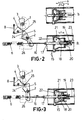
- Figure 2.- Is a partial detail of the above figure, in this case pertaining to the position with the circuit-breaker connected and with the disconnection spring (6) tight during the connecting and holding operation in the circuit-breaker disconnection interlocking and release mechanism (26).
- Figure 3.- Is finally the assembly of figure 2, in an intermediate retention position in which the circuit-breaker no longer works as a puffer and begins to do so as a self blast, by action of a critical short-circuit strength in the average-high range, with the principle subject of this invention acting to such end.
- Figure 4.- Shows the ranges of the possible curves of the disconnection movement under high short-circuit currents, and the pressure increases generated by the same in the compression volume and thermal expansion of the gas.
- Curve I: where the overall run is greater than the retention field of the self-locking mechanism.
- Curve II: where the overall run matches the first retention step in the self-locking mechanism (5).
- Curve III: where the overall run matches the last retention step in the self-locking cam (5).
- Figures 5 and 6.- Show two baffle plate options, with the baffle plate mounted in the chamber, instead of being coupled to the mobile contact.
- Figure 7.- Is a diagram showing a characteristic curve (TTR as a function of Icc) of the circuit-breaker subject of the present invention curve A, showing the advantages thereof as compared with the two classic circuit-breakers having the same energy level for their respective drives, with the puffer curve B and self blast curve C type operating principles.
- Figure 8.- Is a diagrammatic view of a high-voltage circuit-breaker provided with the said self-locking interlocking device comprising the essential foundation of the invention, to achieve the mixed principle of interruption by simple compression/self blast by thermal expansion.
- Figure 9.- Is a diagram corresponding to a characteristic curve (TTR as a function of Icc) of the circuit-breaker of the above figure curve A, showing its advantages as compared with two classic circuit-breakers, with the puffer curve B and self blast curve C type operating principles.
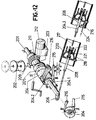
- Figure 10.- Is a diagrammatic view of a high-voltage circuit-breaker made in accordance with the embodiment in which the same is fitted with a single operating shaft, in the circuit-breaker drive mechanism, which is in the connected position and in this case with a spring energy accumulator tightened and retained in the circuit-breaker interlocking and release mechanism.
- Figure 11.- Is the assembly of figure 10, during a disconnection operation, in an intermediate self-locking position in which the action of a critical short-circuit strength of the average-high range causes the circuit-breaker to cease acting as a puffer to begin doing so as a self blast, the principle subject of the present invention acting to such end.
- Figure 12.- Is the assembly of the above figure, in this case representing the disconnection circuit-breaker position with the energy accumulator tightened and retained in the circuit-breaker interlocking and release mechanism.
- Figure 13.- Shows the ranges of the possible curves of the disconnection movement under short-circuit currents, in particular under high short-circuit currents, and the pressure increases generated thereby in the compression volume and gas thermal expansion, in accordance with a given position of the moment in which the contacts of the interrupters are separated by symmetrical or asymmetrical currents. Distance "C" defines the least optimal distance of the arc from the contacts separation. Angle β is the run of the mobile contact up to the first retention step and angle τ stands for the position area of the stepping for automatic self-locking of the mobile contacts.
- Figures 14 and 15.- Show two interrupter options in which the baffle plate is mounted in the chamber, instead of being coupled to the mobile contact.
- Figure 16.- Is a diagram showing a characteristic curve (TTR as a function of Icc) of the circuit-breaker subject of the present invention curve A, showing its advantages as compared with two classic circuit-breakers having the same energy level of their respective drives, with the puffer curve B and self blast curve C type operating principles.
- Figure 17.- Is a diagrammatic view of an interrupter in a high-voltage circuit-breaker made in accordance with the object hereof, in the position of connected circuit-breaker and with the self-locking mechanism at rest (idle).
- Figure 18.- Is the assembly of figure 17, during a disconnection operation, in an intermediate self-locking position in which the action of a critical short-circuit strength of the average-high range causes the circuit-breaker to cease acting as a puffer to begin doing so as a self blast, the principle subject of the present invention acting to such end. Which self-locking mechanism is driven by the pressure increase in the compression volume (306).
- Figure 19.- Is the assembly of the above figure, in this case pertaining to the circuit-breaker disconnection position and with the self-locking mechanism at rest.
- Figure 20.- Is the ranges of possible curves for the disconnection movement under short-circuit currents, in particular under high short-circuit currents, and the pressure increases generated thereby in the compression and gas thermal expansion volume, in accordance with a given position of the moment in which the interrupter contacts are separated by symmetrical or asymmetrical currents.
Distance "C" defines the least optimal distance of the arc between the fixed and mobile contacts from contacts separation. - Figure 21.- Is a diagram showing a characteristic curve (TTR as a function of Icc) of the circuit-breaker subject of the present invention curve A, showing its advantages as compared with two classic circuit-breakers having the same energy level of their respective drives, with the puffer curve B and self blast curve C type operating principles.
- In accordance with the general embodiment principle to which figures 8 and 9 refer, the automatic circuit-breaker is structured with a mobile contact (101) and a fixed contact (102), the first fitted for instance with a connecting spring (103) and a disconnection spring (104) or other mechanism driving the circuit-breaker, fully shown diagrammatically in figure 8, and further and now as in a puffer type conventional circuit-breaker with an interrupter (105), a membrane (106), a guide cylinder (107), a compression piston (108) and a baffle plate (109) associated to the mobile contact (101), and a nozzle (110), the circuit-breaker being essentially characterised in being fitted with an interlocking self-locking device (111), duly associated to the mobile contact (101) in order for the device (111), once the disconnection operation has begun under a high short-circuit current, through its thermal effect, an excessive pressure is generated in the compression volumes of the interrupters by backheating and thermal expansion of the gas capable of overcoming the disconnection circuit-breaker (104) tension, to cause that the mobile contact cannot move back to tend again towards the connection position with the fixed contact (102).
- In the event of this limiting state being arrived at, the interlocking self-locking device (111) automatically determines a block of the compression piston (108) whereupon a predetermined volume will be formed between the guide cylinder (107), the mobile contact (101), the chamber (105) and the membrane (106), wherefore the circuit-breaker as a whole will start to work as a self blast, of wellknown effectiveness in extinguishing large short-circuit currents.
- The efficiency of a high-voltage automatic circuit-breaker as above described can be clearly observed in figure 9, wherein the curve B stands for the characteristics of a puffer type circuit-breaker, whose efficiency drops at high short-circuit strength values as can be observed through the drop in the curve shown, this critical area being caused by the need to use large forces or power to manage to disconnect the circuit-breaker in the driving thereof; curve B stands for a self blast circuit-breaker and can be seen to have the opposite effect, i.e. the critical circuit-breaker area is presented at small short-circuit strengths, causing dielectric problems due to the insufficient thermal contribution of the arc, viz. the blast and the sweep are insufficient; and curve A stands for a circuit-breaker made in accordance with object of the invention, the range of short-circuit average-high currents standing for the area of operation of the self-locking interlocking device, and it can be observed that curve A contains the advantages of the two systems that are currently being used, there being no critical areas at high or low short-circuit strengths, as is the case of the current principles.
- Figure 9 is a diagram showing a characteristic curve (TTR as a function of Icc) of the circuit-breaker subject of the present invention curve A, showing its advantages as compared with two classic circuit-breakers with the puffer curve B and self blast curve C type operating principles, and with keys : a, optimal puffer principle area; b, self blast by puffer type precompression performance improvement; c, optimal self blast principle area; d, critical area: dielectric problems due to insufficient thermal contribution of the arc (insufficient arc blast and sweep); e, critical area: limits due to increased energy requirement in driving = f (Icc²); f, area of improvements using the subject invention; and g, area of operation of the subject self-locking mechanism.
- A preferred embodiment of the invention is shown in figures 1 to 7, which show the practical embodiment from a double shaft circuit-breaker drive mechanism.
- In light of these figures and more specifically of figure 1, it is clear that the high-voltage circuit-breaker subject of the invention and which in this figure is shown in the disconnection position and with the connecting (7) and disconnection (6) springs lax, comprises a mechanical drive based on a load shaft (1) and an output shaft (2). The load shaft (1) is duly fitted with a ratchet (3) accompanying the shaft when it moves and acting on the catch (4) lifting the same, forthwith on commencement of the connecting operation, from magnitude (r) of the self-locking cam (5) radius, in turn fixed to the output shaft (2), to a magnitude in excess of radius (R) of the same cam (5), in order to overcome the step (24) on the same cam, the catch (4) being designed to act or otherwise during the disconnection operation, on the self-locking cam (5), depending on whether or not critical short-circuit currents appear during this operation.
- The self-locking cam (5) which as aforesaid is coupled to the output shaft (2), is associated through its end opposite the catch (4) drive end to a transmission (16) relating the mobile contact (17) to the disconnection spring (6) and an interlocking and release device (26) with which the cam is integrally formed.
- The mobile contact (17), optionally provided with a baffle plate (18), coupled to the same, slides inside an interrupter (15) in which a membrane (22) is provided. The mobile contact has a piston (20) which acts in a guide cylinder (21) constituting a sort of sleeve for the said compression piston (20) to travel and to which the nozzle (19) through which the fixed contact (23) shall penetrate when the mobile contact (17) approaches the latter in the connecting operation, is coupled.
- The circuit-breaker is also provided, as aforesaid and conventionally, with a connecting spring (7) and a disconnection spring (6), a third spring (8) being provided which tends to cause the catch (4) to swing against the self-locking cam (5) and against which the ratchet (3) works coordinately. The connecting spring (7) acts in turn on a cam (9) whose movements are shown by the attached arrows and which have in figure 1 been represented as a solid line in the lax spring (7) state and in a broken line in the tight position thereof, the starting position in a tightening operation thereof. The cam (9) transmits through a transmission lever (10) the turning movement of the load shaft (1) to the output shaft (2) during the connection operation. It can be seen that the connecting spring (7) during the tightening operation thereof goes through the top dead centre on being positioned with the cam (9) and the shaft (1), thereupon to be retained in such position by action of conventional interlocking elements which allow once unlocked by external means the cam to act on the lever (10) and the latter on the shaft (2), and thus carry out the connection operation, during which the disconnection spring (6) is automatically tightened, and is in this state retained on completion of the connection operation by the device (26), figure 2.
- As is also conventional, action on the load shaft (1) to tighten the spring (7) can be manual or through the winch (11) or automatically with the assistance of a motor reduction unit (12-13), fitted with a suitable pulling and coupling mechanism (14).
- The turning movement of shaft (1) during the connecting spring tightening operation (7) carries with it rotation of the ratchet (3) to be positioned as shown by the broken line on completion of the tightening operation, on the catch or catches (4), in order that once the shaft (1) has been unlocked to carry out a connection operation, from this position and with the cam (9) acting on the lever (10) and hence with the shaft (2) starting to turn, and therefore the self-locking cam (2) rotating, the ratchet (3) will act forthwith on an angle smaller than angle δ of rotation of the self-locking cam (5) on the catch or catches (4), lifting their operating ends (25) from a distance (r) or smaller radius of the self-locking cam (5) up to a distance in excess of (R), thereby overcoming the stepped area corresponding with angle τ, in order that on completion of the connection movement the catch or catches (4) will be free with their operating end (25) resting at the end of the arc delimited by angle β on the self-locking cam (5) profile, figure 2.
- The said three angles of the self-locking cam (5) corresponding with the actuation arcs of the catch or catches (4) and whose function was described during the connection operation with the assistance of the ratchet (3), figures 1 and 2, also delimit specific operating fields during the disconnection operation. Thus, and starting from the connection position, figure 2, once the mechanism (26) has received an unlocking order, the disconnection operation begins in which and at a predetermined time within the output shaft (2) rotation corresponding with angle β, the mobile contact (17) is separated from the fixed contact (23) by action of the disconnection spring (6), whose energy is dimensioned so that during the run of angle β it will always be greater than that corresponding with the pressures that could be originated in the compression volume by backheating and gas thermal expansion, in the event of high short-circuit current disconnection, and which are due to the dimensions of the interrupter (15) limited at that area to achieve a minimum value of such energy, so that the operating end (25) of the catch (4) safely attains at least the first retention step of the multiple stepping (24) of the self-locking cam (5) in its operative angle τ, which angle determines optimal interruption and insulation separation between contacts (17) and (23).
- In the case of average-low short-circuit currents the above disconnection spring (6) energy dimensioning is sufficient to make the disconnection operation, freely sliding the operating end (25) of the catch (5) along the operating profile of the self-locking cam (5) safely and fully, the subject circuit-breaker acting in this range of currents under the principle of puffer type simple compression piston with the advantages inherent therein and above-described.
- Going back to the case of high short-circuit currents and once the operating end (25) of the catch (4) has arrived at the multiple stepping area (24) of the self-locking cam (5) the catch or catches will continue to move on the successive steps in order that in the event of there being a tendency for the mobile contact (17) to move back due to later pressure increases in the compression volume of the interrupter (15) the said mobile contact will be locked right in the position at which the same tends to begin such back movement, preventing the same from taking place to a greater or lesser extent, by the action of elements (4), (5) and (8), whereupon the circuit-breaker will be in a position to extinguish the arc by self blast by thermal expansion, viz. as if it were a self blast type circuit-breaker, inasmuch as at that time a predetermined volume will be formed between elements (15), (19), (20), (21) and (22) of the interrupter, with all the advantages regarding its high disconnection power also described above. In particular, the detail of figure 3 shows this possibility, and more specifically the mobile contact in the self-locking position.
- Upon arc interruption the pressure in the compression volume and thermal expansion drops rapidly so that the energy stored in the connecting spring (6) when the mobile contact (17) is self-locked completes the full run of the mobile contact (17) corresponding with angle δ of the operating profile of the self-locking cam (5).
- The catch (4) can in turn naturally be comprised by an "n" number of catches, of different length, in order that given an identical number "e" of retention steps in the self-locking cam (5), a better position e/n precision of the mobile contact can be attained. The number of self-locking cam steps (5) can vary, as appropriate, from one to the number required.
- In short, the purport is that the mechanical assembly comprising elements (3), (4), (5) and (8) can be applied once or several times, to obtain the degree of robustness required in blocking the mobile contacts just when there is a tendency to invert the movement during the disconnection operation.
- The first three figures have a circuit-breaker interlocking and release device marked (26) in charge of fixing the self-locking cam (5) position when the circuit-breaker is connected, and retaining at the same time the disconnection spring (6) that was tightened by action of the cam (9) and the lever (10) during the connection operation.
- When the circuit-breaker is to be disconnected, it will be sufficient to release this interlocking and release device in order for the disconnection spring to fulfil its mission commencing disconnection and rotation of the self-locking cam (5).
- The guide cylinder (21) is provided with a frustum-shaped projection at its chamber mounting area, so that angle a can vary from 0° to 90°. The distance "D" of such guide cylinder can also be equal to or greater than the overall run of the piston (20) coupled to the mobile contact (17), figure 2a, or optionally greater than the maximum interruption load, corresponding to the last retention stepping provided in the direction of disconnection by combining elements (4) and (5), but less than the overall run of the mobile contact, so that in the event of the distance "D" being less than the overall run of such contact, evacuation of the gases remaining from the arc interruption will take place instantaneously when in the later displacement, after arc interruption, an exhaust area between the piston (20) and the cone-shaped wall of the guide cylinder (21), figure 2b, is produced.
- It is to be noted that the guide cylinder (21) that can be made of a conductor or insulating material, protects the insulating chamber (15) walls and throughout the disconnection run, from metallisations, thermal shocks and so forth.
- The baffle plate (18) as shown in figures 5 and 6 can also be otherwise mounted fixed in chamber (15). On the other hand, the baffle plate, as shown in figure 6, can be hollow, in order for the gases crossing the same and operating throughout the volume in the precinct delimited by the mobile contact (17) piston (20) and the guide cylinder (21) and the base to which the latter is coupled which forms part of the interrupter (15) to achieve an optimal mixture and flow of the fresh precompressed gas with the gases from the arc area.
- It follows from the above-described structure firstly that the high-voltage circuit-breaker subject of the invention has the advantages of the puffer type and self blast type circuit-breakers, albeit eliminating the problems of either of them, affording an extremely simple structure, both as regards the drive means and the arc interruption means, allowing low-cost conventional materials to be used, and a low pressure in the insulating and blast means.
- It is therefore also possible to sharply reduce the energy required for driving purposes and hence to achieve an enhanced mechanical performance.
- The upper detail of figure 2 marked with references h and k respectively show the overall piston and maximum arc interruption runs.
- Finally, figure 4 sets forth the curves showing the disconnection movement curves under different short-circuit currents. The upper curve shows the circuit-breaker disconnection movement the right margin of which represents the three self-locking cam (5) operating angles. During this disconnection run we come up with the angle β area of cam (5) wherein the contacts are separated at a point so represented on the said curve. In this area, the energy imparted by the disconnection spring (6) is dimensioned in order to be greater than that caused by the pressures produced by compression and backheating of the gas that can be presented in the compression volume, for in this area, by dimensions, a given value cannot be exceeded, inasmuch as maximum blast peaks cannot appear therein.
- On moving to the curve area corresponding to angle τ, where the multiple cam (5) stepping can be found, in the event of there being a critical short-circuit current, at which the pressure generated, as aforesaid, in the compression volume might exceed the instantaneous value of the energy imparted by the disconnection spring (6) and hence induce the movement to be inverted, the above-described self-locking mechanism would start to work.
- The distance limited by angle τ is the optimal separation distance between the circuit-breaker contacts to cause arc interruption.
- Finally, the curve area corresponding with angle δ of the self-locking cam (5) in which the pressure in the interrupter has dropped due to arc interruption having been completed, the disconnection spring (6) still has enough energy to fully complete the overall mobile contact (17) run, figure 4 curve I.
- It is also otherwise provided that the overall run of the mobile contact (17) end when the disconnection run reaches either the end of angle β or the end of angle τ, which coincides with the first or with the last retention step of the self-locking cam (5), respectively, in other words, with the optimal interruption and insulation distances, figure 4 curve II and curve III, respectively.
- The lower curves in this figure 4 refer to the position or run of the contacts, and the first one shows the pressure increases attained in the compression volume under different short-circuit currents, showing that with maximum strengths the pressure increase is very high, and drops as the value of the short-circuit strength diminishes.
- Finally, the sine curves show the position of short-circuit currents corresponding to the above pressure curves, that can be presented through the circuit-breaker until their interruption.
- Figure 7 shows a diagram corresponding with a characteristic curve (TTR as a function of Icc) of the circuit-breaker subject of the present invention curve A, showing its advantages as compared with two classic circuit-breakers having the same energy level of their respective drives, with the puffer curve B and self blast curve C type operating principles, and with keys : a, optimal puffer principle area; b, self blast by puffer type precompression performance improvement; c, optimal self blast principle area; d, critical area: dielectric problems due to insufficient thermal contribution of the arc (insufficient arc blast and sweep); e, critical area: limits due to increased energy requirement in driving = f (Icc²); f, (ruled surface), area of improvements using the subject invention; and g, area of operation of the subject self-locking mechanism.
- With another possible embodiment, from a single shaft circuit-breaker drive mechanism, shown in figures 10 to 16. It is clear from the same, and in particular from figure 10, that the high-voltage circuit-breaker subject of the invention and that is in the connected position in this figure, with the energy accumulator (202) loaded, comprises a mechanical drive based on a single shaft (201) to operate the circuit-breaker.
- The turning movements both when loading the energy accumulator, load block (203), and to operate the circuit-breaker (disconnection, connection), operation shaft (201), are represented by the relevant arrows, "A" for the first and "B" for the second.
- The operation shaft (201) is duly provided with two blocks of elements one of which (203) is designed to load the energy accumulator (202) and the other (204) is fitted with the circuit-breaker interlocking and release elements (204.1, 204.2, 215) in turn associating the latter with a self-locking mechanism (204.3, 216) that is activated, as appropriate, during the disconnection operation, whether or not critical short-circuit currents arise during this operation.
- The said blocks of elements, load (203) and interlocking, release and self-locking (204), are related to each other through a suitable coupling (205) that uncouples the same during the energy accumulator load operation (202) and in turn couples the same through the radial coupling (201.1) to the operating shaft (201) during the circuit-breaker operation or operating cycles.
- The operating shaft (201) is provided with a lever (optionally with other elements) (206) coupled to it, relating the latter through a transmission (207) or optionally a more complex transmission system, to the mobile contacts (208) in the interrupters.
- The mobile contact (208), optionally provided with a baffle plate (223) coupled to it, slides inside an interrupter (218) in which a membrane (219) is fitted. The said mobile contact has a piston (221) acting in a guide cylinder (220) constituting a sort of sleeve for the said compression piston (221) to slide, to which the nozzle (222) is in turn coupled, through which the fixed contact (217) will enter when the mobile contact (208) moves towards the latter in the connection operation.
- The load block (203) essentially comprises a cam (203.1) coupled to a cylindrical projection which turns about an operating shaft (201) and on which a flexible transmission (209) is rolled, acting during loading and unloading of the energy accumulator (202), of a one-way radial coupling system (210) associated to a ring gear (211), the latter two designed to load the energy accumulator by conventional external means, automatically by means of a motor reduction unit or manually by means of a winch and of a likewise one-way axial semi-coupling (205) working against the direction of the former (210), relating this block to the interlocking, release and self-locking block of the circuit-breaker (204) as aforesaid.
- The interlocking, release and self-locking block (204), is fixed to the operation shaft (201) in the direction of rotation by means of a suitable coupling (201.1), can travel freely in the axial direction and has a one-way axial semi-coupling (205) designed to couple the same with the load block (203) during circuit-breaker operation, to such end, and in the direction of the load block, it is permanently acted upon by a resilient element (214). This block also has a double step retention cam (204.1 and 204.2) coupled thereto which is in turn fitted with an interlocking and release mechanism (215) to drive circuit-breaker operation by external conventional means. The body of this block is on its outer diameter and on the turning arc corresponding to the disconnection operation subdivided into two angles β and τ with a step at the start of both angles and has a stepping or multiple gearing on the arc corresponding to angle τ (204.3) associated in turn to a catch or catches (216) acted on by buffer springs, such elements forming in association a self-locking mechanism automatically preventing all backward movement against the rotation of the shaft in the disconnection operation and hence all tendency to invert the movement of the mobile contacts of the chambers during the maximum interruption run thereof.
- The above-mentioned angles β and τ on the interlocking, release and self-locking block (204) corresponding to the slide and operating arcs of the self-locking catch or catches (216), delimit specific operating fields during the circuit-breaker disconnection operation. Thus, and starting from the connection position, figure 10, once the mechanism (215) has received a release order, the disconnection operation begins in which and at a predetermined time within the operating shaft (201) rotation corresponding with angle β, the mobile contact (208) is separated from the fixed contact (217) by action of the force supplied by the energy accumulator (202), whose energy for this operation is dimensioned so that during the run of angle β, in addition to that required to attain the required disconnection speed, it will always be greater than that corresponding with the pressures that could be originated in the compression volume by backheating and gas thermal expansion, in the event of high short-circuit current disconnection, and which are due to the dimensions of the interrupter (218) limited at that area to achieve a minimum value of such energy, so that the operating end of the self-locking ratchet (216) safely attains at least the first retention step of the multiple stepping (204.3) of the block (204) arranged within angle τ, which first step determines a run of the mobile contact (208) equal to or greater than the distance "C", figure 13, which in turn determines optimal minimum interruption separation between contacts (208) and (217).
- In the case of average-low short-circuit currents, the above energy accumulator (202) energy dimensioning corresponding to the disconnection operation is sufficient to make this operation safely and fully (freely sliding the operating end of the self-locking catch (216) on the multiple stepping (204.3) of the block (204)), the subject circuit-breaker acting in this range of currents under the principle of puffer type simple compression piston with the advantages inherent therein and above-described.
- Going back to the case of high short-circuit currents and once the operating end of the self-locking catch (216) has arrived at the multiple stepping area (204.3) of the block (204), the catch or catches will continue to move on the successive steps in order that in the event of there being a tendency for the mobile contact (208) to move back due to later pressure increases in the compression volume of the interrupter (218), the said mobile contact will be locked right in the position at which the same tends to begin such back movement, preventing the same from taking place to a greater or lesser extent, by the action of elements (204), (204.3) and (216), whereupon the circuit-breaker will be in a position to extinguish the arc by self blast by thermal expansion, viz. as if it were a self blast type circuit-breaker, inasmuch as at that time a predetermined volume will be formed between elements (218), (208), (219), (220), (221) and (222) of the interrupter, with all the advantages regarding its high disconnection power also described above. In particular, the detail of figure 11 shows this possibility, and more specifically the mobile contact in the self-locking position.
- Upon arc interruption the pressure in the compression volume and thermal expansion drops rapidly so that the energy stored in the energy accumulator (202) when the mobile contact (208) is self-locked completes its full disconnection run, until the cam (204.1) is interlocked in the interlocking and release mechanism (215), the circuit-breaker hence remaining in the disconnected position, ready for a subsequent connection operation.
- The catch (216) can in turn naturally be comprised by an "n" number of catches, of different length, in order that given an identical number "e" of retention steps in the multiple stepping (204.3) of the block (204), a better position e/n precision of the mobile contact can be attained. The number of steps in the arc τ corresponding with the stepping (204.3) can vary, as appropriate, from one to whatever number is required, and may be arranged on the said variable arc.
- The above-mentioned self-locking mechanism, viz. the multiple stepping (204.3) and the self-locking catches (216) can be located elsewhere in the system transmitting the circuit-breaker operating shaft (201) movement to the mobile contacts (208) of the interrupters (218), even on the actual mobile contacts, as shown in figure 10c, with the relevant linkage (224) to be operated from the operating shaft (201). Furthermore, the arrangement of the said elements can, depending on their position, be internal or external to the interrupters (218), or a combination of both arrangements.
- When the circuit-breaker is to be connected, figure 12, it will be sufficient to act on the interlocking and release mechanism (215), shown in the diagram, so as to release the connecting cam (204.1), for the energy accumulator to supply the necessary energy for this operation through the operating shaft (201) until completion of the turning corresponding with this operation, the mechanism (215) being again automatically interlocked in the cam (204.2) at the end thereof, the circuit-breaker therefore remaining connected and ready for a later disconnection operation.
- The guide cylinder (220) is provided with a frustum-shaped projection at its chamber mounting area, so that angle α can vary from 0° to 90°. The distance "D" of such guide cylinder can also be equal to or greater than the overall run of the piston (221) coupled to the mobile contact (208), figure 10a, or optionally greater than the maximum interruption load, corresponding to the last retention stepping provided in the direction of disconnection on block (204) area (204.3), but less than the overall run of the mobile contact, so that in the event of the distance "D" being less than the overall run of such contact, evacuation of the gases remaining from the arc interruption will take place instantaneously when in the later displacement, after arc interruption, an exhaust area between the piston (221) and the cone-shaped wall of the guide cylinder (220), figure 10b, is produced.
- It is to be noted that the guide cylinder (220) that can be made of a conductor or insulating material, protects the insulating chamber (218) walls and throughout the disconnection run from metallisations, thermal shocks and so forth.
- The baffle plate (223) as shown in figures 14 and 15 can also be otherwise mounted fixed in chamber (218). On the other hand, the baffle plate, as shown in figure 15, can be hollow, in order for the gases crossing the same and operating throughout the volume in the precinct delimited by the mobile contact (208) piston (221) and the guide cylinder (220) and the base to which the latter is coupled which forms part of the interrupter (218) to achieve an optimal mixture and flow of the fresh precompressed gas with the gases from the arc area.
- It follows from the above-described structure firstly that the high-voltage circuit-breaker subject of the invention has the advantages of the puffer type and self blast type circuit-breakers, albeit eliminating the problems of either of them, affording an extremely simple structure, both as regards the drive means and the arc interruption means, allowing low-cost conventional materials to be used, and a low pressure in the insulating and blast means.
- It is therefore also possible to sharply reduce the energy required for driving purposes and hence to achieve an enhanced mechanical performance.
- The upper detail of figure 10b marked with references h and k respectively show the overall piston and maximum arc interruption runs.
- Finally, figure 13 sets forth the curves showing the disconnection movement curves under different short-circuit currents. The upper curve shows the circuit-breaker disconnection movement the right margin of which represents the two circuit-breaker interlocking and release block (204) operating angles. During this disconnection run we come up with the angle β area of the circuit-breaker interlocking and release block (204) wherein the contacts are separated at a point so represented on the said curve. In this area, the energy imparted by the energy accumulator (202) is dimensioned in order to be greater than that caused by the pressures produced by compression and backheating of the gas that can be presented in the compression volume, for in this area, by dimensions, a given value cannot be exceeded, inasmuch as maximum blast peaks cannot appear therein.
- On moving to the curve area corresponding to angle τ, where the multiple stepping (204.3) of the interlocking and release block (204) can be found, in the event of there being a critical short-circuit current, at which the pressure generated, as aforesaid, in the compression volume might exceed the instantaneous value of the energy imparted by the energy accumulator (202) and hence induce the movement to be inverted, the above-described self-locking mechanism would start to work. The distance "C" from the separation of contacts is the least optimal separation distance between the circuit-breaker contacts for arc interruption.
- In the curve area corresponding with angle τ of the block (204) and from the step at which a self-locking would have taken place, on interruption of the arc by self blast, the pressure in the interrupter will rapidly diminish, allowing the energy left in the energy accumulator (202) to fully complete the overall run of the mobile contact (208), figure 13.
- The lower curves in this figure 13 refer to the position or run of the contacts and the first shows the pressure increases attained in the compression volume under different short-circuit currents, showing that with maximum strengths the pressure increase is very high, and drops as the value of the short-circuit strength diminishes.
- Finally, the sine curves show the position of short-circuit currents corresponding to the above pressure curves, that can be presented through the circuit-breaker until their interruption.
- Figure 16 shows a diagram corresponding with a characteristic curve (TTR as a function of Icc) of the circuit-breaker subject of the present invention curve A, showing its advantages as compared with two classic circuit-breakers having the same energy level of their respective drives, with the puffer curve B and self blast curve C type operating principles, and with keys : a, optimal puffer principle area; b, self blast by puffer type precompression performance improvement; c, optimal self blast principle area; d, critical area: dielectric problems due to insufficient thermal contribution of the arc (insufficient arc blast and sweep); e, critical area: limits due to increased energy requirement in driving = f (Icc²); f, (ruled surface), area of improvements using the subject invention; and g, area of operation of the subject self-locking mechanism.
- A third preferred practical embodiment is shown in figures 17 to 21; in light of these figures, and more specifically figure 17, it is clear that the interrupters (301) of the high-voltage circuit-breaker subject of the invention and one of which is shown diagrammatically in this figure in the "connected" position, basically comprises a gas-tight insulating vessel submitted to a given filling pressure with the insulating gas used (for instance SF6). One of its ends is provided with the fixed contact coupled to a connecting terminal. Opposite the above is arranged the mobile contact assembly. This mobile contact is essentially comprised by a guide tube fitted with contact fingers, a nozzle and a compression piston, all coupled to each other. The mobile contact assembly is in turn housed in a guide cylinder coupled to a base plate from which a second connecting terminal projects, and is electrically connected to the said base plate by means of sliding contacts that are not shown. The elements: mobile contact, guide cylinder and base plate make up a thermal expansion and compression volume. On the base plate and associated therewith is a membrane designed to seal off the thermal expansion and compression volume during the disconnection operation and to allow the flow of insulating gas to fill the said volume during the connection operation. The chambers are moreover completed with earth insulators, likewise gas-tight, submitted to the same insulating gas filling pressure of the chambers, being directly connected thereto. Inside the earth insulators are disposed transmission bars and the levers relating the mobile contacts and the circuit-breaker drive mechanism not shown in the figure.
- Furthermore, and as a base of the invention subject hereof, the interrupter is provided with an automatic self-locking mechanism working in the disconnection operation allowing, as appropriate, blast and arc interruption by the combined compression/self blast by thermal expansion of the insulating gas, subject of the present invention.
- Foccusing the attention again over the self-locking means for the mobile contact and according with the representation figures 17 to 21, it can be observed thereof the interrupters (301) of the high-voltage circuit-breaker, wherein in figure 17 only one of them has been schematically represented in "connected" position.
- The self-locking mechanism, fitted directly in the interrupter (301) essentially comprises one or several assemblies consisting of the following elements:
- A pneumatically driven piston (309) located in the base plate (316) and whose operating surface is directly connected through the holes (308) with the compression volume (306). This piston in turn acts through a rod on one of the ends of a catch (310) swinging about its shaft, which is in turn fixed in a frame-shaped extension of the base plate (316). On the opposite side of the said end of the catch (310) a buffer spring (311) also resting on the extension of the base plate (316) acts permanently against the catch (310) and in turn against the piston (309) holding the same in the position shown in figure 17. Finally, the guide tube of the mobile contact (303) is provided with a gearing or multiple stepping (312) forming in conjunction with the aforesaid elements the self-locking mechanism.
- The distances marked on figure 17 and figure 20: M, N, L, C and O delimit specific action fields of the self-locking mechanism (309, 310, 311, 312) during the circuit-breaker disconnection operation. As aforesaid, the self-locking mechanism is driven by the blast generated during the compression volume disconnection operation (306) through the holes (308) on the surface of the action piston (309) and against the buffer spring (311) so that the self-locking catch swings and rests its operating end (318) on the surface of the guide tube of the mobile contact (303), being thus ready to fulfil its self-locking function. This mechanism will be dimensioned so that such catch (310) will swing during run M or up to no more than 2/3 of run N.
- Thus, and starting from the connection position, figure 17, once the circuit-breaker operating mechanism has received a release order, the disconnection operation begins and consequently compression of the gas contained in the compression volume (306). During the disconnection movement when run M is completed, the mobile contact (303) is separated from the fixed contact (302) by action of the force supplied by the circuit-breaker drive mechanism (314), whose energy for this operation is dimensioned so that during the run N, in addition to that required to attain the required disconnection speed, it will always be greater than that corresponding with the pressures that could be originated in the compression volume (306) by backheating and gas thermal expansion, in the event of high short-circuit current disconnection, and which are due to the dimensions of the interrupter (301) limited at that area to achieve a minimum value of such energy, so that the operating end (318) of the self-locking catch (216) safely attains at least the first retention step of the multiple stepping (312) located at
area 0. This first retention step determines a distance "C" (figure 17 and figure 20), which is the optimal minimum interruption and insulation separation between mobile (303) and fixed (302) contacts. - In the case of average-low short-circuit currents, the above circuit-breaker drive (314) energy dimensioning corresponding to the disconnection operation is sufficient to make this operation safely and fully (freely sliding the operating end (318) of the self-locking catch (310) on the multiple stepping (312) of the mobile contact (303)), the subject circuit-breaker acting in this range of currents under the principle of puffer type simple compression piston with the advantages inherent therein and above-described.
- Going back to the case of high short-circuit currents and once the operating end (318) of the self-locking catch (310) has arrived at the multiple stepping area (312) of the mobile contact (303) the catch or catches will continue to move on the successive steps in order that in the event of there being a tendency for the mobile contact (303) to move back due to later pressure increases in the compression volume of the interrupter (301) the said mobile contact will be locked right in the position at which the same tends to begin such back movement, preventing the same from taking place to a greater or lesser extent, by the action of elements (309, 310, 311 and 312), whereupon the circuit-breaker will be in a position to extinguish the arc by self blast by thermal expansion, viz. as if it were a self blast type circuit-breaker, inasmuch as at that time a predetermined volume will be formed between elements (303), (304), (305), (307), (315) and (316) of the interrupter, with all the advantages regarding its high disconnection power also described above. In particular, the detail of figure 18 shows this possibility, and more specifically the mobile contact in the self-locking position.
- Upon arc interruption the pressure in the compression volume and thermal expansion (306) drops rapidly so that the energy stored in the circuit-breaker drive mechanism (314) when the mobile contact (303) is self-locked completes its full disconnection run (L), the circuit-breaker hence remaining in the disconnection position, ready for a subsequent connection operation.
- The catch (310) can in turn naturally be comprised by an "n" number of catches, of different length, in order that given an identical number "e" of retention steps in the multiple stepping (312) of the mobile contact (303), a better position e/n precision of the mobile contact can be attained. The number of steps in the area O corresponding with the stepping (312) can vary, as appropriate, from one to whatever number is required, and may be arranged on the said variable area.
- The above-mentioned self-locking mechanism (309, 310, 311) can also be used once or as many times as may be required on the same interrupter (301), to obtain the required rigidity for high short-circuit powers. An even greater position precision than as above would be possible on locating (for instance) the catch hinge shafts (310) at different heights.
- When the circuit-breaker is to be connected, figure 19, it will be sufficient to issue a release order to the body connecting the circuit-breaker drive mechanism (314) in order for the latter to supply the necessary energy for this operation. Upon completion, the circuit-breaker will remain connected and ready for a later disconnection operation.
- It should be noted that the connection operation of the automatic self-locking mechanism (309, 310, 311 and 312) remains idle, allowing the mobile contacts (303) to move freely in this operation, for there is no pressure increase during the same in the thermal expansion and compression volume (306) of the interrupters (301).
- It follows from the above-described structure firstly that the high-voltage circuit-breaker subject of the invention has the advantages of the puffer type and self blast type circuit-breakers, albeit eliminating the problems of either of them, affording an extremely simple structure, both as regards the drive means and the arc interruption means, allowing low-cost conventional materials to be used, and a low pressure in the insulating and blast means.
- It is therefore also possible to sharply reduce the energy required for driving purposes and hence to achieve an enhanced mechanical performance.
- The upper part of figure 20 shows the range of possible curves for the disconnection movement under the various short-circuit currents. The distance "C" determines the least optimal interruption and insulation distance between the fixed (302) and mobile (303) contacts.
- The runs marked L, M, N and O are respectively as follows:
- L,
- overall mobile contact (303) run
- M,
- run up to separation of contacts
- N,
- least optimal interruption and insulation run
- O,
- area corresponding to the multiple stepping or gearing (312) for automatic self-locking of the mobile contacts (303).
- Curve I delimits a minimum overall run of the mobile contacts (303) in which case self-locking would take place at the end thereof in an only retention step.
- Curve II shows an overall run of the mobile contacts (303) greater than the above, in which case the number of retention steps in the multiple stepping (312) can vary from 2 to whatever number is necessary.
- During run N, in which the contacts are separated (at the end of run M), the energy imparted by the circuit-breaker drive mechanism (314) is dimensioned in order to be greater than that caused by the pressures produced by compression and backheating of the gas that can be presented in the thermal expansion and compression volume (306), for during the same, by dimensions of the interrupter (301) and suitable operating speed of the mobile contact (303), a given value cannot be exceeded, inasmuch as maximum blast peaks cannot appear therein.
- However, during the run M or during the particular run N (not more than 2/3 of N) the automatic self-locking mechanism (309, 310, 311, 312) is pneumatically activated as aforesaid, so that on moving from area O where the multiple stepping (312) can be found on the mobile contact (303), in the event of a critical average-high short-circuit current, at which the pressure generated, as aforesaid, in the thermal expansion and compression volume (306) might exceed the instantaneous value of the energy imparted by the circuit-breaker drive mechanism (314) and hence induce the movement to be inverted, the above-described self-locking mechanism (309, 310, 311, 312) would start to work.
- In the curve area corresponding with run O and from the step at which a self-locking would have taken place, on interruption of the arc by self blast by thermal expansion, the pressure in the volume (306) will rapidly diminish, allowing the energy left in the circuit-breaker drive mechanism (314) to fully complete the overall run (L) of the mobile contact (303).
- The central curves in this figure 20 refer to the position or run of the contacts and show the pressure increases attained in the compression volume under different short-circuit currents, showing that with maximum strengths the pressure increase is very high, and drops as the value of the short-circuit strength diminishes.
- Finally, in the lower part of figure 20, the sine curves show the position of short-circuit currents corresponding to the above pressure curves, that can be presented through the circuit-breaker until their interruption.
- Figure 21 shows a diagram corresponding with a characteristic curve (TTR as a function of Icc) of the circuit-breaker subject of the present invention curve A, showing its advantages as compared with two classic circuit-breakers having the same energy level of their respective drives, with the puffer curve B and self blast curve C type operating principles, and with keys : a, optimal puffer principle area; b, self blast by puffer type precompression performance improvement; c, optimal self blast principle area; d, critical area: dielectric problems due to insufficient thermal contribution of the arc (insufficient arc blast and sweep); e, critical area: limits due to increased energy requirement in driving = f Icc²); f, (ruled surface), area of improvements using the subject invention; and g, area of operation of the subject self-locking mechanism.
Claims (20)
Applications Claiming Priority (10)
| Application Number | Priority Date | Filing Date | Title |
|---|---|---|---|
| ES9200209 | 1992-02-03 | ||
| ES9200208 | 1992-02-03 | ||
| ES9200208A ES2040634B1 (en) | 1992-02-03 | 1992-02-03 | HIGH VOLTAGE SWITCH. |
| ES09200209A ES2042386B1 (en) | 1992-02-03 | 1992-02-03 | IMPROVEMENTS INTRODUCED IN HIGH VOLTAGE SWITCHES. |
| ES9202291 | 1992-11-12 | ||
| ES09202291A ES2065236B1 (en) | 1992-11-12 | 1992-11-12 | HIGH VOLTAGE GAS SWITCH. |
| ES09300126A ES2065255B1 (en) | 1993-01-26 | 1993-01-26 | HIGH VOLTAGE GAS SWITCH. |
| ES9300126 | 1993-01-26 | ||
| NL9301340A NL9301340A (en) | 1992-02-03 | 1993-07-30 | High voltage circuit breaker. |
| BE9300818A BE1007340A7 (en) | 1992-02-03 | 1993-08-04 | High voltage breaker. |
Publications (2)
| Publication Number | Publication Date |
|---|---|
| EP0572346A2 true EP0572346A2 (en) | 1993-12-01 |
| EP0572346A3 EP0572346A3 (en) | 1994-07-27 |
Family
ID=27543161
Family Applications (1)
| Application Number | Title | Priority Date | Filing Date |
|---|---|---|---|
| EP19930500009 Withdrawn EP0572346A3 (en) | 1992-02-03 | 1993-02-02 | High-voltage circuit breaker |
Country Status (3)
| Country | Link |
|---|---|
| EP (1) | EP0572346A3 (en) |
| BE (1) | BE1007340A7 (en) |
| NL (1) | NL9301340A (en) |
Cited By (4)
| Publication number | Priority date | Publication date | Assignee | Title |
|---|---|---|---|---|
| JP2013179004A (en) * | 2012-02-29 | 2013-09-09 | Toshiba Corp | Gas circuit breaker with input resistance contact |
| FR3094836A1 (en) * | 2019-04-02 | 2020-10-09 | Pommier | Arc breaking device |
| CN114062746A (en) * | 2021-11-23 | 2022-02-18 | 江苏欧达电气有限公司 | Breakdown-preventing intelligent ammeter box |
| CN119626826A (en) * | 2025-02-12 | 2025-03-14 | 七星电气股份有限公司 | A pole mounted circuit breaker convenient for installation and fixing and installation method |
Family Cites Families (9)
| Publication number | Priority date | Publication date | Assignee | Title |
|---|---|---|---|---|
| US1441527A (en) * | 1921-09-07 | 1923-01-09 | Gen Electric | Switch-operating mechanism |
| US1797959A (en) * | 1928-01-21 | 1931-03-24 | Gen Electric | Electric-switch-operating mechanism |
| USRE21848E (en) * | 1936-02-27 | 1941-07-01 | Electric circuit breaker | |
| CH334440A (en) * | 1955-08-29 | 1958-11-30 | Bbc Brown Boveri & Cie | Switch with energy storage mechanism |
| FR2053503A5 (en) * | 1969-07-07 | 1971-04-16 | Merlin Gerin | |
| CH556602A (en) * | 1973-01-12 | 1974-11-29 | Sprecher & Schuh Ag | PRESSURE GAS SWITCH. |
| DE2526007A1 (en) * | 1975-06-11 | 1976-12-23 | Calor Emag Elektrizitaets Ag | Damper for clockwork powered electrical switch drive - has roof shaped plate springs nesting in coupling wheel pockets |
| DE2633093C2 (en) * | 1976-07-20 | 1987-04-30 | Siemens AG, 1000 Berlin und 8000 München | Electrical circuit breaker with a closed extinguishing chamber filled with extinguishing gas |
| FR2554632B1 (en) * | 1983-11-08 | 1986-09-05 | Merlin Gerin | SELF-BLOWING CIRCUIT BREAKER WITH RELEASABLE NON-RETURN RATCHET |
-
1993
- 1993-02-02 EP EP19930500009 patent/EP0572346A3/en not_active Withdrawn
- 1993-07-30 NL NL9301340A patent/NL9301340A/en not_active Application Discontinuation
- 1993-08-04 BE BE9300818A patent/BE1007340A7/en not_active IP Right Cessation
Cited By (5)
| Publication number | Priority date | Publication date | Assignee | Title |
|---|---|---|---|---|
| JP2013179004A (en) * | 2012-02-29 | 2013-09-09 | Toshiba Corp | Gas circuit breaker with input resistance contact |
| FR3094836A1 (en) * | 2019-04-02 | 2020-10-09 | Pommier | Arc breaking device |
| EP3719824A3 (en) * | 2019-04-02 | 2020-11-11 | Pommier | Device for arc-cutting |
| CN114062746A (en) * | 2021-11-23 | 2022-02-18 | 江苏欧达电气有限公司 | Breakdown-preventing intelligent ammeter box |
| CN119626826A (en) * | 2025-02-12 | 2025-03-14 | 七星电气股份有限公司 | A pole mounted circuit breaker convenient for installation and fixing and installation method |
Also Published As
| Publication number | Publication date |
|---|---|
| BE1007340A7 (en) | 1995-05-23 |
| EP0572346A3 (en) | 1994-07-27 |
| NL9301340A (en) | 1995-02-16 |
Similar Documents
| Publication | Publication Date | Title |
|---|---|---|
| SU1729304A3 (en) | Air-pressure switch | |
| US4009458A (en) | Puffer type gas circuit breaker | |
| JP3416086B2 (en) | Switchgear operating device | |
| US5508487A (en) | High voltage circuit interrupting device operating mechanism including trip latch assembly | |
| CA1077105A (en) | Energy-storing operating mechanism for circuit-interrupting structures | |
| RU2001103923A (en) | POWER SWITCH | |
| EP0572346A2 (en) | High-voltage circuit breaker | |
| US2697153A (en) | Circuit interrupter | |
| US4163131A (en) | Dual-compression gas-blast puffer-type interrupting device | |
| US4423298A (en) | Gas circuit breaker of resistance breaking type | |
| US5504289A (en) | Circuit switching mechanism and charging system therefor | |
| JPH027488B2 (en) | ||
| US3098915A (en) | Circuit interrupter | |
| US4114003A (en) | Quick-acting movable operating-column tripping device | |
| EP0483840B1 (en) | High-voltage circuit breaker | |
| EP0924728B1 (en) | High-voltage circuit breaker for high currents | |
| US4135072A (en) | Circuit breaker having opening spring position indicator | |
| KR102839594B1 (en) | Drive system for on-road tap changer | |
| US3158724A (en) | Quick-make, quick-break electric disconnect switch | |
| CN121583795A (en) | A crank arm drive structure for a high-voltage circuit breaker | |
| SU518816A1 (en) | Vacuum Circuit Breaker Drive | |
| JP2003109476A (en) | Gas circuit breaker | |
| US4131774A (en) | Circuit interrupter operating mechanism | |
| EP0521585B1 (en) | An improved drive mechanism for an electric switch, in particular a circuit breaker or power switch | |
| JP2522687Y2 (en) | Electric spring actuator for breaker |
Legal Events
| Date | Code | Title | Description |
|---|---|---|---|
| PUAI | Public reference made under article 153(3) epc to a published international application that has entered the european phase |
Free format text: ORIGINAL CODE: 0009012 |
|
| AK | Designated contracting states |
Kind code of ref document: A2 Designated state(s): DE FR GB IT SE |
|
| RHK1 | Main classification (correction) |
Ipc: H01H 33/70 |
|
| RTI1 | Title (correction) | ||
| PUAL | Search report despatched |
Free format text: ORIGINAL CODE: 0009013 |
|
| AK | Designated contracting states |
Kind code of ref document: A3 Designated state(s): DE FR GB IT SE |
|
| 17P | Request for examination filed |
Effective date: 19940826 |
|
| 17Q | First examination report despatched |
Effective date: 19960205 |
|
| STAA | Information on the status of an ep patent application or granted ep patent |
Free format text: STATUS: THE APPLICATION HAS BEEN WITHDRAWN |
|
| 18W | Application withdrawn |
Withdrawal date: 19960510 |