EP0572319A1 - Elektrotechnisches Mehrfach-Messinstrument - Google Patents
Elektrotechnisches Mehrfach-Messinstrument Download PDFInfo
- Publication number
- EP0572319A1 EP0572319A1 EP93401346A EP93401346A EP0572319A1 EP 0572319 A1 EP0572319 A1 EP 0572319A1 EP 93401346 A EP93401346 A EP 93401346A EP 93401346 A EP93401346 A EP 93401346A EP 0572319 A1 EP0572319 A1 EP 0572319A1
- Authority
- EP
- European Patent Office
- Prior art keywords
- measurement
- intensity
- analog
- signal
- voltage
- Prior art date
- Legal status (The legal status is an assumption and is not a legal conclusion. Google has not performed a legal analysis and makes no representation as to the accuracy of the status listed.)
- Withdrawn
Links
- 239000004020 conductor Substances 0.000 claims abstract description 23
- 230000005355 Hall effect Effects 0.000 claims abstract description 20
- 238000005259 measurement Methods 0.000 claims description 88
- 238000006243 chemical reaction Methods 0.000 claims description 17
- 238000007493 shaping process Methods 0.000 claims description 13
- 238000001514 detection method Methods 0.000 claims description 8
- 238000012545 processing Methods 0.000 claims description 8
- 230000001131 transforming effect Effects 0.000 claims description 8
- 230000001360 synchronised effect Effects 0.000 claims description 5
- 230000009466 transformation Effects 0.000 claims description 4
- 238000009529 body temperature measurement Methods 0.000 claims description 2
- 230000000694 effects Effects 0.000 claims description 2
- 238000010586 diagram Methods 0.000 description 11
- 230000006870 function Effects 0.000 description 5
- 230000015654 memory Effects 0.000 description 4
- 230000008901 benefit Effects 0.000 description 2
- 230000010365 information processing Effects 0.000 description 2
- 238000000034 method Methods 0.000 description 2
- 229910000831 Steel Inorganic materials 0.000 description 1
- 230000006978 adaptation Effects 0.000 description 1
- 238000004364 calculation method Methods 0.000 description 1
- 239000003990 capacitor Substances 0.000 description 1
- 239000000470 constituent Substances 0.000 description 1
- 238000010276 construction Methods 0.000 description 1
- 238000012937 correction Methods 0.000 description 1
- 230000005284 excitation Effects 0.000 description 1
- 230000000977 initiatory effect Effects 0.000 description 1
- 238000002955 isolation Methods 0.000 description 1
- 238000004519 manufacturing process Methods 0.000 description 1
- 238000013178 mathematical model Methods 0.000 description 1
- 238000012986 modification Methods 0.000 description 1
- 230000004048 modification Effects 0.000 description 1
- 230000007935 neutral effect Effects 0.000 description 1
- 230000005693 optoelectronics Effects 0.000 description 1
- 230000003071 parasitic effect Effects 0.000 description 1
- 239000000523 sample Substances 0.000 description 1
- 230000035945 sensitivity Effects 0.000 description 1
- 239000010959 steel Substances 0.000 description 1
- 238000012360 testing method Methods 0.000 description 1
- 238000011144 upstream manufacturing Methods 0.000 description 1
Images


Classifications
-
- G—PHYSICS
- G01—MEASURING; TESTING
- G01R—MEASURING ELECTRIC VARIABLES; MEASURING MAGNETIC VARIABLES
- G01R31/00—Arrangements for testing electric properties; Arrangements for locating electric faults; Arrangements for electrical testing characterised by what is being tested not provided for elsewhere
- G01R31/34—Testing dynamo-electric machines
Definitions
- the invention relates to a versatile electrotechnical measuring device for measuring the characteristics of an electrotechnical machine such as a direct current machine; an asynchronous, synchronous, single-phase or multi-phase machine; a single-phase or polyphase transformer; a speed controller ...
- electrotechnical measurement devices are already known for measuring an electrical characteristic of a circuit (voltage, current, power, frequency, etc.) as well as devices for measuring a plurality of electrical characteristics.
- an electrotechnical machine or a circuit of a very specific and predetermined type Some of these measurement devices allow the connection with a digital information processing device so as to benefit from the calculation and processing possibilities on the measured values.
- the invention therefore aims to propose a versatile electrotechnical measuring device allowing the measurement of a plurality of characteristics - in particular electrical and / or electro-mechanical and / or mechanical - of an electrotechnical machine of any type. More specifically, the invention aims to provide such a measuring device which can be handled and used without danger to the user, even in the event of a totally incorrect connection or handling error. Simultaneously, the invention aims to propose such a measurement device for educational use which does not in itself impose a connection and particular handling procedure.
- the invention also aims to propose such an electrotechnical measurement device which can be associated with an information processing device making it possible to use the measurements, in particular for comparison with mathematical models, the plotting of measurement curves, the presentation of the measures, and more generally their full exploitation.
- the invention also aims to propose an electrotechnical measuring device capable of measuring all kinds of characteristics of an electrotechnical machine without modification or with a limited number of adaptations according to the type of electrotechnical machine considered.
- the invention also aims to propose such a versatile electrotechnical measuring device produced in a simple and inexpensive manner and capable of measuring in ranges of voltages from 0 to 500 V, intensity from 0 to 20 A and power from 0 at around 4 kW.
- the invention provides a versatile electrotechnical measuring device for measuring the characteristics of an electrotechnical machine - in particular a DC machine; an asynchronous, synchronous, single-phase or multi-phase machine; a single-phase or polyphase transformer; a variable speed drive ...
- the electrical connection means comprise at least one pair of connection terminals in series for the detection of an intensity connected to each other by a primary conductor coupled to a Hall effect intensity sensor delivering a signal representative of the intensity, and at least one pair of connection terminals in parallel for detecting a voltage connected to each other by a primary conductor comprising a resistor in series, and coupled with a Hall effect current sensor delivering a signal representative of the voltage.
- each Hall effect intensity sensor used in the electrical connection means is a compensated magnetic field sensor providing an analog intensity measurement signal which is in phase with the actual intensity of the current passing through the primary conductor connecting the pair of connection terminals considered.
- the electrical connection means consist entirely of pairs of connection terminals connected to each other by a primary conductor coupled to a Hall effect intensity sensor which delivers a measurement signal whose instantaneous intensity is a function of the intensity passing through the primary conductor.
- the means of electrical connection to the electrical circuit associated with the electrotechnical machine are perfectly galvanically isolated from the rest of the measurement device, that is to say circuits for processing the signals supplied by the various effect sensors. Hall used. Consequently, connection or handling errors have no consequence on the measuring device itself, nor on the safety of the user. And the developed measurement signals can be formatted reliably and transformed so that they can be delivered to a computer processing device such as a microcomputer or the like.
- the device according to the invention comprises three pairs of parallel connections for detecting voltages under three phases and three pairs of connection terminals in series for detecting the intensity over three phases. With thus six pairs of electrical connection terminals, it is possible in practice to easily carry out all the measurements of the electrical characteristics of all kinds of an electrotechnical machine of any type.
- the device according to the invention comprises at least one power module comprising a pair of connection terminals parallel to a phase for detecting a voltage, a pair of terminals connecting in series to a phase for detecting of an intensity, a power circuit forming an analog power signal and comprising an analog multiplier realizing the product of the values of the instantaneous analog signals corresponding to the voltage and to the intensity.
- the device according to the invention advantageously comprises three wattmeter modules.
- the measurement device comprises a plurality of measurement circuits, each measurement circuit comprising means for connection to an electrical circuit or to a transducer for detecting a characteristic that is not necessarily electrical.
- Each measurement circuit delivers at least one measurement signal corresponding to the characteristic concerned and the device comprises means for multiplexing the different analog measurement signals generated by the different measurement circuits respectively.
- the multiplexing means comprise, according to the invention, at least one analog multiplexer performing the multiplexing of the analog measurement signals. This analog multiplexing can be carried out in a very simple way since the electrical connection terminals in particular are perfectly isolated from the multiplexing means.
- the device comprises a plurality of measurement cards, each measurement card comprising a measurement circuit. It also includes a conversion card comprising the multiplexing means and means for shaping the measurement signals coming from each measurement card, these shaping means delivering the signals to a computer processing device and / or to a display device and / or a tracing device.
- the signal shaping means comprise an analog / digital converter at the output of the multiplexing means.
- the device comprises means for transforming into effective value instantaneous analog measurement signals, and these means for transforming into effective value are arranged at the output of at least one analog multiplexer of the multiplexing means whose input receives the various signals to be transformed - in particular electrical voltages and currents -.
- the device nevertheless includes means for canceling or shunting the means of transformation into rms value in order to be able to deliver signals corresponding to instantaneous values.
- the device comprises three electrical measurement cards each comprising a wattmeter module supplying an instantaneous analog voltage and intensity signal and a signal of average power or means for multiplexing the conversion card. It also includes a card for measuring the speed of rotation and / or sliding of a rotating electrotechnical machine; a torque measurement card for a rotating electrotechnical machine; a temperature measurement card ...
- the invention also relates to a versatile electrotechnical measuring device comprising in combination all or part of the characteristics mentioned above or below.
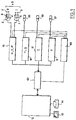
- FIG 2 there is shown an embodiment of a versatile electrotechnical measuring device 1 according to the invention comprising means 2 of electrical connection in parallel and means 3 of electrical connection in series of the device 1 to an electrical circuit (not shown in Figure 2) associated with the electrotechnical machine (not shown in Figure 2) whose characteristics are to be measured by device 1 according to the invention.
- the means 2, 3 for electrical connection comprise three pairs of terminals 3a, 3b, 3c for connection in series for detecting an intensity, and three pairs of terminals 2a, 2b, 2c parallel connection for voltage detection.
- the device 1 is intended only for direct current or alternating single-phase measurements, one could be satisfied with a single pair of connection terminals in series and a single pair of connection terminals in parallel.
- the terminals of a pair of terminals 3, of series connection for detecting an intensity are connected to each other by a primary conductor 5 coupled to a Hall 7 intensity sensor delivering a signal representative of the intensity.
- the terminals of a pair of terminals 2 of parallel connection for detecting a voltage are connected to each other by a primary conductor 4 comprising a resistor 8 in series between these terminals 2, the primary conductor 4 being coupled with a Hall effect intensity sensor 6 delivering a signal representative of the voltage.
- the means 2, 3 for electrical connection consist entirely of pairs of connection terminals 2a, 2b, 2c, 3a, 3b, 3c connected to each other by a conductor primary 4, 5, coupled to a Hall effect intensity sensor 6, 7 which delivers a measurement signal whose instantaneous intensity is a function of the intensity passing through the primary conductor 4, 5.
- the measuring device 1 according to the invention may include other cards for measuring non-purely electrical characteristics.
- the upper part shows means of connection of the device 1 according to the invention to transducers for measuring non-electrical characteristics: a card 9 for measuring temperature, a card 10 for measuring speed and / or sliding, a torque measurement card 11. Other measurement cards can be provided.
- FIG. 2 represents the front face of the measuring device 1 comprising the means of connection to the electrical circuit or to the electrotechnical machine and the various means of control and display of the device.
- the rear face of the device 1 comprises means for connecting this device 1 to a computer processing device 12 such as a microcomputer comprising a display screen 13 and printing means 14 such as a plotter or a printer.
- each Hall effect intensity sensor 6, 7 is a compensated magnetic field sensor providing an analog intensity measurement signal which is in phase with the actual intensity of the current passing through the primary conductor 4, 5.
- a such Hall effect intensity sensor can consist of a device as described in French patent application FR-A-2 608 282 and marketed by the company LEM (Switzerland)
- Each primary conductor 4, 5 is then integrated into the corresponding Hall effect sensor 6, 7.
- Such a Hall effect intensity sensor with zero magnetic field allows measurements both in alternating current and in direct current.
- a resistor 8 of significant value is inserted in series of the primary conductor 4 between the two terminals.
- this resistance is determined so that the current flowing in the primary conductor 4 has a value corresponding to the optimal precision of the sensor for the nominal voltage to be measured.
- the precision of such a sensor is optimal for a current in the primary conductor 4 of the order of 10 milliamps.
- the electrical connection terminals 2, 3 are connection terminals for three wattmeter modules 15 (or a single wattmeter module 15 in the case of use only in single-phase or continuous) .
- Each power module 15 comprises a pair of terminals 2 for connection in parallel with a phase for the detection of a voltage, and a pair of terminals 3 for connection in series with a phase for the detection of an intensity.
- Each power module 15 also includes a circuit 16 for power supplying an analog power signal and comprising an analog multiplier 17 realizing the product of the values of instantaneous analog signals corresponding to the voltage and the intensity coming from Hall effect sensors 6, 7, associated with connection terminals 2, 3.
- the three power modules 15a, 15b, 15c are all identical and each comprise a pair of connection terminals 2a, 2b, 2c in parallel and a pair of connection terminals 3a, 3b, 3c in series. It is thus possible to connect three phases to the measuring device 1 according to the invention.
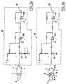
- FIGS. 3a to 3e illustrate electrical diagrams of an embodiment of a power module 15.
- the intensity measurement circuit is shown. This consists of the Hall effect sensor 7 followed by a follower circuit 18 allowing the input impedance to be adapted, then by an amplifier circuit 19.
- the follower circuit is produced with at least one - in particular two - amplifier low drift linear operational differential.
- the first amplifier 108 allows adjustment of the initial offset value and the second 109 allows the output impedance to be lowered.
- the follower circuit 18 includes a measurement resistor 20 and a potentiometer 21 for calibrating the intensity.
- FIG. 3b illustrates a diagram of the voltage measurement circuit.
- This circuit includes the Hall effect sensor 6 connected to the terminals 2 for parallel connection, and comprising its primary conductor 4 with its resistor 8.
- the sensor 6 is also followed by a follower assembly 22 produced in a similar manner to the follower assembly 18 of the intensity measurement circuit previously described.
- the follower assembly 22 also includes a measurement resistor 24 making it possible to adapt the value of the signal as a function of the nominal value to be measured.
- the follower assembly 22 is produced from operational amplifiers 110, 111 linear differential with low drift, with their associated resistances.
- the first operational amplifier 110 allows the correction of the initial effect value and the second 111 makes it possible to adapt the impedance at output.
- the output 25 and respectively 26 of the follower circuits 18 of the intensity measurement circuit, respectively 22 of the voltage measurement circuit delivers instantaneous analog signals in voltage giving images of the intensity, respectively of the voltage measured at the terminals 3, respectively 2 of electrical connection.
- These voltage signals are supplied to the input 27 respectively 28 of a circuit 29 for shaping the intensity signal, respectively 23 for shaping the voltage signal.
- Each wattmeter module 15 also includes a switch 31 making it possible to modify the intensity rating, for example to pass it from 10 to 20 amps, as well as a light diode 32 making it possible to indicate the position of the switch 31. Also , a light-emitting diode 33 indicates that the intensity rating has been exceeded.
- FIG. 3c illustrates an embodiment diagram of the circuit 29 for shaping the intensity signal.
- the switch 31 makes it possible to modify the gain of an operational amplifier 34 of an amplifier assembly 19 placed after the follower assembly 18. When the switch 31 is open, the gain is for example 2, the rating is 10 amps , and the light diode 32 is off. When the switch 31 is closed, the gain of the operational amplifier 34 changes to 1, the rating is 20 amperes and the light diode 32 lights up. Of the so, the analog output 35 of the instantaneous analog intensity signal is always calibrated at 10 volts.
- a full-wave rectifier circuit 36 is used followed by a comparator circuit 37.
- the full-wave rectifier circuit 36 consists of an operational amplifier 38 followed by a diode 39 with a resistor 40 forming a divider of voltage to achieve equality of the rectified amplitudes.
- the full-wave rectifier circuit 36 makes it possible to be able to detect an overshooting of the caliber in a simple manner whatever the nature of the quantity measured, that is to say alternative, continuous positive or continuous negative.
- the output of the comparator circuit 37 turns on the over-caliber diode 33 when the intensity signal exceeds the displayed caliber.
- the comparator circuit 37 also essentially consists of an operational amplifier 41 and a calibration potentiometer 42.
- FIG. 3d illustrates the amplifier assembly 23 disposed at the output of the follower assembly 22, which also makes it possible to supply a voltage signal at output 43 calibrated at 10 volts.
- This amplifier assembly 23 essentially consists of an operational amplifier 44 with its associated resistances, and constitutes the circuit for shaping the analog voltage signal delivered to the analog output 43.
- FIG. 1e illustrates the power circuit 16.
- This power circuit is supplied by the intensity and voltage signals taken upstream of the amplifier circuits 29, 30. More specifically, the voltage input 45 corresponds to the input terminal 28 of the amplifier assembly 23 of the voltage signal , while the input 46 of the intensity signal corresponds to the terminal 47 of the circuit 29 (FIG. 3c) which is connected to the input 27 of the amplifier 19 mounting via a resistor 30.
- the inputs 45, 46 are each followed by two Zener diodes 48, 49 mounted head to tail to protect the analog multiplier 17 against overvoltages.
- the output of the analog multiplier 17 corresponds to a voltage proportional to the instantaneous power, that is to say to the product of the instantaneous voltage by the instantaneous intensity.
- the analog multiplier 17 is followed by a low-pass filter 50 making it possible to determine the average power by eliminating the fluctuating component of the instantaneous power.
- This low-pass filter 50 is itself followed by an amplifier circuit 51 making it possible to have at the output 52 a voltage signal of plus or minus 10 volts providing an image of the power.
- the low-pass filter 50 consists of an operational amplifier 53 and a capacitor 54 with associated resistances allowing the DC component of the input signal to pass.
- the potentiometer 55 is used to calibrate the low-pass filter.
- the amplifier circuit 51 essentially consists of an operational amplifier 56.
- each power module thus constituted provides at 35 a signal of intensity I, in 43 a signal of voltage U, and in 52 a signal of average power P.
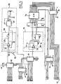
- FIG. 1 illustrates the general construction of the measuring device 1 which comprises a plurality of measuring circuits 9, 10, 11, 15, each measuring circuit comprising means 57, 58, 59, 2, 3 for connection to an electrical circuit or at the output of a non-purely electrical characteristic detection transducer.
- a connection terminal 57 is provided for a thermal probe
- a connection terminal 58 for a rotational speed detector providing pulses. proportional to the speed of rotation
- a connection terminal 59 for the output of a torque measurement transducer which may for example consist of a bridge of strain gauges.
- Each measurement circuit 9, 10, 11, 15 delivers at least one analog measurement signal.
- the device according to the invention comprises means 60, 61 for multiplexing the different analog measurement signals delivered by each measurement circuit.
- the multiplexing means 60, 61 comprise at least one analog multiplexer performing the multiplexing of the analog measurement signals.
- the use of an analog multiplier 17 and analog multiplexers 60, 61 is in particular allowed thanks to the perfect galvanic isolation obtained thanks to Hall effect sensors 6, 7.
- Each measurement circuit 9, 10, 11, 15 is supported by a measurement card, the device 1 according to the invention comprising a plurality of measurement cards 9, 10, 11, 15, each comprising said measurement circuit.
- the device 1 according to the invention also comprises a conversion card 62 comprising the means 60, 61 for multiplexing and means 64, 65, 66 for shaping the signals for a computer processing device 12 and / or display device 13 and / or a plotting device 14.
- the conversion card 62 supplies the signals to the computer processing device 12 which manages the display screen 13 and the plotting device 14
- the means 64, 65, 66 for shaping the signals comprise an analog / digital converter at the output of the means 60, 61 for multiplexing.
- the device 1 comprises three electrical measurement cards 15a, 15b, 15c each comprising a wattmeter module providing an instantaneous analog signal of voltage U1, U2, U3 and intensity I1, I2, I3, and an average power signal P1, P2, P3 to the means 60, 61 for multiplexing the conversion card 62.
- the conversion card 62 comprises means 66 for transforming into instantaneous value instantaneous analog measurement signals - in particular instantaneous voltage and intensity signals U1, U2, U3, I1, 12, I3.
- These means 66 for converting into effective value are arranged at the output of at least one analog multiplexer 60 of the multiplexing means 60, 61, the input of which receives the various signals to be transformed, that is to say the voltages and the electrical currents from the wattmeter measurement cards 15.
- These means 66 for converting into effective value essentially consist of an integrated circuit 67 RMS which performs the transformation of instantaneous signals into equivalent continuous signals.
- the input of this integrated circuit 67 is equipped with a follower assembly 68 consisting of an operational amplifier 69.
- These active components 67, 69 are equipped with the usual associated components allowing in particular the adjustment of the initial offset value and of the sensitivity.
- the measuring device also comprises means 70 for canceling or shunting the means 66 for transforming into effective value.
- these means 70 consist of a switch 70 which makes it possible to bypass the means 66 for transforming into effective value.
- the switch 70 When the switch 70 is closed, the output of the analog multiplexer 60 is directly connected to an input of the second multiplexer 61. In this position, the measurement device according to the invention supplies the microcomputer 12 with voltage and current signals instantaneous and therefore plays the role of a digital oscilloscope.
- Speed, slip, torque, temperature, power or other signals are generally mean or continuous value signals.
- a first multiplexer 60 is therefore provided receiving the instantaneous voltage and intensity value signals U1, U2, U3, I1, I2, I3 and a second multiplexer 61 receiving the signals transmitted in average or continuous value.
- the two multiplexers 60, 61 are connected in cascade, that is to say that the output of the first multiplexer 60 is connected to an input of the second multiplexer 61, by means of transformation into effective value 66 as already said . It is also possible to use a channel of the second multiplexer 61 for transmitting an instant measurement signal to the microcomputer 12. In fact, this second multiplexer 61 is arranged downstream of the means 66 for transforming into effective value.
- the signals received by the second multiplexer 61 are the average power signals P1, P2, P3 of speed n, of slip g, of temperature t, of torque c, or others.
- a follower assembly 71 which also allows an initial offset value adjustment so that the signal is put level at the input of an integrated circuit 72 of analog / digital conversion.
- This integrated circuit 72 with the follower circuit 71 constitutes means 64 for analog / digital conversion of the signal at the output of the means 60, 61 for multiplexing.
- the integrated circuit 72 converts the analog input signal to 12 digital bits which is supplied by the multiplexer 61.
- the follower assembly 71 essentially consists of an operational amplifier 73 with its components associated.
- the digital output signal of the integrated circuit 72 of analog / digital converter is formed on 8 bits intended for the microcomputer 12.
- a buffer memory 74 is provided at the output of the analog / digital converter 72.
- buffer memories 75, 76 are associated with the converter 72 and the multiplexers 60, 61 to facilitate the synchronization which can be carried out from control and timing signals emitted by the microcomputer 12 programmed for this purpose.
- the control and timing signals make it possible in particular to synchronize the analog / digital converter on 12 bits so that the signal can be transmitted on a bus of 8 bits successively on 8 bits and on 4 bits.
- the digital signal at the output 77 of the analog / digital conversion means 64 is supplied via an interface circuit 65 to the microcomputer 12.
- the interface circuit 65 is adapted as a function of the microcomputer 12 used and is therefore constituted simply an input / output card compatible with this microcomputer 12.
- FIG. 6 illustrates an electronic diagram for producing a torque measurement card 11 of a device 1 according to the invention.
- This card makes it possible to use a continuous voltage variation coming from a measurement bridge with strain gauges glued on a steel test tube itself mounted on the rotating electrotechnical machine such as a motor in order to measure the torque. .
- the gauge bridge 78 (which is not an integral part of the measurement card 11 itself although it is shown in FIG. 6) is supplied with fixed direct voltage thanks to a voltage reference 79 providing a direct voltage not fluctuating with temperature.
- the voltage reference 79 is composed of a stabilized power supply 105 of an operational amplifier 106 and of a transistor 107 which allows the supply of current with a high intensity.
- the gauge bridge 78 emits a signal which is immediately amplified by an operational amplifier 81 with high input impedance. At the output of this operational amplifier 81, a low-pass filter 8é0, the cut-off frequency of which is 1 hertz, suppresses all the parasitic alternating voltages.
- this voltage signal is supplied at 83 to a display voltmeter 84 on the front face of the measuring device 1 according to the invention.
- an operational amplifier 85 with high input impedance supplies an analog output 86 with a voltage signal of plus or minus 10 volts. It is this analog output signal 86 which is supplied to the multiplexer 61 of the conversion card 62.
- FIG. 7 illustrates the block diagram of an embodiment of a speed and slip measurement card of a measurement device according to the invention.
- This card makes it possible to measure the speed of an electrotechnical rotating machine and to display the speed and the slip on display means 87, respectively 88 of the front face of the measuring device 1.
- This card 10 for measuring the speed of rotation and sliding comprises a microcontroller 89.
- Input means 90 make it possible to input and transmit to the microcontroller 89 the synchronization speed of the rotating machine and the number of pulses per revolution of the machine.
- These input means 90 can consist for example of jumpers or switches making it possible to select for example the speed between four synchronization speeds such as 750, 1000, 1500 or 3000 revolutions per minute.
- the speed of the rotating machine can be measured using a disc drilled on its periphery with 1 or 60 holes and driven in rotation with the axis of the machine.
- An optoelectronic device sends a signal at 91 in the form of pulses whose frequency corresponds to the speed of rotation. These pulses are shaped in a circuit 92 which transforms the analog pulses into square signals for the microcontroller 89 which counts the pulses every second.
- the circuit 93 is a time base supplied to the microcontroller 89.
- the digital signal supplied by the microcontroller 89 is supplied to a digital analog converter 94 which provides an analog signal of the speed at 95.
- the signal is also supplied to a digital converter / digital 96 which transforms the digital speed signal into a digital slip signal.
- This converter 96 can consist of a simple EPROM memory containing the different possible values of synchronism speed.
- the microcontroller 89 supplies this converter 96 with an address code corresponding to the synchronization speed entered, so that this converter 96 transforms the digital code under 12 input bits of the speed into a binary code on 8 bits of the slip. Indeed, the slip is expressed in a percentage between minus 9.9% and plus 9.9%.
- the digital slip signal is then supplied to a digital / analog converter 97 which supplies at output 98 the signal intended for the multiplexer 61 of the conversion card 62.
- the digital signal emitted by the microcontroller 89 can be directly supplied to means 99, respectively 100 for converting the signal for display means 87 of the speed, respectively 88 slip.
- EPROM memories can be used for this, the address buses of which are connected in parallel.
- the measuring device 1 also comprises a card 9 for measuring temperature or another characteristic produced in a similar manner.
- Other measurement cards can be provided in a nonlimiting manner, and the possibilities of the device 1 according to the invention are almost limitless in this regard. From a certain number of measurement cards, it may possibly be necessary to multiply the conversion cards 62 and to arrange them in cascade.
- a power supply card 101 is provided to supply the voltages plus 5 volts, plus 15 volts to the user and the DC voltages 0 volts, plus and minus 5 volts, plus and minus 15 volts to the various circuits of the cards.
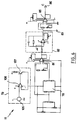
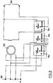
- FIG. 8 illustrates an example of the use of a device 1 according to the invention in the case of a three-phase synchronous machine.
- the three-phase 400-volt network is supplied at 102 on three phases and a neutral N.
- the power modules 15a, 15b, 15c are connected as shown in FIG. 8 between the network 102 and the machine 103.
- the 220-volt DC network 104 is connected to the wattmeter module 15c.
- the wattmeter module 15a measures the active power P
- the wattmeter module 15b measures the reaction power Q
- the wattmeter module 15c measures the excitation power.
Landscapes
- Physics & Mathematics (AREA)
- General Physics & Mathematics (AREA)
- Measurement Of Current Or Voltage (AREA)
Applications Claiming Priority (2)
| Application Number | Priority Date | Filing Date | Title |
|---|---|---|---|
| FR9206443 | 1992-05-26 | ||
| FR9206443A FR2691806B1 (fr) | 1992-05-26 | 1992-05-26 | Dispositif de mesure electrotechnique polyvalent. |
Publications (1)
| Publication Number | Publication Date |
|---|---|
| EP0572319A1 true EP0572319A1 (de) | 1993-12-01 |
Family
ID=9430204
Family Applications (1)
| Application Number | Title | Priority Date | Filing Date |
|---|---|---|---|
| EP93401346A Withdrawn EP0572319A1 (de) | 1992-05-26 | 1993-05-26 | Elektrotechnisches Mehrfach-Messinstrument |
Country Status (2)
| Country | Link |
|---|---|
| EP (1) | EP0572319A1 (de) |
| FR (1) | FR2691806B1 (de) |
Cited By (1)
| Publication number | Priority date | Publication date | Assignee | Title |
|---|---|---|---|---|
| CN100376897C (zh) * | 2005-12-21 | 2008-03-26 | 淄博计保互感器研究所 | 一种能适应计量、测量或保护需要的高压信号取样方法 |
Citations (3)
| Publication number | Priority date | Publication date | Assignee | Title |
|---|---|---|---|---|
| WO1987006352A1 (en) * | 1986-04-09 | 1987-10-22 | Müller Und Weigert Gmbh | Multimeter |
| GB2198543A (en) * | 1986-12-12 | 1988-06-15 | Lem Liaisons Electron Mec | Current sensors |
| EP0432386A1 (de) * | 1989-12-14 | 1991-06-19 | Landis & Gyr Business Support AG | Anordnung zur Ermittlung von Werten elektrischer Grössen, die von Messwerten mindestens zweier elektrischer Eingangsgrössen der Anordnung ableitbar sind |
-
1992
- 1992-05-26 FR FR9206443A patent/FR2691806B1/fr not_active Expired - Lifetime
-
1993
- 1993-05-26 EP EP93401346A patent/EP0572319A1/de not_active Withdrawn
Patent Citations (3)
| Publication number | Priority date | Publication date | Assignee | Title |
|---|---|---|---|---|
| WO1987006352A1 (en) * | 1986-04-09 | 1987-10-22 | Müller Und Weigert Gmbh | Multimeter |
| GB2198543A (en) * | 1986-12-12 | 1988-06-15 | Lem Liaisons Electron Mec | Current sensors |
| EP0432386A1 (de) * | 1989-12-14 | 1991-06-19 | Landis & Gyr Business Support AG | Anordnung zur Ermittlung von Werten elektrischer Grössen, die von Messwerten mindestens zweier elektrischer Eingangsgrössen der Anordnung ableitbar sind |
Non-Patent Citations (4)
| Title |
|---|
| CONFERENCE RECORD OF THE 1987 IEEE INDUSTRY APPLICATIONS SOCIETY ANNUAL MEETING vol. I, Octobre 1987, ATLANTA, GEORGIA US pages 391 - 402 S.MUKHERJEE ET AL. 'Digital Measurement of the Efficiency of Inverter-Induction Machines' * |
| ELECTRONIC DESIGN. vol. 34, no. 9, Avril 1986, HASBROUCK HEIGHTS, NEW JERSEY US pages 165 - 172 D.R.TAYLOR 'Power-supply efficiency can be measured by one instrument, not many' * |
| IEEE TRANSACTIONS ON POWER SYSTEMS vol. 3, no. 3, Août 1988, NEW YORK US pages 1328 - 1334 A.KEYHANI ET AL 'Microcomputer-Aided Data Acquisition System for Laboratory Testing of Transformers and Electrical Machines' * |
| REVUE GENERALE DE L'ELECTRICITE no. 5, Mai 1984, PARIS FR pages 283 - 287 J.-P. ETTER 'Méthodes modernes de mesure des courants. 1 - Le capteur LEM' * |
Cited By (1)
| Publication number | Priority date | Publication date | Assignee | Title |
|---|---|---|---|---|
| CN100376897C (zh) * | 2005-12-21 | 2008-03-26 | 淄博计保互感器研究所 | 一种能适应计量、测量或保护需要的高压信号取样方法 |
Also Published As
| Publication number | Publication date |
|---|---|
| FR2691806A1 (fr) | 1993-12-03 |
| FR2691806B1 (fr) | 1996-04-05 |
Similar Documents
| Publication | Publication Date | Title |
|---|---|---|
| FR3019303B1 (fr) | Dispositif de mesure d'au moins une grandeur physique d'une installation electrique | |
| EP0117790B1 (de) | Wirbelstrom-Multispulen-Sensor versehen mit einer Spulenausgleichvorrichtung | |
| FR2474799A1 (fr) | Systeme d'acquisition de donnees et convertisseur analogique-numerique | |
| EP3126854B1 (de) | Verfahren zur messung des energieverbrauchs der verzweigungen eines elektrischen netzwerks und messvorrichtung zur implementierung des verfahrens | |
| FR2624802A1 (fr) | Codage de la valeur de plusieurs grandeurs mesurees dans un pneumatique | |
| FR2497956A1 (fr) | Dispositif et procede pour la detection de la composante continue d'une courbe alternative | |
| EP0128865A1 (de) | Verfahren zur Verbesserung der Dämpfung bei der Stillegung eines Polyphasenmotors, insbesondere eines Schrittmotors, und Anordnung für die Durchführung des Verfahrens | |
| EP0293310A1 (de) | Verfahren zum Kalibrieren eines elektronischen Drehmomentschlüssels | |
| FR2754063A1 (fr) | Circuit de multiplication de resolution et de determination de sens de deplacement | |
| EP2877824B1 (de) | Selbstkalibrierender kalorimeter mithilfe von elektrischer substitution | |
| EP1038349B1 (de) | Regelungsvorrichtung für einen elektrischen motor | |
| EP0572319A1 (de) | Elektrotechnisches Mehrfach-Messinstrument | |
| EP0489665A1 (de) | Anordnung zur Isolationskontrolle mit erhöhter Genauigkeit | |
| FR2679648A1 (fr) | Transmetteur analogique de position et de sens de rotation. | |
| FR2509098A1 (fr) | Dispositif de protection de moteur a courant alternatif | |
| EP0628828B1 (de) | Mess- und Zählvorrichtung für elektrische Energie | |
| EP0162990B1 (de) | Einwegmesskopf und Fernmessgerät mit einem solchen Kopf | |
| EP0554188B1 (de) | Gerät zur Messung elektrischer Grössen | |
| FR2536223A1 (fr) | Dispositif pour alimenter en forte tension continue un appareil electrique consommateur | |
| FR2732834A1 (fr) | Dispositif de controle angulaire d'un moteur pas a pas | |
| FR2565695A1 (fr) | Procede et dispositif de mesure de la composante reactive d'une impedance complexe | |
| EP0101773A1 (de) | Verfahren und Vorrichtung zur Messung des Schlupfes eines Motors | |
| EP0353156A1 (de) | Eingangsschaltung eines programmierbaren Automaten vom "alles oder nichts"-Typ | |
| EP4567437A1 (de) | Messung der phase einer komplexen impedanz durch schwellenwert | |
| EP0616292A1 (de) | Multiplizierschaltung mit Widerstandsnetzwerken und einem diese Schaltung enthaltenden Elektrizitätszähler |
Legal Events
| Date | Code | Title | Description |
|---|---|---|---|
| PUAI | Public reference made under article 153(3) epc to a published international application that has entered the european phase |
Free format text: ORIGINAL CODE: 0009012 |
|
| AK | Designated contracting states |
Kind code of ref document: A1 Designated state(s): BE CH DE ES GB IT LI NL PT |
|
| 17P | Request for examination filed |
Effective date: 19940311 |
|
| STAA | Information on the status of an ep patent application or granted ep patent |
Free format text: STATUS: THE APPLICATION IS DEEMED TO BE WITHDRAWN |
|
| 18D | Application deemed to be withdrawn |
Effective date: 19961203 |