EP0572242B1 - Improved method and appartus for adaptive deadtime process control - Google Patents
Improved method and appartus for adaptive deadtime process control Download PDFInfo
- Publication number
- EP0572242B1 EP0572242B1 EP93304096A EP93304096A EP0572242B1 EP 0572242 B1 EP0572242 B1 EP 0572242B1 EP 93304096 A EP93304096 A EP 93304096A EP 93304096 A EP93304096 A EP 93304096A EP 0572242 B1 EP0572242 B1 EP 0572242B1
- Authority
- EP
- European Patent Office
- Prior art keywords
- signal
- variable signal
- filter
- noise
- deadtime
- Prior art date
- Legal status (The legal status is an assumption and is not a legal conclusion. Google has not performed a legal analysis and makes no representation as to the accuracy of the status listed.)
- Expired - Lifetime
Links
- 238000000034 method Methods 0.000 title claims description 69
- 238000004886 process control Methods 0.000 title description 11
- 230000003044 adaptive effect Effects 0.000 title description 10
- 230000008569 process Effects 0.000 claims description 47
- 230000008859 change Effects 0.000 claims description 9
- 238000012545 processing Methods 0.000 claims description 3
- 238000005070 sampling Methods 0.000 claims description 3
- 230000006978 adaptation Effects 0.000 claims 6
- 238000001914 filtration Methods 0.000 claims 6
- 241000269627 Amphiuma means Species 0.000 claims 1
- 230000001276 controlling effect Effects 0.000 description 3
- 230000000694 effects Effects 0.000 description 3
- 238000012421 spiking Methods 0.000 description 3
- 238000004519 manufacturing process Methods 0.000 description 2
- 238000012544 monitoring process Methods 0.000 description 2
- 230000004044 response Effects 0.000 description 2
- 238000007792 addition Methods 0.000 description 1
- 239000007844 bleaching agent Substances 0.000 description 1
- 230000003247 decreasing effect Effects 0.000 description 1
- 230000003111 delayed effect Effects 0.000 description 1
- 238000013461 design Methods 0.000 description 1
- 239000012467 final product Substances 0.000 description 1
- 239000012530 fluid Substances 0.000 description 1
- 230000010354 integration Effects 0.000 description 1
- 239000007788 liquid Substances 0.000 description 1
- 238000007620 mathematical function Methods 0.000 description 1
- 238000005259 measurement Methods 0.000 description 1
- 230000001343 mnemonic effect Effects 0.000 description 1
- 238000012986 modification Methods 0.000 description 1
- 230000004048 modification Effects 0.000 description 1
- 230000001105 regulatory effect Effects 0.000 description 1
- 230000011664 signaling Effects 0.000 description 1
- 239000002002 slurry Substances 0.000 description 1
- 230000007704 transition Effects 0.000 description 1
- 238000011144 upstream manufacturing Methods 0.000 description 1
Images


Classifications
-
- G—PHYSICS
- G05—CONTROLLING; REGULATING
- G05B—CONTROL OR REGULATING SYSTEMS IN GENERAL; FUNCTIONAL ELEMENTS OF SUCH SYSTEMS; MONITORING OR TESTING ARRANGEMENTS FOR SUCH SYSTEMS OR ELEMENTS
- G05B11/00—Automatic controllers
- G05B11/01—Automatic controllers electric
- G05B11/36—Automatic controllers electric with provision for obtaining particular characteristics, e.g. proportional, integral, differential
- G05B11/42—Automatic controllers electric with provision for obtaining particular characteristics, e.g. proportional, integral, differential for obtaining a characteristic which is both proportional and time-dependent, e.g. P. I., P. I. D.
-
- G—PHYSICS
- G05—CONTROLLING; REGULATING
- G05B—CONTROL OR REGULATING SYSTEMS IN GENERAL; FUNCTIONAL ELEMENTS OF SUCH SYSTEMS; MONITORING OR TESTING ARRANGEMENTS FOR SUCH SYSTEMS OR ELEMENTS
- G05B13/00—Adaptive control systems, i.e. systems automatically adjusting themselves to have a performance which is optimum according to some preassigned criterion
- G05B13/02—Adaptive control systems, i.e. systems automatically adjusting themselves to have a performance which is optimum according to some preassigned criterion electric
- G05B13/04—Adaptive control systems, i.e. systems automatically adjusting themselves to have a performance which is optimum according to some preassigned criterion electric involving the use of models or simulators
- G05B13/042—Adaptive control systems, i.e. systems automatically adjusting themselves to have a performance which is optimum according to some preassigned criterion electric involving the use of models or simulators in which a parameter or coefficient is automatically adjusted to optimise the performance
Definitions
- the invention relates to process control and, more particularly, to improved deadtime process control apparatus and methods.
- Process control refers to the control of the operational parameters of a process by monitoring one or more of its characteristics over time. It is used to ensure that the quality and efficiency of a process do not vary substantially during a single run or over the course of several runs. Process control has application in both the manufacturing and service sectors.
- a process control unit typically operates by monitoring and comparing a process characteristic, the controlled variable, with a desired "setpoint" level to determine whether the process is operating within acceptable bounds. As the controlled variable begins to deviate, the controller manipulates one of the process inputs, the manipulated variable, to bring the process back to the desired level of activity.
- a process controller can oversee a process in which fluid flows at a constant rate from a continuously refilled tank.
- the controller monitors the liquid level in the tank and, when necessary to prevent the tank from running dry or overflowing, adjusts an inlet valve to increase or restrict the inflow.
- controllers developed by the art are those in which the manipulated variable signal is generated as a predetermined mathematical function of the controlled variable.
- One such controller, illustrated in Figure 2a, is the proportional-integral-derivative (PID) controller.
- PID proportional-integral-derivative
- the manipulated variable is generated as a function of the "error,” that is, the difference between the controlled variable and the setpoint: where,
- SU-A-1,287,104 describes an adaptive regulator with regulated feedback comprising a PID regulator with switches connecting three linear filters to increase stability and improve the quality of regulation.
- model-based controllers which model, mathematically, the operation of the process.
- One such controller is the deadtime controller, which relies on a model of the process deadtime and lag to determine values for the manipulated variable. See, for example, MEASUREMENT AND CONTROL vol. 23, no. 4, May 1990, LONDON GB pages 114-121; F. SHINSKEY 'HOW GOOD ARE OUR CONTROLLERS IN ABSOLUTE PERFORMANCE AND ROBUSTNESS' which describes a method and apparatus for controlling a process according to the preamble of claims 1 and 7, respectively.
- Deadtime is the time it takes a change in the manipulated variable to be reflected by a change in the controlled variable. For example, in a paper making process, deadtime is the time it takes for a change in the bleaching agent added to the initial slurry to be detected by a photo sensor that measures the whiteness of the final product web.
- Lag is the time, after the deadtime period, that it takes the controlled variable to move approximately 63% of its final value, following a step change in the manipulated variable.
- a deadtime controller of the type referred to above is shown in Figure 2b. It is constructed by adding a "deadtime element,” i.e., a time delay, into the integral feedback loop of a PID controller. This controller is referred to by the mnemonic "PID ⁇ d .”
- an object of this invention to provide improved methods and apparatus for process control. More particularly, an object is to provide improved PID ⁇ d deadtime controllers.
- Still another object is to provide a deadtime controller capable of accurately and efficiently controlling deadtime dominant processes.
- the method and controller according to the present invention is characterized by the features of the characterizing portions of claims 1 and 7, respectively.
- the invention which provides, in one aspect, a deadtime controller, based on a PID ⁇ d design, which incorporates an adaptive noise filter in the output path, upstream from the feedback to the integration section.
- the invention provides an adaptive PIDTd controller having a proportional derivative section that generates an error signal representing an error in the control signal, particularly, as a function of (i) a time rate of change of the controlled variable signal and (ii) a difference between the controlled variable signal and a predetermined setpoint.
- a summation element sums that error signal with a time-delayed integral signal to generate a summation signal. That summation signal, in turn, is filtered by the aforementioned adaptive noise filter to generate a manipulated variable signal, which is selectively applied to the process by an output section.
- a feedback element processes the manipulated variable signal to generate the time-delayed integral signal, referred to above. That processing includes time-delaying the manipulated variable signal an amount substantially equal to the deadtime of the process, ⁇ d , and passing that time-delayed manipulated variable signal through a first-order lag of time constant I to generate the time-delayed integral signal.
- the adaptive noise filter varies the filter time constant to maintain the level of noise in the manipulated variable signal at a predetermined level.
- the filter time constant can be limited to a pre-selected range between 0 and 0.1 * ⁇ d .
- Still other aspects of the invention include methods for process control in accord with the operations described above.
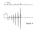
- the controlled variable, c experiences an initial rapid increase of value in response to an applied step load (not shown) on the process.
- the controller compensates for the disturbance, the controlled variable converges toward the setpoint, s, which is represented by the horizontal axis.
- the controller output represented by manipulated variable signal, m, responds to the initial change in the controlled variable by rapidly decreasing in value. As the controlled variable begins returning toward the setpoint, the manipulated variable, too, returns to its normal value, n. Because of the mismatch between the deadtime constants of the process and controller, however, the manipulated variable signal begins to spike at each transition. These spikes, which increase in magnitude, effect changes in the process itself, as reflected in spiking of the controlled variable signal.
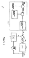
- FIG. 4 depicts an adaptive PID ⁇ d controller according to the invention. Aspects of the controller 10 are constructed and operated in accord with a conventional PID ⁇ d controller, as particularly modified in accord with the discussion which follows.
- the controller 10 includes a proportional-derivative section 12 that accepts as inputs the controlled variable signal, c, and a desired setpoint.
- the controlled variable signal can be generated in a manner conventional to the art, for example, by measuring equipment coupled with the process itself.
- the setpoint too, can be generated in a conventional manner, e.g., via the operator at a console (not shown).
- the proportional-derivative section 12 operates in a manner like that of the corresponding section of a conventional PID ⁇ d controller.
- the section 12 generates a PD signal representative of an error in the controlled variable signal, c, particularly, as a function of a time rate of change of the controlled variable and a difference between it and the setpoint.
- the gain of proportional-derivative section 12 can be set in a conventional manner. Preferably, however, the gain of that section 12 (and, accordingly, that of the illustrated controller 10) is set in accord with the teachings of related application United States Patent Application No. 889,474, for METHOD AND APPARATUS FOR TUNING PROCESS CONTROL EQUIPMENT (Attorney Docket No. 10226).
- Illustrated integral control element 14 and deadtime element 16 together, generate a signal, ID, representing a time-wise integral of a time delayed form of the manipulated variable signal, m. These elements, too, operate in a manner like that of the corresponding elements of a conventional PID ⁇ d controller. More particularly, the deadtime section 16 time-delays the manipulated variable signal, m, by the controller deadtime ⁇ d . The integral control section, 14, integrates that time-delayed signal with a time constant I.
- a summation section 18 sums the PD signal generated by the PD section 12 with the ID signal generated by the integral control 14.
- the output of element 18 is passed through filter 20, having a time constant ⁇ f , which attenuates high frequency components of the summed signal.
- the filtered signal can be passed through high and low limits 22, which limits the filtered signal to limit integral windup.
- the signal output by filter 20, and optionally limited by limiter unit 22, is applied to the process as manipulated variable signal m. That signal is fed back to the integral control and deadtime elements 14, 16, as illustrated, for production of the signal ID.
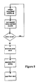
- the controller 10 automatically adjusts the filter time constant ⁇ f to maintain the level of noise, ⁇ m , in the manipulated variable signal at a predetermined level, ⁇ set .
- step 30 the controller 10 samples values of the manipulated variable signal, m.
- step 31 the controller sums values of m, as well as squares of those values.
- step 33 the controller determines whether to sample more output values, preferably, so as to obtain a full set of samples over the period of a complete controller deadtime ⁇ d .
- the controller determines the noise level of the manipulated variable signal; see step 34.
- step 36 the controller limits the value of the filter time constant, ⁇ f , between the values 0 and 0.1 * ⁇ d .
- Figure 6 illustrates the operation of an adaptive PID ⁇ d controller according to the invention in controlling a first-order deadtime dominant process.
- the controller deadtime is initally greater than that of the process.
- the level of noise in the manipulated variable signal can be determined by processes other than that described above.
Landscapes
- Engineering & Computer Science (AREA)
- Physics & Mathematics (AREA)
- General Physics & Mathematics (AREA)
- Automation & Control Theory (AREA)
- Health & Medical Sciences (AREA)
- Artificial Intelligence (AREA)
- Computer Vision & Pattern Recognition (AREA)
- Evolutionary Computation (AREA)
- Medical Informatics (AREA)
- Software Systems (AREA)
- Feedback Control In General (AREA)
Description
Claims (12)
- A method for controlling a process that has a characteristic that can be measured by a controlled variable signal and that responds to a manipulated variable signal for varying that characteristic, said method comprising:A. generating an PD signal (PD) indicative of an error in said controlled variable signal (C), said generating step including determining said PD signal (PD) as a function of a time rate of change of said controlled variable signal (C) and a difference between said controlled variable signal (C) and a predetermined setpoint,B. summing said PD signal (PD) and a time-delayed integral signal to generate a summation signal, andc. selectively applying said manipulated variable signal (M) to said process, the method being characterized by:D. filtering said summation signal, with a filter time constant τf to generate a manipulated variable signal (M), andE. feeding-back said manipulated variable signal (M) to generate said time-delayed integral signal, said feed-back step includingi) time-delaying said manipulated variable signal (M) an amount substantially equal to a deadtime, τd, andii) passing that time-delayed manipulated variable signal through a first-order lag of time constant I to generate said time-delayed integral signal.
- A method according to claim 1, wherein said filtering step comprisesA. sampling noise in said manipulated variable signal (M) to generate a signal, σm, representative of a level thereof, andB. varying said filter time constant τf to maintain said noise at a selected level, σset.
- A method according to claim 2, wherein said filtering step includes generating said noise level signal, σm, as a function of noise value sampled over a time period substantially equal to said deadtime constant τd.
- A method according to claim 2, wherein said filtering step comprises an adaptation step for generating said filter time constant τf as a function of said deadtime constant τf and a ratio of said noise level σm to said setpoint σset.
- A method according to claim 4, wherein said filtering step comprises generating said noise level signal, σm, as a function of (i) a sum of sampled values of said noise and (ii) a sum of squares of those sampled values of said noise.
- A method according to claim 4 or claim 5, wherein said adaptation step includes generating said filter time constant τf as a function of a mathematical relation
- A proportional-integral-derivative deadtime process controller for measuring a controlled variable signal (C) representative of a first characteristic of a process, and for applying a manipulated variable signal (M) to that process to vary that first characteristic, said controller comprisingA. proportional derivative means (12) for generating an PD signal (PD) indicative of an error in said controlled variable signal (C), said proportional derivative means including means for generating said PD signal (PD) as a function of a time rate of change of said controlled variable signal (C) and a difference between said controlled variable signal (C) and a predetermined setpoint,B. summation means (18), coupled with said proportional derivative means (12), for summing said PD signal (PD) and a time-delayed integral signal to generate a summation signal, andC. controlled variable signal output means for selectively applying said manipulated variable signal (M) to said process, characterized by:D. noise filter means (20), coupled with said summation means (18), for filtering said summation signal to generate a manipulated variable signal, (M), said noise filter means (20) having a filter time constant τf, and said filter means (20) for instance being a second-order Butterworth filter or a first-order low-pass filter, andE. feedback means, coupled to said controlled variable signal output means, for processing said manipulated variable signal (M) to generate said time-delayed integral signal, said processing includingi) time-delaying said manipulated variable signal (M) an amount substantially equal to a deadtime, τd, andii) passing that time-delayed manipulated variable signal through a first-order lag of time constant I to generate said time-delayed integral signal.
- A proportional-integral-derivative, deadtime process controller according to claim 7, wherein said noise filter means (20) comprisesA. means for sampling noise in said manipulated variable signal to generate a signal, σm, representative of a level thereof, andB. means for varying said filter time constant τf to maintain said noise at a selected level, σset.
- A proportional-integral-derivative deadtime process controller according to claim 8, wherein said noise filter means (20) includes means for generating said noise level signal, σm, for a time period substantially equal to said deadtime constant τd.
- A proportional-integral-derivative deadtime process controller according to claim 8, wherein said noise filter means (20) comprises adaptation means for generating said filter time constant τf as a function of said deadtime constant τd and a ratio of said noise level σm to said setpoint σset.
- A proportional-integral-derivative deadtime process controller according to claim 10, wherein said noise filter means (20) comprises means for generating said noise level signal, σm, as a function of (i) a sum of sampled values of said controller output and (ii) a sum of squares of those sampled values of said controller output.
- A proportional-integral-derivative deadtime process controller according to claim 11, wherein said adaptation means includes means for generating said filter time constant τf as a function of a mathematical relation
Applications Claiming Priority (2)
| Application Number | Priority Date | Filing Date | Title |
|---|---|---|---|
| US889473 | 1992-05-27 | ||
| US07/889,473 US5335165A (en) | 1992-05-27 | 1992-05-27 | Method and apparatus for adaptive deadtime process control |
Publications (3)
| Publication Number | Publication Date |
|---|---|
| EP0572242A2 EP0572242A2 (en) | 1993-12-01 |
| EP0572242A3 EP0572242A3 (en) | 1994-02-16 |
| EP0572242B1 true EP0572242B1 (en) | 1998-07-22 |
Family
ID=25395177
Family Applications (1)
| Application Number | Title | Priority Date | Filing Date |
|---|---|---|---|
| EP93304096A Expired - Lifetime EP0572242B1 (en) | 1992-05-27 | 1993-05-26 | Improved method and appartus for adaptive deadtime process control |
Country Status (3)
| Country | Link |
|---|---|
| US (1) | US5335165A (en) |
| EP (1) | EP0572242B1 (en) |
| DE (1) | DE69319795T2 (en) |
Families Citing this family (8)
| Publication number | Priority date | Publication date | Assignee | Title |
|---|---|---|---|---|
| DE19711156A1 (en) * | 1997-03-18 | 1998-09-24 | Mannesmann Rexroth Ag | Adaptation algorithm for a controller |
| US5848535A (en) * | 1997-03-24 | 1998-12-15 | Gas Research Institute | Control system having a binomial setpoint filter |
| JPH10306801A (en) * | 1997-05-01 | 1998-11-17 | Smc Corp | Control method of automatic control pneumatic apparatus |
| DE19960796C5 (en) * | 1998-12-17 | 2009-09-10 | Nissan Motor Co., Ltd., Yokohama-shi | Electromagnetically actuated valve control device and method for controlling an electromagnetically operable valve |
| US6445980B1 (en) * | 1999-07-10 | 2002-09-03 | Mykrolis Corporation | System and method for a variable gain proportional-integral (PI) controller |
| US6247678B1 (en) * | 1999-11-01 | 2001-06-19 | Swagelok Company | Shape memory alloy actuated fluid control valve |
| US8200347B2 (en) * | 2009-01-22 | 2012-06-12 | Mitsubishi Electric Research Laboratories, Inc. | Method and apparatus for hybrid resetting states proportional-integral-derivative and lag controllers |
| JP5553876B2 (en) | 2012-10-17 | 2014-07-16 | 株式会社神戸製鋼所 | Non-localized control device with dead time |
Family Cites Families (25)
| Publication number | Priority date | Publication date | Assignee | Title |
|---|---|---|---|---|
| US3515860A (en) * | 1967-11-06 | 1970-06-02 | Industrial Nucleonics Corp | Process controller with dynamic set-point adjustment responsive to the statistical variance of the controlled property |
| US3617717A (en) * | 1969-04-28 | 1971-11-02 | Westinghouse Electric Corp | Optimizing control systems |
| US3671725A (en) * | 1970-10-01 | 1972-06-20 | Ibm | Dead time process regulation |
| US3786242A (en) * | 1971-09-23 | 1974-01-15 | H Brooks | Process control simulator |
| US3876872A (en) * | 1971-10-14 | 1975-04-08 | Industrial Nucleonics Corp | Process control system and method with integral-action set-point optimization using statistically-variable gain control responsive to fraction defective |
| US3995478A (en) * | 1972-06-09 | 1976-12-07 | Industrial Nucleonics Corporation | Plural interrelated set point controller |
| US3867712A (en) * | 1972-06-28 | 1975-02-18 | Honeywell Inc | Adaptive filter |
| US3961234A (en) * | 1972-12-29 | 1976-06-01 | General Electric Company | Adaptive filtering |
| US3992616A (en) * | 1975-06-24 | 1976-11-16 | Honeywell Inc. | Receiver equalizer apparatus |
| US4186384A (en) * | 1975-06-24 | 1980-01-29 | Honeywell Inc. | Signal bias remover apparatus |
| JPS5465274A (en) * | 1977-11-04 | 1979-05-25 | Hideji Hayashibe | Device of automatically adjusting pid value of regulator |
| US4346433A (en) * | 1980-03-11 | 1982-08-24 | Phillips Petroleum Company | Process control |
| SU932461A1 (en) * | 1980-06-06 | 1982-05-30 | Всесоюзное научно-производственное объединение целлюлозно-бумажной промышленности | Adaptive control system |
| SU1012202A2 (en) * | 1982-01-08 | 1983-04-15 | Одесский Технологический Институт Холодильной Промышленности | Extremum regulator |
| USRE33267E (en) * | 1983-12-12 | 1990-07-17 | The Foxboro Company | Pattern-recognizing self-tuning controller |
| US4602326A (en) * | 1983-12-12 | 1986-07-22 | The Foxboro Company | Pattern-recognizing self-tuning controller |
| US4654811A (en) * | 1985-02-12 | 1987-03-31 | Allied Corporation | Adaptive filter for aircraft navigation receiver |
| DE3811086A1 (en) * | 1987-04-03 | 1988-10-20 | Hitachi Ltd | PID CONTROL SYSTEM |
| US4855897A (en) * | 1987-07-13 | 1989-08-08 | The Foxboro Company | Method and apparatus for statistical set point bias control |
| US4959767A (en) * | 1988-11-23 | 1990-09-25 | Elsag International B.V. | Parameter estimation technique for closed loop system |
| US5150317A (en) * | 1989-01-11 | 1992-09-22 | The Boeing Company | Adaptive digital filter which is responsive to the rate of change of an input signal |
| CA2014252A1 (en) * | 1989-06-27 | 1990-12-27 | Sang Pak | Analog to digital input operating system |
| US5091844A (en) * | 1989-11-06 | 1992-02-25 | Waltz Albert J | Preemptive constraint control |
| US5191521A (en) * | 1990-06-18 | 1993-03-02 | Controlsoft, Inc. | Modular multivariable control apparatus and method |
| US5124626A (en) * | 1990-12-20 | 1992-06-23 | Mts Systems Corporation | Sinusoidal signal amplitude and phase control for an adaptive feedback control system |
-
1992
- 1992-05-27 US US07/889,473 patent/US5335165A/en not_active Expired - Lifetime
-
1993
- 1993-05-26 DE DE69319795T patent/DE69319795T2/en not_active Expired - Lifetime
- 1993-05-26 EP EP93304096A patent/EP0572242B1/en not_active Expired - Lifetime
Also Published As
| Publication number | Publication date |
|---|---|
| DE69319795T2 (en) | 1999-04-15 |
| DE69319795D1 (en) | 1998-08-27 |
| US5335165A (en) | 1994-08-02 |
| EP0572242A2 (en) | 1993-12-01 |
| EP0572242A3 (en) | 1994-02-16 |
Similar Documents
| Publication | Publication Date | Title |
|---|---|---|
| DE69311314T2 (en) | ADAPTIVE PATTERN DETECTION CONTROLLER | |
| US5748467A (en) | Method of adapting and applying control parameters in non-linear process controllers | |
| US4602326A (en) | Pattern-recognizing self-tuning controller | |
| EP0572242B1 (en) | Improved method and appartus for adaptive deadtime process control | |
| US5166873A (en) | Process control device | |
| DE69020919T2 (en) | Method and device for changing control parameters according to the state of the process in the area of process control. | |
| EP0159103B1 (en) | Process control apparatus | |
| DE10231417B4 (en) | Model-free adaptation of a process controller (process control unit) | |
| RU2185649C2 (en) | Method of cut-in of independent control with prediction in multivariant forecasting controller | |
| DE69823633T2 (en) | Nonlinear model-based predictive control method for controlling a gas phase reactor. | |
| US5587896A (en) | Self-tuning controller | |
| US6330484B1 (en) | Method and apparatus for fuzzy logic control with automatic tuning | |
| US20020040250A1 (en) | Auto-tuning controller using loop-shaping | |
| USRE33267E (en) | Pattern-recognizing self-tuning controller | |
| EP0572244B1 (en) | Method and apparatus for tuning process control equipment | |
| US5420785A (en) | Self-tuning deadtime process controller | |
| US5341288A (en) | Method and apparatus for analyzing process characteristics | |
| DE3620614A1 (en) | METHOD FOR FILTERING A NOISY SIGNAL | |
| US5428527A (en) | Method and device for the consideration of varying volume and flow in the control of a continuous flow process | |
| Rice et al. | Design and tuning of PID controllers for integrating (non-self regulating) processes | |
| Swanda et al. | Evaluating the performance of PID-type feedback control loops using normalized settling time | |
| EP0307466B1 (en) | Multivariable adaptive feedforward controller | |
| DE69305608T2 (en) | Regulation of two-stage valves | |
| EP0610189B1 (en) | An improved self-tuning controller | |
| Tsang et al. | A new approach to auto-tuning of PID controllers |
Legal Events
| Date | Code | Title | Description |
|---|---|---|---|
| PUAI | Public reference made under article 153(3) epc to a published international application that has entered the european phase |
Free format text: ORIGINAL CODE: 0009012 |
|
| AK | Designated contracting states |
Kind code of ref document: A2 Designated state(s): DE FR GB |
|
| PUAL | Search report despatched |
Free format text: ORIGINAL CODE: 0009013 |
|
| AK | Designated contracting states |
Kind code of ref document: A3 Designated state(s): DE FR GB |
|
| 17P | Request for examination filed |
Effective date: 19940711 |
|
| 17Q | First examination report despatched |
Effective date: 19960801 |
|
| GRAG | Despatch of communication of intention to grant |
Free format text: ORIGINAL CODE: EPIDOS AGRA |
|
| GRAG | Despatch of communication of intention to grant |
Free format text: ORIGINAL CODE: EPIDOS AGRA |
|
| GRAH | Despatch of communication of intention to grant a patent |
Free format text: ORIGINAL CODE: EPIDOS IGRA |
|
| GRAH | Despatch of communication of intention to grant a patent |
Free format text: ORIGINAL CODE: EPIDOS IGRA |
|
| GRAA | (expected) grant |
Free format text: ORIGINAL CODE: 0009210 |
|
| AK | Designated contracting states |
Kind code of ref document: B1 Designated state(s): DE FR GB |
|
| REF | Corresponds to: |
Ref document number: 69319795 Country of ref document: DE Date of ref document: 19980827 |
|
| ET | Fr: translation filed | ||
| PLBE | No opposition filed within time limit |
Free format text: ORIGINAL CODE: 0009261 |
|
| STAA | Information on the status of an ep patent application or granted ep patent |
Free format text: STATUS: NO OPPOSITION FILED WITHIN TIME LIMIT |
|
| 26N | No opposition filed | ||
| REG | Reference to a national code |
Ref country code: GB Ref legal event code: IF02 |
|
| REG | Reference to a national code |
Ref country code: FR Ref legal event code: CD |
|
| REG | Reference to a national code |
Ref country code: GB Ref legal event code: 732E |
|
| REG | Reference to a national code |
Ref country code: FR Ref legal event code: GC |
|
| REG | Reference to a national code |
Ref country code: GB Ref legal event code: 732E |
|
| PGFP | Annual fee paid to national office [announced via postgrant information from national office to epo] |
Ref country code: DE Payment date: 20120531 Year of fee payment: 20 |
|
| PGFP | Annual fee paid to national office [announced via postgrant information from national office to epo] |
Ref country code: GB Payment date: 20120426 Year of fee payment: 20 Ref country code: FR Payment date: 20120510 Year of fee payment: 20 |
|
| REG | Reference to a national code |
Ref country code: DE Ref legal event code: R071 Ref document number: 69319795 Country of ref document: DE |
|
| REG | Reference to a national code |
Ref country code: GB Ref legal event code: PE20 Expiry date: 20130525 |
|
| PG25 | Lapsed in a contracting state [announced via postgrant information from national office to epo] |
Ref country code: GB Free format text: LAPSE BECAUSE OF EXPIRATION OF PROTECTION Effective date: 20130525 Ref country code: DE Free format text: LAPSE BECAUSE OF EXPIRATION OF PROTECTION Effective date: 20130528 |