EP0572010A2 - Vessel level sensor mounting structure with positive mechanical lock - Google Patents
Vessel level sensor mounting structure with positive mechanical lock Download PDFInfo
- Publication number
- EP0572010A2 EP0572010A2 EP93108595A EP93108595A EP0572010A2 EP 0572010 A2 EP0572010 A2 EP 0572010A2 EP 93108595 A EP93108595 A EP 93108595A EP 93108595 A EP93108595 A EP 93108595A EP 0572010 A2 EP0572010 A2 EP 0572010A2
- Authority
- EP
- European Patent Office
- Prior art keywords
- vessel
- fitting member
- level sensor
- mounting structure
- outer fitting
- Prior art date
- Legal status (The legal status is an assumption and is not a legal conclusion. Google has not performed a legal analysis and makes no representation as to the accuracy of the status listed.)
- Withdrawn
Links
- 239000012530 fluid Substances 0.000 claims abstract description 12
- 238000004891 communication Methods 0.000 claims abstract description 4
- 239000007788 liquid Substances 0.000 claims description 8
- 230000003247 decreasing effect Effects 0.000 claims 3
- 239000000835 fiber Substances 0.000 claims 2
- 238000007789 sealing Methods 0.000 claims 2
- 238000000034 method Methods 0.000 description 5
- 238000013459 approach Methods 0.000 description 4
- 239000002131 composite material Substances 0.000 description 4
- 230000007423 decrease Effects 0.000 description 3
- 239000000463 material Substances 0.000 description 3
- 239000002699 waste material Substances 0.000 description 2
- XLYOFNOQVPJJNP-UHFFFAOYSA-N water Substances O XLYOFNOQVPJJNP-UHFFFAOYSA-N 0.000 description 2
- 230000000295 complement effect Effects 0.000 description 1
- 238000005516 engineering process Methods 0.000 description 1
- 238000009434 installation Methods 0.000 description 1
Images

Classifications
-
- B—PERFORMING OPERATIONS; TRANSPORTING
- B64—AIRCRAFT; AVIATION; COSMONAUTICS
- B64D—EQUIPMENT FOR FITTING IN OR TO AIRCRAFT; FLIGHT SUITS; PARACHUTES; ARRANGEMENT OR MOUNTING OF POWER PLANTS OR PROPULSION TRANSMISSIONS IN AIRCRAFT
- B64D11/00—Passenger or crew accommodation; Flight-deck installations not otherwise provided for
- B64D11/02—Toilet fittings
-
- G—PHYSICS
- G01—MEASURING; TESTING
- G01F—MEASURING VOLUME, VOLUME FLOW, MASS FLOW OR LIQUID LEVEL; METERING BY VOLUME
- G01F23/00—Indicating or measuring liquid level or level of fluent solid material, e.g. indicating in terms of volume or indicating by means of an alarm
-
- G—PHYSICS
- G01—MEASURING; TESTING
- G01F—MEASURING VOLUME, VOLUME FLOW, MASS FLOW OR LIQUID LEVEL; METERING BY VOLUME
- G01F23/00—Indicating or measuring liquid level or level of fluent solid material, e.g. indicating in terms of volume or indicating by means of an alarm
- G01F23/22—Indicating or measuring liquid level or level of fluent solid material, e.g. indicating in terms of volume or indicating by means of an alarm by measuring physical variables, other than linear dimensions, pressure or weight, dependent on the level to be measured, e.g. by difference of heat transfer of steam or water
- G01F23/28—Indicating or measuring liquid level or level of fluent solid material, e.g. indicating in terms of volume or indicating by means of an alarm by measuring physical variables, other than linear dimensions, pressure or weight, dependent on the level to be measured, e.g. by difference of heat transfer of steam or water by measuring the variations of parameters of electromagnetic or acoustic waves applied directly to the liquid or fluent solid material
- G01F23/296—Acoustic waves
- G01F23/2968—Transducers specially adapted for acoustic level indicators
Definitions
- the present invention relates to structures used for mounting a liquid level sensor in a liquid containing vessel such as a waste tank or water tank like those used on aircraft.
- liquid level sensors such as one using sonar techniques or other electronic sensors, at an appropriate location to enable the sensor to periodically provide a reading of the liquid level in the tank.
- the vessels contain pressures which are higher or lower than the surrounding ambient pressure.
- the sensor can either be sucked into the vessel (when the vessel contains a pressure which is lower than the ambient pressure) or blown out of the vessel (when the vessel contains a pressure which is higher than the ambient pressure).
- a leak at a pressure sensor mounting can impair the intended function of a vessel, a catastrophic failure such as a level sensor being blown out of, or sucked into, the vessel can be extremely dangerous, particularly in an aircraft.
- the present invention provides a level sensor mounting structure particularly adapted for use with vessels containing pressure above or below the ambient pressure surrounding the vessel.
- the embodiments of the present invention provide a positive mechanical lock between the vessel and the level sensor ensuring that the level sensor will not be blown out of, or sucked into, the vessel even if the fluid tight seal between the mounting structures and the vessel wall fails.
- first and second fitting members are provided which are installed on the vessel at an opening provided thereon.
- the first fitting member is positioned on the interior of the vessel and includes a laterally extending flange.
- the laterally extending flange is configured to bond and seal to the interior surface of the vessel.
- the second fitting member is positioned on the exterior of the vessel.
- the second fitting member also has a laterally extending flange which is configured to bond and seal to the exterior surface of the vessel.
- bolts are used to mechanically lock the first fitting member and the second fitting member together such that the vessel wall is held captive between the flanges provided on the fitting members.
- the second, outer fitting member is provided with a recess into which the level sensor fits so the level sensor is in communication with the interior of the vessel.
- the second fitting member is provided with an outwardly extending lip with an inclined surface.
- a cover with a complementary inclined surface is positioned over the level sensor.
- a V-band clamp having corresponding inclined surfaces is preferably used to engage the inclined surfaces on the cover and the lip. As the V-band clamp is tightened, the cover pushes on the level sensor to provide a fluid tight seal between the level sensor and the second fitting member and a positive mechanical lock between the level sensor and the vessel wall.
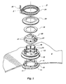
- FIG. 1 provides an exploded perspective view of a vessel wall 2.
- An opening 4 has been provided in the vessel wall 2 into which a level sensor 20 is to be mounted.
- the level sensor 20 can be any one of a number available in the art using any of the available technologies. Generally, all such level sensors require that they be periodically removed from the vessel for repair or replacement.
- FIG. 1 Represented in Figure 1 at 21 are a plurality of bores which are provided about the perimeter of the level sensor 20.
- the bores 21 are not used in connection with the present invention but are customarily provided on level sensors to mount the same in accordance with previously used techniques.
- bolts or studs are passed through the bores 21 in accordance with previously used techniques and also through bores (not illustrated) provided in a vessel wall and nuts are tightened thereon to hold the level sensor 20, is time consuming and may be prone to problems such as difficult removal of the level sensor.
- the vessel wall 2 may be part of a vacuum or pressure containing vessel such as those used on aircraft or in other applications. Such vessels are often fabricated from composite materials because of their high strength and light weight.
- the present invention has application in any number of situations involving containers which must have some type of sensor mounted in the wall thereof.
- An inner fitting member 10 is positioned on the interior of the vessel wall 2 at the opening 4.
- a plurality of threaded bores 11 are provided on a raised collar portion of the inner fitting member 10.
- the raised collar portion of the inner fitting member 10 fits within the diameter of the opening 4 in the vessel wall 2 and ensures that the inner fitting member remains in position at the opening 4 even if the fluid tight seal between the mounting structures and the vessel wall 2 is broken.
- the inner fitting member 10 be molded from compatible materials using techniques known in the art.
- the inner fitting member 10 is bonded to the interior of the vessel wall 2 using techniques known in the art. It is the bond between the inner fitting member 10 and the interior of the vessel wall 2 which provides a fluid tight seal between the two structures.
- additional structures provide what is referred to herein as a "mechanical lock" to ensure that if a failure of the fluid tight bond occurs, the mounting structures and the level sensor 20 will not be blown out of, or sucked into, the vessel.
- An outer fitting member 12 is shown in Figure 1 positioned above the exterior surface of the vessel wall 2.
- the outer fitting member 12 is provided with a raised lip 13 and a plurality of bores 15.
- the outer fitting member 12 is preferably molded from a material which is compatible with composite materials or whatever materials are used to fabricate the vessel wall 2.
- the outer fitting member 12 be bonded to the exterior of the vessel wall 2.
- care should be used to ensure that the bores 15 of the outer fitting member 12 line up with the threaded bores 11 provided on the inner fitting member 10.
- an O ring is preferably provided to ensure a fluid tight seal between the recessed surface provided in the outer fitting member 12 and the level sensor 20. While the use of the O ring 16 in the location illustrated in Figure 2 is preferred, it is to be appreciated that other structures and arrangements could also be used to provide a fluid tight seal between the level sensor 20 and the outer fitting member 12.
- a gasket 18 is placed over the perimeter of the level sensor 20 and a cover 22 is placed over the gasket 18.
- a V band clamp 24 is positioned and tightened over the raised lip 13 of the outer fitting member 12 and the cover 22.
- FIG 2 the cross sectional shape of the V band clamp 24 can be seen.
- the sideways V shape of the V band clamp 24 engages the inclined planes on the cover 22 and the raised lip 13 provided on the outer fitting member 12 so that as the circumference of the V band clamp decreases, the cover 22 is pushed toward the outer fitting member 12.
- the V-band clamp 24 includes a threaded handle 26 which, as it is rotated, causes the circumference of the V-band clamp 24 to increase or decrease. As the circumference of the V-band clamp 24 decreases, and the cover 22 is forced toward the outer fitting member 12, a fluid tight seal between the level sensor 20 and the outer fitting member 12 is formed.
- the V-band clamp 24 further provides a positive mechanical lock which ensure that the level sensor 20 will not be blown out of, or sucked into, the vessel.
- connection providing the positive mechanical lock between the inner fitting member 10 and the outer fitting member 12 is provided within the diameter of the opening 4 in the vessel wall 2. This advantageously allows the positive mechanical lock to be provided without cutting any additional holes in the vessel wall 2.
- Figure 2 also shows that the inner fitting member 10, the outer fitting member 12, and the cover 22 all are dimensioned such that they do not make contact with many of the structures of the level sensor 20 which could cause difficulties with the operation or removal of the level sensor 20.
- the present invention provides a vessel level sensor mounting structure with a positive mechanical lock which prevents the level sensor from being blown out of, or sucked into, the pressure vessel in the event of a seal failure and which is simple and easy to use.
- the present invention also provides a vessel level sensor mounting structure which reduces the likelihood of breakage of any part of the structure during removal of the sensor and which requires only one opening for the level sensor be provided in the vessel wall.
Landscapes
- Physics & Mathematics (AREA)
- Fluid Mechanics (AREA)
- General Physics & Mathematics (AREA)
- Acoustics & Sound (AREA)
- Electromagnetism (AREA)
- Thermal Sciences (AREA)
- Engineering & Computer Science (AREA)
- Aviation & Aerospace Engineering (AREA)
- Measurement Of Levels Of Liquids Or Fluent Solid Materials (AREA)
Abstract
Description
- The present invention relates to structures used for mounting a liquid level sensor in a liquid containing vessel such as a waste tank or water tank like those used on aircraft.
- In many types of liquid containers and tanks, including water tanks and waste tanks used on aircraft, it is important to periodically monitor the liquid level in the tank, for example, to prevent overflow, to recognize when refilling is necessary, and so forth. This is done typically by mounting some type of liquid level sensor, such as one using sonar techniques or other electronic sensors, at an appropriate location to enable the sensor to periodically provide a reading of the liquid level in the tank.
- One previously used approach to mounting such level sensors involves the forming of an opening in the tank wall at the appropriate location, inserting the sensor into the opening with a flange provided on the sensor preventing the sensor from dropping into the tank, and then securing the sensor in place in the opening with studs or bolts inserted through bores in the flange. Another approach is described in U.S. Patent No. 5,065,392 to Lukez. The Lukez reference provides an extension which is bonded to the tank wall. A band clamp is then used to secure the sensor to the extension. The band clamp can be readily applied and removed allowing the sensor to be easily replaced.
- It is often the case that the vessels contain pressures which are higher or lower than the surrounding ambient pressure. In the case of these described approaches, and other known approaches, if a component fails the sensor can either be sucked into the vessel (when the vessel contains a pressure which is lower than the ambient pressure) or blown out of the vessel (when the vessel contains a pressure which is higher than the ambient pressure). While a leak at a pressure sensor mounting can impair the intended function of a vessel, a catastrophic failure such as a level sensor being blown out of, or sucked into, the vessel can be extremely dangerous, particularly in an aircraft. Thus, it would be an advance in the art to provide an improved level sensor mounting structure for use in vessels.
- In view of the above described state of the art, the present invention seeks to realize the following objects and advantages.
- It is an object of the present invention to provide a vessel level sensor mounting structure which provides a positive mechanical lock which prevents the level sensor from being blown out of, or sucked into, the pressure vessel.
- It is also an object of the present invention to provide a simple and easy to use structure for mounting a liquid level sensor in a vessel.
- It is a further object of the present invention to provide a vessel level sensor mounting structure which allows for the easy removal and reinstallation of the level sensor while mechanically securing the level sensor in place even if a failure of the pressure seal between the level sensor and the vessel occurs.
- It is an additional object of the present invention to provide a vessel level sensor mounting structure which reduces the likelihood of breakage of any part of the structure during removal and installation of the level sensor.
- It is a further object of the present invention to provide a vessel level sensor mounting structure which does not require cutting bolt holes in the vessel wall.
- These and other objects and advantages of the invention will become more fully apparent from the description and claims which follow, or may be learned by the practice of the invention.
- The present invention provides a level sensor mounting structure particularly adapted for use with vessels containing pressure above or below the ambient pressure surrounding the vessel. The embodiments of the present invention provide a positive mechanical lock between the vessel and the level sensor ensuring that the level sensor will not be blown out of, or sucked into, the vessel even if the fluid tight seal between the mounting structures and the vessel wall fails.
- In the preferred embodiments of the present invention, first and second fitting members are provided which are installed on the vessel at an opening provided thereon. The first fitting member is positioned on the interior of the vessel and includes a laterally extending flange. The laterally extending flange is configured to bond and seal to the interior surface of the vessel.
- The second fitting member is positioned on the exterior of the vessel. The second fitting member also has a laterally extending flange which is configured to bond and seal to the exterior surface of the vessel. In the preferred embodiments of the invention, bolts are used to mechanically lock the first fitting member and the second fitting member together such that the vessel wall is held captive between the flanges provided on the fitting members.
- The second, outer fitting member is provided with a recess into which the level sensor fits so the level sensor is in communication with the interior of the vessel. The second fitting member is provided with an outwardly extending lip with an inclined surface. A cover with a complementary inclined surface is positioned over the level sensor. A V-band clamp having corresponding inclined surfaces is preferably used to engage the inclined surfaces on the cover and the lip. As the V-band clamp is tightened, the cover pushes on the level sensor to provide a fluid tight seal between the level sensor and the second fitting member and a positive mechanical lock between the level sensor and the vessel wall.
- In order to better appreciate how the above-recited and other advantages and objects of the invention are obtained, a more particular description of the invention briefly described above will be rendered by reference to a specific embodiment thereof which is illustrated in the appended drawings. Understanding that these drawings depict only a typical embodiment of the invention and are not therefore to be considered limiting of its scope, the invention will be described and explained with additional specificity and detail through the use of the accompanying drawings in which:
- Figure 1 is an exploded perspective view of the presently preferred embodiment of the level sensor mounting structure of the present invention positioned on the wall of a vessel.
- Figure 2 is a cross sectional view of the vessel level sensor mounting structure illustrated in Figure 1 assembled in place on the vessel wall.
- Reference will now be made to the drawings wherein like structures will be provided with like reference designations.
- Figure 1 provides an exploded perspective view of a
vessel wall 2. An opening 4 has been provided in thevessel wall 2 into which alevel sensor 20 is to be mounted. Thelevel sensor 20 can be any one of a number available in the art using any of the available technologies. Generally, all such level sensors require that they be periodically removed from the vessel for repair or replacement. - Represented in Figure 1 at 21 are a plurality of bores which are provided about the perimeter of the
level sensor 20. Thebores 21 are not used in connection with the present invention but are customarily provided on level sensors to mount the same in accordance with previously used techniques. Disadvantageously, when bolts or studs are passed through thebores 21 in accordance with previously used techniques and also through bores (not illustrated) provided in a vessel wall and nuts are tightened thereon to hold thelevel sensor 20, is time consuming and may be prone to problems such as difficult removal of the level sensor. - The
vessel wall 2 may be part of a vacuum or pressure containing vessel such as those used on aircraft or in other applications. Such vessels are often fabricated from composite materials because of their high strength and light weight. The present invention, however, has application in any number of situations involving containers which must have some type of sensor mounted in the wall thereof. - An
inner fitting member 10 is positioned on the interior of thevessel wall 2 at the opening 4. A plurality of threadedbores 11 are provided on a raised collar portion of theinner fitting member 10. The raised collar portion of theinner fitting member 10 fits within the diameter of the opening 4 in thevessel wall 2 and ensures that the inner fitting member remains in position at the opening 4 even if the fluid tight seal between the mounting structures and thevessel wall 2 is broken. - When the
vessel wall 2 is fabricated using composite materials, it is preferred that theinner fitting member 10 be molded from compatible materials using techniques known in the art. Theinner fitting member 10 is bonded to the interior of thevessel wall 2 using techniques known in the art. It is the bond between theinner fitting member 10 and the interior of thevessel wall 2 which provides a fluid tight seal between the two structures. As will be explained shortly, additional structures provide what is referred to herein as a "mechanical lock" to ensure that if a failure of the fluid tight bond occurs, the mounting structures and thelevel sensor 20 will not be blown out of, or sucked into, the vessel. - An
outer fitting member 12 is shown in Figure 1 positioned above the exterior surface of thevessel wall 2. Theouter fitting member 12 is provided with a raisedlip 13 and a plurality ofbores 15. As in the case of theinner fitting member 10, theouter fitting member 12 is preferably molded from a material which is compatible with composite materials or whatever materials are used to fabricate thevessel wall 2. - When composite materials are used to fabricate the
vessel 2, it is preferred that theouter fitting member 12 be bonded to the exterior of thevessel wall 2. When the outer fittingmember 12 is bonded into place, care should be used to ensure that thebores 15 of the outer fittingmember 12 line up with the threaded bores 11 provided on the innerfitting member 10. - With both the inner
fitting member 10 and the outer fittingmember 12 bonded in place on thevessel wall 2, a fluid tight seal is provided therebetween and the mounting structures are ready to receive thelevel sensor 20. In order to ensure a positive mechanical lock between the mounting structures and thevessel wall 2, a plurality ofbolts 14 are inserted through thebores 15 and tightened into the threaded bores 11. Thus, not only are the inner and outer fitting members bonded to the vessel wall but are also provided with a positive mechanical lock thereto. The relationship of the twofitting members vessel wall 2 can readily be seen in the cross sectional view of Figure 2. - Referring to both Figures 1 and 2, an O ring is preferably provided to ensure a fluid tight seal between the recessed surface provided in the outer fitting
member 12 and thelevel sensor 20. While the use of theO ring 16 in the location illustrated in Figure 2 is preferred, it is to be appreciated that other structures and arrangements could also be used to provide a fluid tight seal between thelevel sensor 20 and the outer fittingmember 12. - Once the
level sensor 18 is placed into the outer fittingmember 12, agasket 18 is placed over the perimeter of thelevel sensor 20 and acover 22 is placed over thegasket 18. With theO ring 16,level sensor 20,gasket 22, and cover 24 in place on the outer fittingmember 12 as shown in Figure 2, aV band clamp 24 is positioned and tightened over the raisedlip 13 of the outer fittingmember 12 and thecover 22. - In Figure 2 the cross sectional shape of the
V band clamp 24 can be seen. The sideways V shape of theV band clamp 24 engages the inclined planes on thecover 22 and the raisedlip 13 provided on the outer fittingmember 12 so that as the circumference of the V band clamp decreases, thecover 22 is pushed toward the outer fittingmember 12. - The V-
band clamp 24 includes a threadedhandle 26 which, as it is rotated, causes the circumference of the V-band clamp 24 to increase or decrease. As the circumference of the V-band clamp 24 decreases, and thecover 22 is forced toward the outer fittingmember 12, a fluid tight seal between thelevel sensor 20 and the outer fittingmember 12 is formed. The V-band clamp 24 further provides a positive mechanical lock which ensure that thelevel sensor 20 will not be blown out of, or sucked into, the vessel. - As can be seen best in Figure 2, the connection providing the positive mechanical lock between the inner
fitting member 10 and the outer fittingmember 12 is provided within the diameter of the opening 4 in thevessel wall 2. This advantageously allows the positive mechanical lock to be provided without cutting any additional holes in thevessel wall 2. Figure 2 also shows that the innerfitting member 10, the outer fittingmember 12, and thecover 22 all are dimensioned such that they do not make contact with many of the structures of thelevel sensor 20 which could cause difficulties with the operation or removal of thelevel sensor 20. - It will be appreciated that the present invention provides a vessel level sensor mounting structure with a positive mechanical lock which prevents the level sensor from being blown out of, or sucked into, the pressure vessel in the event of a seal failure and which is simple and easy to use. The present invention also provides a vessel level sensor mounting structure which reduces the likelihood of breakage of any part of the structure during removal of the sensor and which requires only one opening for the level sensor be provided in the vessel wall.
- The present invention may be embodied in other specific forms without departing from its spirit or essential characteristics. The described embodiment is to be considered in all respects only as illustrative and not restrictive. The scope of the invention is, therefore, indicated by the appended claims rather than by the foregoing description. All changes which come within the meaning and range of equivalency of the claims are to be embraced within their scope.
- What is claimed and desired to be secured by United States Letters Patent is:
Claims (12)
- A level sensor mounting structure for use with vessels having a wall, the mounting structure comprising:
a first fitting member having a first laterally extending flange, the first laterally extending flange configured to seal against the interior surface of the vessel at an opening in the wall thereof;
a second fitting member having a second laterally extending flange, the second laterally extending flange configured to seal against the exterior surface of the vessel at the opening thereof, the second fitting member having a recess into which the level sensor fits and a lip positioned about the recess;
means for mechanically locking the first fitting member and the second fitting member together such that the wall of the vessel lies between the first laterally extending flange and the second laterally extending flange and cannot be removed therefrom without breaking the integrity of the first or second fitting members or the wall of the vessel; and
clamp means for substantially surrounding the perimeter of the level sensor and for releasably holding the level sensor in the recess by pushing the level sensor in the direction of the lip on the second fitting member such that the level sensor is exposed to the interior of the vessel and is positively mechanically locked in place in the opening. - A level sensor mounting structure as defined in claim 1 wherein the first fitting member comprises an inner fitting member and the means for mechanically locking the first fitting member comprises a plurality of fastener receptacles provided on the surface of the inner fitting member facing outward from the interior of the vessel.
- A level sensor mounting structure as defined in claim 2 wherein the second fitting member comprises an outer fitting member and the means for mechanically locking the first fitting member and the second fitting member together further comprises a plurality of fasteners and a plurality of bores in the outer fitting member, the fasteners passing through said bores, the bores being placed in alignment with the fastener receptacles provided on the inner fitting member.
- A level sensor mounting structure as defined in claim 1 further comprising a sonar level sensor.
- A level sensor mounting structure as defined in claim 1 wherein the first fitting member is bonded to the interior surface of the vessel and wherein the second fitting member is bonded to the exterior surface of the vessel.
- A level sensor mounting structure as defined in claim 1 wherein the second fitting member comprises a raised lip having an inclined surface and wherein the clamp means comprises:
a V-band clamp which reduces its circumference when tightened;
a level sensor cover having an inclined surface, the V-band clamp engaging the inclined surface on the cover and on the lip such that as the circumference of the V-band clamp is decreased, the cover and the level sensor is pushed toward the interior of the vessel to form a fluid tight seal. - A level sensor mounting structure for use with pressure containing vessels having a wall and an opening therein, the mounting structure comprising:
an inner fitting member having a surface capable of being sealed to the inner surface of the vessel and a bore coincident with the opening in the vessel when the inner fitting member is sealed to the inner surface of the vessel;
an outer fitting member having a surface capable of being sealed to the outer surface of the vessel and a bore coincident with the opening in the vessel when the outer fitting member is sealed to the outer surface of the vessel, the outer fitting member provided with a first inclined plane about its perimeter;
a plurality of bores provided in the inner and outer fitting members;
a plurality of fasteners passing through the plurality of bores in the inner and outer fitting members and through the opening in the vessel, said fasteners holding the inner and outer fitting members in a tight relationship and holding the vessel wall captive therebetween;
a cover having a second inclined plane provided thereon and sized to substantially cover at least a portion of the perimeter of the level sensor; and
a V-band clamp of a size to engage the first inclined plane and the second inclined plane within its perimeter such that as the perimeter of the V-band clamp is reduced, the cover member is pushed toward the outer fitting member and the level sensor is placed in sealed communication with the interior of the vessel and the level sensor having a positive mechanical lock to the vessel wall. - A level sensor mounting structure as defined in claim 7 further comprising a vessel fabricated as a fiber wound vessel and wherein the vessel contains a pressure greater than the ambient pressure and wherein the inner fitting member is bonded to the interior of the vessel and the outer fitting member is bonded to the exterior of the vessel.
- A level sensor mounting structure as defined in claim 7 further comprising a vessel fabricated as a fiber wound vessel and wherein the vessel contains a pressure less than the ambient pressure and wherein the inner fitting member is bonded to the interior of the vessel and the outer fitting member is bonded to the exterior of the vessel.
- A level sensor mounting structure as defined in claim 7 further comprising a resilient sealing member positioned between the outer fitting member and the level sensor and wherein the fasteners comprise a plurality of bolts.
- A level sensor mounting structure as defined in claim 7 wherein the V-band clamp comprises two inclined surfaces each configured to contact one of the inclined surfaces on the cover and the outer fitting member such that as the diameter of the V-band clamp is decreased the contact area between the inclined surfaces increases.
- A level sensor mounting structure for use with liquid containing vessels having a wall with an opening therein and a level sensor having a flange extending therefrom, the mounting structure comprising:
an inner fitting member;
a flange extending laterally from the inner fitting member;
a plurality of fastener receptacles provided on the inner fitting member in an area which is not greater than the area of the opening in the wall;
an outer fitting member;
a flange extending laterally from the outer fitting member;
a plurality of fasteners passing through the outer fitting member and being received by the fastener receptacles such that the vessel wall is held captive between the flanges of the outer and inner fitting members;
a raised lip having a tapered surface thereon and extending outwardly from the outer fitting member;
sealing means for providing a fluid tight surface between the outer fitting member and the level sensor;
a cover having a tapered surface thereon and configured to cover at least a portion of the perimeter of the level sensor; and
a V-band clamp sized to engage the tapered surfaces on the lip and on the cover such that as the V-band clamp is tightened and its perimeter is decreased, force is placed on the tapered surfaces and the cover member is pushed toward the outer fitting member and the level sensor is placed in sealed communication with the interior of the vessel and the level sensor has a positive mechanical lock to the vessel wall and allowing for ready removal of the level sensor when the V-band clamp is loosened.
Applications Claiming Priority (2)
| Application Number | Priority Date | Filing Date | Title |
|---|---|---|---|
| US07/890,985 US5201222A (en) | 1992-05-29 | 1992-05-29 | Vessel level sensor mounting structure with positive mechanical lock |
| US890985 | 1992-05-29 |
Publications (2)
| Publication Number | Publication Date |
|---|---|
| EP0572010A2 true EP0572010A2 (en) | 1993-12-01 |
| EP0572010A3 EP0572010A3 (en) | 1994-12-14 |
Family
ID=25397423
Family Applications (1)
| Application Number | Title | Priority Date | Filing Date |
|---|---|---|---|
| EP93108595A Withdrawn EP0572010A3 (en) | 1992-05-29 | 1993-05-27 | Vessel level sensor mounting structure with positive mechanical lock. |
Country Status (4)
| Country | Link |
|---|---|
| US (1) | US5201222A (en) |
| EP (1) | EP0572010A3 (en) |
| JP (1) | JPH06323888A (en) |
| CA (1) | CA2096694A1 (en) |
Cited By (2)
| Publication number | Priority date | Publication date | Assignee | Title |
|---|---|---|---|---|
| DE29721863U1 (en) * | 1997-12-10 | 1999-02-04 | Siemens AG, 80333 München | Arrangement for installing a sensor |
| US6773678B2 (en) | 2000-03-20 | 2004-08-10 | Endress + Hauser Conducta Gesellschaft Fur Mess Und Regeltechnik Mbh + Co. | Mounting system and retractable sensor holder for analytical sensors |
Families Citing this family (9)
| Publication number | Priority date | Publication date | Assignee | Title |
|---|---|---|---|---|
| DE19538677C2 (en) * | 1995-10-17 | 1998-12-17 | Endress Hauser Gmbh Co | Arrangement for monitoring a predetermined fill level of a liquid in a container |
| US6412344B1 (en) * | 1999-11-15 | 2002-07-02 | Rosemount Aerospace Inc. | Fluid level sensor with dry couplant |
| US6925869B2 (en) * | 2003-01-28 | 2005-08-09 | The Boeing Company | Ultrasonic fuel-gauging system |
| JP4613667B2 (en) * | 2005-03-31 | 2011-01-19 | セイコーエプソン株式会社 | Liquid detection device, liquid container, and manufacturing method of liquid detection device |
| KR100648301B1 (en) * | 2005-09-14 | 2006-11-24 | (주)지오엘리먼트 | Canister with capacitive level sensor for the special chemical |
| US20070285228A1 (en) * | 2006-06-09 | 2007-12-13 | Fortson Frederick O | Retrofit sensors with wireless communication capabilities |
| US9926956B2 (en) | 2016-02-19 | 2018-03-27 | Cummins Emission Solutions Inc. | Dual purpose clamp for securing aftertreatment housing joints |
| US9968188B1 (en) | 2016-07-11 | 2018-05-15 | Engineered Network Systems, Llc | Locking base for tablet stand |
| US20220260170A1 (en) * | 2019-08-27 | 2022-08-18 | Mag Aerospace Industries, Llc | Ball valve for aircraft tank |
Citations (3)
| Publication number | Priority date | Publication date | Assignee | Title |
|---|---|---|---|---|
| GB2195445A (en) * | 1986-09-29 | 1988-04-07 | Endress Hauser Gmbh Co | An ultrasonic or sonic filling level measuring device for measuring the filling level of explosive or aggressive media in a container |
| GB2204405A (en) * | 1987-04-27 | 1988-11-09 | Marconi Gec Ltd | Acoustic sensor apparatus for detecting sludge in a storage tank |
| US5065892A (en) * | 1990-08-27 | 1991-11-19 | Edo Corporation | Structure for mounting liquid level sensors and the like in liquid containers |
Family Cites Families (6)
| Publication number | Priority date | Publication date | Assignee | Title |
|---|---|---|---|---|
| US3307400A (en) * | 1964-08-27 | 1967-03-07 | Roy Gene Le | Sight glass for reaction vessels |
| US3407662A (en) * | 1966-05-16 | 1968-10-29 | Jacoby Tarbox Corp | Sight glass mounting and adjusting means |
| JPS53138192A (en) * | 1977-05-07 | 1978-12-02 | Shiyouichi Uno | Method of transporting commodities utilizing independent engine boat and method of deposit and reservation on sea of transported and received commodities utilizing cargo boat |
| US4221004A (en) * | 1978-08-03 | 1980-09-02 | Robertshaw Controls Company | Adjustable ultrasonic level measurement device |
| JPS564176A (en) * | 1979-06-25 | 1981-01-17 | Mochida Shiyoukou Kk | Stop indicator |
| US4981040A (en) * | 1989-11-22 | 1991-01-01 | Jack Lin | Sight flow indication apparatus with multi-sealing protective arrangements |
-
1992
- 1992-05-29 US US07/890,985 patent/US5201222A/en not_active Expired - Fee Related
-
1993
- 1993-05-20 CA CA002096694A patent/CA2096694A1/en not_active Abandoned
- 1993-05-27 EP EP93108595A patent/EP0572010A3/en not_active Withdrawn
- 1993-05-28 JP JP5127342A patent/JPH06323888A/en active Pending
Patent Citations (3)
| Publication number | Priority date | Publication date | Assignee | Title |
|---|---|---|---|---|
| GB2195445A (en) * | 1986-09-29 | 1988-04-07 | Endress Hauser Gmbh Co | An ultrasonic or sonic filling level measuring device for measuring the filling level of explosive or aggressive media in a container |
| GB2204405A (en) * | 1987-04-27 | 1988-11-09 | Marconi Gec Ltd | Acoustic sensor apparatus for detecting sludge in a storage tank |
| US5065892A (en) * | 1990-08-27 | 1991-11-19 | Edo Corporation | Structure for mounting liquid level sensors and the like in liquid containers |
Cited By (2)
| Publication number | Priority date | Publication date | Assignee | Title |
|---|---|---|---|---|
| DE29721863U1 (en) * | 1997-12-10 | 1999-02-04 | Siemens AG, 80333 München | Arrangement for installing a sensor |
| US6773678B2 (en) | 2000-03-20 | 2004-08-10 | Endress + Hauser Conducta Gesellschaft Fur Mess Und Regeltechnik Mbh + Co. | Mounting system and retractable sensor holder for analytical sensors |
Also Published As
| Publication number | Publication date |
|---|---|
| US5201222A (en) | 1993-04-13 |
| EP0572010A3 (en) | 1994-12-14 |
| CA2096694A1 (en) | 1993-11-30 |
| JPH06323888A (en) | 1994-11-25 |
Similar Documents
| Publication | Publication Date | Title |
|---|---|---|
| US5201222A (en) | Vessel level sensor mounting structure with positive mechanical lock | |
| EP1024301A2 (en) | Honeycomb panel fixing device | |
| US5967567A (en) | Matingly engaged flexible entry boot | |
| JPH07251821A (en) | Thread sleeve for opening of liquid container made of sheet metal | |
| EP0972981A2 (en) | Improvements in or relating to grab rings | |
| KR100264085B1 (en) | High pressure quick connect for use in automotivfe brake system | |
| JP2006175440A (en) | Adapter for centrifuge and method for sealing the adapter hermetically | |
| US5046634A (en) | Drum liner assembly | |
| US6579030B2 (en) | Sensor mount assembly | |
| US3695482A (en) | Pressure vessel seal | |
| US5065892A (en) | Structure for mounting liquid level sensors and the like in liquid containers | |
| US4593940A (en) | Flange assembly for hydraulic power systems | |
| GB2181807A (en) | Tube coupling | |
| US4809870A (en) | Inserts for fixing into openings | |
| US2409907A (en) | Means for securing fittings to containers | |
| RU2076259C1 (en) | Fixed assembly of first tube | |
| EP0109806A1 (en) | Butterfly or ball valve | |
| US5433163A (en) | Pump out adaptor | |
| JP2597837B2 (en) | Device to connect hose to connection piece | |
| US6053350A (en) | Sealing plug device for a refrigerant compressor | |
| EP1108178A1 (en) | Connection assembly for coupling to a pipe | |
| US3520443A (en) | Safety vent structure | |
| KR20040058361A (en) | Container discharge system with grounding device | |
| US20040239045A1 (en) | Flange plates for fluid port interfaces | |
| GB2212576A (en) | Connection assembly |
Legal Events
| Date | Code | Title | Description |
|---|---|---|---|
| PUAI | Public reference made under article 153(3) epc to a published international application that has entered the european phase |
Free format text: ORIGINAL CODE: 0009012 |
|
| AK | Designated contracting states |
Kind code of ref document: A2 Designated state(s): AT BE CH DE DK ES FR GB GR IE IT LI NL PT SE |
|
| PUAL | Search report despatched |
Free format text: ORIGINAL CODE: 0009013 |
|
| AK | Designated contracting states |
Kind code of ref document: A3 Designated state(s): AT BE CH DE DK ES FR GB GR IE IT LI NL PT SE |
|
| 17P | Request for examination filed |
Effective date: 19950427 |
|
| STAA | Information on the status of an ep patent application or granted ep patent |
Free format text: STATUS: THE APPLICATION IS DEEMED TO BE WITHDRAWN |
|
| 18D | Application deemed to be withdrawn |
Effective date: 19961203 |