EP0571740A1 - TDMA communications between satellites, with distance dependant transmission duration - Google Patents
TDMA communications between satellites, with distance dependant transmission duration Download PDFInfo
- Publication number
- EP0571740A1 EP0571740A1 EP93105128A EP93105128A EP0571740A1 EP 0571740 A1 EP0571740 A1 EP 0571740A1 EP 93105128 A EP93105128 A EP 93105128A EP 93105128 A EP93105128 A EP 93105128A EP 0571740 A1 EP0571740 A1 EP 0571740A1
- Authority
- EP
- European Patent Office
- Prior art keywords
- communications
- nodes
- satellites
- node
- data
- Prior art date
- Legal status (The legal status is an assumption and is not a legal conclusion. Google has not performed a legal analysis and makes no representation as to the accuracy of the status listed.)
- Granted
Links
Images


Classifications
-
- H—ELECTRICITY
- H04—ELECTRIC COMMUNICATION TECHNIQUE
- H04B—TRANSMISSION
- H04B7/00—Radio transmission systems, i.e. using radiation field
- H04B7/14—Relay systems
- H04B7/15—Active relay systems
- H04B7/185—Space-based or airborne stations; Stations for satellite systems
- H04B7/18521—Systems of inter linked satellites, i.e. inter satellite service
Definitions
- the present invention relates generally to communication systems. More specifically, the present invention relates to such systems which utilize time division multiple access (TDMA) techniques for engaging in bi-directional communications.
- TDMA time division multiple access
- Bi-directional communications may use communication links or channels through which signals are delivered. Such signals may be sent over wires, optical fibers, or be modulated for delivery through space in the form of RF communications or for delivery through water or air in the form of acoustic communications. Bi-directional communications address interference problems. For example, when two nodes exchange communications, each node must be able to distinguish its own transmitted signals from the signals transmitted by the other node.
- Full duplex operation uses two, oppositely directed, simplex or unidirectional links which operate simultaneously. No interference results because the two links operate independently from one another. For example, one link may use an entirely separate set of wires or fibers from the other link, or one link may use an entirely separate frequency band or set of frequencies from the other link.
- Half duplex operation utilizes only a single link. Communication may travel in either direction over this single link so long as it travels in only one direction at a time. Interference is avoided because nodes which utilize the link refrain from transmitting and receiving at the same time.
- Full duplex operation is often preferred over half duplex operation. Assuming that a single half duplex link and the two simplex links used by a full duplex operation have the same capacity, a greater amount of data may be communicated using full duplex operation. Moreover, with full duplex operation, link management and timing concerns become trivial. On the other hand, with half duplex operation the communication system must devise schemes to determine when to allow different nodes to transmit over the link.
- Nodes may be required to wait between transmitting one communication and receiving another.
- the wait is imposed by the time it takes the communications to travel between nodes, and is often greater than the duration of a communication signal's round trip between the nodes. For example, a first node that has just completed a first transmission into a link must wait for a second node to finish receiving the first transmission, for the second node to begin a second transmission, and for the second transmission to reach the first node, before receiving data from the link.
- this wait can impose significant delays on communication.
- the amount of data that can be delivered between any two nodes decreases.
- Another advantage of the present invention is that a bi-directional communication system and method are provided which are free from the isolation problems associated with full duplex operation.
- Another advantage of the present invention is that a bi-directional communication system and method are provided which reduces the inefficiencies of half duplex operation.
- Another advantage of the present invention is that a bi-directional communication system and method are provided which can be implemented using simple circuit designs and which is suitable for implementation in satellites.
- a method of communicating data between first and second nodes through a communication channel calls for transmitting, beginning at a first point in time, first data into the channel from the first node. Beginning at substantially the first point in time, second data is transmitted into the channel from a second node. The first data is received from the channel, starting at a second point in time, at the second node. The second data is received from the channel, starting at substantially the second point in time, at the first node.
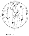
- FIG. 1 illustrates a satellite-based communication network 10.
- Network 10 is dispersed over the earth through the use of several above-the-earth communication nodes, such as orbiting satellites 12.
- satellites 12 occupy polar, low-earth orbits 14.
- the preferred embodiment of network 10 uses seven polar orbits, with each orbit holding eleven satellites 12. For clarity, FIG. 1 illustrates only a few of these satellites 12.
- Orbits 14 and satellites 12 are distributed around the earth. Each orbit 14 encircles the earth at an altitude of around 765 km. Due to these low-earth orbits 14, satellites 12 travel with respect to the earth at around 25,000 km/hr. Together, satellites 12 form a constellation in which satellites 12 remain relatively stationary with respect to one another, except for their orbits converging and crossing over each other in the polar regions. In particular, each satellite 12 resides a distance of around 4000 km from its neighboring satellites 12 in the same orbital plane 14, and electromagnetic signals require approximately 13.4 msec to travel this distance. This in-plane distance and corresponding signal propagation time remain relatively constant.
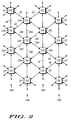
- FIG. 2 presents a static, two dimensional map of the relative orientation of satellites 12.
- satellites 12 in even orbital planes 14a reside at approximately the same latitudes on one side of the earth.
- satellites 12 reside at approximately the same latitudes on one side of the earth for all odd planes 14b.
- odd-plane satellites 12 are positioned out-of-phase with even-plane satellites 12.
- the latitudes of odd-plane satellites 12 are approximately half way between the latitudes for nearby even-plane satellites 12.
- a line-of-sight exists between each satellite 12 and fore and aft satellites 12 in the same plane 14, and fore and aft satellites 12 in adjacent planes.
- the preferred embodiment employs RF communications, preferably in the 20-30 GHz range, to establish communication links 16 between each satellite 12 and its neighbor satellites 12.
- RF communications preferably in the 20-30 GHz range
- up to six line-of-sight, bi-directional, RF communication links 16 are supported for each satellite 12.
- fore and aft links 16a and 16b exist between a satellite 12x and the preceding and following satellites 12a and 12b, respectively, orbiting in the same plane 14 (i.e. in-plane satellites).
- Fore-right and aft-right links 16c and 16d exist between satellite 12x and the preceding and following satellites 12c and 12d, respectively, orbiting in a right side adjacent plane 14 (i.e. cross-plane satellites).
- fore-left and aft-left links 16e and 16f exist between satellite 12x and the preceding and following satellites 12e and 12f, respectively, orbiting in a left side adjacent plane 14.
- Each satellite 12 illustrated in FIG. 2 supports a similar orientation of links 16.
- all of RF links 16a-16f for each satellite 12 utilize the same frequency spectrum, and all links 16a-16f transmit and receive communications over this spectrum.
- the distance between satellites 12 in adjacent orbits 14 varies with latitude.
- the greatest distance between cross-plane satellites 12 exists at the equator. This distance decreases as satellites 12 approach the polar regions.
- Electromagnetic signals require between 7 and 13 msec, depending on the latitude, to travel between nearby cross-plane satellites 12.
- FIGs. 1-2 and the above-presented discussion describe a preferred orbital geometry for network 10, those skilled in the art will appreciate that the communication nodes which each satellite 12 provides need not be positioned as described herein. For example, such nodes may be located on the surface of the earth or in orbits other than those described herein. Likewise, the precise number of nodes may vary from network to network.
- Satellites 12 communicate with devices on the ground through many central switching offices (CSOs) 18, of which FIG. 1 shows only one, a few ground control stations (GCSs) 20, of which FIG. 1 shows only one, and any number of radiocommunication subscriber units 22, of which one is shown in FIG. 1.
- Subscriber units 22 may be located anywhere on the face of the earth.
- CSOs 18 are preferably distributed over the surface of the earth in accordance with geo-political boundaries.
- GCSs 20 preferably reside in extreme northern or southern latitudes, where the convergence of orbits 14 causes a greater number of satellites 12 to come within direct line-of-sight view of a single point on the surface of the earth with respect to more equatorial latitudes.
- Around four GCSs 20 are used so that all satellites 12 in the constellation may at some point in their orbits 14 come within direct view of their assigned GCS 20.
- GCSs 20 preferably perform telemetry, tracking, and control (TT&C) functions for the constellation of satellites 12.
- CSOs 18 operate as communication nodes in network 10.
- Diverse terrestrial-based communications systems such as the worldwide public switched telecommunications network (not shown), may access network 10 through CSOs 18. Due to the configuration of the constellation of satellites 12, at least one of satellites 12 is within view of each point on the surface of the earth at all times. Accordingly, network 10 may establish a communication circuit through the constellation of satellites 12 between any two subscriber units 22, between any subscriber unit 22 and a CSO 18, or between any two CSOs 18.
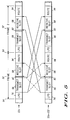
- FIG. 3 shows a block diagram of a communication node, for example a satellite 12, used by network 10 (see FIG. 1).
- Satellite 12 includes any number of transceivers.
- one transceiver 24 serves each link 16.
- transceivers 24a-24f correspond to links 16a-16f, respectively (see FIG. 2).
- satellite 12 includes an earth-link transceiver 26 and a subscriber-unit transceiver 28. Satellite 12 communicates with CSOs 18 and GCSs 20 (see FIG. 1) through transceiver 26, and with subscriber units 22 (see FIG. 1) through transceiver 28.
- Each of transceivers 24, 26, and 28 couple to corresponding antennas 30, 32, and 34, respectively.
- antennas 30, 32, and 34 at least antennas 30a-30f are preferably directional antennas which may be oriented for maximum signal strength in the line-of-sight direction corresponding to links 16a-16f (see FIG. 2), respectively.
- Each transceiver 24 may include various sub-components common in the art, as illustrated in connection with fore-left transceiver 24e.
- each transceiver 24 may include a receiver 36 and a transmitter 38.
- Each receiver 36 couples to an input buffer 40, into which input data is placed after the data are received at satellite 12 and demodulated.
- Each transmitter 38 couples to an output buffer 42, from which data are obtained for modulation and radiation or broadcasting away from satellite 12. Desirably, all data placed in buffers 40-42 during one frame are disposed of by the end of the next frame. Thus, input buffers 40 and output buffers 42 are held to a minimal configuration.
- receivers 36 and transmitters 38 for each transceiver 24 operate in the same frequency band. Moreover, receivers 36 operate at different times than transmitters 38. Thus, receivers 36 and transmitters 38 may advantageously share numerous components, such as oscillators, timing circuits, and the like (not shown) to simplify satellite design. Moreover, since receivers 36 are not required to receive data while transmitters 38 are operating, a minimal amount of isolation shielding is required. The simplified satellite design, reduction in shielding, and minimal data buffering lowers satellite weight, improves reliability, and reduces costs associated with satellites 12 within network 10 (see FIG. 1).
- transceivers 26 and 28 need not utilize the same frequency spectrum as transceivers 24.
- transceivers 26 and 28 operate at frequencies which are sufficiently removed from the spectrum of transceivers 24 so that only a minimal amount of isolation shielding is required.
- Processor 46 may be implemented using a single processor or multiple processors operated in a parallel architecture. Generally speaking, processor 46 coordinates and controls transceivers 24 so that satellite 12 receives data communications from links 16, appropriately distributes the received communications among output buffers 42, and transmits the communications back out into links 16. Data communications are also received from and transmitted to the surface of the earth via transceivers 26 and 28.
- Timer 44 is utilized to synchronize processor 46 and satellite 12 with timing constraints imposed by network 10 (see FIG. 1).
- the memory components include a duration table 48.
- Table 48 associates durations with latitudes in a one to one correspondence. Thus, by supplying a latitude to table 48 a duration may be obtained. In alternate embodiments, table 48 associates durations with time values, distances with latitudes, distances with time values, or the like. Regardless of the selected embodiment, by supplying a key which corresponds to a satellite's location, table 48 provides data that corresponds to the duration required for an electromagnetic signal to propagate from satellite 12 to a nearby satellite 12 along cross-plane links 16c-16f (see FIG. 2). These duration data are responsive to the distances between satellite 12 and nearby satellites 12 at the indicated latitudes.
- These data may directly represent the duration, or they may represent the distance which can be divided by the speed of signal propagation to produce the duration.
- the data used as a key may directly represent latitude or they may represent a point in time that corresponds to a particular point in the orbit of a satellite 12.
- the memory components also include other memory 50.
- Memory 50 includes data which serve as instructions to processor 46 and which, when executed by processor 46, cause satellite 12 to carry out procedures that are discussed below.
- Memory 50 also includes other variables, tables, and databases that are manipulated due to the operation of satellite 12.
- FIGs. 4 and 5 show timing diagrams that illustrate bi-directional communication in accordance with the present invention.
- FIG. 4 depicts a first embodiment of the present invention
- FIG. 5 depicts a second embodiment of the present invention.
- Each of FIGs. 4-5 depicts only a single link 16 (see FIGs. 1-2). Nevertheless, the timing illustrated therein applies to all links 16 within network 10 (see FIG. 1). In other words, all links 16 within network 10 operate substantially as depicted in FIGs. 4-5.
- two satellites 12 that are communicating with each other communicate using constant duration frames 52.
- the constant frame duration is maintained throughout network 10 to minimize the data buffering needed within satellites 12 and to simplify satellite design.
- the duration of frames 52 may, for example, be around 30 msec.
- Each frame begins at the same instant 54 for all satellites 12 within network 10.
- each frame 52 Approximately half of each frame 52 is dedicated to transmitting data into link 16, and a different half of each frame 52 is dedicated to receiving data from link 16.
- Each of satellites 12a and 12b begins transmitting data communications into link 16 at substantially the same instant and continues transmitting, during a transmit slot 56, for the same duration. Due to the communications' finite speed of propagation and the distance between satellites 12, the communications require a certain duration to propagate to the other node of the link 16. In accordance with the above-discussed orbital geometry, this duration remains constant at around 13.4 msec for a link 16 between in-plane satellites 12a-12b (see FIG. 2). This duration varies between 7 and 13 msec for a link 16 between cross-plane satellites 12c-12f (see FIG. 2), depending on the latitude of the satellites 12.
- Time slot 56 is configured so that transmission from each satellite 12 ceases before the signal from the opposing party to the link 16 arrives. After halting transmission, each of the nodes operate in a receive mode, and the other party's transmitted communication is received during a receive slot 58.
- data transmitted from satellite 12x during the beginning of a frame 52 are received at satellites 12a-12f during the end of the same frame 52, and data transmitted from satellites 12a-12f during the beginning of this same frame 52 are received at satellite 12x during the end of the same frame 52.
- data transmitted from satellites 12 during the beginning of a frame 52 are received at the opposing nodes during the end of either the same frame 52 or a subsequent frame 52.
- the quantity of intervening frames 52 between when a communication is sent from one node and received at another node depends on the distance between the nodes. Zero or more intervening frames are interposed when propagation delays warrant.
- the length of frame 52 may be reduced from that discussed above in connection with the FIG. 4 embodiment, for example to around 15 msec.
- the reduction in frame size reduces an overall end-to-end delay of a communication propagating through network 10 in exchange for channel capacity when satellites 12 are located certain discrete distances apart.
- FIG. 6 shows a flow chart of a Control procedure 60 performed by a single satellite 12.
- Procedure 60 causes satellite 12 to become synchronized to an external timing signal.
- TT&C may involve numerous diverse commands, such as orbit control commands, diagnostics commands, and programming commands, to name a few.
- Such TT&C commands may additionally include a synchronizing command.
- program control retrieves data from the synchronizing command and programs timer 44 (see FIG. 3) in response to synchronization data carried by the command, as shown in a task 64.
- satellites 12 orbit the earth once approximately every 100 minutes. Thus, they are over a GCS 20 once every 100 minutes and may synchronize their internal time to the system time for network 10 every 100 minutes. With every satellite 12 performing substantially the same procedure, the internal timers 44 of all satellites 12 recognize a given point in time at substantially the same instant. In the preferred embodiment, timers 44 for all of satellites 12 remain synchronized to within 50 microseconds of one another.
- procedure 60 may engage in other TT&C activities not related to the present invention. Due to the operation of procedure 60, all satellites 12 within network 10 recognize instant 54 (see FIGs. 4-5), denoting the beginning of a frame, at substantially the same actual point in time for all frames 52.
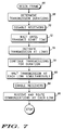
- FIG. 7 shows a flow chart of a Begin Frame procedure 66 performed by a single satellite 12.
- Procedure 66 causes satellite 12 to communicate in the fashion illustrated in FIGs. 4-5.
- Procedure 66 may be initiated in response to the beginning of each frame 52 (see FIGs. 4-5).
- Procedure 66 may, for example, be initiated by an interrupt supplied by timer 44 (see FIG. 3).
- Procedure 66 continuously repeats as a continuous stream of frames 52 are processed at satellite 12.
- each satellite 12 begins procedure 66 at substantially the same instant in time since all satellites 12 are synchronized, as discussed above.
- Procedure 66 performs a task 68 to determine the durations for transmit slots 56 (see FIGs. 4-5). As discussed above, each transmit slot 56 lasts for a duration slightly less than the time it takes for a communication to propagate through a link 16. Since each satellite 12 supports a plurality of links 16, a plurality of durations are determined in task 68. In plane links 16a and 16b (see FIG. 2) have a substantially constant propagation delay because the satellites 12 terminating these links 16 remain a substantially constant distance apart. Thus, the corresponding durations may be obtained by retrieving a predetermined constant, for example 13.4 msec, from memory 50 (see FIG. 3).
- a predetermined constant for example 13.4 msec
- the propagation delay for links 16 to satellites 12c-12f (see FIG. 2) in other orbits 14 varies as these other orbits 14 converge near the polar regions (see FIG. 1).
- the corresponding durations for these cross-plane links 16 may be obtained by a table look-up operation using duration table 48 (see FIG. 3). The resulting duration will represent a period of time sightly less than the distance between satellites 12 divided by the speed of propagation for a signal, which is approximately the speed of light in the preferred embodiment.
- a task 70 disables the receivers 36 of the transceivers 24 (see FIG. 3) serving the corresponding links 16a-16f (see FIG. 2). All receivers 36 of transceivers 24 are disabled in preparation for an upcoming transmit slot 56 (see FIGs. 4-5), when transmitters 38 (see FIG. 3) will be active.
- a task 72 waits, without transmitting data, until the beginning of the upcoming transmit slot 56.
- Task 72 is performed independently for each link 16 of satellite 12.
- different wait times may be used in connection with different ones of links 16a-16f.
- the wait times can be determined from the duration values obtained above in task 68.
- the beginning of transmit slot 56 is delayed within the half of frame 52 dedicated to transmitting data so that the first data transmitted arrives at the opposite end of a link 16 at the beginning of the receive portion of frame 52.
- This wait corresponds to a link path delay (LPD) 74 shown in FIGs. 4-5.
- LPD link path delay
- the duration of LPD 74 is determined by subtracting the transmission duration from the duration of the transmission portion of frame 52.
- a task 76 initiates the transmission of data into the link 16.
- Task 76 denotes the start of transmit slot 56 (see FIGs. 4-5).
- a task 78 continues transmissions for the corresponding links 16 through the duration of transmit slot 56, and a task 80 halts transmission into each link at the end of time slots 56 for the links 16. Transmission into each link 16a-16f ceases at substantially the same instant for all satellites 12. This instant should occur just prior to the beginning of receive slot 58.
- a transmit/receive time buffer 82 illustrated in FIGs. 4-5 is provided to compensate for any error in synchronization between the various satellites 12 of network 10.
- a task 84 enables receivers 36 of transceivers 24 for the upcoming receive slot 58.
- Receivers 36 are operational by the end of time buffer 82 (see FIGs. 4-5), and a task 86 is performed for each link 16 supported by satellite 12 to receive any data directed thereto through the links 16.
- Task 86 receives data from the various links 16 and routes this data to appropriate output buffers 42 (see FIG. 3).
- FIG. 8 shows a block diagram of data communicated between nodes in network 10. These data may desirably be formatted into packets 88, with each packet 88 including a header portion 90 and a payload portion 92. Header 90 includes routing data and any other network control data which network 10 may deem useful in providing communication services. Payload portion 92 includes the data being communicated by network 10.
- processor 46 examines headers 92 to determine where to route the corresponding packets 88. After making this determination, the packets 88 are placed in the output buffers 42 (see FIG. 3) associated with those links 16 that get the packets 88 to their intended destinations. Alternatively, some of headers 92 may indicate that their corresponding packets 88 should be routed through earth-link or subscriber-unit transceivers 26 or 28, respectively, (see FIG. 3) for delivery.
- Task 86 continues throughout receive slot 58 (see FIGs. 4-5). As discussed above, data were transmitted only during transmit slot 56, and slot 56 is shorter than the half of frame 52 that is dedicated to transmitting data. Consequently, receive slot 58 ends prior to the end of the half of frame 52 dedicated to receiving data and prior to the end of frame 52. A route time slot 94 remains within frame 52 after receive slot 58. Route time slot 94 may be used by processor 46 (see FIG. 3) to continue the routing of all data received during receive slot 58 (see FIGs. 4-5) in preparation for the next transmit slot 56 of the next frame 52.
- program control stops or performs other tasks not related to the present invention. However, when the next frame 52 begins, process 66 repeats.
- the present invention provides an improved bi-directional communication system and method.
- the system and method of the present invention avoids the isolation problems associated with full duplex operation because receivers are not required to operate at the same time that transmitters are operating.
- the system and method of the present invention avoids the control and delay problems associated with conventional half duplex operation. Control is maintained because all satellites 12 operate synchronously in accordance with an externally supplied system time. Signal delay is minimized because both parties to a link transmit simultaneously. Thus, the links simultaneously support communications traveling in opposite directions.
- the system and method of the present invention simplify satellite design. Little shielding is required for isolation purposes because transmitters and receivers do not operate simultaneously. Relatively little data buffering is required because constant duration frames are utilized and all data are routed through a satellite within a single frame. Moreover, many circuit components may be shared between the various transmitters and receivers utilized to support a plurality of communication links. The simplicity in satellite design reduces weight and power consumption and improves reliability, all of which lead to reduced satellite costs.
Landscapes
- Engineering & Computer Science (AREA)
- Physics & Mathematics (AREA)
- Astronomy & Astrophysics (AREA)
- Aviation & Aerospace Engineering (AREA)
- General Physics & Mathematics (AREA)
- Computer Networks & Wireless Communication (AREA)
- Signal Processing (AREA)
- Radio Relay Systems (AREA)
- Catching Or Destruction (AREA)
- Mobile Radio Communication Systems (AREA)
Abstract
Description
- The present invention relates generally to communication systems. More specifically, the present invention relates to such systems which utilize time division multiple access (TDMA) techniques for engaging in bi-directional communications.
- Bi-directional communications may use communication links or channels through which signals are delivered. Such signals may be sent over wires, optical fibers, or be modulated for delivery through space in the form of RF communications or for delivery through water or air in the form of acoustic communications. Bi-directional communications address interference problems. For example, when two nodes exchange communications, each node must be able to distinguish its own transmitted signals from the signals transmitted by the other node.
- Conventional bi-directional communications contemplate full duplex or half duplex operation. Full duplex operation uses two, oppositely directed, simplex or unidirectional links which operate simultaneously. No interference results because the two links operate independently from one another. For example, one link may use an entirely separate set of wires or fibers from the other link, or one link may use an entirely separate frequency band or set of frequencies from the other link. With full duplex operation, each party transmits over one link while simultaneously receiving over the other link. Half duplex operation utilizes only a single link. Communication may travel in either direction over this single link so long as it travels in only one direction at a time. Interference is avoided because nodes which utilize the link refrain from transmitting and receiving at the same time.
- Full duplex operation is often preferred over half duplex operation. Assuming that a single half duplex link and the two simplex links used by a full duplex operation have the same capacity, a greater amount of data may be communicated using full duplex operation. Moreover, with full duplex operation, link management and timing concerns become trivial. On the other hand, with half duplex operation the communication system must devise schemes to determine when to allow different nodes to transmit over the link.
- When RF communication links are established through space, and particularly outer space, the desirability of full duplex operation fades. For example, even though two simplex links may utilize different portions of the spectrum, transmission circuits adapted to operate in one portion of the spectrum must be isolated from receive circuits that are adapted to operate in another portion of the spectrum. This isolation is often accomplished at the cost of massive shielding and increased circuit complexity. When the node operating one end of the link is a satellite, the weight of shielding and increased circuit complexity can make satellite costs excessive.
- Moreover, when a node operates more than one bi-directional link, the total number of independent spectrum bands needed to carry non-interfering communications increases. Thus, a given amount of spectrum may be divided into a greater number of closely spaced independent frequency bands. As the number of frequency bands increases, so do the isolation problems discussed above.
- While conventional half duplex operation does not suffer from the isolation problems associated with full duplex operation, it has its own problems. The half duplex requirement that only one node use the link at a time results in an inefficient use of the link. Nodes may be required to wait between transmitting one communication and receiving another. The wait is imposed by the time it takes the communications to travel between nodes, and is often greater than the duration of a communication signal's round trip between the nodes. For example, a first node that has just completed a first transmission into a link must wait for a second node to finish receiving the first transmission, for the second node to begin a second transmission, and for the second transmission to reach the first node, before receiving data from the link. When nodes are located hundreds or thousands of miles apart, this wait can impose significant delays on communication. Moreover, as more nodes engage in half duplex communication among each other, the amount of data that can be delivered between any two nodes decreases.
- Accordingly, it is an advantage of the present invention that an improved bi-directional communication system and method are provided.
- Another advantage of the present invention is that a bi-directional communication system and method are provided which are free from the isolation problems associated with full duplex operation.
- Another advantage of the present invention is that a bi-directional communication system and method are provided which reduces the inefficiencies of half duplex operation.
- Another advantage of the present invention is that a bi-directional communication system and method are provided which can be implemented using simple circuit designs and which is suitable for implementation in satellites.
- The above and other advantages of the present invention are carried out in one form by a method of communicating data between first and second nodes through a communication channel. The method calls for transmitting, beginning at a first point in time, first data into the channel from the first node. Beginning at substantially the first point in time, second data is transmitted into the channel from a second node. The first data is received from the channel, starting at a second point in time, at the second node. The second data is received from the channel, starting at substantially the second point in time, at the first node.
- A more complete understanding of the present invention may be derived by referring to the detailed description and claims when considered in connection with the Figures, wherein like reference numbers refer to similar items throughout the Figures, and:
- FIG. 1 shows a layout diagram of an environment within which one embodiment of the present invention is practiced;
- FIG. 2 shows a layout diagram of communication links between nodes of a communication network;
- FIG. 3 shows a block diagram of a node of the communication network;
- FIG. 4 shows a timing diagram depicting bi-directional communication in accordance with a first embodiment of the present invention;
- FIG. 5 shows a timing diagram depicting bi-directional communication in accordance with a second embodiment of the present invention;
- FIG. 6 shows a flow chart of a Control procedure performed by nodes of the communication network;
- FIG. 7 shows a flow chart of a Begin Frame procedure performed by nodes of the communication network; and
- FIG. 8 shows a block diagram of data communicated between nodes of the communication network.
- FIG. 1 illustrates a satellite-based
communication network 10.Network 10 is dispersed over the earth through the use of several above-the-earth communication nodes, such as orbitingsatellites 12. In the preferred embodiment,satellites 12 occupy polar, low-earth orbits 14. In particular, the preferred embodiment ofnetwork 10 uses seven polar orbits, with each orbit holding elevensatellites 12. For clarity, FIG. 1 illustrates only a few of thesesatellites 12. -
Orbits 14 andsatellites 12 are distributed around the earth. Eachorbit 14 encircles the earth at an altitude of around 765 km. Due to these low-earth orbits 14,satellites 12 travel with respect to the earth at around 25,000 km/hr. Together,satellites 12 form a constellation in whichsatellites 12 remain relatively stationary with respect to one another, except for their orbits converging and crossing over each other in the polar regions. In particular, eachsatellite 12 resides a distance of around 4000 km from its neighboringsatellites 12 in the sameorbital plane 14, and electromagnetic signals require approximately 13.4 msec to travel this distance. This in-plane distance and corresponding signal propagation time remain relatively constant. - FIG. 2 presents a static, two dimensional map of the relative orientation of
satellites 12. With reference to FIGs. 1-2, at any giveninstant satellites 12 in evenorbital planes 14a reside at approximately the same latitudes on one side of the earth. Likewise,satellites 12 reside at approximately the same latitudes on one side of the earth for allodd planes 14b. However, odd-plane satellites 12 are positioned out-of-phase with even-plane satellites 12. At any given instant, the latitudes of odd-plane satellites 12 are approximately half way between the latitudes for nearby even-plane satellites 12. - A line-of-sight exists between each
satellite 12 and fore andaft satellites 12 in thesame plane 14, and fore andaft satellites 12 in adjacent planes. The preferred embodiment employs RF communications, preferably in the 20-30 GHz range, to establishcommunication links 16 between eachsatellite 12 and itsneighbor satellites 12. With reference to FIG. 2, up to six line-of-sight, bi-directional, RF communication links 16 are supported for eachsatellite 12. As shown in FIG. 2, fore andaft links satellite 12x and the preceding and followingsatellites right links satellite 12x and the preceding and followingsatellites links satellite 12x and the preceding and followingsatellites adjacent plane 14. Eachsatellite 12 illustrated in FIG. 2 supports a similar orientation oflinks 16. In the preferred embodiment, all ofRF links 16a-16f for eachsatellite 12 utilize the same frequency spectrum, and alllinks 16a-16f transmit and receive communications over this spectrum. - With reference back to FIG. 1, the distance between
satellites 12 inadjacent orbits 14 varies with latitude. The greatest distance betweencross-plane satellites 12 exists at the equator. This distance decreases assatellites 12 approach the polar regions. Electromagnetic signals require between 7 and 13 msec, depending on the latitude, to travel between nearbycross-plane satellites 12. - While FIGs. 1-2 and the above-presented discussion describe a preferred orbital geometry for
network 10, those skilled in the art will appreciate that the communication nodes which eachsatellite 12 provides need not be positioned as described herein. For example, such nodes may be located on the surface of the earth or in orbits other than those described herein. Likewise, the precise number of nodes may vary from network to network. -
Satellites 12 communicate with devices on the ground through many central switching offices (CSOs) 18, of which FIG. 1 shows only one, a few ground control stations (GCSs) 20, of which FIG. 1 shows only one, and any number ofradiocommunication subscriber units 22, of which one is shown in FIG. 1.Subscriber units 22 may be located anywhere on the face of the earth.CSOs 18 are preferably distributed over the surface of the earth in accordance with geo-political boundaries. GCSs 20 preferably reside in extreme northern or southern latitudes, where the convergence oforbits 14 causes a greater number ofsatellites 12 to come within direct line-of-sight view of a single point on the surface of the earth with respect to more equatorial latitudes. Preferably, around four GCSs 20 are used so that allsatellites 12 in the constellation may at some point in theirorbits 14 come within direct view of their assigned GCS 20. - Nothing prevents
CSOs 18 and GCSs 20 from being located together on the ground. However,CSOs 18 serve a different function from that of GCSs 20. GCSs 20 preferably perform telemetry, tracking, and control (TT&C) functions for the constellation ofsatellites 12.
Preferably,CSOs 18 operate as communication nodes innetwork 10. Diverse terrestrial-based communications systems, such as the worldwide public switched telecommunications network (not shown), may accessnetwork 10 throughCSOs 18. Due to the configuration of the constellation ofsatellites 12, at least one ofsatellites 12 is within view of each point on the surface of the earth at all times. Accordingly,network 10 may establish a communication circuit through the constellation ofsatellites 12 between any twosubscriber units 22, between anysubscriber unit 22 and aCSO 18, or between any twoCSOs 18. - FIG. 3 shows a block diagram of a communication node, for example a
satellite 12, used by network 10 (see FIG. 1).Satellite 12 includes any number of transceivers. For example, one transceiver 24 serves eachlink 16. Thus,transceivers 24a-24f correspond tolinks 16a-16f, respectively (see FIG. 2). In addition,satellite 12 includes an earth-link transceiver 26 and a subscriber-unit transceiver 28.Satellite 12 communicates withCSOs 18 and GCSs 20 (see FIG. 1) throughtransceiver 26, and with subscriber units 22 (see FIG. 1) throughtransceiver 28. - Each of
transceivers corresponding antennas antennas least antennas 30a-30f are preferably directional antennas which may be oriented for maximum signal strength in the line-of-sight direction corresponding tolinks 16a-16f (see FIG. 2), respectively. - Each transceiver 24 may include various sub-components common in the art, as illustrated in connection with fore-left
transceiver 24e. For example, each transceiver 24 may include areceiver 36 and atransmitter 38. Eachreceiver 36 couples to aninput buffer 40, into which input data is placed after the data are received atsatellite 12 and demodulated. Eachtransmitter 38 couples to anoutput buffer 42, from which data are obtained for modulation and radiation or broadcasting away fromsatellite 12. Desirably, all data placed in buffers 40-42 during one frame are disposed of by the end of the next frame. Thus, input buffers 40 andoutput buffers 42 are held to a minimal configuration. - In accordance with the preferred embodiment of the present invention,
receivers 36 andtransmitters 38 for each transceiver 24 operate in the same frequency band. Moreover,receivers 36 operate at different times thantransmitters 38. Thus,receivers 36 andtransmitters 38 may advantageously share numerous components, such as oscillators, timing circuits, and the like (not shown) to simplify satellite design. Moreover, sincereceivers 36 are not required to receive data whiletransmitters 38 are operating, a minimal amount of isolation shielding is required. The simplified satellite design, reduction in shielding, and minimal data buffering lowers satellite weight, improves reliability, and reduces costs associated withsatellites 12 within network 10 (see FIG. 1). - In the preferred embodiment of the present invention,
transceivers transceivers -
Transceivers timer 44, couple to aprocessor 46.Processor 46 may be implemented using a single processor or multiple processors operated in a parallel architecture. Generally speaking,processor 46 coordinates and controls transceivers 24 so thatsatellite 12 receives data communications fromlinks 16, appropriately distributes the received communications amongoutput buffers 42, and transmits the communications back out intolinks 16. Data communications are also received from and transmitted to the surface of the earth viatransceivers Timer 44 is utilized to synchronizeprocessor 46 andsatellite 12 with timing constraints imposed by network 10 (see FIG. 1). - The memory components include a duration table 48. Table 48 associates durations with latitudes in a one to one correspondence. Thus, by supplying a latitude to table 48 a duration may be obtained. In alternate embodiments, table 48 associates durations with time values, distances with latitudes, distances with time values, or the like. Regardless of the selected embodiment, by supplying a key which corresponds to a satellite's location, table 48 provides data that corresponds to the duration required for an electromagnetic signal to propagate from
satellite 12 to anearby satellite 12 alongcross-plane links 16c-16f (see FIG. 2). These duration data are responsive to the distances betweensatellite 12 andnearby satellites 12 at the indicated latitudes. These data may directly represent the duration, or they may represent the distance which can be divided by the speed of signal propagation to produce the duration. The data used as a key may directly represent latitude or they may represent a point in time that corresponds to a particular point in the orbit of asatellite 12. - The memory components also include
other memory 50.Memory 50 includes data which serve as instructions toprocessor 46 and which, when executed byprocessor 46,cause satellite 12 to carry out procedures that are discussed below.Memory 50 also includes other variables, tables, and databases that are manipulated due to the operation ofsatellite 12. - FIGs. 4 and 5 show timing diagrams that illustrate bi-directional communication in accordance with the present invention. FIG. 4 depicts a first embodiment of the present invention and FIG. 5 depicts a second embodiment of the present invention. Each of FIGs. 4-5 depicts only a single link 16 (see FIGs. 1-2). Nevertheless, the timing illustrated therein applies to all
links 16 within network 10 (see FIG. 1). In other words, alllinks 16 withinnetwork 10 operate substantially as depicted in FIGs. 4-5. - With reference to FIG. 4, two
satellites 12 that are communicating with each other, such assatellite 12x and one ofsatellites 12a-12f (see FIG. 2), communicate using constant duration frames 52. The constant frame duration is maintained throughoutnetwork 10 to minimize the data buffering needed withinsatellites 12 and to simplify satellite design. The duration offrames 52 may, for example, be around 30 msec. Each frame begins at thesame instant 54 for allsatellites 12 withinnetwork 10. - Approximately half of each
frame 52 is dedicated to transmitting data intolink 16, and a different half of eachframe 52 is dedicated to receiving data fromlink 16. Each ofsatellites link 16 at substantially the same instant and continues transmitting, during a transmitslot 56, for the same duration. Due to the communications' finite speed of propagation and the distance betweensatellites 12, the communications require a certain duration to propagate to the other node of thelink 16. In accordance with the above-discussed orbital geometry, this duration remains constant at around 13.4 msec for alink 16 between in-plane satellites 12a-12b (see FIG. 2). This duration varies between 7 and 13 msec for alink 16 betweencross-plane satellites 12c-12f (see FIG. 2), depending on the latitude of thesatellites 12. -
Time slot 56 is configured so that transmission from eachsatellite 12 ceases before the signal from the opposing party to thelink 16 arrives. After halting transmission, each of the nodes operate in a receive mode, and the other party's transmitted communication is received during a receiveslot 58. - In the embodiment of the present invention depicted in FIG. 4, data transmitted from
satellite 12x during the beginning of aframe 52 are received atsatellites 12a-12f during the end of thesame frame 52, and data transmitted fromsatellites 12a-12f during the beginning of thissame frame 52 are received atsatellite 12x during the end of thesame frame 52. - In accordance with the FIG. 5 embodiment, data transmitted from
satellites 12 during the beginning of aframe 52 are received at the opposing nodes during the end of either thesame frame 52 or asubsequent frame 52. The quantity of interveningframes 52 between when a communication is sent from one node and received at another node depends on the distance between the nodes. Zero or more intervening frames are interposed when propagation delays warrant. With the second embodiment, the length offrame 52 may be reduced from that discussed above in connection with the FIG. 4 embodiment, for example to around 15 msec. The reduction in frame size reduces an overall end-to-end delay of a communication propagating throughnetwork 10 in exchange for channel capacity whensatellites 12 are located certain discrete distances apart. - FIG. 6 shows a flow chart of a
Control procedure 60 performed by asingle satellite 12.Procedure 60 causessatellite 12 to become synchronized to an external timing signal. Those skilled in the art will appreciate that, whileprocedure 60 is described for asingle satellite 12, each ofsatellites 12 desirably performs substantially the same procedure. Generally speaking,Control procedure 60 is invoked when a TT&C command is received from a GCS 20 (see FIG. 1). TT&C may involve numerous diverse commands, such as orbit control commands, diagnostics commands, and programming commands, to name a few. - Such TT&C commands may additionally include a synchronizing command. When the synchronizing command is detected, as indicated at a
query task 62, program control retrieves data from the synchronizing command and programs timer 44 (see FIG. 3) in response to synchronization data carried by the command, as shown in atask 64. In the preferred embodiment,satellites 12 orbit the earth once approximately every 100 minutes. Thus, they are over a GCS 20 once every 100 minutes and may synchronize their internal time to the system time fornetwork 10 every 100 minutes. With everysatellite 12 performing substantially the same procedure, theinternal timers 44 of allsatellites 12 recognize a given point in time at substantially the same instant. In the preferred embodiment,timers 44 for all ofsatellites 12 remain synchronized to within 50 microseconds of one another. After synchronization,procedure 60 may engage in other TT&C activities not related to the present invention. Due to the operation ofprocedure 60, allsatellites 12 withinnetwork 10 recognize instant 54 (see FIGs. 4-5), denoting the beginning of a frame, at substantially the same actual point in time for all frames 52. - FIG. 7 shows a flow chart of a
Begin Frame procedure 66 performed by asingle satellite 12.Procedure 66 causessatellite 12 to communicate in the fashion illustrated in FIGs. 4-5. Those skilled in the art will appreciate that, whileprocedure 66 is described for asingle satellite 12, each ofsatellites 12 desirably performs substantially the same procedure.Procedure 66 may be initiated in response to the beginning of each frame 52 (see FIGs. 4-5).Procedure 66 may, for example, be initiated by an interrupt supplied by timer 44 (see FIG. 3).Procedure 66 continuously repeats as a continuous stream offrames 52 are processed atsatellite 12. Moreover eachsatellite 12 beginsprocedure 66 at substantially the same instant in time since allsatellites 12 are synchronized, as discussed above. -
Procedure 66 performs atask 68 to determine the durations for transmit slots 56 (see FIGs. 4-5). As discussed above, each transmitslot 56 lasts for a duration slightly less than the time it takes for a communication to propagate through alink 16. Since eachsatellite 12 supports a plurality oflinks 16, a plurality of durations are determined intask 68. Inplane links satellites 12 terminating theselinks 16 remain a substantially constant distance apart. Thus, the corresponding durations may be obtained by retrieving a predetermined constant, for example 13.4 msec, from memory 50 (see FIG. 3). - On the other hand, the propagation delay for
links 16 tosatellites 12c-12f (see FIG. 2) inother orbits 14 varies as theseother orbits 14 converge near the polar regions (see FIG. 1). Thus, the corresponding durations for thesecross-plane links 16 may be obtained by a table look-up operation using duration table 48 (see FIG. 3). The resulting duration will represent a period of time sightly less than the distance betweensatellites 12 divided by the speed of propagation for a signal, which is approximately the speed of light in the preferred embodiment. - After
task 68, atask 70 disables thereceivers 36 of the transceivers 24 (see FIG. 3) serving the correspondinglinks 16a-16f (see FIG. 2). Allreceivers 36 of transceivers 24 are disabled in preparation for an upcoming transmit slot 56 (see FIGs. 4-5), when transmitters 38 (see FIG. 3) will be active. - After
task 70, atask 72 waits, without transmitting data, until the beginning of the upcoming transmitslot 56.Task 72 is performed independently for eachlink 16 ofsatellite 12. Thus, different wait times may be used in connection with different ones oflinks 16a-16f. The wait times can be determined from the duration values obtained above intask 68. In the preferred embodiment, the beginning of transmitslot 56 is delayed within the half offrame 52 dedicated to transmitting data so that the first data transmitted arrives at the opposite end of alink 16 at the beginning of the receive portion offrame 52. This wait corresponds to a link path delay (LPD) 74 shown in FIGs. 4-5. The duration ofLPD 74 is determined by subtracting the transmission duration from the duration of the transmission portion offrame 52. - After
task 72, for each link 16 atask 76 initiates the transmission of data into thelink 16.Task 76 denotes the start of transmit slot 56 (see FIGs. 4-5). Aftertask 76, atask 78 continues transmissions for the correspondinglinks 16 through the duration of transmitslot 56, and atask 80 halts transmission into each link at the end oftime slots 56 for thelinks 16. Transmission into eachlink 16a-16f ceases at substantially the same instant for allsatellites 12. This instant should occur just prior to the beginning of receiveslot 58. A transmit/receivetime buffer 82 illustrated in FIGs. 4-5 is provided to compensate for any error in synchronization between thevarious satellites 12 ofnetwork 10. - After
task 80 halts transmissions, atask 84 enablesreceivers 36 of transceivers 24 for the upcoming receiveslot 58.Receivers 36 are operational by the end of time buffer 82 (see FIGs. 4-5), and atask 86 is performed for eachlink 16 supported bysatellite 12 to receive any data directed thereto through thelinks 16.Task 86 receives data from thevarious links 16 and routes this data to appropriate output buffers 42 (see FIG. 3). - FIG. 8 shows a block diagram of data communicated between nodes in
network 10. These data may desirably be formatted intopackets 88, with eachpacket 88 including aheader portion 90 and apayload portion 92.Header 90 includes routing data and any other network control data whichnetwork 10 may deem useful in providing communication services.Payload portion 92 includes the data being communicated bynetwork 10. - Referring back to FIG. 7, during
task 86processor 46 examinesheaders 92 to determine where to route the correspondingpackets 88. After making this determination, thepackets 88 are placed in the output buffers 42 (see FIG. 3) associated with thoselinks 16 that get thepackets 88 to their intended destinations. Alternatively, some ofheaders 92 may indicate that theircorresponding packets 88 should be routed through earth-link or subscriber-unit transceivers -
Task 86 continues throughout receive slot 58 (see FIGs. 4-5). As discussed above, data were transmitted only during transmitslot 56, andslot 56 is shorter than the half offrame 52 that is dedicated to transmitting data. Consequently, receiveslot 58 ends prior to the end of the half offrame 52 dedicated to receiving data and prior to the end offrame 52. Aroute time slot 94 remains withinframe 52 after receiveslot 58.Route time slot 94 may be used by processor 46 (see FIG. 3) to continue the routing of all data received during receive slot 58 (see FIGs. 4-5) in preparation for the next transmitslot 56 of thenext frame 52. - After completion of
task 86, program control stops or performs other tasks not related to the present invention. However, when thenext frame 52 begins,process 66 repeats. - In summary, the present invention provides an improved bi-directional communication system and method. The system and method of the present invention avoids the isolation problems associated with full duplex operation because receivers are not required to operate at the same time that transmitters are operating. Moreover, the system and method of the present invention avoids the control and delay problems associated with conventional half duplex operation. Control is maintained because all
satellites 12 operate synchronously in accordance with an externally supplied system time. Signal delay is minimized because both parties to a link transmit simultaneously. Thus, the links simultaneously support communications traveling in opposite directions. - Furthermore, the system and method of the present invention simplify satellite design. Little shielding is required for isolation purposes because transmitters and receivers do not operate simultaneously. Relatively little data buffering is required because constant duration frames are utilized and all data are routed through a satellite within a single frame. Moreover, many circuit components may be shared between the various transmitters and receivers utilized to support a plurality of communication links. The simplicity in satellite design reduces weight and power consumption and improves reliability, all of which lead to reduced satellite costs.
- The present invention has been described above with reference to preferred embodiments. However, those skilled in the art will recognize that changes and modifications may be made in these preferred embodiments without departing from the scope of the present invention. For example, those skilled in the art will appreciate that the orbital geometry, timing, and distance values discussed herein are presented as examples only, and that the teaching of the present invention applies to network nodes which may or may not move, which may have a different geometry, and which may be characterized with different timing and distance values. These and other changes and modifications which are obvious to those skilled in the art are intended to be included within the scope of the present invention.
Claims (10)
- A method of communicating data wherein said data are communicated between first and second nodes (12) through a communication channel (16), said method comprising the steps of:a) transmitting (76), beginning at a first point in time, first data into said channel (16) from said first node;b) transmitting (72-76), beginning at substantially said first point in time, second data into said channel from said second node;c) receiving (86), beginning at a second point in time which occurs after said first point in time, said first data from said channel at said second node; andd) receiving (86), beginning at substantially said second point in time, said second data from said channel at said first node.
- A method as claimed in Claim 1 additionally comprising the steps of:
halting transmission of said first data from said first node prior to said second point in time; and
halting transmission of said second data from said second node prior to said second point in time (82). - A method as claimed in Claim 1 wherein said first and second nodes have first and second timers (44), respectively, and said method additionally comprises the step of synchronizing said first and second timers so that both timers indicate the occurrence of said first and second points in time (54) at substantially the same instant.
- A method as claimed in Claim 1 wherein said steps (a) through (d) define a single frame (52), and said method additionally comprises the steps of:
repeating said steps (a) through (d) to communicate data for a plurality of frames; and
configuring said steps (a) through (d) in each frame so that said frames (52) exhibit a substantially constant duration. - A method of exchanging communications through a communication channel (16) between first and second nodes (12), said communications propagating through said channel at a propagation speed, and said method comprising the steps of:
determining a transmission duration (68), said duration being less than a period of time equal to the distance between said first and second nodes divided by said propagation speed;
transmitting (76), from each of said first and second nodes, a communication into said channel, said communications being transmitted from said first and second nodes substantially simultaneously and said communications being transmitted from said first and second nodes for said transmission duration (78); and
receiving (86), at each of said first and second nodes, a communication from said channel, said receiving step occurring while said transmitting step is not being performed. - A method as claimed in Claim 5 wherein said transmitting step transmits first communications from said first and second nodes (12), and said method additionally comprises the steps of:
transmitting, after said receiving step, second communications into said channel from said first and second nodes, said second communications being transmitted from said first and second nodes substantially simultaneously; and
receiving, at said first and second nodes after said second communications transmitting step, said first communications from said channel, said first communications receiving step occurring while said transmitting step is not being performed. - A method of operating a node of a communications network (10) of spaced apart nodes (12) arranged in a predetermined orientation, said method comprising the steps of:
synchronizing a timer portion (44) of said node to an external timing signal;
transmitting a plurality of communications over a common frequency band to a corresponding plurality of said network nodes, said transmitting step being initiated in response to said timer;
receiving a plurality of communications over said frequency band from said corresponding plurality of network nodes, said receiving step being initiated in response to said timer; and
avoiding performance of said transmitting and receiving steps at the same time. - A method as claimed in Claim 7 additionally comprising the steps of:
determining durations (68) for which to perform said transmitting step to said plurality of network nodes, said durations (68) being responsive to distances between said one node and said plurality of said network nodes; and
timing said transmitting step (72) so that each of said communications continues for a corresponding one of said durations and so that said plurality of communications halt substantially simultaneously (80). - A node (12) for relaying communications within a network of spaced apart nodes (10) arranged in a predetermined orientation, said node comprising:
a timer (44);
means for synchronizing said timer to an external signal (26);
a plurality of transmitters (38), each transmitter being responsive to said timer, for simultaneously transmitting a plurality of communications over a common frequency band to a corresponding plurality of said network nodes;
a plurality of receivers (36), each receiver being responsive to said timer, for simultaneously receiving a plurality of communications over said frequency band from said corresponding plurality of network nodes; and
means, coupled to said transmitters and receivers (46), for avoiding simultaneous operation of one of said receivers with one of said transmitters. - A node (12) as claimed in Claim 9 additionally comprising:
means for determining durations (46) for which to operate said plurality of transmitters, said durations being responsive to distances between said node and said plurality of said network nodes; and
means, responsive to said duration determining means (48), for timing operation of said transmitters so that each of said plurality of communications continues for a corresponding one of said durations and so that said plurality of transmitters cease operations substantially simultaneously.
Applications Claiming Priority (2)
| Application Number | Priority Date | Filing Date | Title |
|---|---|---|---|
| US07/889,001 US5363368A (en) | 1992-05-26 | 1992-05-26 | Simultaneous TDMA communication system |
| US889001 | 1992-05-26 |
Publications (2)
| Publication Number | Publication Date |
|---|---|
| EP0571740A1 true EP0571740A1 (en) | 1993-12-01 |
| EP0571740B1 EP0571740B1 (en) | 2001-12-19 |
Family
ID=25394334
Family Applications (1)
| Application Number | Title | Priority Date | Filing Date |
|---|---|---|---|
| EP93105128A Expired - Lifetime EP0571740B1 (en) | 1992-05-26 | 1993-03-29 | TDMA communications between satellites, with distance dependant transmission duration |
Country Status (7)
| Country | Link |
|---|---|
| US (1) | US5363368A (en) |
| EP (1) | EP0571740B1 (en) |
| JP (1) | JPH0637687A (en) |
| AT (1) | ATE211335T1 (en) |
| CA (1) | CA2092743A1 (en) |
| DE (1) | DE69331361T2 (en) |
| RU (1) | RU2136109C1 (en) |
Cited By (10)
| Publication number | Priority date | Publication date | Assignee | Title |
|---|---|---|---|---|
| EP0767547A2 (en) * | 1995-10-03 | 1997-04-09 | Trw Inc. | Multiple altitude satellite relay system and method |
| EP0845876A2 (en) * | 1996-11-27 | 1998-06-03 | Trw Inc. | Multiple altitude satellite relay system and method |
| EP0849890A2 (en) * | 1996-12-19 | 1998-06-24 | Globalstar L.P. | Satellite low orbital communication system with connection through earth gateway |
| EP1033828A2 (en) * | 1999-03-04 | 2000-09-06 | TRW Inc. | Supplemental satellite function enhancement technique |
| EP1033829A2 (en) * | 1999-03-04 | 2000-09-06 | TRW Inc. | Supplemental satellite communication enhancement technique |
| EP1137196A1 (en) * | 2000-03-24 | 2001-09-26 | Trw Inc. | Enhancing processing capabilities of a satellite by interconnection with a second satellite |
| US6545998B1 (en) | 1999-03-04 | 2003-04-08 | Trw Inc. | Supplemental satellite communication processing |
| WO2003077486A2 (en) * | 2002-03-05 | 2003-09-18 | The Boeing Company | Tdma backbone for a mobile network |
| CN108847878A (en) * | 2018-06-12 | 2018-11-20 | 千寻位置网络有限公司 | satellite communication method and terminal, relay station and communication system |
| CN108900236A (en) * | 2018-06-12 | 2018-11-27 | 千寻位置网络有限公司 | satellite communication method and terminal, relay station and communication system |
Families Citing this family (14)
| Publication number | Priority date | Publication date | Assignee | Title |
|---|---|---|---|---|
| JP2746283B2 (en) * | 1993-12-28 | 1998-05-06 | 日本電気株式会社 | Communications system |
| US5689502A (en) * | 1995-06-05 | 1997-11-18 | Omnipoint Corporation | Efficient frequency division duplex communication system with interleaved format and timing adjustment control |
| US5959980A (en) | 1995-06-05 | 1999-09-28 | Omnipoint Corporation | Timing adjustment control for efficient time division duplex communication |
| US5745484A (en) * | 1995-06-05 | 1998-04-28 | Omnipoint Corporation | Efficient communication system using time division multiplexing and timing adjustment control |
| JP3467916B2 (en) * | 1995-07-10 | 2003-11-17 | 松下電器産業株式会社 | Transmission / reception method |
| US6128286A (en) * | 1996-12-03 | 2000-10-03 | Motorola, Inc. | Method and apparatus for using the sidelobe of a long range antenna for a short range communication link |
| US20030081582A1 (en) * | 2001-10-25 | 2003-05-01 | Nikhil Jain | Aggregating multiple wireless communication channels for high data rate transfers |
| WO2005083903A1 (en) * | 2004-02-27 | 2005-09-09 | National Institute Of Information And Communications Technology | Method for configuring manhattan street network by low orbit satellites |
| US8331263B2 (en) * | 2006-01-23 | 2012-12-11 | Microsoft Corporation | Discovery of network nodes and routable addresses |
| EP3123798B1 (en) | 2014-03-28 | 2017-12-20 | Interdigital Patent Holdings, Inc. | Half duplex fdd wtru with single oscillator |
| DE102015221838B4 (en) | 2015-11-06 | 2018-03-15 | Pepperl + Fuchs Gmbh | Conveyor |
| DE102015221836A1 (en) | 2015-11-06 | 2017-05-11 | Pepperl + Fuchs Gmbh | Conveyor |
| DE102015017241B3 (en) * | 2015-11-06 | 2018-04-12 | Pepperl + Fuchs Gmbh | Conveyor |
| DE102015221829C5 (en) * | 2015-11-06 | 2021-03-18 | Pepperl + Fuchs Gmbh | Conveyor device and method for operating a conveyor device |
Citations (1)
| Publication number | Priority date | Publication date | Assignee | Title |
|---|---|---|---|---|
| EP0237972A2 (en) * | 1986-03-15 | 1987-09-23 | Nec Corporation | Synchronization control capable of establishing synchronization without transmission of distance information between control and local earth stations |
Family Cites Families (3)
| Publication number | Priority date | Publication date | Assignee | Title |
|---|---|---|---|---|
| US4287588A (en) * | 1979-04-12 | 1981-09-01 | The United States Of America As Represented By The Secretary Of The Army | Multiple access, time-division multiplex, satellite communications system |
| US4510595A (en) * | 1983-10-03 | 1985-04-09 | At&T Bell Laboratories | Modified time-division transmission technique for digital mobile radio systems |
| US4644524A (en) * | 1985-01-22 | 1987-02-17 | Emery David L | Simultaneous communication system using time delays |
-
1992
- 1992-05-26 US US07/889,001 patent/US5363368A/en not_active Expired - Lifetime
-
1993
- 1993-03-26 CA CA002092743A patent/CA2092743A1/en not_active Abandoned
- 1993-03-29 AT AT93105128T patent/ATE211335T1/en not_active IP Right Cessation
- 1993-03-29 DE DE69331361T patent/DE69331361T2/en not_active Expired - Lifetime
- 1993-03-29 EP EP93105128A patent/EP0571740B1/en not_active Expired - Lifetime
- 1993-05-19 JP JP5139221A patent/JPH0637687A/en active Pending
- 1993-05-25 RU RU93005342A patent/RU2136109C1/en active
Patent Citations (1)
| Publication number | Priority date | Publication date | Assignee | Title |
|---|---|---|---|---|
| EP0237972A2 (en) * | 1986-03-15 | 1987-09-23 | Nec Corporation | Synchronization control capable of establishing synchronization without transmission of distance information between control and local earth stations |
Cited By (18)
| Publication number | Priority date | Publication date | Assignee | Title |
|---|---|---|---|---|
| EP0767547A3 (en) * | 1995-10-03 | 2001-04-04 | Trw Inc. | Multiple altitude satellite relay system and method |
| EP0767547A2 (en) * | 1995-10-03 | 1997-04-09 | Trw Inc. | Multiple altitude satellite relay system and method |
| EP0845876A2 (en) * | 1996-11-27 | 1998-06-03 | Trw Inc. | Multiple altitude satellite relay system and method |
| EP0845876A3 (en) * | 1996-11-27 | 2003-01-08 | Trw Inc. | Multiple altitude satellite relay system and method |
| EP0849890A2 (en) * | 1996-12-19 | 1998-06-24 | Globalstar L.P. | Satellite low orbital communication system with connection through earth gateway |
| EP0849890A3 (en) * | 1996-12-19 | 2001-02-07 | Globalstar L.P. | Satellite low orbital communication system with connection through earth gateway |
| EP1033829A2 (en) * | 1999-03-04 | 2000-09-06 | TRW Inc. | Supplemental satellite communication enhancement technique |
| EP1033828A2 (en) * | 1999-03-04 | 2000-09-06 | TRW Inc. | Supplemental satellite function enhancement technique |
| US6545998B1 (en) | 1999-03-04 | 2003-04-08 | Trw Inc. | Supplemental satellite communication processing |
| EP1033828A3 (en) * | 1999-03-04 | 2003-05-07 | TRW Inc. | Supplemental satellite function enhancement technique |
| EP1033829A3 (en) * | 1999-03-04 | 2003-05-14 | TRW Inc. | Supplemental satellite communication enhancement technique |
| EP1137196A1 (en) * | 2000-03-24 | 2001-09-26 | Trw Inc. | Enhancing processing capabilities of a satellite by interconnection with a second satellite |
| WO2003077486A2 (en) * | 2002-03-05 | 2003-09-18 | The Boeing Company | Tdma backbone for a mobile network |
| WO2003077486A3 (en) * | 2002-03-05 | 2004-02-19 | Boeing Co | Tdma backbone for a mobile network |
| US7139258B2 (en) | 2002-03-05 | 2006-11-21 | The Boeing Company | TDMA backbone for a mobile network |
| CN108847878A (en) * | 2018-06-12 | 2018-11-20 | 千寻位置网络有限公司 | satellite communication method and terminal, relay station and communication system |
| CN108900236A (en) * | 2018-06-12 | 2018-11-27 | 千寻位置网络有限公司 | satellite communication method and terminal, relay station and communication system |
| CN108847878B (en) * | 2018-06-12 | 2021-05-07 | 千寻位置网络有限公司 | Satellite communication method and terminal, relay station and communication system |
Also Published As
| Publication number | Publication date |
|---|---|
| DE69331361T2 (en) | 2002-08-14 |
| ATE211335T1 (en) | 2002-01-15 |
| RU2136109C1 (en) | 1999-08-27 |
| JPH0637687A (en) | 1994-02-10 |
| US5363368A (en) | 1994-11-08 |
| EP0571740B1 (en) | 2001-12-19 |
| CA2092743A1 (en) | 1993-11-27 |
| DE69331361D1 (en) | 2002-01-31 |
Similar Documents
| Publication | Publication Date | Title |
|---|---|---|
| EP0571740B1 (en) | TDMA communications between satellites, with distance dependant transmission duration | |
| KR102593927B1 (en) | Flexible capacity satellite constellation | |
| US5579307A (en) | Packet routing system and method with quasi-real-time control | |
| US5978653A (en) | Method and apparatus for providing additional resources in a satellite communication system | |
| US5739784A (en) | Method and beam stepping apparatus for a satellite cellular communication system | |
| US5925092A (en) | Satellite cluster with synchronized payload processors and method for use in space-based systems | |
| EP0718987A1 (en) | A global multi-satellite network | |
| US5574969A (en) | Method and apparatus for regional cell management in a satellite communication system | |
| US6625129B1 (en) | Demand assigned spatial multiplexing in satellite communication systems | |
| US4188578A (en) | Satellite communication system which concurrently transmits a scanning spot beam and a plurality of fixed spot beams | |
| US4204093A (en) | Variable frame rate technique for use in a time-division multiple access (TDMA) communication system | |
| US4456988A (en) | Satellite repeater | |
| CN109560862A (en) | A kind of Inter-satellite Communication System and method based on Satellite Formation Flying | |
| GB2184921A (en) | Spot beam satellite communication system | |
| US5499237A (en) | Waste canceling packet routing system and method | |
| JPH10285100A (en) | Satellite communication system for hybrid satellite group and method provided with efficient signaling and control | |
| JPH104377A (en) | Radio signal transmission method and its system via satellite network between fixed ground station and user mobile terminal | |
| US5488640A (en) | Method and apparatus for re-establishment of a communication | |
| US6009306A (en) | Hub communications satellite and system | |
| US6064859A (en) | Transmit and receive payload pair and method for use in communication systems | |
| US6275475B1 (en) | System and method for maintaining spectral capacity in time division duplex (TDD) systems | |
| US5581390A (en) | Apparatus and method for conveying frame timing, data timing, and data | |
| JPH04241527A (en) | Space communication system | |
| US7835733B1 (en) | Satellite telecommunication system | |
| Havlicek et al. | Networks of low-earth orbit store-and-forward satellites |
Legal Events
| Date | Code | Title | Description |
|---|---|---|---|
| PUAI | Public reference made under article 153(3) epc to a published international application that has entered the european phase |
Free format text: ORIGINAL CODE: 0009012 |
|
| AK | Designated contracting states |
Kind code of ref document: A1 Designated state(s): AT BE CH DE DK ES FR GB GR IE IT LI LU MC NL PT SE |
|
| 17P | Request for examination filed |
Effective date: 19940526 |
|
| 17Q | First examination report despatched |
Effective date: 19970704 |
|
| GRAG | Despatch of communication of intention to grant |
Free format text: ORIGINAL CODE: EPIDOS AGRA |
|
| GRAG | Despatch of communication of intention to grant |
Free format text: ORIGINAL CODE: EPIDOS AGRA |
|
| GRAH | Despatch of communication of intention to grant a patent |
Free format text: ORIGINAL CODE: EPIDOS IGRA |
|
| GRAH | Despatch of communication of intention to grant a patent |
Free format text: ORIGINAL CODE: EPIDOS IGRA |
|
| GRAA | (expected) grant |
Free format text: ORIGINAL CODE: 0009210 |
|
| AK | Designated contracting states |
Kind code of ref document: B1 Designated state(s): AT BE CH DE DK ES FR GB GR IE IT LI LU MC NL PT SE |
|
| PG25 | Lapsed in a contracting state [announced via postgrant information from national office to epo] |
Ref country code: NL Free format text: LAPSE BECAUSE OF FAILURE TO SUBMIT A TRANSLATION OF THE DESCRIPTION OR TO PAY THE FEE WITHIN THE PRESCRIBED TIME-LIMIT Effective date: 20011219 Ref country code: LI Free format text: LAPSE BECAUSE OF FAILURE TO SUBMIT A TRANSLATION OF THE DESCRIPTION OR TO PAY THE FEE WITHIN THE PRESCRIBED TIME-LIMIT Effective date: 20011219 Ref country code: IT Free format text: LAPSE BECAUSE OF FAILURE TO SUBMIT A TRANSLATION OF THE DESCRIPTION OR TO PAY THE FEE WITHIN THE PRE;WARNING: LAPSES OF ITALIAN PATENTS WITH EFFECTIVE DATE BEFORE 2007 MAY HAVE OCCURRED AT ANY TIME BEFORE 2007. THE CORRECT EFFECTIVE DATE MAY BE DIFFERENT FROM THE ONE RECORDED.SCRIBED TIME-LIMIT Effective date: 20011219 Ref country code: IE Free format text: LAPSE BECAUSE OF NON-PAYMENT OF DUE FEES Effective date: 20011219 Ref country code: GR Free format text: LAPSE BECAUSE OF FAILURE TO SUBMIT A TRANSLATION OF THE DESCRIPTION OR TO PAY THE FEE WITHIN THE PRESCRIBED TIME-LIMIT Effective date: 20011219 Ref country code: CH Free format text: LAPSE BECAUSE OF FAILURE TO SUBMIT A TRANSLATION OF THE DESCRIPTION OR TO PAY THE FEE WITHIN THE PRESCRIBED TIME-LIMIT Effective date: 20011219 Ref country code: BE Free format text: LAPSE BECAUSE OF FAILURE TO SUBMIT A TRANSLATION OF THE DESCRIPTION OR TO PAY THE FEE WITHIN THE PRESCRIBED TIME-LIMIT Effective date: 20011219 Ref country code: AT Free format text: LAPSE BECAUSE OF FAILURE TO SUBMIT A TRANSLATION OF THE DESCRIPTION OR TO PAY THE FEE WITHIN THE PRESCRIBED TIME-LIMIT Effective date: 20011219 |
|
| REF | Corresponds to: |
Ref document number: 211335 Country of ref document: AT Date of ref document: 20020115 Kind code of ref document: T |
|
| REG | Reference to a national code |
Ref country code: CH Ref legal event code: EP |
|
| REG | Reference to a national code |
Ref country code: GB Ref legal event code: IF02 |
|
| REG | Reference to a national code |
Ref country code: IE Ref legal event code: FG4D |
|
| REF | Corresponds to: |
Ref document number: 69331361 Country of ref document: DE Date of ref document: 20020131 |
|
| ET | Fr: translation filed | ||
| PG25 | Lapsed in a contracting state [announced via postgrant information from national office to epo] |
Ref country code: SE Free format text: LAPSE BECAUSE OF FAILURE TO SUBMIT A TRANSLATION OF THE DESCRIPTION OR TO PAY THE FEE WITHIN THE PRESCRIBED TIME-LIMIT Effective date: 20020319 Ref country code: PT Free format text: LAPSE BECAUSE OF FAILURE TO SUBMIT A TRANSLATION OF THE DESCRIPTION OR TO PAY THE FEE WITHIN THE PRESCRIBED TIME-LIMIT Effective date: 20020319 Ref country code: DK Free format text: LAPSE BECAUSE OF FAILURE TO SUBMIT A TRANSLATION OF THE DESCRIPTION OR TO PAY THE FEE WITHIN THE PRESCRIBED TIME-LIMIT Effective date: 20020319 |
|
| PG25 | Lapsed in a contracting state [announced via postgrant information from national office to epo] |
Ref country code: MC Free format text: LAPSE BECAUSE OF NON-PAYMENT OF DUE FEES Effective date: 20020329 Ref country code: LU Free format text: LAPSE BECAUSE OF NON-PAYMENT OF DUE FEES Effective date: 20020329 |
|
| NLV1 | Nl: lapsed or annulled due to failure to fulfill the requirements of art. 29p and 29m of the patents act | ||
| PG25 | Lapsed in a contracting state [announced via postgrant information from national office to epo] |
Ref country code: ES Free format text: LAPSE BECAUSE OF FAILURE TO SUBMIT A TRANSLATION OF THE DESCRIPTION OR TO PAY THE FEE WITHIN THE PRESCRIBED TIME-LIMIT Effective date: 20020627 |
|
| REG | Reference to a national code |
Ref country code: CH Ref legal event code: PL |
|
| PLBE | No opposition filed within time limit |
Free format text: ORIGINAL CODE: 0009261 |
|
| STAA | Information on the status of an ep patent application or granted ep patent |
Free format text: STATUS: NO OPPOSITION FILED WITHIN TIME LIMIT |
|
| 26N | No opposition filed | ||
| REG | Reference to a national code |
Ref country code: IE Ref legal event code: FG4D |
|
| NLV1 | Nl: lapsed or annulled due to failure to fulfill the requirements of art. 29p and 29m of the patents act | ||
| REG | Reference to a national code |
Ref country code: IE Ref legal event code: MM4A |
|
| REG | Reference to a national code |
Ref country code: GB Ref legal event code: 732E Free format text: REGISTERED BETWEEN 20090212 AND 20090218 |
|
| REG | Reference to a national code |
Ref country code: FR Ref legal event code: TP |
|
| REG | Reference to a national code |
Ref country code: FR Ref legal event code: TP |
|
| REG | Reference to a national code |
Ref country code: GB Ref legal event code: 732E Free format text: REGISTERED BETWEEN 20110217 AND 20110223 |
|
| REG | Reference to a national code |
Ref country code: DE Ref legal event code: R081 Ref document number: 69331361 Country of ref document: DE Owner name: CDC PROPRIETE INTELLECTUELLE SA, FR Free format text: FORMER OWNER: TORSAL TECHNOLOGY GROUP LTD. LLC, WILMINGTON, US Effective date: 20110321 |
|
| PGFP | Annual fee paid to national office [announced via postgrant information from national office to epo] |
Ref country code: FR Payment date: 20120319 Year of fee payment: 20 |
|
| PGFP | Annual fee paid to national office [announced via postgrant information from national office to epo] |
Ref country code: GB Payment date: 20120328 Year of fee payment: 20 |
|
| PGFP | Annual fee paid to national office [announced via postgrant information from national office to epo] |
Ref country code: DE Payment date: 20120411 Year of fee payment: 20 |
|
| REG | Reference to a national code |
Ref country code: DE Ref legal event code: R071 Ref document number: 69331361 Country of ref document: DE |
|
| REG | Reference to a national code |
Ref country code: GB Ref legal event code: PE20 Expiry date: 20130328 |
|
| PG25 | Lapsed in a contracting state [announced via postgrant information from national office to epo] |
Ref country code: GB Free format text: LAPSE BECAUSE OF EXPIRATION OF PROTECTION Effective date: 20130328 |
|
| PG25 | Lapsed in a contracting state [announced via postgrant information from national office to epo] |
Ref country code: DE Free format text: LAPSE BECAUSE OF EXPIRATION OF PROTECTION Effective date: 20130403 |