EP0571722B1 - Process and plant layout for drying and burning waste materials - Google Patents
Process and plant layout for drying and burning waste materials Download PDFInfo
- Publication number
- EP0571722B1 EP0571722B1 EP93103730A EP93103730A EP0571722B1 EP 0571722 B1 EP0571722 B1 EP 0571722B1 EP 93103730 A EP93103730 A EP 93103730A EP 93103730 A EP93103730 A EP 93103730A EP 0571722 B1 EP0571722 B1 EP 0571722B1
- Authority
- EP
- European Patent Office
- Prior art keywords
- plant
- duct
- rotary dryer
- waste materials
- combustion
- Prior art date
- Legal status (The legal status is an assumption and is not a legal conclusion. Google has not performed a legal analysis and makes no representation as to the accuracy of the status listed.)
- Expired - Lifetime
Links
Images
Classifications
-
- F—MECHANICAL ENGINEERING; LIGHTING; HEATING; WEAPONS; BLASTING
- F23—COMBUSTION APPARATUS; COMBUSTION PROCESSES
- F23G—CREMATION FURNACES; CONSUMING WASTE PRODUCTS BY COMBUSTION
- F23G5/00—Incineration of waste; Incinerator constructions; Details, accessories or control therefor
- F23G5/44—Details; Accessories
- F23G5/46—Recuperation of heat
-
- F—MECHANICAL ENGINEERING; LIGHTING; HEATING; WEAPONS; BLASTING
- F23—COMBUSTION APPARATUS; COMBUSTION PROCESSES
- F23G—CREMATION FURNACES; CONSUMING WASTE PRODUCTS BY COMBUSTION
- F23G5/00—Incineration of waste; Incinerator constructions; Details, accessories or control therefor
- F23G5/02—Incineration of waste; Incinerator constructions; Details, accessories or control therefor with pretreatment
- F23G5/04—Incineration of waste; Incinerator constructions; Details, accessories or control therefor with pretreatment drying
-
- F—MECHANICAL ENGINEERING; LIGHTING; HEATING; WEAPONS; BLASTING
- F23—COMBUSTION APPARATUS; COMBUSTION PROCESSES
- F23G—CREMATION FURNACES; CONSUMING WASTE PRODUCTS BY COMBUSTION
- F23G7/00—Incinerators or other apparatus for consuming industrial waste, e.g. chemicals
- F23G7/001—Incinerators or other apparatus for consuming industrial waste, e.g. chemicals for sludges or waste products from water treatment installations
-
- F—MECHANICAL ENGINEERING; LIGHTING; HEATING; WEAPONS; BLASTING
- F23—COMBUSTION APPARATUS; COMBUSTION PROCESSES
- F23G—CREMATION FURNACES; CONSUMING WASTE PRODUCTS BY COMBUSTION
- F23G2202/00—Combustion
- F23G2202/40—Combustion in a pulsed combustion chamber
Definitions
- the invention relates to a method and the associated plant for drying and burning waste materials, in particular sewage sludge, the waste materials being burned after mechanical and thermal dewatering.
- Landfilling will become more difficult for the future for two reasons. Firstly, the creation of sufficient landfill space is becoming increasingly problematic and secondly, the deposition of organic substances is being increasingly restricted after the introduction of TA municipal waste.
- the disadvantage here is that the sewage sludge sometimes requires long journeys to be able to use it in a cement plant.
- the limits of use for the addition of the sewage sludge as a secondary fuel in the cement production process are determined by the Hg and Cl contents of the sewage sludge.
- the object of the invention is to develop a method and the associated technical circuit for drying and burning waste materials, in particular sewage sludge, with which complete combustion of the organic pollutants and odorous substances with high availability is economical and without additional pollution of the environment the system is reached.
- this is achieved in that the waste materials, in particular sewage sludge, after mechanical dewatering and thermal drying, are ground by hot circulating air and then pulsed in a pulsation reactor, the waste materials simultaneously being part of the fuel requirement for the pulsating Serve combustion.
- thermally dried waste with a grain size ⁇ 1 mm is returned to the process after mechanical dewatering as a return material in order to process it there with the dewatered wet sludge to form a homogeneous, free-flowing material.
- the circulating air for thermal drying of the free-flowing material is heated by indirect heat exchange with the exhaust gases of the pulsating combustion and fed to a rotary tube dryer.
- the plant for drying and incinerating waste materials consists of a rotary tube dryer for the thermal drying of the goods that have already been mechanically dewatered and made free-flowing.
- the processing plant consists of a known grinding plant for grinding the thermally dried waste materials. Some of the thermally dried waste with a grain size of ⁇ 1 mm is separated off by means of a screening machine or a classifier and fed via a material line to the double-shaft mixer upstream of the rotary tube dryer as return material. The thermally dried waste material ground in an agitator ball mill or spring roller mill is fed to the downstream pulsation reactor for combustion via an intermediate silo.
- the hot exhaust gases that are generated during waste incineration in the pulsation reactor are fed via a line to a recuperator, into which the recirculation line from the condenser also flows.
- the circulating air from the condenser, which is indirectly heated in the recuperator, is fed back to the rotary tube dryer via a pipe.
- the exhaust gases from the pulsation reactor are released after the recuperator has been cleaned.
- the advantage of the solution according to the invention is that the simple and robust construction of a drying system with an indirectly heated rotary tube dryer achieves high availability and economy of the system.
- continuous operation without continuous operation of the system is achieved through the technical circuit.
- the economy of the process and the system is also achieved in that the sensible heat of the hot exhaust gases produced during the combustion of the waste materials can be used by indirect heat exchange with the circulating air of the dryer circuit.
- some or all of the fuel required for the combustion of the waste materials is supplied by the waste materials themselves, so that the waste materials are also burned economically.
- Another advantage of the invention is the ventilation separation of the dryer circuit from the heating circuit for the combustion of the waste materials.
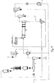
- the sewage sludge to be used is mechanically dewatered in a known dewatering device, not shown.
- a double-shaft mixer 7 the mechanically dewatered wet sludge is mixed with already thermally dried sewage sludge, which has a grain size ⁇ 1 mm, to form a homogeneous, free-flowing material.
- This free-flowing sewage sludge is fed for thermal drying to a rotary tube dryer 8 specially modified for sewage sludge, in which it is convectively dried by hot circulating air.
- the vapors loaded with water vapor are separated in a coarse separator 10 and a filter 11 from the thermally dried material entrained in the circulating air.
- the cleaned vapors are cooled in a downstream condenser 12. They give up most of their water load.
- the draining condensate is returned to the sewage treatment plant.
- the material separated in the coarse separator 10 is fed via a material line to the material coming from the rotary tube dryer 8.
- the thermally dried sewage sludge is separated into one or more grain fractions in a screening machine 9 connected downstream of the rotary tube dryer 8 on the material side.
- the screened grain fraction ⁇ 1 mm is fed to the twin-shaft mixer 7 together with the material deposited in the filter 11 as return material.
- the coarser fraction> 1 mm obtained in the screening machine 9 is fed to a storage silo 1.
- the processed material is fed via an intermediate silo 3 to a pulsation reactor 4 for combustion, the dried sewage sludge simultaneously replacing part of the fuel required for drying. Due to the high temperatures there is a complete combustion the organic pollutants and odors in the pulsation reactor 4.
- the ash produced is removed from the system and the hot flue gases are fed to a recuperator 5.
- the hot flue gas releases its sensible heat by indirect heat exchange to the dryer air coming from the condenser 12.
- the heated dryer air is again the rotary tube dryer 8 and the cooled flue gases from the pulsating combustion are fed to an exhaust gas cleaning system 6.
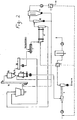
- FIG. 2 shows a variant of the circuit according to the invention for drying and burning the sewage sludge.
- the main difference compared to variant 1 is that the thermally dried sewage sludge is ground in a spring roller mill 13 instead of the agitator ball mill 2.
- the sewage sludge thermally dried in the rotary tube dryer 8 is fed in via a material line of a spring roller mill 13 for grinding.
- the ground sewage sludge reaches a circulating air classifier 15 via a bucket elevator 14, the grains separated in the circulating air classifier 15 being fed to a conveyor 16.
- a part of the material is fed back to the twin-shaft mixer 7 as the material to be returned, while the other part is fed back to the spring roller mill 13.
- the material separated in the coarse separator 10 and in the filter 11 reaches the bucket elevator 14 and / or the intermediate silo 3 downstream of the air classifier 15 via a common material line.
- the processed material from the intermediate silo 3, as described in variant 1, is fed to a pulsation reactor 4 for combustion, the hot flue gases of the pulsation reactor 4 also being used for indirect heat exchange with the dryer circulating air.
Abstract
Description
Die Erfindung betrifft ein Verfahren und die dazugehöhrige Anlage zur Trocknung und Verbrennung von Abfallstoffen, insbesondere von Klärschlamm, wobei die Abfallstoffe nach mechanischer und thermischer Entwässerung verbrannt werden.The invention relates to a method and the associated plant for drying and burning waste materials, in particular sewage sludge, the waste materials being burned after mechanical and thermal dewatering.
Durch die ständig steigenden Anforderungen an die Abwasserreinigung erhöht sich die Menge an Klärschlamm. Im Jahre 2000 ist von ca. 3,3 Mill. Tonnen Trockensubstanz auszugenen, die entsorgt bzw. verwertet werden müssen.Due to the constantly increasing demands on wastewater treatment, the amount of sewage sludge increases. In the year 2000, approx. 3.3 million tons of dry matter have to be disposed of, which must be disposed of or recycled.
Eine Deponierung wird für die Zukunft aus zwei Gründen schwieriger. Erstens wird die Schaffung von genügend Deponieraum immer problematischer und zweitens wird die Ablagerung organischer Substanzen nach Einführung der TA Siedlungsabfall immer mehr eingeschränkt.Landfilling will become more difficult for the future for two reasons. Firstly, the creation of sufficient landfill space is becoming increasingly problematic and secondly, the deposition of organic substances is being increasingly restricted after the introduction of TA municipal waste.
Die Akzeptanz für eine landwirtschaftliche Nutzung ist auf Grund der Schadstoffgehalte kaum gegeben. Für diese Art der Verwertung kommen somit nur wenig belastete Klärschlämme in Frage. Somit bietet sich als einzige Alternative die thermische Verwertung an.Due to the pollutant content, there is hardly any acceptance for agricultural use. Slightly contaminated sewage sludge is therefore an option for this type of recycling. Thermal recycling is therefore the only alternative.
Zur thermischen Verwertung von Klärschlämmen sind eine Vielzahl von Verfahren entwickelt worden, bei denen die Klärschlämme nach einer Trocknung verbrannt werden. Die dabei entstandene Abwärme wird teilweise zur Gewinnung von Nutzenergie und teilweise zur Trocknung des Klärschlammes verwendet.A multitude of processes have been developed for the thermal utilization of sewage sludge, in which the sewage sludge is burned after drying. The waste heat generated is used partly to obtain useful energy and partly to dry the sewage sludge.
So erfolgt gemäß der US 2 148 447 die Verbrennung der vorher mechnisch und thermisch Abfallstoffe, wie z.B. Klärschlamm, in einer Brennkammer.According to US Pat. No. 2,148,447, the previously mechanically and thermally waste materials, such as sewage sludge, are burned in a combustion chamber.
Diese Verfahren haben den Nachteil, daß der Verbrennung des getrockneten Schlammes eine aufwendige Rauchgaswäsche nachgeschaltet werden muß. Ferner entstehen bei der Schlammtrocknung geruchsbelaestigende Brüden, deren Geruchstoffe kostenaufwendig beseitigt werden müssen.These processes have the disadvantage that the combustion of the dried sludge has to be followed by a complex flue gas scrubbing. Furthermore, vapors which cause odors are created during the drying of the sludge, the odor substances of which have to be removed in a costly manner.
Zur Beseitigung dieser Nachteile ist es gemäß der DE 35 42 004 bekannt, Schlämme aus Kläranlagen beim Zementherstellungsprozeß thermisch zu verwerten. Dabei werden die Schlämme mit einem Teil der bei der Zementklinkerkühlung anfallenden heißen Abluft getrocknet und danach dem Zementklinkerherstellungsprozeß als Sekundärbrennstoff zugeführt. Durch die hohen Betriebstemperaturen ist eine sichere Entsorgungsmöglichkeit der Klärschlämme gegeben. Die in den Klärschlämmen enthaltenen Schadstoffe werden immobil im erzeugten Zementklinker eingebunden.To eliminate these disadvantages, it is known from DE 35 42 004 to thermally utilize sludges from sewage treatment plants in the cement manufacturing process. The sludge is dried with part of the hot exhaust air from the cement clinker cooling and then fed to the cement clinker manufacturing process as a secondary fuel. The high operating temperatures mean that the sewage sludge can be disposed of safely. The pollutants contained in the sewage sludge are immobilized in the cement clinker produced.
Nachteilig dabei ist, daß für die Klärschlämme teilweise lange Anfahrtswege benötigt werden um sie in einem Zementwerk verwerten zu können. Außerdem werden durch die Hg- und Cl- Gehalte des Klärschlammes die Einsatzgrenzen für die Zugabe des Klärschlammes als Sekundärbrennstoff beim Zementherstellungsprozeß bestimmt.The disadvantage here is that the sewage sludge sometimes requires long journeys to be able to use it in a cement plant. In addition, the limits of use for the addition of the sewage sludge as a secondary fuel in the cement production process are determined by the Hg and Cl contents of the sewage sludge.
Die Aufgabe der Erfindung besteht darin, ein Verfahren und die dazugehöhrige anlagentechnische Schaltung zur Trocknung und Verbrennung von Abfallstoffen, insbesondere von Klärschlamm, zu entwickeln, mit dem wirtschaftlich und ohne zusätzliche Belastung der Umwelt eine vollständige Verbrennung der organischen Schad- und Geruchstoffe bei einer hohen Verfügbarkeit der Anlage erreicht wird.The object of the invention is to develop a method and the associated technical circuit for drying and burning waste materials, in particular sewage sludge, with which complete combustion of the organic pollutants and odorous substances with high availability is economical and without additional pollution of the environment the system is reached.
Erfindungsgemäß wird das dadurch erreicht, daß die Abfallstoffe, insbesondere Klärschlamm, nach mechanischer Entwässerung und thermischer Trocknung durch heiße Umluft aufgemahlen und danach in einem Pulsationsreaktor pulsierend verbrannt werden, wobei die Abfallstoffe gleichzeitig als ein Teil des Brennstoffbedarfs für die pulsierende Verbrennung dienen.According to the invention this is achieved in that the waste materials, in particular sewage sludge, after mechanical dewatering and thermal drying, are ground by hot circulating air and then pulsed in a pulsation reactor, the waste materials simultaneously being part of the fuel requirement for the pulsating Serve combustion.
Ein Teil der thermisch getrockneten Abfallstoffe mit einer Korngroesze < lmm wird als Rückführgut dem Prozeß nach der mechanischen Entwässerung wieder aufgegeben, um sie dort mit dem entwässerten Naßschlamm zu einem homogenen rieselfähigen Gut zu verarbeiten.Some of the thermally dried waste with a grain size <1 mm is returned to the process after mechanical dewatering as a return material in order to process it there with the dewatered wet sludge to form a homogeneous, free-flowing material.
Die Umluft zur thermischen Trocknung des rieselfähigen Gutes wird durch indirekten Wärmetausch mit den Abgasen der pulsierenden Verbrennung aufgeheizt und einem Drehrohrtrockner zugeführt.The circulating air for thermal drying of the free-flowing material is heated by indirect heat exchange with the exhaust gases of the pulsating combustion and fed to a rotary tube dryer.
Die Anlage zur Trocknung und Verbrennung von Abfallstoffen besteht aus einem Drehrohrtrockner zur thermischen Trocknung des bereits vorher mechanisch entwässerten und rieselfähig gemachten Gutes, dem materialseitig eine Aufbereitungsanlage und gasseitig ein Grobabscheider, ein Filter und ein Kondensator nachgeschaltet sind.The plant for drying and incinerating waste materials consists of a rotary tube dryer for the thermal drying of the goods that have already been mechanically dewatered and made free-flowing.
Die Aufbereitungsanlage besteht aus einer an sich bekannten Mahlanlage zur Aufmahlung der thermisch getrockneten Abfallstoffe. Ein Teil der thermisch getrockneten Abfallstoffe mit einer Korngröße < 1 mm wird mittels einer Siebmaschine oder einem Sichter abgeschieden und über eine Materialleitung dem materialseitig dem Drehrohrtrockner vorgeschalteten Doppelwellenmischer als Rückführgut zugeführt. Der in einer Rührwerkskugelmühle oder Federrollenmühle aufgemahlene thermisch getrocknete Abfallstoff wird über ein Zwischensilo dem nachgeschalteten Pulsationsreaktor zur Verbrennung aufgegeben.The processing plant consists of a known grinding plant for grinding the thermally dried waste materials. Some of the thermally dried waste with a grain size of <1 mm is separated off by means of a screening machine or a classifier and fed via a material line to the double-shaft mixer upstream of the rotary tube dryer as return material. The thermally dried waste material ground in an agitator ball mill or spring roller mill is fed to the downstream pulsation reactor for combustion via an intermediate silo.
Die heißen Abgase, die bei der Abfallverbrennung im Pulsationsreaktor entstehen, werden über eine Leitung einem Rekuperator zugeführt, in den ebenfalls die Umluftleitung von dem Kondensator mündet. Die im Rekuperator indirekt aufgeheizte Umluft von dem Kondensator wird über eine Rohrleitung dem Drehrohrtrockner wieder zugeführt.The hot exhaust gases that are generated during waste incineration in the pulsation reactor are fed via a line to a recuperator, into which the recirculation line from the condenser also flows. The circulating air from the condenser, which is indirectly heated in the recuperator, is fed back to the rotary tube dryer via a pipe.
Die Abgase des Pulsationsreaktors werden nach verlassen des Rekuperators einer Abgasreinigung aufgegeben.The exhaust gases from the pulsation reactor are released after the recuperator has been cleaned.
Der Vorteil der erfindungsgemäßen Lösung besteht darin, daß durch den einfachen und robusten Aufbau einer Trocknungsanlage mit indirekt beheiztem Drehrohrtrockner eine hohe Verfügbarkeit und Wirtschaftlichkeit der Anlage erreicht wird. Außerdem wird durch die anlagentechnische Schaltung ein durchgehender Betrieb ohne dauernde Bedienung der Anlage erzielt. Die Wirtschaftlichkeit des Verfahrens und der Anlage wird auch dadurch erreicht, daß die fühlbare Wärme der bei der Verbrennung der Abfallstoffe entstehenden heißen Abgase durch indirekten Wärmetausch mit der Umluft des Trocknerkreislaufes genutzt werden kann. Außerdem wird der für die Verbrennung der Abfallstoffe benötigte Brennstoff teilweise oder gänzlich durch die Abfallstoffe selbst geliefert, so daß auch eine wirtschaftliche Verbrennung der Abfallstoffe erfolgt.The advantage of the solution according to the invention is that the simple and robust construction of a drying system with an indirectly heated rotary tube dryer achieves high availability and economy of the system. In addition, continuous operation without continuous operation of the system is achieved through the technical circuit. The economy of the process and the system is also achieved in that the sensible heat of the hot exhaust gases produced during the combustion of the waste materials can be used by indirect heat exchange with the circulating air of the dryer circuit. In addition, some or all of the fuel required for the combustion of the waste materials is supplied by the waste materials themselves, so that the waste materials are also burned economically.
Durch die hohen Temperaturen im Pulsationsreaktor erfolgt eine vollständige Verbrennung der organischen Schad- und Geruchsstoffe mit einem geringen Ascheanfall, der dann probemlos deponiert werden kann. Schwermetalle werden immobil in der Asche eingelagert.Due to the high temperatures in the pulsation reactor, there is a complete combustion of the organic pollutants and odorants with a small amount of ash, which can then be deposited without any problems. Heavy metals are immobilized in the ashes.
Ein weiterer Vorteil der Erfindung besteht in der lufttechnischen Trennung des Trocknerkreislaufes von dem Heizkreislauf zur Verbrennung der Abfallstoffe.Another advantage of the invention is the ventilation separation of the dryer circuit from the heating circuit for the combustion of the waste materials.
Die Erfindung wird anhand von Ausführungsbeispielen näher erläutert. Die dazugehoerige Zeichnungen zeigen:
- Fig. 1:
- die erfindungsgemäße anlagentechnische Schaltung zur Trocknung und Verbrennung von Abfallstoffen
- Fig. 2:
- eine Variante der erfindungsgemäßen Schaltung zur Trocknung und Verbrennung von Abfallstoffen
- Fig. 1:
- the technical system circuit for drying and burning waste materials
- Fig. 2:
- a variant of the circuit according to the invention for drying and burning waste materials
Gemäß Figur 1 wird der zu verwertende Klärschlamm in einer nichtdargestellten bekannten Entwässerungseinrichtung mechanisch entwässert. In einem Doppelwellenmischer 7 wird der mechanisch entwässerte Naßschlamm mit bereits thermisch getrocknetem Klärschlamm, der eine Korngröße < 1mm besitzt, zu einem homogenen rieselfähigen Gut vermischt. Dieser rieselfähige Klärschlamm wird zur thermischen Trocknung einem speziell für Klärschlamm modifizierten Drehrohrtrockner 8 aufgegeben, in dem er durch heiße Umluft konvektiv getrocknet wird.According to FIG. 1, the sewage sludge to be used is mechanically dewatered in a known dewatering device, not shown. In a double-shaft mixer 7, the mechanically dewatered wet sludge is mixed with already thermally dried sewage sludge, which has a grain size <1 mm, to form a homogeneous, free-flowing material. This free-flowing sewage sludge is fed for thermal drying to a
Die mit Wasserdampf beladenen Brüden werden in einem Grobabscheider 10 und einem Filter 11 von dem mit der Umluft mitgerissenen thermisch getrocknetem Material getrennt. Die gereinigten Brüden werden in einem nachgeschalteten Kondensator 12 abgekühlt. Dabei geben sie den Großteil ihrer Wasserbeladung ab. Das abfließende Kondensat wird zurück in die Kläranlage geführt.The vapors loaded with water vapor are separated in a
Das im Grobabscheider 10 abgeschiedene Material wird über eine Materialleitung dem aus dem Drehrohrtrockner 8 kommenden Material zugeführt. In einer dem Drehrohrtrockner 8 materialseitig nachgeschalteten Siebmaschine 9 erfolgt eine Trennung des thermisch getrockneten Klärschlammes in eine oder mehrere Kornfraktionen. Die abgesiebte Kornfraktion < 1mm wird zusammen mit dem im Filter 11 abgeschiedenen Material als Rückführgut dem Doppelwellenmischer 7 aufgegeben.The material separated in the
Die in der Siebmaschine 9 anfallende gröbere Fraktion > 1 mm wird einem Vorratssilo 1 zugeführt. Nach Aufmahlung des thermisch getrockneten Klärschlammes mit einer Korngröße ≥ 1mm in einer Rührwerkskugelmühle 2 wird das aufbereitete Material über ein Zwischensilo 3 zur Verbrennung einem Pulsationsreaktor 4 aufgegeben, wobei der getrocknete Klärschlamm gleichzeitig einen Teil des für die Trocknung benötigten Brennstoffes ersetzt. Infolge der hohen Temperaturen erfolgt eine vollständige Verbrennung der organischen Schad- und Geruchsstoffe im Pulsationsreaktor 4.The coarser fraction> 1 mm obtained in the
Als Verbrennungsluft für die pulsierende Verbrennung wird dem Pulsationsreaktor 4 Frischluft und der Teil der vom Kondensator 12 abgeführten Trocknerluft zugeführt, der nicht unmittelbar zur Trocknung benötigt wird.Fresh air and the part of the dryer air discharged from the
Nach der Verbrennung des Klärschlammes wird die anfallende Asche aus dem System ausgetragen und die heißen Rauchgase einem Rekuperator 5 zugeführt. Im Rekuperator 5 gibt das heiße Rauchgas seine fühlbare Wärme durch indirekten Wärmetausch an die von dem Kondensator 12 kommende Trocknerluft ab. Die aufgeheizte Trocknerumluft wird wieder dem Drehrohrtrockner 8 und die abgekühlten Rauchgase von der pulsierenden Verbrennung werden einer Abgasreinigung 6 zugeführt.After the sewage sludge has been burned, the ash produced is removed from the system and the hot flue gases are fed to a recuperator 5. In the recuperator 5, the hot flue gas releases its sensible heat by indirect heat exchange to the dryer air coming from the
Die Figur 2 zeigt eine Variante der erfindungsgemäßen Schaltung zur Trocknung und Verbrennung des Klärschlammes. Der wesentliche Unterschied gegenueber der Variante 1 besteht darin, daß die Aufmahlung des thermisch getrockneten Klärschlammes in einer Federrollenmuehle 13 an Stelle der Rührwerkskugelmühle 2 erfolgt. Dabei wird der im Drehrohrtrockner 8 thermisch getrocknete Klärschlamm über eine Materialleitung einer Federrollenmühle 13 zur Aufmahlung aufgegeben. über ein Becherwerk 14 gelangt der aufgemahlene Klärschlamm in einen Umluftsichter 15, wobei die im Umluftsichter 15 abgeschiedenen Grieße einem Förderer 16 zugeführt werden. Dabei wird eine Teilmaterialmenge als Rückführgut dem Doppelwellenmischer 7 aufgegeben während der andere Teil der Federrollenmühle 13 wieder zugeführt wird.FIG. 2 shows a variant of the circuit according to the invention for drying and burning the sewage sludge. The main difference compared to variant 1 is that the thermally dried sewage sludge is ground in a
Das im Grobabscheider 10 und im Filter 11 abgeschiedene Material gelangt über eine gemeinsame Materialleitung in das Becherwerk 14 und/oder in das dem Umluftsichter 15 nachgeschaltete Zwischensilo 3.The material separated in the
Das aufbereitete Material aus dem Zwischensilo 3 wird, wie in Variante 1 beschrieben, zur Verbrennung einem Pulsationsreaktor 4 aufgegeben, wobei ebenfalls die heißen Rauchgase des Pulsationsreaktors 4 zum indirekten Wärmetausch mit der Trocknerumluft genutzt werden.The processed material from the
Aufstellung der verwendeten Bezugszeichen
- 1.
- Vorratssilo
- 2.
- Rührwerkskugelmühle
- 3.
- Zwischensilo
- 4.
- Pulsationsreaktor
- 5.
- Rekuperator
- 6.
- Abgasreinigung
- 7.
- Doppelwellenmischer
- 8.
- Drehrohrtrockner
- 9.
- Siebmaschine
- 10.
- Grobabscheider
- 11.
- Filter
- 12.
- Kondensator
- 13.
- Federrollenmühle
- 14.
- Becherwerk
- 15.
- Umluftsichter
- 16.
- Förderer
- 1.
- Storage silo
- 2nd
- Agitator ball mill
- 3rd
- Intermediate silo
- 4th
- Pulsation reactor
- 5.
- Recuperator
- 6.
- Exhaust gas cleaning
- 7.
- Double shaft mixer
- 8th.
- Rotary tube dryer
- 9.
- Screening machine
- 10th
- Coarse separator
- 11.
- filter
- 12th
- capacitor
- 13.
- Spring roller mill
- 14.
- Bucket elevator
- 15.
- Circulating air classifier
- 16.
- Sponsor
Claims (10)
- Process to dry and burn waste products, in particular sewage sludge. The waste products are burnt after mechanical and thermal dewatering, characterized in that part of the thermally dried waste with a grain size of ≥ 1 mm is ground and then burnt in a reactor by pulsed combustion, that the residue of the thermally dried waste having a grain size of < 1 mm is returned to the process after mechanical dewatering, and that the heat energy of the exit gases of the pulsed combustion is used as drying energy due to indirect heat exchange.
- Plant to carry out the process of claim 1 using a mechanical dewatering equipment, a rotary dryer and a combustion unit, characterized in that the rotary dryer (8) is followed by an actually known screening machine (9), grinding plant, intermediate silo (3) and a pulsed reactor (4), as regards the material, and by a coarse separator (10), filter (11) and condenser (12), as regards the gas, and that the exhaust-gas duct of the pulsed reactor (4) as well as the circulating air duct of the condenser (12) lead into a recuperator (5) where the dryer gas is heated up by the condenser (12) due to indirect heat exchange and returned to the rotary dryer (8) via a pipeline arranged between the recuperator (5) and the rotary dryer (8).
- The plant of claim 2, characterized in that an exhaust-gas bypass duct from the condenser (12) is led into the supply line of combustion air of the pulsed reactor (4).
- Plant of claims 2 and 3, characterized in that the grinding plant following the rotary dryer (8) consists of a screening machine (9) with following storage silo (1) and agitator ball mill (2).
- Plant of claim 4, characterized in that the screening machine (9) is connected to the storage silo (1) via a material duct to discharge the waste products with a grain size ≥ 1 mm.
- Plant of claims 4 and 5, characterized in that the material duct of the filter (11) and the material duct of the screening machine (9) in which the waste products with a grain size < 1 mm are discharged are both led into a double-shaft mixer (7) arranged in front of the rotary dryer (8).
- Plant of claims 4 to 6, characterized in that the material duct of the coarse separator (10) is led into the material duct arranged between the rotary dryer (8) and the screening machine (9).
- Plant of claims 3 and 4, characterized in that the grinding plant following the rotary dryer (8) consists of a spring-loaded roller mill (13) with following classifying unit, e.g. bucket elevator (14) and circulating air separator (15).
- Plant of claim 8, characterized in that the material ducts of the coarse separator (10) and the filter (11) end in a joint material duct led into the bucket elevator (14) and/or the intermediate silo (3).
- Plant of claims 8 and 9, characterized in that the tailings duct of the circulating air separator (15) is connected to a conveyor (16), and that a material duct of the conveyor (16) in which part of the waste having a size < 1 is discharged, is connected to the double-shaft mixer (7).
Applications Claiming Priority (2)
| Application Number | Priority Date | Filing Date | Title |
|---|---|---|---|
| DE4217729 | 1992-05-29 | ||
| DE4217729A DE4217729A1 (en) | 1992-05-29 | 1992-05-29 | Process and technical circuit for drying and burning waste materials |
Publications (3)
| Publication Number | Publication Date |
|---|---|
| EP0571722A2 EP0571722A2 (en) | 1993-12-01 |
| EP0571722A3 EP0571722A3 (en) | 1994-02-23 |
| EP0571722B1 true EP0571722B1 (en) | 1996-05-15 |
Family
ID=6459956
Family Applications (1)
| Application Number | Title | Priority Date | Filing Date |
|---|---|---|---|
| EP93103730A Expired - Lifetime EP0571722B1 (en) | 1992-05-29 | 1993-03-09 | Process and plant layout for drying and burning waste materials |
Country Status (3)
| Country | Link |
|---|---|
| EP (1) | EP0571722B1 (en) |
| AT (1) | ATE138177T1 (en) |
| DE (2) | DE4217729A1 (en) |
Cited By (2)
| Publication number | Priority date | Publication date | Assignee | Title |
|---|---|---|---|---|
| CN102633420A (en) * | 2012-05-09 | 2012-08-15 | 江苏中容环保有限公司 | Sludge pyrolysis device with functions of porous medium heat accumulating, material equalizing, pre-heating and drying |
| CN110242968A (en) * | 2019-06-21 | 2019-09-17 | 南通欣源污泥处置科技有限公司 | It is a kind of burning and fume treatment dewatered sludge blanking device |
Families Citing this family (6)
| Publication number | Priority date | Publication date | Assignee | Title |
|---|---|---|---|---|
| DE4431564A1 (en) * | 1994-07-13 | 1996-01-18 | Kloeckner Humboldt Deutz Ag | Process and technical circuit for drying and burning sewage sludge |
| EP0692679A3 (en) | 1994-07-13 | 1997-01-02 | Kloeckner Humboldt Deutz Ag | Method and plant layout for drying and incinerating sewage sludge |
| NL1035274C2 (en) * | 2008-04-09 | 2009-10-12 | Internationaal Projectbureau H | Organic material containing sludge i.e. undiluted and relatively wet sewage sludge, processing method for wastewater treatment plant, involves drying sludge by using pulsating combustor, where portion of dried sludge is used as fuel |
| DE102009010118B4 (en) * | 2009-02-24 | 2011-03-31 | Michael Kaden | Process for the automatic incineration of sewage sludge |
| CN105399304B (en) * | 2015-12-25 | 2017-12-01 | 柳建国 | Biological sludge drying and incineration circulation process method and its complete set of equipments |
| DE102019120642B4 (en) * | 2019-07-31 | 2022-03-17 | 5-Haven Holding GmbH | Process and device for recycling organic waste materials |
Family Cites Families (11)
| Publication number | Priority date | Publication date | Assignee | Title |
|---|---|---|---|---|
| US2148447A (en) * | 1933-08-26 | 1939-02-28 | William A Dundas | Method of and apparatus for disposing of sewage waste |
| DE1207896B (en) * | 1961-05-17 | 1965-12-23 | Kohlenscheidungs Ges Mit Besch | Process for incinerating thickened sewage sludge and drying and incineration systems for this |
| SU361983A1 (en) * | 1970-06-02 | 1972-12-13 | METHOD OF BURNING DRAIN SEDIMENTATION | |
| CH540858A (en) * | 1972-07-31 | 1973-08-31 | Von Roll Ag | Process for drying and subsequent incineration of sludge and installation for carrying out the process |
| US3954069A (en) * | 1975-03-10 | 1976-05-04 | Myrens Verksted A/S | Process and apparatus for the incineration of aqueous sewage sludge |
| CH641133A5 (en) * | 1979-05-28 | 1984-02-15 | Escher Wyss Ag | METHOD FOR PROCESSING CLEANING SLUDGE. |
| DE3429055A1 (en) * | 1984-08-07 | 1986-02-20 | Heiner Dipl.-Ing. 4030 Ratingen Kreyenberg | Process for the disposal of sludges, in particular sewage sludges and septic sludges |
| DE3542004A1 (en) * | 1985-11-28 | 1987-06-04 | Kloeckner Humboldt Deutz Ag | Drying and combustion of sludges in the firing of mineral materials |
| DE3839861A1 (en) * | 1988-11-25 | 1990-05-31 | Rudi Pedersen | HEATING SYSTEM |
| DE3915082C1 (en) * | 1989-05-09 | 1990-09-27 | Deutsche Babcock Anlagen Ag, 4200 Oberhausen, De | |
| US4926764A (en) * | 1989-08-17 | 1990-05-22 | Den Broek Jos Van | Sewage sludge treatment system |
-
1992
- 1992-05-29 DE DE4217729A patent/DE4217729A1/en not_active Withdrawn
-
1993
- 1993-03-09 EP EP93103730A patent/EP0571722B1/en not_active Expired - Lifetime
- 1993-03-09 AT AT93103730T patent/ATE138177T1/en not_active IP Right Cessation
- 1993-03-09 DE DE59302568T patent/DE59302568D1/en not_active Expired - Fee Related
Cited By (2)
| Publication number | Priority date | Publication date | Assignee | Title |
|---|---|---|---|---|
| CN102633420A (en) * | 2012-05-09 | 2012-08-15 | 江苏中容环保有限公司 | Sludge pyrolysis device with functions of porous medium heat accumulating, material equalizing, pre-heating and drying |
| CN110242968A (en) * | 2019-06-21 | 2019-09-17 | 南通欣源污泥处置科技有限公司 | It is a kind of burning and fume treatment dewatered sludge blanking device |
Also Published As
| Publication number | Publication date |
|---|---|
| EP0571722A3 (en) | 1994-02-23 |
| DE59302568D1 (en) | 1996-06-20 |
| ATE138177T1 (en) | 1996-06-15 |
| EP0571722A2 (en) | 1993-12-01 |
| DE4217729A1 (en) | 1993-12-02 |
Similar Documents
| Publication | Publication Date | Title |
|---|---|---|
| EP0343431B1 (en) | Process and apparatus for sewage sludge drying | |
| EP0459603B1 (en) | Process and apparatus for continuous drying of wood chips, wood fibres or other bulk materials | |
| EP0461305B1 (en) | Process for the purification of exhaust gases of plants for the production of cement clinker | |
| EP0459194B1 (en) | Process for the thermal disposal of sludge | |
| EP0515792A2 (en) | Method for treating residues from a waste incineration plant and waste incineration plant for carrying out said method | |
| DE3542004A1 (en) | Drying and combustion of sludges in the firing of mineral materials | |
| EP0465479B1 (en) | A method of reprocessing sewage sludge | |
| EP0423400B1 (en) | Waste disposal device | |
| EP0716264B1 (en) | Method and installation for sludge combustion | |
| CH687441A5 (en) | Method and apparatus for processing slag from waste incineration plants | |
| DE19654043A1 (en) | Thermal dryer with exhaust gas cleaning, afterburning e.g. for wood chips | |
| DE3635068C2 (en) | ||
| WO1989012609A1 (en) | Process and device for processing residues from refuse incinerators | |
| EP0571722B1 (en) | Process and plant layout for drying and burning waste materials | |
| DE19531379C1 (en) | Process for the incineration of sewage sludge and plant for carrying out the process | |
| EP0692679A2 (en) | Method and plant layout for drying and incinerating sewage sludge | |
| DE4404284A1 (en) | Arrangement and method for environmentally friendly flue gas cleaning | |
| DE2726157B2 (en) | Kiln plant for solid goods | |
| AT3735U1 (en) | METHOD AND DEVICE FOR DRYING SEWAGE SLUDGE | |
| DE2535683A1 (en) | METHOD AND DEVICE FOR INCINERATION OF SLUDGE WITH THE HELP OF RECUPERATIVE SLUDGE DRYING | |
| DE3537595A1 (en) | Method and installation for utilising moist waste, in particular sewage sludge | |
| DE4431564A1 (en) | Process and technical circuit for drying and burning sewage sludge | |
| EP0526458B1 (en) | Process and equipment for utilizing sewage sludge | |
| DE19956562A1 (en) | Process for cleaning a heat exchanger surface and solid blowing medium for carrying out the process | |
| EP1378494B1 (en) | Process and apparatus for treating biogenic residues, in particular sludges |
Legal Events
| Date | Code | Title | Description |
|---|---|---|---|
| PUAI | Public reference made under article 153(3) epc to a published international application that has entered the european phase |
Free format text: ORIGINAL CODE: 0009012 |
|
| AK | Designated contracting states |
Kind code of ref document: A2 Designated state(s): AT CH DE DK FR LI NL SE |
|
| PUAL | Search report despatched |
Free format text: ORIGINAL CODE: 0009013 |
|
| AK | Designated contracting states |
Kind code of ref document: A3 Designated state(s): AT CH DE DK FR LI NL SE |
|
| 17P | Request for examination filed |
Effective date: 19940310 |
|
| 17Q | First examination report despatched |
Effective date: 19950313 |
|
| RAP1 | Party data changed (applicant data changed or rights of an application transferred) |
Owner name: HUMBOLDT WEDAG ZAB GMBH |
|
| GRAH | Despatch of communication of intention to grant a patent |
Free format text: ORIGINAL CODE: EPIDOS IGRA |
|
| GRAA | (expected) grant |
Free format text: ORIGINAL CODE: 0009210 |
|
| AK | Designated contracting states |
Kind code of ref document: B1 Designated state(s): AT CH DE DK FR LI NL SE |
|
| PG25 | Lapsed in a contracting state [announced via postgrant information from national office to epo] |
Ref country code: NL Free format text: LAPSE BECAUSE OF FAILURE TO SUBMIT A TRANSLATION OF THE DESCRIPTION OR TO PAY THE FEE WITHIN THE PRESCRIBED TIME-LIMIT Effective date: 19960515 Ref country code: DK Effective date: 19960515 |
|
| REF | Corresponds to: |
Ref document number: 138177 Country of ref document: AT Date of ref document: 19960615 Kind code of ref document: T |
|
| REF | Corresponds to: |
Ref document number: 59302568 Country of ref document: DE Date of ref document: 19960620 |
|
| ET | Fr: translation filed | ||
| PG25 | Lapsed in a contracting state [announced via postgrant information from national office to epo] |
Ref country code: SE Effective date: 19960815 |
|
| NLV1 | Nl: lapsed or annulled due to failure to fulfill the requirements of art. 29p and 29m of the patents act | ||
| PLBE | No opposition filed within time limit |
Free format text: ORIGINAL CODE: 0009261 |
|
| STAA | Information on the status of an ep patent application or granted ep patent |
Free format text: STATUS: NO OPPOSITION FILED WITHIN TIME LIMIT |
|
| PG25 | Lapsed in a contracting state [announced via postgrant information from national office to epo] |
Ref country code: LI Effective date: 19970331 Ref country code: CH Effective date: 19970331 |
|
| 26N | No opposition filed | ||
| REG | Reference to a national code |
Ref country code: CH Ref legal event code: PL |
|
| PGFP | Annual fee paid to national office [announced via postgrant information from national office to epo] |
Ref country code: DE Payment date: 19980223 Year of fee payment: 6 Ref country code: AT Payment date: 19980223 Year of fee payment: 6 |
|
| PGFP | Annual fee paid to national office [announced via postgrant information from national office to epo] |
Ref country code: FR Payment date: 19980226 Year of fee payment: 6 |
|
| PG25 | Lapsed in a contracting state [announced via postgrant information from national office to epo] |
Ref country code: AT Free format text: LAPSE BECAUSE OF NON-PAYMENT OF DUE FEES Effective date: 19990309 |
|
| PG25 | Lapsed in a contracting state [announced via postgrant information from national office to epo] |
Ref country code: FR Free format text: LAPSE BECAUSE OF NON-PAYMENT OF DUE FEES Effective date: 19991130 |
|
| REG | Reference to a national code |
Ref country code: FR Ref legal event code: ST |
|
| PG25 | Lapsed in a contracting state [announced via postgrant information from national office to epo] |
Ref country code: DE Free format text: LAPSE BECAUSE OF NON-PAYMENT OF DUE FEES Effective date: 20000101 |