EP0571200A1 - Recording head apparatus for a tape player - Google Patents
Recording head apparatus for a tape player Download PDFInfo
- Publication number
- EP0571200A1 EP0571200A1 EP93303889A EP93303889A EP0571200A1 EP 0571200 A1 EP0571200 A1 EP 0571200A1 EP 93303889 A EP93303889 A EP 93303889A EP 93303889 A EP93303889 A EP 93303889A EP 0571200 A1 EP0571200 A1 EP 0571200A1
- Authority
- EP
- European Patent Office
- Prior art keywords
- head
- recording
- tape
- reproducing
- erase
- Prior art date
- Legal status (The legal status is an assumption and is not a legal conclusion. Google has not performed a legal analysis and makes no representation as to the accuracy of the status listed.)
- Granted
Links
Images


Classifications
-
- G—PHYSICS
- G11—INFORMATION STORAGE
- G11B—INFORMATION STORAGE BASED ON RELATIVE MOVEMENT BETWEEN RECORD CARRIER AND TRANSDUCER
- G11B15/00—Driving, starting or stopping record carriers of filamentary or web form; Driving both such record carriers and heads; Guiding such record carriers or containers therefor; Control thereof; Control of operating function
- G11B15/02—Control of operating function, e.g. switching from recording to reproducing
-
- G—PHYSICS
- G11—INFORMATION STORAGE
- G11B—INFORMATION STORAGE BASED ON RELATIVE MOVEMENT BETWEEN RECORD CARRIER AND TRANSDUCER
- G11B5/00—Recording by magnetisation or demagnetisation of a record carrier; Reproducing by magnetic means; Record carriers therefor
- G11B5/48—Disposition or mounting of heads or head supports relative to record carriers ; arrangements of heads, e.g. for scanning the record carrier to increase the relative speed
- G11B5/54—Disposition or mounting of heads or head supports relative to record carriers ; arrangements of heads, e.g. for scanning the record carrier to increase the relative speed with provision for moving the head into or out of its operative position or across tracks
- G11B5/55—Track change, selection or acquisition by displacement of the head
- G11B5/5513—Specially adapted for transducing in both travelling directions of tape
- G11B5/5517—Controlled by automatic tape drive reversing arrangement
-
- G—PHYSICS
- G11—INFORMATION STORAGE
- G11B—INFORMATION STORAGE BASED ON RELATIVE MOVEMENT BETWEEN RECORD CARRIER AND TRANSDUCER
- G11B15/00—Driving, starting or stopping record carriers of filamentary or web form; Driving both such record carriers and heads; Guiding such record carriers or containers therefor; Control thereof; Control of operating function
- G11B15/02—Control of operating function, e.g. switching from recording to reproducing
- G11B15/10—Manually-operated control; Solenoid-operated control
- G11B15/106—Manually-operated control; Solenoid-operated control mechanically operated
-
- G—PHYSICS
- G11—INFORMATION STORAGE
- G11B—INFORMATION STORAGE BASED ON RELATIVE MOVEMENT BETWEEN RECORD CARRIER AND TRANSDUCER
- G11B15/00—Driving, starting or stopping record carriers of filamentary or web form; Driving both such record carriers and heads; Guiding such record carriers or containers therefor; Control thereof; Control of operating function
- G11B15/18—Driving; Starting; Stopping; Arrangements for control or regulation thereof
- G11B15/44—Speed-changing arrangements; Reversing arrangements; Drive transfer means therefor
- G11B15/442—Control thereof
Definitions
- the present invention generally relates to recording and reproducing apparatus and, more particularly, to a recording and reproducing apparatus having an auto-reverse function in which a recording and reproducing head and an erase head are both of reversible types.
- an auto-reverse recording and reproducing apparatus One conventional recording and reproducing apparatus that can record or reproduce a tape during the tape is transported in the positive and reverse directions is generally referred to as an auto-reverse recording and reproducing apparatus.
- the tape can be automatically recorded or reproduced during the tape is transported in the positive direction while the tape loading state and the operation unit setting condition need not be changed at all when the tape reaches its end. Also, during the tape is transported in the reverse direction, the tape can be recorded or reproduced automatically. Therefore, the auto-reverse function is useful particularly when a recording or reproduction of a long time is required.
- Another conventional auto-reverse recording and reproducing apparatus utilizes a four-channel recording and reproducing head whose erase heads are opposed to small windows of a cassette half.
- the former recording and reproducing apparatus employs the erase head of a coil-type head utilizing an AC bias.
- Such coil-type erase head is expensive and the erase head must be disposed in a limited small space. Therefore, if the tape is curled at the guide portion when a tape path of head is adjusted, then the state that the tape is in contact with the erase head is affected. There is then the problem that the tape is not erased completely.
- the latter recording and reproducing apparatus needs two erase heads and therefore becomes expensive. Also, because characteristics of the two erase heads are not the same, erasing characteristics that the two erase heads present during the tape is transported in the positive direction and in the reverse direction are fluctuated. Furthermore, the number of tape guides is increased as the number of erase heads is increased. There is then the problem that adjustment of tape path becomes troublesome.
- a recording and reproducing apparatus which comprises a positive and reverse switching member for switching a travel of a tape so that the tape is transported at a constant speed in the positive direction or in the reverse direction, a head slider sliding between a recordable or reproducible first position at which a recording and reproducing head and an erase head are brought in contact with the tape and a second position at which the recording and reproducing head and the erase head are moved away from the tape in a ganged relation with a switching operation of the positive and reverse switching member, a head supporting member supported on the head slider for supporting the recording and reproducing head and the erase head so that tape contact surfaces of the recording and reproducing head and the erase head are projected, and a reverse member for reversing the head supporting member in a ganged relation with the switching operation of the positive and reverse switching means under the condition that the tape contact surfaces of the recording and reproducing head and the erase head are spaced from the tape in an opposing fashion so that the recording and reproducing head and the erase head
- a recording and reproducing apparatus which comprises a positive and reverse switching member for switching a travel of a tape so that the tape is transported at a constant speed in the positive direction or in the reverse direction, a head slider sliding between a recordable or reproducible first position and a second position which is away from the tape, a head supporting member supported on the head slider for supporting a recording and reproducing head and an erase head so that tape contact surfaces of the recording and reproducing head and the erase head are projected, and a reverse member for reversing the head supporting member in a ganged relation with the switching operation of the positive and reverse switching member under the condition that the tape contact surfaces of the recording and reproducing head and the erase head are spaced from said tape in an opposing fashion so that the recording and reproducing head and the erase head are reversed at two positions corresponding to the positions at which the tape is transported at a constant speed in the positive direction and in the reverse direction, and a recording operation slide member which can be slid only when a
- FIG. 1 of the accompanying drawings is a plan view of a recording and reproducing head and an erase head of an auto-reverse cassette tape recorder.
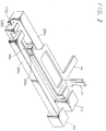
- FIG. 2 is a perspective view of an interlocking mechanism of a REC (recording) button and a recording operation slide member.
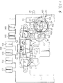
- FIG. 3 is an exploded perspective view illustrative of the recording and reproducing head, the erase head and main portions of an operation member that operates these heads and a transmission member.
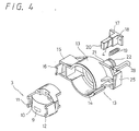
- FIG. 4 is an exploded perspective view illustrative of the recording and reproducing head and the erase head.
- the operation portion 200 includes a stop button 201, a pause button 202 for setting the cassette tape recorder in a pause mode, a fast forward (FF) button 203, a rewind (REW) button 204, a play (PLAY) button 205 and a recording (REC) button 206, in that order from right in FIG. 1 so that they can be freely depressed.
- the respective buttons 201 through 206 are adapted to set respective drive system in the driving state via operation levers (not shown).
- the respective operation buttons 201 through 206 are engaged with lock mechanism (not shown) so that they are locked in the depressed state when depressed.
- the operation lever of the stop button 201 is arranged so as not to be locked and is engaged with the above lock mechanism so as to release other operation levers from the locked state.
- the operation lever of the pause button 202 is not engaged with the lock mechanism at all and operated independently.
- the pause button 202 is engaged with a well-known push-push mechanism (not shown) disposed on the chassis 1 so that, when depressed once, the pause button 202 is locked in the depressed state thereby to temporarily pause the playback state, for example, and that, when depressed twice, the pause button 202 is released from the locked state thereby to return the cassette tape recorder to the playback state, for example.
- the operation levers of the FF button 203 and the REW button 204 selectively drive a positive-reverse switching mechanism of a high-speed transport system in the positive or opposite direction to thereby transport the tape at high speed in the positive or reverse direction.
- the lever of the PLAY button 205 selectively drives a positive and reverse switching mechanism of a tape transport system to thereby transport the tape at constant speed in the positive or reverse direction. Also, the lever of the PLAY button 205 actuates the head slider 2 so that the recording and reproducing head 3 or the like mounted on the head slider 2 is brought in contact with a predetermined surface of the tape. Further, the lever of the PLAY button 205 actuates a pair of capstans 5, 6 so that they are selectively brought in contact with a pair of capstans 7, 8, thereby the cassette tape recorder being set in the playback state in the positive or reverse direction.
- the recording and reproducing head 3 may reproduce (record) the tape during the tape is transported in the positive direction or in the reverse direction, i.e., during the tape is transported in the forward direction or in the backward direction, an azimuth angle thereof must be made accurate and the recording and reproducing head 3 is reversed by 180° in response to the tape transport direction so that it may come in contact with a corresponding track of the tape.
- a reverse mechanism of the recording and reproducing head 3 will be described in detail later.
- the operation lever of the REC button 206 actuates the recording system so that, when operated in combination with the PLAY button 205, the REC button 206 sets the cassette tape recorder in the recording state in any of the positive and reverse directions or sets the cassette tape recorder so that the cassette tape recorder can record the tape in the positive and reverse directions under the auto-reverse mode.
- the REC button 206 is depressed, the recording and reproducing head 3 and the erase head 4 of magnet type that is reversed together with the recording and reproducing head 3 are brought in contact with the corresponding tracks of the tape as will be described later on.
- FIG. 2 An interlocking mechanism of the REC button 206 and the PLAY button 205 is arranged as shown in FIG. 2.
- the REC button 206 has on an end portion of a lever 206a thereof an operation member 206b that is in contact with a contact member 205b formed on an end portion of a lever 205a of the PLAY button 205. Therefore, when the REC button 206 is depressed, the contact member 205b of the PLAY button 205 is pushed by the operation member 206b, whereby the PLAY button 205 is depressed together with the REC button 206.
- the REC button 206 has on its lever 206a a hook member 206c. The hook member 206c can be engaged with a hook portion 46a of a recording operation slide member 46, which will be described later on, when the REC button 206 is depressed.
- the recording and reproducing head 3 has a signal recording and reproducing head portion 9 shifted on one side of a tape contact surface 10. Tape guides 11, 12 are respectively formed on left and right side portions of the recording and reproducing head 3 along a tape travel direction.
- the recording and reproducing head 3 is fitted into a head supporting member 14 of a bottomed cylindrical configuration of the head holder 13.
- the head holder 13 has a second head supporting member 15 of a square shape integrally formed on one side portion thereof so as to accommodate therein the erase head 4.
- the second head supporting member 15 has a tape guide 16 formed on an outer top portion thereof.
- the erase head 4 in this embodiment is of the magnet type and projected under the condition that it is fitted into a holder 18 having a restricting plate 17 formed at the rear end thereof.
- the erase head 4 is inserted into the second head supporting member 15 so that it can be inserted into and ejected from the second head supporting member 15 from the rear side.
- the erase head 4 is urged toward the tape contact surface 10 side of the recording and reproducing head 3 under spring force of a spring member 19 extended between the inner end of the restricting plate 17 and the second head supporting member 15.
- the erase head 4 is spring-biased by the spring member 19 so that the restricting plate 17 is brought in contact with the rear end portion of the second head supporting member 15 and a tape contact surface 20 of the erase head 4 is substantially flush with the tape contact surface 10 of the recording and reproducing head 3.
- the recording and reproducing head 3 and the erase head 4 can be reversed in the range of 180° by the reverse mechanism. That is, the head holder 13 has on a rear surface center thereof a shaft body 21 that has on its top a gear shaft 22 protrusively provided.
- the gear shaft 22 is pivotally supported to a shaft 25 projected from a shaft supporting portion 24 of an attachment plate 23 erected from the head slider 2.
- the head holder 13 has on its rear surface portion opposite to the second head supporting member 15 a stopper member 26.
- the stopper member 26 can alternately come in contact with receiving members 27a, 27b that are formed on the head slider 2 at positions symmetrical to the shaft body 21, thereby reversing the head holder 13 in the range of 180°.
- the head holder 13 can be held at a predetermined position by selectively bringing the stopper member 26 of the head holder 13 in contact with the two receiving members 27a, 27b under spring force of a coil spring 30 extended between a pin lever 28 rearwardly projected from the shaft body 21 and a head gear base 29 which will be described later on.
- the head portion 9 of the recording and reproducing head 3 and the erase head 4 are in parallel to the tape travel direction.
- the head gear holder 29 is supported to the attachment plate 23 of the head slider 2.
- a sector wheel 32 is pivotally supported to a shaft portion 31 projected from the head gear holder 29.
- the sector wheel 32 has a tooth portion 33 that is meshed with the gear shaft 22 of the shaft body 21 of the head holder 13.
- the sector wheel 32 can be rotated about the shaft portion 31 by sliding a projected portion 34 formed on the lower end thereof by a cut-away portion 36 of a slider 35 that is slid in the directions shown by arrows a (normal direction) and b (reverse direction) in FIG. 3. Therefore, the head holder 13 can be reversed by means of the gear shaft 22 meshed with the gear portion 33.
- the slider 35 can be slid by a well-known drive mechanism which comprises a cam gear 37, a transmission gear 38 and a transmission mechanism, not shown.
- the cam gear 37 has on its circumferential portion a gear portion 37a.
- the gear portion 37a has on its part geneva-stop portions 37b, 37b of predetermined width at the symmetrical positions across a support shaft 39.
- the cam gear 37 has on its upper surface two protruded portions 40, 40 projected at the symmetrical positions across the supporting shaft 39.
- One end 42a of a spring member 42 supported to a shaft pin 41 erected from the chassis 1 is urged against one protruded portion 40.
- the other end 42b of the spring member 42 is urged against the lever 44 rotating about a shaft 43 serving as a fulcrum on the chassis 1.
- the transmission gear 37 and a transmission large-diameter gear 43 are pivotally and coaxially supported to the chassis 1 at the position corresponding to one geneva-stop portion 37b of the cam gear 37.
- the transmission large-diameter gear 43 is rotated by a rotation torque obtained from a pulley rotated by a motor serving as a drive source (not shown).
- the head slider 2 has on a rear surface thereof a recording operation slide member 46 that is slid in the tape travel direction when the REC button 206 is depressed.
- a pair of left and right engagement members 47 are erected from the recording operation slide member 46 to the left and right of the head holder 13.
- FIG. 1 shows the condition that the cassette tape recorder is in the stop condition when the tape is transported in the normal condition.
- the PLAY button 205 is depressed in order to realize the playback mode as shown in FIG. 5, then the recording and reproducing head 3 is moved to a front tape surface side of a cassette C shown by a phantom line together with the slider head 2 that is slid in unison with the PLAY button 205.
- the restricting plate 17 of the erase head 4 supported on the head holder 13 that is moved together with the recording and reproducing head 3 comes in contact with the engagement members 47 erected on the recording operation slide member 46.
- the recording and reproducing head 3 is moved together with the head holder 13 when the restricting plate 17 and the engagement members 47 are brought in contact with one another, the erase head 4 is inhibited from being moved. Hence, the so-called erase head 4 is substantially moved backwardly from the head holder 13. Therefore, in the playback mode under the normal condition in which the tape T is transported in the positive direction, only the recording and reproducing head 3 is brought in contact with the tape surface located at the front surface of the cassette C shown by a phantom line and the cassette tape recorder is set in the tape loading state under the playback mode. Therefore, the tape T that is being transported under normal condition is not in contact with the erase head 4 as shown in FIG. 8A and is brought in contact with only the tape contact surface 10 of the recording and reproducing head 3. Hence, the tape T is transported in the positive direction (i.e., traveled in the forward direction).
- the transmission gear 38 is rotated by a rotation torque from a tape drive motor (not shown) via the transmission large-diameter gear 43.
- the geneva-stop portion 37b of the cam gear 37 is opposed to the transmission gear 38. Consequently, the cam gear 37 is not meshed with the transmission gear 38 and is stopped.
- the locked state between the lever 44 and the cam gear 37 is released by moving the manual operation lever 45 in the arrow c direction in FIG. 5, whereby the cam gear 37 is rotated by a predetermined amount in the arrow d direction under spring force of the one end 42a of the spring member 42.
- the gear portion 37a of the cam gear 37 is meshed with the rotating transmission gear 38, whereby the cam gear 37 is rotated in the arrow d direction in FIG. 5.
- the recording and reproducing head 3 and the pinch rollers 6, 7 are moved backwardly together with the head holder 13 through an interlocking member (not shown) in a ganged relation therewith and then spaced from the tape surface.
- the slider 35 is slid in the direction shown by an arrow e in FIG. 7 through a transmission mechanism (not shown) thereby to push the projected portion 34 of the sector wheel 32 engaged with the recessed portion 36.
- the sector wheel 32 is rotated about the shaft portion 31 to rotate the head holder 13 and the recording and reproducing head 3 about the shaft 25 in the direction shown by an arrow f in FIG.
- the recording and reproducing head 3 and the pinch rollers 6, 7 are moved to the surface side of the tape T that is in the positive direction operation (reverse) state and then set in the tape loading state. Therefore, the tape T, which is in the reverse transport state, is transported in the reverse direction while it is not in contact with the erase head 4 but is brought in contact with only the tape contact surface 10 of the recording and reproducing head 3 as shown in FIG. 8B.
- the play button 205 is depressed together with the REC button 206 in order to set the cassette tape recorder in the recording mode as shown in FIG. 6 under the condition that the cassette tape recorder shown in FIG. 1 is stopped in the normal condition, then the hook member 206c formed on the lever 206a of the REC button 206 is brought in contact with the hook portion 46a of the recording operation slide member 46 and then pulled back, whereby the recording operation slide member 46 is slid together with the head slider 2.
- the erase head 4 supported on the head holder 13 is not brought in contact with the engagement member 47 and moved to the tape surface side of the front surface of the tape cassette C shown by the phantom line.
- the cassette tape recorder is set in the loading state upon recording mode. Therefore, the tape T that is in the normal transport state is brought in contact with the tape contact surface 20 of the erase head 4 and then comes in contact with the tape contact surface 10 of the recording and reproducing head 3 sequentially, thereby being transported in the positive direction as shown in FIG. 9A.
- the tape T is transported in the positive direction under the normal condition upon recording.
- the auto-reverse mechanism (not shown) is actuated.
- the recording and reproducing head 3 and the erase head 4 are reversed similarly to the reproducing mode by the operation of the manual operation lever 45.
- the tape T that was set in the reverse transport state is brought in contact with the tape contact surface 10 of the recording and reproducing head 3 sequentially and transported in the reverse direction.
- the recording mode and the reproducing mode in the tape normal transport state and the reverse transport state can be effected by using one erase head 4.
- the erase head 4 is made retractable such that it is brought in contact with the tape surface in the recording mode and is inhibited from being brought in contact with the tape surface upon reproduction. The number of the erase head 4 can be minimized and the manufacturing cost of the cassette tape recorder can be reduced.
- one erase head 4 can be utilized in both the tape normal transport state and the reverse transport state, the erase characteristics that the erase head 4 presents when the tape T is transported in the positive direction and in the reverse direction become the same. Also, the number of tape guides can be minimized and the adjustment of tape path becomes easy.
- the present invention is not limited thereto and the sector wheel 32 may be rotated by a plunger, for example.
- the present invention is not limited thereto and the recording head and the reproducing head may be formed separately.
- cassette tape recorder is utilized as the recording and reproducing apparatus as described above, the present invention is not limited thereto and may be applied to a wide variety of recording and reproducing apparatus.
- the erase head that is moved in the positive and reverse directions between two positions at which the tape is transported at constant speed in the positive and reverse directions can be constructed so as to be moved backwardly from the recording and reproducing head or the recording head and the reproducing head. Therefore, the number of erase heads can be minimized and the recording and reproducing apparatus can be made inexpensive.
- one erase head can be utilized in both the tape normal transport state and the reverse transport state, the erase characteristics that the erase head presents when the tape is transported in the positive direction and in the reverse direction become the same. Furthermore, the number of tape guides can be minimized and hence the adjustment of tape path becomes easy.
Landscapes
- Adjustment Of The Magnetic Head Position Track Following On Tapes (AREA)
- Recording Or Reproducing By Magnetic Means (AREA)
Abstract
Description
- The present invention generally relates to recording and reproducing apparatus and, more particularly, to a recording and reproducing apparatus having an auto-reverse function in which a recording and reproducing head and an erase head are both of reversible types.
- One conventional recording and reproducing apparatus that can record or reproduce a tape during the tape is transported in the positive and reverse directions is generally referred to as an auto-reverse recording and reproducing apparatus. According to the auto-reverse function, the tape can be automatically recorded or reproduced during the tape is transported in the positive direction while the tape loading state and the operation unit setting condition need not be changed at all when the tape reaches its end. Also, during the tape is transported in the reverse direction, the tape can be recorded or reproduced automatically. Therefore, the auto-reverse function is useful particularly when a recording or reproduction of a long time is required.
- As a recording and reproducing apparatus having the above auto-reverse function, there is known a so-called combination head in which a recording and reproducing head and an erase head are constructed integrally. Japanese published utility model publication No. 63-31213 describes this type of head in which the erase head is reversed by 180° together with the recording and reproducing head in order to switch the erasing direction.
- Another conventional auto-reverse recording and reproducing apparatus utilizes a four-channel recording and reproducing head whose erase heads are opposed to small windows of a cassette half.
- The former recording and reproducing apparatus employs the erase head of a coil-type head utilizing an AC bias. Such coil-type erase head is expensive and the erase head must be disposed in a limited small space. Therefore, if the tape is curled at the guide portion when a tape path of head is adjusted, then the state that the tape is in contact with the erase head is affected. There is then the problem that the tape is not erased completely. The latter recording and reproducing apparatus needs two erase heads and therefore becomes expensive. Also, because characteristics of the two erase heads are not the same, erasing characteristics that the two erase heads present during the tape is transported in the positive direction and in the reverse direction are fluctuated. Furthermore, the number of tape guides is increased as the number of erase heads is increased. There is then the problem that adjustment of tape path becomes troublesome.
- Therefore, it is an object of the present invention to provide an improved recording and reproducing apparatus in which the aforesaid shortcomings and disadvantages encountered with the prior art can be eliminated.
- More specifically, it is an object of the present invention to provide a recording and reproducing apparatus in which a tape can be recorded and reproduced both in the positive and reverse direction by utilizing a single erase head.
- It is another object of the present invention to provide a recording and reproducing apparatus in which erase characteristics that an erase head presents when a tape is transported in the positive direction and in the reverse direction can be prevented from being fluctuated.
- It is a further object of the present invention to provide a recording and reproducing apparatus in which the number of erase heads can be minimized.
- It is still a further object of the present invention to provide a recording and reproducing apparatus in which the number of tape guides can be minimized.
- It is still a further object of the present invention to provide a recording and reproducing apparatus in which a tape path can be adjusted with ease.
- It is yet a further object of the present invention to provide a recording and reproducing apparatus which can be produced inexpensively.
- According to a first aspect of the present invention, there is provided a recording and reproducing apparatus which comprises a positive and reverse switching member for switching a travel of a tape so that the tape is transported at a constant speed in the positive direction or in the reverse direction, a head slider sliding between a recordable or reproducible first position at which a recording and reproducing head and an erase head are brought in contact with the tape and a second position at which the recording and reproducing head and the erase head are moved away from the tape in a ganged relation with a switching operation of the positive and reverse switching member, a head supporting member supported on the head slider for supporting the recording and reproducing head and the erase head so that tape contact surfaces of the recording and reproducing head and the erase head are projected, and a reverse member for reversing the head supporting member in a ganged relation with the switching operation of the positive and reverse switching means under the condition that the tape contact surfaces of the recording and reproducing head and the erase head are spaced from the tape in an opposing fashion so that the recording and reproducing head and the erase head are reversed at two positions corresponding to the positions at which the tape is transported at a constant speed in the positive direction and in the reverse direction, wherein the erase head is supported by the head supporting member so that the erase head can be moved in the direction in which it is moved away from the tape.
- In accordance with a second aspect of the present invention, there is provided a recording and reproducing apparatus which comprises a positive and reverse switching member for switching a travel of a tape so that the tape is transported at a constant speed in the positive direction or in the reverse direction, a head slider sliding between a recordable or reproducible first position and a second position which is away from the tape, a head supporting member supported on the head slider for supporting a recording and reproducing head and an erase head so that tape contact surfaces of the recording and reproducing head and the erase head are projected, and a reverse member for reversing the head supporting member in a ganged relation with the switching operation of the positive and reverse switching member under the condition that the tape contact surfaces of the recording and reproducing head and the erase head are spaced from said tape in an opposing fashion so that the recording and reproducing head and the erase head are reversed at two positions corresponding to the positions at which the tape is transported at a constant speed in the positive direction and in the reverse direction, and a recording operation slide member which can be slid only when a recording mode is set, wherein the head supporting member supports the erase head so that the erase head can be moved away from the tape and the recording operation slide member holds the erase head at the position distant from the tape when the head slider is set in a reproducing mode and moved to the recordable or reproducible first position.
- The above and other objects, features, and advantages of the present invention will become apparent from the following detailed description of an illustrative embodiment thereof to be read in conjunction with the accompanying drawings, in which like reference numerals are used to identify the same or similar parts in the several views.
-
- FIG. 1 is a plan view illustrative of a main portion of a cassette tape recorder according to an embodiment of the present invention;
- FIG. 2 is a perspective view illustrative of a REC (recording) button, a PLAY (play) button and a recording operation slide member;
- FIG. 3 is an exploded perspective view of a main portion of the cassette tape recorder according to the embodiment of the present invention;
- FIG. 4 is an exploded perspective view of a recording and reproducing head and an erase head;
- FIG. 5 is a plan view illustrative of a main portion of the recording and reproducing apparatus upon playback;
- FIG. 6 is a plan view illustrative of a main portion of the recording and reproducing apparatus upon recording;
- FIG. 7 is a rear view illustrative of the condition that a head holder and a sector wheel are meshed with each other;
- FIGS. 8A and 8B are respectively enlarged plan views illustrative of a main portion of the cassette tape recorder when a tape is transported in the normal state and the reverse state upon playback; and
- FIGS. 9A and 9B are respectively enlarged plan views illustrative of a main portion of the cassette tape recorder when the tape is transported in the normal state and the reverse state upon recording.
-
- A recording and reproducing apparatus according to an embodiment of the present invention will hereinafter be described with reference to the drawings.
- FIG. 1 of the accompanying drawings is a plan view of a recording and reproducing head and an erase head of an auto-reverse cassette tape recorder. FIG. 2 is a perspective view of an interlocking mechanism of a REC (recording) button and a recording operation slide member. FIG. 3 is an exploded perspective view illustrative of the recording and reproducing head, the erase head and main portions of an operation member that operates these heads and a transmission member. FIG. 4 is an exploded perspective view illustrative of the recording and reproducing head and the erase head.
- As shown in FIGS. 1, 3 and 4, there is provided a
chassis 1 of a cassette tape recorder. Anoperation portion 200 is outwardly projected from thechassis 1 as shown in FIG. 1. Theoperation portion 200 includes astop button 201, apause button 202 for setting the cassette tape recorder in a pause mode, a fast forward (FF)button 203, a rewind (REW)button 204, a play (PLAY)button 205 and a recording (REC)button 206, in that order from right in FIG. 1 so that they can be freely depressed. Therespective buttons 201 through 206 are adapted to set respective drive system in the driving state via operation levers (not shown). - The
respective operation buttons 201 through 206 are engaged with lock mechanism (not shown) so that they are locked in the depressed state when depressed. The operation lever of thestop button 201 is arranged so as not to be locked and is engaged with the above lock mechanism so as to release other operation levers from the locked state. - The operation lever of the
pause button 202 is not engaged with the lock mechanism at all and operated independently. Thepause button 202 is engaged with a well-known push-push mechanism (not shown) disposed on thechassis 1 so that, when depressed once, thepause button 202 is locked in the depressed state thereby to temporarily pause the playback state, for example, and that, when depressed twice, thepause button 202 is released from the locked state thereby to return the cassette tape recorder to the playback state, for example. - The operation levers of the
FF button 203 and theREW button 204 selectively drive a positive-reverse switching mechanism of a high-speed transport system in the positive or opposite direction to thereby transport the tape at high speed in the positive or reverse direction. - The lever of the
PLAY button 205 selectively drives a positive and reverse switching mechanism of a tape transport system to thereby transport the tape at constant speed in the positive or reverse direction. Also, the lever of thePLAY button 205 actuates thehead slider 2 so that the recording and reproducinghead 3 or the like mounted on thehead slider 2 is brought in contact with a predetermined surface of the tape. Further, the lever of thePLAY button 205 actuates a pair ofcapstans capstans - In order that the recording and reproducing
head 3 may reproduce (record) the tape during the tape is transported in the positive direction or in the reverse direction, i.e., during the tape is transported in the forward direction or in the backward direction, an azimuth angle thereof must be made accurate and the recording and reproducinghead 3 is reversed by 180° in response to the tape transport direction so that it may come in contact with a corresponding track of the tape. A reverse mechanism of the recording and reproducinghead 3 will be described in detail later. - The operation lever of the
REC button 206 actuates the recording system so that, when operated in combination with thePLAY button 205, theREC button 206 sets the cassette tape recorder in the recording state in any of the positive and reverse directions or sets the cassette tape recorder so that the cassette tape recorder can record the tape in the positive and reverse directions under the auto-reverse mode. When theREC button 206 is depressed, the recording and reproducinghead 3 and theerase head 4 of magnet type that is reversed together with the recording and reproducinghead 3 are brought in contact with the corresponding tracks of the tape as will be described later on. - An interlocking mechanism of the
REC button 206 and thePLAY button 205 is arranged as shown in FIG. 2. As shown in FIG. 2, theREC button 206 has on an end portion of alever 206a thereof anoperation member 206b that is in contact with acontact member 205b formed on an end portion of alever 205a of thePLAY button 205. Therefore, when theREC button 206 is depressed, thecontact member 205b of thePLAY button 205 is pushed by theoperation member 206b, whereby thePLAY button 205 is depressed together with theREC button 206. TheREC button 206 has on itslever 206a ahook member 206c. Thehook member 206c can be engaged with ahook portion 46a of a recordingoperation slide member 46, which will be described later on, when theREC button 206 is depressed. - Arrangements of the recording and reproducing
head 3 and the erasehead 4 and the reverse mechanism thereof will be described next. - As shown in FIGS. 3 and 4, the recording and reproducing
head 3 has a signal recording and reproducinghead portion 9 shifted on one side of atape contact surface 10. Tape guides 11, 12 are respectively formed on left and right side portions of the recording and reproducinghead 3 along a tape travel direction. The recording and reproducinghead 3 is fitted into ahead supporting member 14 of a bottomed cylindrical configuration of thehead holder 13. - The
head holder 13 has a secondhead supporting member 15 of a square shape integrally formed on one side portion thereof so as to accommodate therein the erasehead 4. The secondhead supporting member 15 has atape guide 16 formed on an outer top portion thereof. The erasehead 4 in this embodiment is of the magnet type and projected under the condition that it is fitted into aholder 18 having a restrictingplate 17 formed at the rear end thereof. The erasehead 4 is inserted into the secondhead supporting member 15 so that it can be inserted into and ejected from the secondhead supporting member 15 from the rear side. The erasehead 4 is urged toward thetape contact surface 10 side of the recording and reproducinghead 3 under spring force of aspring member 19 extended between the inner end of the restrictingplate 17 and the secondhead supporting member 15. More specifically, the erasehead 4 is spring-biased by thespring member 19 so that the restrictingplate 17 is brought in contact with the rear end portion of the secondhead supporting member 15 and atape contact surface 20 of the erasehead 4 is substantially flush with thetape contact surface 10 of the recording and reproducinghead 3. - The recording and reproducing
head 3 and the erasehead 4 can be reversed in the range of 180° by the reverse mechanism. That is, thehead holder 13 has on a rear surface center thereof ashaft body 21 that has on its top agear shaft 22 protrusively provided. Thegear shaft 22 is pivotally supported to ashaft 25 projected from ashaft supporting portion 24 of anattachment plate 23 erected from thehead slider 2. - The
head holder 13 has on its rear surface portion opposite to the second head supporting member 15 astopper member 26. Thestopper member 26 can alternately come in contact with receivingmembers head slider 2 at positions symmetrical to theshaft body 21, thereby reversing thehead holder 13 in the range of 180°. Thehead holder 13 can be held at a predetermined position by selectively bringing thestopper member 26 of thehead holder 13 in contact with the two receivingmembers coil spring 30 extended between apin lever 28 rearwardly projected from theshaft body 21 and ahead gear base 29 which will be described later on. When thehead holder 13 is held at the stop position, thehead portion 9 of the recording and reproducinghead 3 and the erasehead 4 are in parallel to the tape travel direction. - The
head gear holder 29 is supported to theattachment plate 23 of thehead slider 2. Asector wheel 32 is pivotally supported to ashaft portion 31 projected from thehead gear holder 29. Thesector wheel 32 has atooth portion 33 that is meshed with thegear shaft 22 of theshaft body 21 of thehead holder 13. Thesector wheel 32 can be rotated about theshaft portion 31 by sliding a projectedportion 34 formed on the lower end thereof by a cut-awayportion 36 of aslider 35 that is slid in the directions shown by arrows a (normal direction) and b (reverse direction) in FIG. 3. Therefore, thehead holder 13 can be reversed by means of thegear shaft 22 meshed with thegear portion 33. - The
slider 35 can be slid by a well-known drive mechanism which comprises acam gear 37, atransmission gear 38 and a transmission mechanism, not shown. A main arrangement of the drive mechanism will be described. Thecam gear 37 has on its circumferential portion agear portion 37a. Thegear portion 37a has on its part geneva-stop portions support shaft 39. Thecam gear 37 has on its upper surface two protrudedportions shaft 39. Oneend 42a of aspring member 42 supported to ashaft pin 41 erected from thechassis 1 is urged against one protrudedportion 40. Theother end 42b of thespring member 42 is urged against thelever 44 rotating about ashaft 43 serving as a fulcrum on thechassis 1. - While the
cam gear 37 is urged to rotate in the arrow d direction in FIG. 1 under spring force of thespring member 42, thecam gear 37 is engaged with thelever 44 and locked. Thelever 44 is released from being locked to thecam gear 37 by moving amanual operation lever 45 in the arrow c direction in FIG. 5 so that thecam gear 37 is rotated by a predetermined amount in the arrow d direction in FIG. 5 under spring force of thespring member 42. - The
transmission gear 37 and a transmission large-diameter gear 43 are pivotally and coaxially supported to thechassis 1 at the position corresponding to one geneva-stop portion 37b of thecam gear 37. The transmission large-diameter gear 43 is rotated by a rotation torque obtained from a pulley rotated by a motor serving as a drive source (not shown). - The
head slider 2 has on a rear surface thereof a recordingoperation slide member 46 that is slid in the tape travel direction when theREC button 206 is depressed. A pair of left andright engagement members 47 are erected from the recordingoperation slide member 46 to the left and right of thehead holder 13. - Operation of the cassette tape recorder thus arranged according to this embodiment will be described.
- FIG. 1 shows the condition that the cassette tape recorder is in the stop condition when the tape is transported in the normal condition. Under this normal condition, if the
PLAY button 205 is depressed in order to realize the playback mode as shown in FIG. 5, then the recording and reproducinghead 3 is moved to a front tape surface side of a cassette C shown by a phantom line together with theslider head 2 that is slid in unison with thePLAY button 205. On the other hand, since the recordingoperation slide member 46 is not moved in unison with thePLAY button 205 and is stopped, the restrictingplate 17 of the erasehead 4 supported on thehead holder 13 that is moved together with the recording and reproducinghead 3 comes in contact with theengagement members 47 erected on the recordingoperation slide member 46. Although the recording and reproducinghead 3 is moved together with thehead holder 13 when the restrictingplate 17 and theengagement members 47 are brought in contact with one another, the erasehead 4 is inhibited from being moved. Hence, the so-called erasehead 4 is substantially moved backwardly from thehead holder 13. Therefore, in the playback mode under the normal condition in which the tape T is transported in the positive direction, only the recording and reproducinghead 3 is brought in contact with the tape surface located at the front surface of the cassette C shown by a phantom line and the cassette tape recorder is set in the tape loading state under the playback mode. Therefore, the tape T that is being transported under normal condition is not in contact with the erasehead 4 as shown in FIG. 8A and is brought in contact with only thetape contact surface 10 of the recording and reproducinghead 3. Hence, the tape T is transported in the positive direction (i.e., traveled in the forward direction). - When the tape T under the normal condition is reproduced in the positive direction and the tape T is reversed from the position direction to the opposite direction, an auto-reverse mechanism (not shown) is actuated. In this embodiment, a description will b made on the case that the running tape is arbitrarily reversed by the manual operation shown in FIG. 1.
- During the tape that was set in the normal condition is reproduced, the
transmission gear 38 is rotated by a rotation torque from a tape drive motor (not shown) via the transmission large-diameter gear 43. At that time, the geneva-stop portion 37b of thecam gear 37 is opposed to thetransmission gear 38. Consequently, thecam gear 37 is not meshed with thetransmission gear 38 and is stopped. When the tape travel direction is reversed during the tape travels, the locked state between thelever 44 and thecam gear 37 is released by moving themanual operation lever 45 in the arrow c direction in FIG. 5, whereby thecam gear 37 is rotated by a predetermined amount in the arrow d direction under spring force of the oneend 42a of thespring member 42. Then, thegear portion 37a of thecam gear 37 is meshed with therotating transmission gear 38, whereby thecam gear 37 is rotated in the arrow d direction in FIG. 5. - When the rotation of the
cam gear 37 is started, the recording and reproducinghead 3 and thepinch rollers head holder 13 through an interlocking member (not shown) in a ganged relation therewith and then spaced from the tape surface. Simultaneously, theslider 35 is slid in the direction shown by an arrow e in FIG. 7 through a transmission mechanism (not shown) thereby to push the projectedportion 34 of thesector wheel 32 engaged with the recessedportion 36. As a result, thesector wheel 32 is rotated about theshaft portion 31 to rotate thehead holder 13 and the recording and reproducinghead 3 about theshaft 25 in the direction shown by an arrow f in FIG. 7 through thegear portion 22 provided on thehead holder 13 meshed with thegear portion 33, whereby thestopper member 26 of thehead holder 13 is brought in contact with the receivingmember 27b of thehead slider 2 and then stopped. That is, the recording and reproducinghead 3 are reversed together with thehead holder 3 by 180°. - Substantially concurrently with the reverse operation of the recording and reproducing
head 3, the recording and reproducinghead 3 and thepinch rollers head 4 but is brought in contact with only thetape contact surface 10 of the recording and reproducinghead 3 as shown in FIG. 8B. - If the
play button 205 is depressed together with theREC button 206 in order to set the cassette tape recorder in the recording mode as shown in FIG. 6 under the condition that the cassette tape recorder shown in FIG. 1 is stopped in the normal condition, then thehook member 206c formed on thelever 206a of theREC button 206 is brought in contact with thehook portion 46a of the recordingoperation slide member 46 and then pulled back, whereby the recordingoperation slide member 46 is slid together with thehead slider 2. More specifically, since thehead holder 13 supported on thehead slider 2 and the recording and reproducinghead 3 are moved and theengagement member 47 vertically provided on the recording and reproducinghead 3 also is moved, the erasehead 4 supported on thehead holder 13 is not brought in contact with theengagement member 47 and moved to the tape surface side of the front surface of the tape cassette C shown by the phantom line. Thus, the cassette tape recorder is set in the loading state upon recording mode. Therefore, the tape T that is in the normal transport state is brought in contact with thetape contact surface 20 of the erasehead 4 and then comes in contact with thetape contact surface 10 of the recording and reproducinghead 3 sequentially, thereby being transported in the positive direction as shown in FIG. 9A. - Then, the tape T is transported in the positive direction under the normal condition upon recording. When the tape T is reversed from the positive direction to the reverse direction, the auto-reverse mechanism (not shown) is actuated. Also in this case, as shown in FIG. 9B, the recording and reproducing
head 3 and the erasehead 4 are reversed similarly to the reproducing mode by the operation of themanual operation lever 45. As a result, the tape T that was set in the reverse transport state is brought in contact with thetape contact surface 10 of the recording and reproducinghead 3 sequentially and transported in the reverse direction. - As described above, according to the cassette tape recorder of this embodiment, the recording mode and the reproducing mode in the tape normal transport state and the reverse transport state can be effected by using one erase
head 4. In addition, the erasehead 4 is made retractable such that it is brought in contact with the tape surface in the recording mode and is inhibited from being brought in contact with the tape surface upon reproduction. The number of the erasehead 4 can be minimized and the manufacturing cost of the cassette tape recorder can be reduced. - Further, since one erase
head 4 can be utilized in both the tape normal transport state and the reverse transport state, the erase characteristics that the erasehead 4 presents when the tape T is transported in the positive direction and in the reverse direction become the same. Also, the number of tape guides can be minimized and the adjustment of tape path becomes easy. - While the
sector wheel 32 is rotated by the slide operation of theslider 35 as the reverse mechanism of the recording and reproducinghead 3 and the erasehead 4 as described above, the present invention is not limited thereto and thesector wheel 32 may be rotated by a plunger, for example. - Further, while the recording and reproducing head in which the recording head and the reproducing head are formed integrally is utilized as described above, the present invention is not limited thereto and the recording head and the reproducing head may be formed separately.
- Furthermore, while the cassette tape recorder is utilized as the recording and reproducing apparatus as described above, the present invention is not limited thereto and may be applied to a wide variety of recording and reproducing apparatus.
- As set out above, according to the recording and reproducing apparatus of the present invention, the erase head that is moved in the positive and reverse directions between two positions at which the tape is transported at constant speed in the positive and reverse directions can be constructed so as to be moved backwardly from the recording and reproducing head or the recording head and the reproducing head. Therefore, the number of erase heads can be minimized and the recording and reproducing apparatus can be made inexpensive.
- Further, since one erase head can be utilized in both the tape normal transport state and the reverse transport state, the erase characteristics that the erase head presents when the tape is transported in the positive direction and in the reverse direction become the same. Furthermore, the number of tape guides can be minimized and hence the adjustment of tape path becomes easy.
- Having described a preferred embodiment of the invention with reference to the accompanying drawings, it is to be understood that the invention is not limited to that precise embodiment and that various changes and modifications could be effected by one skilled in the art without departing from the spirit or scope of the invention as defined in the appended claims.
Claims (9)
- A recording and reproducing apparatus comprising:(a) positive and reverse switching means for switching a travel of a tape so that said tape is transported at a constant speed in the positive direction or in the reverse direction;(b) a head slider sliding between a recordable or reproducible first position at which a recording and reproducing head and an erase head are brought in contact with said tape and a second position at which said recording and reproducing head and said erase head are moved away from said tape in a ganged relation with a switching operation of said positive and reverse switching means;(c) a head supporting member supported on said head slider for supporting said recording and reproducing head and said erase head so that tape contact surfaces of said recording and reproducing head and said erase head are projected; and(d) reverse means for reversing said head supporting member in a ganged relation with the switching operation of said positive and reverse switching means under the condition that the tape contact surfaces of said recording and reproducing head and said erase head are spaced from said tape in an opposing fashion so that said recording and reproducing head and said erase head are reversed at two positions corresponding to the positions at which said tape is transported at a constant speed in the positive direction and in the reverse direction, wherein said erase is supported by said head supporting member so that said erase head can be moved in the direction in which it is moved away from said tape.
- The recording and reproducing apparatus according to claim 1, further comprising spring-biasing means for spring-biasing said erase head, which is slidably held by said head supporting member, in the direction in which the tape contact surface thereof is projected and a restricting mechanism for restricting a projecting position of said erase head.
- The recording and reproducing apparatus according to claim 1, further comprising a recording operation slide member formed of a member different from that of said head slider and which can be slid only when said recording and reproducing apparatus is set in recording operation mode and an engagement member erected on said recording operation slide member, wherein said engagement member of said recording operation slide member comes in contact with said erase head in a reproducing operation mode to thereby substantially move said erase head back from said recording and reproducing head.
- The recording and reproducing apparatus according to claim 3, wherein said erase head is made of a magnet.
- A recording and reproducing apparatus comprising:(a) positive and reverse switching means for switching a travel of a tape so that said tape is transported at a constant speed in the positive directicn or in the reverse direction;(b) a head slider sliding between a recordable or reproducible first position and a second position which is away from said tape;(c) a head supporting member supported on said head slider for supporting a recording and reproducing head and an erase head so that tape contact surfaces of said recording and reproducing head and said erase head are projected; and(d) reverse means for reversing said head supporting member in a ganged relation with the switching operation of said positive and reverse switching means under the condition that the tape contact surfaces of said recording and reproducing head and said erase head are spaced from said tape in an opposing fashion so that said recording and reproducing head and said erase head are reversed at two positions corresponding to the positions at which said tape is transported at a constant speed in the positive direction and in the reverse direction; and(e) a recording operation slide member which can be slid only when a recording mode is set, wherein said head supporting member supports said erase head so that said erase head can be moved away from said tape and said recording operation slide member holds said erase head at the position distant from said tape when said head slider is set in a reproducing mode and moved to said recordable or reproducible first position.
- The recording and reproducing apparatus according to claim 5, wherein said head slider is moved from said recordable or reproducible first position to said second position distant from said tape in a ganged relation with a switching operation of said positive and reverse switching means when said head slider is set in said recording or reproducing mode in which said head slider is set at said recordable or reproducible first position.
- The recording and reproducing apparatus according to claim 5, further comprising spring-biasing means for spring-biasing said erase head, which is slidably held by said head supporting member, in the direction in which the tape contact surface thereof is projected and a restricting mechanism for restricting a projecting position of said erase head.
- The recording and reproducing apparatus according to claim 7, wherein said erase head is made of a magnet.
- The recording and reproducing apparatus according to claim 5, wherein said recording and reproducing head comprises a recording head and a reproducing head which are formed separately.
Applications Claiming Priority (2)
| Application Number | Priority Date | Filing Date | Title |
|---|---|---|---|
| JP152795/92 | 1992-05-20 | ||
| JP04152795A JP3094662B2 (en) | 1992-05-20 | 1992-05-20 | Recording and playback device |
Publications (2)
| Publication Number | Publication Date |
|---|---|
| EP0571200A1 true EP0571200A1 (en) | 1993-11-24 |
| EP0571200B1 EP0571200B1 (en) | 1998-11-11 |
Family
ID=15548317
Family Applications (1)
| Application Number | Title | Priority Date | Filing Date |
|---|---|---|---|
| EP93303889A Expired - Lifetime EP0571200B1 (en) | 1992-05-20 | 1993-05-19 | Recording and reproducing head apparatus for a tape player |
Country Status (5)
| Country | Link |
|---|---|
| US (1) | US5481424A (en) |
| EP (1) | EP0571200B1 (en) |
| JP (1) | JP3094662B2 (en) |
| KR (1) | KR100301447B1 (en) |
| DE (1) | DE69321992T2 (en) |
Families Citing this family (5)
| Publication number | Priority date | Publication date | Assignee | Title |
|---|---|---|---|---|
| US6333838B1 (en) | 1998-06-22 | 2001-12-25 | Hewlett-Packard Co. | Voice coil actuated carriage in which a support structure for the carriage is disposed at least partially within the motor |
| US6411474B1 (en) * | 1998-06-22 | 2002-06-25 | Hewlett-Packard Co. | Carriage and actuator assembly |
| US6388836B2 (en) | 1998-11-13 | 2002-05-14 | Hewlett-Packard Company | Magnetic shield for a tape drive read/write head |
| JP4717791B2 (en) * | 2006-12-04 | 2011-07-06 | パイオニア株式会社 | Disk transport device, disk device, and disk transport method |
| US9119716B2 (en) | 2011-07-27 | 2015-09-01 | Edwards Lifesciences Corporation | Delivery systems for prosthetic heart valve |
Family Cites Families (14)
| Publication number | Priority date | Publication date | Assignee | Title |
|---|---|---|---|---|
| US3800327A (en) * | 1971-07-10 | 1974-03-26 | Sony Corp | Magnetic recording and reproducing apparatus with erasing head and a tape guide mounted on a movable carriage |
| JPS6029079Y2 (en) * | 1978-05-08 | 1985-09-03 | ソニー株式会社 | Cassette ejection prevention device for cassette type recording/playback equipment |
| JPS634260Y2 (en) * | 1978-11-16 | 1988-02-03 | ||
| JPS57198563A (en) * | 1981-05-29 | 1982-12-06 | Toshiba Corp | Cassette tape recorder |
| JPS5891556A (en) * | 1981-11-25 | 1983-05-31 | Toshiba Corp | Auto reverse device of tape recorder |
| JPS58212645A (en) * | 1982-06-04 | 1983-12-10 | Toshiba Corp | Tape recorder device |
| JPS59175016A (en) * | 1983-03-22 | 1984-10-03 | Tanashin Denki Co | Magnetic head inverter |
| JPS59213049A (en) * | 1983-05-18 | 1984-12-01 | Victor Co Of Japan Ltd | Driving device of inversion type tape recorder |
| JPS6122414A (en) * | 1984-07-09 | 1986-01-31 | Matsushita Electric Ind Co Ltd | Tape recorder |
| JPS6122413A (en) * | 1984-07-09 | 1986-01-31 | Matsushita Electric Ind Co Ltd | Tape recorder |
| JPS60115019A (en) * | 1984-10-31 | 1985-06-21 | Toshiba Corp | Cassette tape recorder |
| JPS60150224A (en) * | 1984-12-11 | 1985-08-07 | Toshiba Corp | Head device of tape recorder |
| JPH01232512A (en) * | 1988-03-10 | 1989-09-18 | Alps Electric Co Ltd | Automatic reversing magnetic head and mode switching device for automatic reversing tape player using automatic reversing magnetic head |
| JPH0648565Y2 (en) * | 1988-07-20 | 1994-12-12 | タナシン電機株式会社 | Reverse tape recorder |
-
1992
- 1992-05-20 JP JP04152795A patent/JP3094662B2/en not_active Expired - Fee Related
-
1993
- 1993-04-24 KR KR1019930006929A patent/KR100301447B1/en not_active IP Right Cessation
- 1993-05-19 EP EP93303889A patent/EP0571200B1/en not_active Expired - Lifetime
- 1993-05-19 DE DE69321992T patent/DE69321992T2/en not_active Expired - Fee Related
-
1994
- 1994-08-30 US US08/298,373 patent/US5481424A/en not_active Expired - Lifetime
Non-Patent Citations (3)
| Title |
|---|
| PATENT ABSTRACTS OF JAPAN vol. 9, no. 269 (P-400)(1992) 26 October 1985 & JP-A-60 115 019 ( TOSHIBA ) 21 June 1985 * |
| PATENT ABSTRACTS OF JAPAN vol. 9, no. 323 (P-414)18 December 1985 & JP-A-60 150 224 ( TOSHIBA ) 7 August 1985 * |
| PATENT ABSTRACTS OF JAPAN vol. 9, no. 33 (P-334)(1756) 13 February 1985 & JP-A-59 175 016 ( TANASHIN DENKI K.K. ) 3 October 1984 * |
Also Published As
| Publication number | Publication date |
|---|---|
| KR100301447B1 (en) | 2001-10-22 |
| KR930023963A (en) | 1993-12-21 |
| DE69321992D1 (en) | 1998-12-17 |
| JPH05325158A (en) | 1993-12-10 |
| EP0571200B1 (en) | 1998-11-11 |
| JP3094662B2 (en) | 2000-10-03 |
| US5481424A (en) | 1996-01-02 |
| DE69321992T2 (en) | 1999-06-02 |
Similar Documents
| Publication | Publication Date | Title |
|---|---|---|
| US4636895A (en) | Tape head apparatus for a cassette tape recorder | |
| JP2727665B2 (en) | Tape player | |
| US4008490A (en) | Multiple magazine transducing apparatus | |
| EP0571200B1 (en) | Recording and reproducing head apparatus for a tape player | |
| US4879613A (en) | Cassette tape recorder for multiple cassette tapes | |
| US4602302A (en) | Automatic reversing mechanism for cassette tape recording and reproducing apparatus | |
| US4945437A (en) | Magnetic head mechanism for reversing head orientation and moving head in tape width direction | |
| US4402026A (en) | Magnetic record/playback apparatus | |
| US4521821A (en) | Operating lever apparatus | |
| JP3381259B2 (en) | Recording and / or reproducing apparatus for tape-shaped recording medium | |
| EP0087290B1 (en) | Tape recorder | |
| US5816521A (en) | Magnetic-tape-cassette apparatus having a deck for magnetic-tape cassettes | |
| JP2678682B2 (en) | Tape deck | |
| JPS6224342Y2 (en) | ||
| JP2667843B2 (en) | Tape recorder | |
| JPH0695418B2 (en) | Cassette type recording / reproducing device | |
| JP2743628B2 (en) | Cassette loading device | |
| JP2635060B2 (en) | Magnetic recording / reproducing device | |
| US6128156A (en) | Device for driving tape-like recording medium | |
| JP2958973B2 (en) | Magnetic recording / reproducing device | |
| JPH0749640Y2 (en) | Recording / playback switch drive for tape recorders | |
| JPH0516644Y2 (en) | ||
| JPH0475585B2 (en) | ||
| JPS6059649B2 (en) | Operation mechanism in recording/playback device | |
| US4862301A (en) | Double cassette tape player |
Legal Events
| Date | Code | Title | Description |
|---|---|---|---|
| PUAI | Public reference made under article 153(3) epc to a published international application that has entered the european phase |
Free format text: ORIGINAL CODE: 0009012 |
|
| AK | Designated contracting states |
Kind code of ref document: A1 Designated state(s): DE FR GB |
|
| 17P | Request for examination filed |
Effective date: 19940425 |
|
| 17Q | First examination report despatched |
Effective date: 19961112 |
|
| GRAG | Despatch of communication of intention to grant |
Free format text: ORIGINAL CODE: EPIDOS AGRA |
|
| GRAG | Despatch of communication of intention to grant |
Free format text: ORIGINAL CODE: EPIDOS AGRA |
|
| GRAH | Despatch of communication of intention to grant a patent |
Free format text: ORIGINAL CODE: EPIDOS IGRA |
|
| GRAH | Despatch of communication of intention to grant a patent |
Free format text: ORIGINAL CODE: EPIDOS IGRA |
|
| GRAA | (expected) grant |
Free format text: ORIGINAL CODE: 0009210 |
|
| AK | Designated contracting states |
Kind code of ref document: B1 Designated state(s): DE FR GB |
|
| REF | Corresponds to: |
Ref document number: 69321992 Country of ref document: DE Date of ref document: 19981217 |
|
| ET | Fr: translation filed | ||
| PLBE | No opposition filed within time limit |
Free format text: ORIGINAL CODE: 0009261 |
|
| STAA | Information on the status of an ep patent application or granted ep patent |
Free format text: STATUS: NO OPPOSITION FILED WITHIN TIME LIMIT |
|
| 26N | No opposition filed | ||
| REG | Reference to a national code |
Ref country code: GB Ref legal event code: IF02 |
|
| PGFP | Annual fee paid to national office [announced via postgrant information from national office to epo] |
Ref country code: DE Payment date: 20080522 Year of fee payment: 16 |
|
| PGFP | Annual fee paid to national office [announced via postgrant information from national office to epo] |
Ref country code: GB Payment date: 20080521 Year of fee payment: 16 |
|
| GBPC | Gb: european patent ceased through non-payment of renewal fee |
Effective date: 20090519 |
|
| REG | Reference to a national code |
Ref country code: FR Ref legal event code: ST Effective date: 20100129 |
|
| PG25 | Lapsed in a contracting state [announced via postgrant information from national office to epo] |
Ref country code: FR Free format text: LAPSE BECAUSE OF NON-PAYMENT OF DUE FEES Effective date: 20090602 |
|
| PGFP | Annual fee paid to national office [announced via postgrant information from national office to epo] |
Ref country code: FR Payment date: 20080514 Year of fee payment: 16 |
|
| PG25 | Lapsed in a contracting state [announced via postgrant information from national office to epo] |
Ref country code: GB Free format text: LAPSE BECAUSE OF NON-PAYMENT OF DUE FEES Effective date: 20090519 |
|
| PG25 | Lapsed in a contracting state [announced via postgrant information from national office to epo] |
Ref country code: DE Free format text: LAPSE BECAUSE OF NON-PAYMENT OF DUE FEES Effective date: 20091201 |