EP0571177B1 - Developer cartridge and image forming apparatus using the same - Google Patents
Developer cartridge and image forming apparatus using the same Download PDFInfo
- Publication number
- EP0571177B1 EP0571177B1 EP93303832A EP93303832A EP0571177B1 EP 0571177 B1 EP0571177 B1 EP 0571177B1 EP 93303832 A EP93303832 A EP 93303832A EP 93303832 A EP93303832 A EP 93303832A EP 0571177 B1 EP0571177 B1 EP 0571177B1
- Authority
- EP
- European Patent Office
- Prior art keywords
- cartridge
- storage room
- developer
- toner
- inner drum
- Prior art date
- Legal status (The legal status is an assumption and is not a legal conclusion. Google has not performed a legal analysis and makes no representation as to the accuracy of the status listed.)
- Expired - Lifetime
Links
Images


Classifications
-
- G—PHYSICS
- G03—PHOTOGRAPHY; CINEMATOGRAPHY; ANALOGOUS TECHNIQUES USING WAVES OTHER THAN OPTICAL WAVES; ELECTROGRAPHY; HOLOGRAPHY
- G03G—ELECTROGRAPHY; ELECTROPHOTOGRAPHY; MAGNETOGRAPHY
- G03G15/00—Apparatus for electrographic processes using a charge pattern
- G03G15/06—Apparatus for electrographic processes using a charge pattern for developing
- G03G15/08—Apparatus for electrographic processes using a charge pattern for developing using a solid developer, e.g. powder developer
- G03G15/0822—Arrangements for preparing, mixing, supplying or dispensing developer
- G03G15/0844—Arrangements for purging used developer from the developing unit
-
- G—PHYSICS
- G03—PHOTOGRAPHY; CINEMATOGRAPHY; ANALOGOUS TECHNIQUES USING WAVES OTHER THAN OPTICAL WAVES; ELECTROGRAPHY; HOLOGRAPHY
- G03G—ELECTROGRAPHY; ELECTROPHOTOGRAPHY; MAGNETOGRAPHY
- G03G15/00—Apparatus for electrographic processes using a charge pattern
- G03G15/06—Apparatus for electrographic processes using a charge pattern for developing
- G03G15/08—Apparatus for electrographic processes using a charge pattern for developing using a solid developer, e.g. powder developer
- G03G15/0822—Arrangements for preparing, mixing, supplying or dispensing developer
- G03G15/0865—Arrangements for supplying new developer
- G03G15/0867—Arrangements for supplying new developer cylindrical developer cartridges, e.g. toner bottles for the developer replenishing opening
- G03G15/0868—Toner cartridges fulfilling a continuous function within the electrographic apparatus during the use of the supplied developer material, e.g. toner discharge on demand, storing residual toner, acting as an active closure for the developer replenishing opening
-
- G—PHYSICS
- G03—PHOTOGRAPHY; CINEMATOGRAPHY; ANALOGOUS TECHNIQUES USING WAVES OTHER THAN OPTICAL WAVES; ELECTROGRAPHY; HOLOGRAPHY
- G03G—ELECTROGRAPHY; ELECTROPHOTOGRAPHY; MAGNETOGRAPHY
- G03G15/00—Apparatus for electrographic processes using a charge pattern
- G03G15/06—Apparatus for electrographic processes using a charge pattern for developing
- G03G15/08—Apparatus for electrographic processes using a charge pattern for developing using a solid developer, e.g. powder developer
- G03G15/0822—Arrangements for preparing, mixing, supplying or dispensing developer
- G03G15/0877—Arrangements for metering and dispensing developer from a developer cartridge into the development unit
- G03G15/0881—Sealing of developer cartridges
- G03G15/0886—Sealing of developer cartridges by mechanical means, e.g. shutter, plug
-
- G—PHYSICS
- G03—PHOTOGRAPHY; CINEMATOGRAPHY; ANALOGOUS TECHNIQUES USING WAVES OTHER THAN OPTICAL WAVES; ELECTROGRAPHY; HOLOGRAPHY
- G03G—ELECTROGRAPHY; ELECTROPHOTOGRAPHY; MAGNETOGRAPHY
- G03G2215/00—Apparatus for electrophotographic processes
- G03G2215/06—Developing structures, details
- G03G2215/066—Toner cartridge or other attachable and detachable container for supplying developer material to replace the used material
- G03G2215/0663—Toner cartridge or other attachable and detachable container for supplying developer material to replace the used material having a longitudinal rotational axis, around which at least one part is rotated when mounting or using the cartridge
- G03G2215/0665—Generally horizontally mounting of said toner cartridge parallel to its longitudinal rotational axis
- G03G2215/067—Toner discharging opening covered by arcuate shutter
-
- G—PHYSICS
- G03—PHOTOGRAPHY; CINEMATOGRAPHY; ANALOGOUS TECHNIQUES USING WAVES OTHER THAN OPTICAL WAVES; ELECTROGRAPHY; HOLOGRAPHY
- G03G—ELECTROGRAPHY; ELECTROPHOTOGRAPHY; MAGNETOGRAPHY
- G03G2215/00—Apparatus for electrophotographic processes
- G03G2215/06—Developing structures, details
- G03G2215/066—Toner cartridge or other attachable and detachable container for supplying developer material to replace the used material
- G03G2215/0663—Toner cartridge or other attachable and detachable container for supplying developer material to replace the used material having a longitudinal rotational axis, around which at least one part is rotated when mounting or using the cartridge
- G03G2215/0675—Generally cylindrical container shape having two ends
-
- G—PHYSICS
- G03—PHOTOGRAPHY; CINEMATOGRAPHY; ANALOGOUS TECHNIQUES USING WAVES OTHER THAN OPTICAL WAVES; ELECTROGRAPHY; HOLOGRAPHY
- G03G—ELECTROGRAPHY; ELECTROPHOTOGRAPHY; MAGNETOGRAPHY
- G03G2215/00—Apparatus for electrophotographic processes
- G03G2215/06—Developing structures, details
- G03G2215/066—Toner cartridge or other attachable and detachable container for supplying developer material to replace the used material
- G03G2215/0685—Toner cartridge or other attachable and detachable container for supplying developer material to replace the used material fulfilling a continuous function within the electrographic apparatus during the use of the supplied developer material, e.g. toner discharge on demand, storing residual toner, not acting as a passive closure for the developer replenishing opening
Definitions
- the present invention relates to a developer cartridge for exchanging developers in a developing apparatus which develops an electrostatic latent image, and an image forming apparatus using this developer cartridge.
- an electrostatic latent image is formed on a latent image carrier like a photosensitive drum.
- a developing apparatus is used to develop an electrostatic latent image with a developer.
- a typical developer used in the developing apparatus is composed of two components, toner and carrier. As the toner in this developer is consumed in a developing process, the toner should be supplemented. Further, the developer in the developing apparatus is deteriorated with the passage of time so that the quality of an image becomes lower. It is therefore necessary to exchange the old developer with a new one. Recently, this exchange is often conducted by the user of the image forming apparatus. In this respect, there is a demand for an image forming apparatus designed to facilitate the developer exchange without making the operator's hands dirty.
- the developer exchange is conducted as follows. A developer cartridge containing an unused developer and an empty collecting cartridge for collecting the developer in the developing apparatus are placed in the developing apparatus. Then, after the developer in the developing apparatus is collected in the collecting cartridge, the unused developer is supplied into the developing apparatus from the developer cartridge. This method involves two cartridges, thus complicating the exchange.
- U.S.P. Serial No. 5,109,254 and Japanese Unexamined Patent Publication No. 118675/1992 proposed a developer cartridge having those two cartridges designed as a single cartridge to ensure automatic exchange of developers.
- a developer exchanging section is provided on a side of the developing apparatus.
- the developer cartridge comprises a cylindrical portion, a developer storage room which is located above the cylindrical portion and where an used developer is retained, and a collecting room located under the cylindrical portion.
- This developer cartridge is placed in the developer exchanging section of the developing apparatus. More specifically, the cylindrical portion of the developer cartridge is fitted in the developer exchanging section of the developing apparatus.
- the shutter of the collecting room of the developer cartridge When the shutter of the collecting room of the developer cartridge is open, the used developer in the developing apparatus falls into the collecting room from the developer exchanging section. Then, the shutter of the collecting room is closed and the shutter of the developer storage room is open. As a result, the unused developer in the developer storage room falls into the developer exchanging section to be supplied into the developing apparatus. The developer in the developing apparatus is exchanged with an used developer in this manner.
- This method is effective when there is a small amount of the developer to be exchanged.
- it is necessary to make the developer storage room and collecting room of the developer cartridge longer.
- the developer cartridge inevitably becomes larger in length. This makes the handling of the developer cartridge troublesome, and requires extra space for storage of such developer cartridges. It is also necessary to provide extra space for placing the developer cartridge in the developing apparatus.
- the developer exchanging section of the developing apparatus is used only for developer exchange, it is cost effective to make this section smaller. But, it is troublesome to conduct the developer exchange in the small exchanging space.
- a cartridge for exchanging image-forming materials in an image-forming process including a first storage room for storing unused material, a second storage room located under the first storage room for storing used material: first and second openings respectively formed in the first and second storage rooms; first and second shutter means respectively provided in association with the first and second openings; characterised in that an urging means is disposed in the first storage room for urging the unused material out of the first storage room.
- the unused material, for example developer, in the first developer storage room can be supplied into the developing apparatus using the urging member, for example a paddling member, the second storage room can be provided directly under the first storage room.
- This design allows the cartridge to be smaller. Accordingly, it is easier to handle the cartridge and it is possible to reduce the space necessary for material exchange, for example developer.
- the second storage room of the cartridge has a protruding portion where the opening and shutter means are provided.
- This design can allow used material to fall into the second storage room from the apparatus to which the developer cartridge is attached, owing to the dead weight.
- the cartridge has a conveying screw provided below the opening of the protruding portion of the second storage room to convey the material into the second storage room.
- This design is arranged such that the used material may be effectively stored in the second storage room even when the cartridge is made smaller.
- the second storage room of the cartridge has a bottom inclined to the face of the protruding portion where the opening and shutter means are provided.
- This design permits the used material coming through the opening to proceed deeper into the second storage room owing to its dead weight, thus preventing the material from clogging at the opening area.
- the first storage room of the cartridge has a circular cross section and the opening of the storage room is formed at the obliquely lower portion of the circular cross section. This design allows the unused material in the first storage room to be smoothly supplied into the developing apparatus.
- the cartridge may be slidably inserted along its axis into the developing apparatus.
- the cartridge may be inserted so that the protruding portion is inserted first.
- an image forming apparatus including an endless latent carrier, means for forming an electrostatic latent image on the endless latent carrier, a developing apparatus for developing the electrostatic latent image on the endless latent carrier, characterised in that there is provided a means for receiving a cartridge and a drive means for driving the shutter means of the cartridge when attached and/or for driving the urging means of the cartridge for exchanging used material with unused material.
- Fig. 1 illustrates the outline of a printing machine according to one embodiment of the present invention
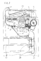
- Fig. 2 illustrates the structure of the printing machine in Fig. 1
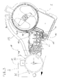
- Fig. 3 shows the arrangement of the essential portions in the structure of Fig. 2.
- an image forming apparatus is constituted of a printing machine.
- This printing machine includes three paper cassettes 10 for retaining printing sheets, left and right doors 11 and 12 of a print mechanism shown in Fig. 2, a stacker 13 provided at an upper portion for retaining printed sheets, and an operation panel 14 for operating the printing machine.
- a printing machine includes three paper cassettes 10 for retaining printing sheets, left and right doors 11 and 12 of a print mechanism shown in Fig. 2, a stacker 13 provided at an upper portion for retaining printed sheets, and an operation panel 14 for operating the printing machine.
- the print mechanism has a rotatable photosensitive drum 30, a precharger 31 for electrifying the photosensitive drum 30, a laser optical unit 32 which writes a light image on the photosensitive drum 30 to form a latent image thereon, a developing apparatus 4 for developing the latent image on the photosensitive drum 30 with a toner, a transfer/separating unit 33 for transferring a toner image of the photosensitive drum 30 onto a sheet to be fed and separating this sheet, and a cleaner 34 for cleaning the photosensitive drum 30 after the image transfer.
- a developer cartridge 5 is attached to this developing apparatus 4 for collecting the developer, supplying the developer, supplementing a toner and collecting a waste toner.
- a paper feeding system has pick rollers 20 for picking sheets in the sheet cassettes 10, feed rollers 21 for feeding picked sheets to a hold roller 22, and a heat roller fixing apparatus 23 for thermally fixing the sheet after the toner-image transfer.
- This paper feeding system also has a blade wheel 24 for directing the rear end of the sheet from the heat roller fixing apparatus 23 toward a back-printing feeding passage 26, switchback rollers 25 for feeding the sheet from the heat roller fixing apparatus 23 in the discharging direction and then feeding that sheet to the back-printing feeding passage 26, guide rollers 27 for guiding the ejection of the sheet, discharge rollers 28, the stacker 13 for retaining the ejected sheet, and the back-printing feeding passage 26 for feeding the sheet from the switchback rollers 25 to the hold roller 22 using feed rollers.
- this printing machine After the photosensitive drum 30 is electrified by the precharger 31, a light image is written on the drum 30 by the optical system unit 32 to form a latent image thereon. Then, the photosensitive drum 30 is developed to have a toner image by the developing apparatus 4. In the meantime, the printing sheet is picked up from the associated sheet cassette 10 by the pick rollers 20, and is fed to the hold roller 22 by the feed rollers 21. This sheet is held by the resist roller 22 to be in synchronism with the toner image on the photosensitive drum 30.
- the transfer/separating unit 33 transfers the toner image of the photosensitive drum 30 onto the sheet fed by the hold roller 22, and then separates the sheet from the photosensitive drum 30.
- the sheet is fed toward the switchback rollers 25. Further, the sheet is fed toward the stacker 13 by the switchback rollers 25.
- the switchback rollers 25 stop feeding the sheet.
- the rear end of the sheet is directed toward the back-printing feeding passage 26 by the counterclockwise rotation of the blade wheel 24.
- the switchback rollers rotate in the reverse direction to feed the sheet to the back-printing feeding passage 26.
- the sheet is further fed to the resist roller 22 by the feed rollers of the back-printing feeding passage 26.
- the transfer/separating unit 33 transfers the toner image of the photosensitive drum 30 on the back of the sheet and separates it from the photosensitive drum 30 as per the front printing of the sheet.
- the sheet is fed toward the switchback rollers 25. Further, the sheet is fed toward the stacker 13 by the switchback rollers 25, and is discharged on the stacker 13 by discharge rollers 28. Double-side printing is performed on the sheet in this manner. For single-side printing, the sheet is discharged on the stacker 13 after printing is done only on the top surface of the sheet.
- the sheet cassettes 10 are mounted into the machine from the front and the sheet is discharged onto the overlying stacker 13 as shown in Fig. 1.
- This design requires no space on either side of the machine, thus making it possible to reduce the space. Further, as the discharging passage is used in the switchback path, the double-side printing machine can be made compact.
- the developing apparatus 4 has a developing roller 40, which rotates counterclockwise to supply the developer to the photosensitive drum 30, a pair of stirring screws 41 for stirring the developer, which is comprised of toner and carrier, a collecting blade 48 for scraping the developer off the developing roller 40 and returning the scraped developer back to the stirring screws 41, and a toner supply roller 43 for supplying a toner into the developing apparatus 4. Further, an injection port 44 for receiving the developer and toner from the cartridge 5. This injection port 44 faces outlet ports 72 and 73 of the cartridge 5, which will be described later.
- a discharge port 45 for discharging the developer and a discharge shutter 46 which covers the discharge port 45.
- the discharge port 45 and discharge shutter 46 face a collecting section 77 of the cartridge 5.
- This cartridge 5 is positioned opposite the photosensitive drum 30 of the developing apparatus 4. Therefore, it is possible to dispose only the developing apparatus 4 in the space around the photosensitive drum 30 and arrange the cartridge 5 in the free space therearound. It is thus unnecessary to provide space for the cartridge 5 in the narrow space around the photosensitive drum 30, contributing to making the image forming apparatus compact. As the cartridge 5 is placed in the free space, a relatively large cartridge 5 can be installed. Further, the cartridge 5 is disposed by the developing apparatus 4, the cartridge 5 can be made smaller.
- the photosensitive drum 30, the precharger 31 and the cleaner 34 are assembled into a single drum unit 3, and are detachable from the apparatus.
- a waste toner carrying pipe 35 for conveying the residue toner (waste toner) on the photosensitive drum 30 removed by the cleaner 34.
- This pipe 35 is connected to a waste toner discharging section 36 provided at the upper portion of the cartridge 5 to discharge the waste toner to the cartridge 5.
- This design allows for the supply of the developer and the supplement of the toner to the developing apparatus 4. In addition, it is possible to collect the developer from the developing apparatus 4 to the cartridge 5 as well as to collect the waste toner from the cleaner 34 to the cartridge 5.
- Fig. 4 is a top view of the developing apparatus
- Fig. 5 is a cross section taken along the line A-A in Fig. 4
- Fig. 6 is an explanatory diagram of a toner density sensor
- Fig. 7A is a perspective view of the stirring screw
- Fig. 7B is a perspective view of the toner density sensor.
- a pair of stirring screws 41a and 41b are each constituted of a spiral screw.
- the stirring screws 41a and 41b rotate in the opposite directions.
- a partition 41c is provided between the stirring screws 41a and 41b.
- the stirring screw 41b stirs the developer while conveying it rightward in the diagram.
- the developer conveyed by the stirring screw 41b gets over the partition 41c onto the stirring screw 41a.
- the stirring screw 41a stirs the developer while conveying the developer leftward in the diagram to supply it to the developing roller 40.
- This design permits the developer to be sufficiently stirred and minimizes the developer that will not be stirred. This design is indicated by PCT application No. JP92/01452 dated November 9, 1992.
- those portions of a container 49 of the developing apparatus 4 which correspond to the stirring screws 41a and 41b are each formed into a U shape. Accordingly, the developer that will not be stirred can be minimized.
- the developer in the developing apparatus 4 is discharged from the discharge port 45 by the conveying force of the stirring screws 41a and 41b.
- the bottom of the container 49 has a U shape, the developer that will not be discharged can be minimized, so that the efficiency of exchanging developers can be improved.
- the developing roller 40 has a fixed magnetic roller and a rotatable sleeve on which a magnetic brush is formed.
- the height of the magnetic brush on the sleeve is restricted by a doctor blade 40-1.
- a toner density sensor 47 shown in Fig. 7B below the stirring screw 41a is provided a toner density sensor 47 shown in Fig. 7B.
- This toner density sensor 47 constituted of a magnetic sensor, detects the toner density of the developer. The reason why the toner density sensor 47 is provided there is to sense the toner density near the developing roller 40 so that the toner density on the developing roller 40 can be detected accurately.
- the toner density sensor 47 is attached so that its upper end will not be positioned below the U-shaped bottom of the container 49.
- the toner density sensor 47 is attached slightly below the bottom of the container 49 in order to avoid a contact with the stirring screw 41a. In this case, however, the developer stays in the clearance between the bottom of the container 49 and the sensor 47, and the toner density cannot be detected accurately.
- the toner density sensor 47 is attached so that its upper end is not positioned below the U-shaped bottom of the container 49.
- the toner density sensor 47 in this arrangement may contact the stirring screw 41a. To avoid this problem, that outer surface of the stirring screw 41a which faces the toner density sensor 47 is cut so that the screw 41a will not hit against the top end of the toner density sensor 47.
- Fig. 8 is a front view of the drum unit shown
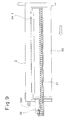
- Fig. 9 is a side view of the drum unit
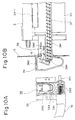
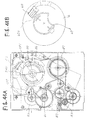
- Fig. 10A is a front view of a waste toner collecting mechanism shown
- Fig. 10B is a side view of the toner collecting mechanism
- Fig. 11 is a diagram for explaining the operation of the toner collecting mechanism
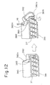
- Fig. 12 is an explanatory diagram of a modification of the toner collecting mechanism
- Fig. 13 is an explanatory diagram of another modification of the toner collecting mechanism.
- the drum unit 3 has the photosensitive drum 30, the precharger 31 and the cleaner 34 assembled as a single unit.
- the cleaner 34 has a scraping blade 34-1 for scraping the residue toner off the photosensitive drum 30, a cleaning roller 34-2 that rotates to remove the residue toner on the photosensitive drum 30, and a waste toner discharging screw 37 for discharging the toner, removed by the blade 34-1 and roller 34-2 and accumulated in the cleaner 34, outside.
- a toner discharging mechanism 38 is provided at the distal end of the waste toner discharging screw 37 of the cleaner 34 in the drum unit 3.
- This toner discharging mechanism 38 protrudes from the end portion of the drum unit 3.
- this toner discharging mechanism is provided with a toner discharging pipe 381 provided around the distal end of the discharging screw 37, a protruding block 380 of the drum unit 3, and a cap 382 supported on the protruding block 380 by a pin 383 to cap the distal end of the toner discharging pipe 381.
- This cap 382 is provided to cap the distal end of the toner discharging pipe 381 to prevent the toner from leaking from the cleaner 34 when the drum unit 3, detachably attached to the image forming apparatus, is detached therefrom for replacement.
- a frame 15 of the apparatus is provided with a hole where the toner discharging mechanism 38 of the cleaner 34 is inserted, an engaging projection 16 provided at the upper portion of the hole, and a waste toner carrying block 39 so provided as to cover the hole.
- the waste toner carrying pipe 35 which has been explained with reference to Fig. 3, is connected to the waste toner carrying block 39 as shown in Fig. 10A. Disposed in this pipe 35 is a carrying screw 350 which is rotated by a drive shaft 351.
- the toner carrying operation will now be described.
- the drum unit 3 in Fig. 9 is inserted into the apparatus in the arrow direction in the diagram for its replacement.
- the toner discharging mechanism 38 of the cleaner 34 enters the hole of the frame 15. Accordingly, an engage lever 382a of the cap 382 of the toner discharging mechanism 38 abuts on the engaging projection 16 of the frame 15, thereby rotating the cap 382 around the pin 383, as shown in Figs. 10A and 10B.
- the distal end of the discharging pipe 381 becomes free so that the toner can be discharged from an opened portion 384 by the discharging screw 37. This is illustrated in Fig. 11.
- the lower portion of the distal end of the discharging pipe 381 becomes free by the cap 382 to discharge the waste toner from the lower portion 384 of the discharging pipe 381 as shown in Fig. 11.
- the discharged toner falls in the waste toner carrying block 39 and is carried inside the waste toner carrying pipe 35 by the carrying screw 350 to a waste toner discharging section 36 shown in Fig. 3.
- Fig. 12 illustrates a modification of the toner discharging mechanism 38.
- an obliquely cut portion 381b is provided at the distal end of the discharging pipe 381 and the cap 382 is provided with a protruding portion 382a in this modification.
- the cap 382 when the cap 382 is open, only the lower portipn of the end face of the discharging pipe 381 is opened.
- the toner absorbs water and the fluidity gets lower, the toner will not fall from the aforementioned opened portion 384 and will be carried to the cap 382.
- the toner is kept pressed by the cap 382 by the discharging screw 37, the toner sticks firmly on the cap 382.
- the obliquely cut portion 381b is provided on the discharging pipe 381 to make the opened portion wider. Accordingly, the toner discharging port becomes wider so that the toner can surely be discharged. Even when the toner absorbs water to reduce the fluidity, it is possible to prevent the toner from firmly sticking on the cap 382.
- Fig. 13 illustrates another modification of the toner discharging mechanism 38.
- This modification has an auxiliary pipe 381c provided at the front edge portion of the discharging pipe 381 as shown in Fig. 13.
- This auxiliary pipe 381c is engaged slidable in the axial direction of the discharging pipe 381.
- the auxiliary pipe 381c is connected to a spring 381d provided at the protruding block 380a of the drum unit 3 and is urged toward the cap 382. Therefore, the auxiliary pipe 381c abuts against the cap 382 to accomplish the capping of the discharging pipe 381, as shown in Fig. 13.
- the cap 382 When the drum unit 3 is installed, the cap 382 is rotated by the engaging projection 16, and the auxiliary pipe 381c abuts against another engaging projection 17 provided on the frame 15 to compress the spring 381d and move away from the front end portion of the discharging pipe 381.
- the opened portion of the discharging pipe 381 becomes wider accordingly. Therefore, the toner discharging port becomes wide to allow the toner to be surely discharged as in the modification of Fig. 12. Even when the toner absorbs water to reduce the fluidity, therefore, it is possible to prevent the toner from firmly sticking on the cap 382.
- FIG. 14 shows the outline of a developer cartridge according to one embodiment of the present invention
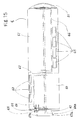
- Fig. 15 is a front view of an inner drum of the cartridge
- Fig. 16 is an explanatory diagram of the inner drum of the cartridge shown in Fig.
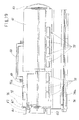
- Fig. 17 is a front view of an outer case of the cartridge shown in Fig. 14
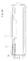
- Fig. 18 is a cross-sectional view of the outer case of the cartridge shown in Fig. 17.
- a top handle 50 is provided at the top of the cartridge 5 for easier holding by a human hand, and a side handle 51 is provided on the right-hand side of the cartridge 5 which will be used to manually detach the cartridge 5.
- the cartridge 5 comprises an inner drum 6 and an outer case 7 having an inner drum retaining section 70 to retain the inner drum 6 and a waste developer storage room 71.
- This waste developer storage room 71 serves to store the used developer of the developing apparatus 4.
- the outer case 7 is provided with developer injection ports 72 and toner injection ports 73 at the lower portion of the inner drum 6 retaining section 70, and is provided with a waste toner collecting port 75 at the upper portion of the drum retaining section 70.
- the waste developer storage room 71 of the outer case 7 is provided with a collecting shutter 74 which covers the collecting port 77.
- the interior of the inner drum 6 is divided into right and left portions by a partition 62.
- One is a developer storage room 60 for storing an unused developer, and the other is a toner storage room 61 for storing a supplemental toner.
- the developer storage room 60 is provided with developer supply ports 63 for discharging the unused developer and a paddle 64 for discharging the developer.
- the toner storage room 61 is provided with toner supply ports 65 for discharging a supplemental toner and a paddle 66 for discharging the toner.
- a paddle shaft 64a Disposed in the centre of the inner drum 6 is a paddle shaft 64a for driving both paddles 64 and 66.
- the paddles are generally in the form of bars or baffles extending substantially axially over the length of their respective chambers near the drum wall, so as to agitate the material in the respective chambers 60,61.
- the side handle 51 is provided at the right end of the inner drum 6.
- the left end of the inner drum 6 is provided with a rotatable engaging portion 67, which has a lock projection 67a and engages with drive means to rotate the inner drum 6, a new/old discrimination section 68 for discriminating if the cartridge is new or old, and a lock pawl 69.
- Fig. 16A there are three developer supply ports 63 provided on the left end of the inner drum 6, with a leak preventing seal 63a placed around the ports 63.
- Fig. 16B there are four toner supply ports 65 provided at the right end of the inner drum 6, with a leak preventing seal 65a placed around the ports 65.
- the developer supply ports 63 are located apart from the toner supply ports 65 by 120 degrees in the rotational direction of the inner drum 6 as shown in Fig. 15.
- the outer case 7 is provided with the top handle 50, the inner drum retaining section 70 for retaining the inner drum 6 and the waste developer storage room 71 for storing a waste developer as mentioned earlier.
- the waste toner collecting port 75 Provided at the upper portion of the inner drum retaining section 70 are the waste toner collecting port 75, a shutter opening/closing projection 75a for opening the discharge shutter of the waste toner discharging section 36 (see Fig. 3), and an outer case lock pawl 76.
- the waste developer storage room 71 is provided with a protruding block 71a.
- the collecting port 77 for collecting the used developer and a discharging screw 78 for guiding the used developer into the storage room 71 are provided at the left-hand portion of the protruding block 71a. Further, the bottom 71b of the waste developer storage room 71 is inclined with respect to the face of the collecting port 77 of the protruding block 71a.
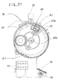
- FIG. 19 is a front view of the cartridge assembly in Fig. 14, Fig. 20 is a rear view of the cartridge assembly in Fig. 19, Fig. 21 is a side view of the cartridge assembly in Fig. 19, and Fig. 22 is a perspective view of the cartridge assembly in Fig. 19.
- the cartridge 5 is completed by placing the inner drum 6 in the inner drum retaining section 70.
- the cartridge 5 is provided with the top handle 50, the waste toner collecting port 75, the shutter opening/closing projection 75a, and the outer case lock pawl 76 at the top portion.
- the cartridge 5 is further provided with the developer injection ports 72 and toner injection ports 73 at the lower portion.
- the collecting shutter 74 is provided in the waste developer storage room 71 at the lower portion of the cartridge 5. This collecting shutter 74 has a projection 74a which engages with the projecting portion of the developing apparatus to be open or closed.
- the discharging screw 78 is provided at the lower portion of the waste developer collecting port 77.
- a seal tab a1 for covering the waste toner collecting port 75 and a seal tab a2 for covering the developer injection ports 72 and toner injection ports 73 to seal those ports 77, 72 and 73, respectively.
- the rotatable engaging portion 67 having the lock projection 67a is provided at the left end of the cartridge 5, and the paddle shaft 64a, the new/old discrimination section 68, the lock pawl 69 and a characteristic setting section 79 which indicates the characteristics of the stored developer and toner are provided at the center portion of the cartridge 5.
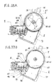
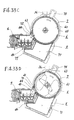
- FIG. 23 is an explanatory diagram of a drive mechanism for driving the cartridge assembly in Fig. 19
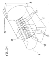
- Fig. 24 is a perspective view showing the cartridge of Fig. 19 mounted in a developing apparatus
- Fig. 25 is a diagram showing the connection between the mounted cartridge and a drive mechanism
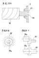
- Figs. 26A through 26C present explanatory diagrams of the discharging screw of the cartridge
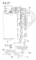
- Fig. 27 is an explanatory diagram of the waste toner conveying mechanism shown in Fig. 23
- Fig. 28 is a diagram showing the arrangement of the essential portions of the waste toner conveying mechanism shown in Fig. 27.
- a frame 9, which is for setting the cartridge 5, has a drive mechanism 8 provided at the back to drive the cartridge 5.
- This frame 9 is provided with a mounting hole 90 in which the rotatable engaging portion 67 and engaging projection 67a of the cartridge 5 are to be fitted, a lock release rod 91 which unlocks the outercase lock pawl 76 of the cartridge 5 to permit the rotation of the inner drum 6, and a new/old setting rod 92 for activating the new/old discriminating section 68.
- the drive mechanism 8 is provided with a drive shaft 80.
- This drive shaft 80 has a paddle drive portion 80a and a drive projection 80b.
- the paddle drive portion 80a engages with the paddle shaft 64a of the cartridge 5 to rotate the paddle shaft 64a.
- the drive projection 80b engages with the rotatable engaging portion 67 of the cartridge 5 to rotate the inner drum 6.
- the drive mechanism 8 is also provided with a developing-apparatus drive shaft 81 (see Fig. 25) for driving the toner supply roller 43 of the developing apparatus 4, a shutter opening/closing lever 82 (see Fig. 25) for opening and closing the discharge shutter 46 of the developing apparatus 4, and a discharging screw drive mechanism 83 (see Fig. 25) for rotating the discharging screw 78 of the cartridge 5.
- the drive mechanism 8 further has a characteristic detecting switch 84 for detecting the setting of the character setting section 79 of the cartridge 5, a cartridge right-end sensor CP1 for detecting the right-hand rotational end of the inner drum 6, a cartridge left-end sensor CP2 for detecting the left-end rotational end of the inner drum 6, and a new/old discriminating switch CS which is activated by the new/old discriminating section 68 of the cartridge 5.
- the waste toner discharging section 36 is provided at the upper portion of the drive mechanism 8.
- the cartridge 5 is inserted in the frame 9 so that the rotatable engaging portion 67 of the cartridge 5 is fitted in the mounting hole 90. Then, the cartridge 5 is turned rightward so that the engaging projection 67a of the rotatable engaging portion 67 engages with the frame 9 to lock the cartridge 5, thereby disabling the removable of the cartridge 5.
- the toner injection ports 73 of the cartridge 5 face the toner supply roller 43 at the injection port 44 of the developing apparatus 4, while the developer injection ports 72 of the cartridge 5 face the shaft 43a of the toner supply roller 43 at the injection port 44 of the developing apparatus 4, as shown in Fig. 24.
- the waste toner discharging section 36 of the drive mechanism 8 faces the waste toner collecting port 75 of the cartridge 5. Further, the rotatable engaging portion 67 of the inner drum 6 of the cartridge 5 engages with the drive projection 80b of the drive shaft 80 of the drive mechanism 8, so that the inner drum can be rotated. The paddle shaft 64a of the inner drum 6 of the cartridge 5 engages with the paddle drive portion 80a of the drive shaft 80, allowing the paddle shaft 64a to rotate.
- the discharging screw 78 is connected to the screw drive shaft 83 of the drive mechanism 8.
- a bearing portion 52 of the cartridge 5 is set large for a screw shaft 78a of this discharging screw 78, as shown in Figs. 26A and 26B to provide a clearance to allow the screw shaft 78a to move. Even if the center of the screw shaft 78a is misaligned with the center of the screw drive shaft 83 as shown in Fig. 26C, therefore, when the screw drive shaft 83 rotates, the centering is made to align the shaft centers with each other.
- the shutter 36a covering the discharge port of the waste toner discharging section 36 is pushed by the shutter driving projection 75a at the waste toner collecting port 75 to move while compressing the spring 36b.
- the discharge port is open and faces the waste toner collecting port 75.
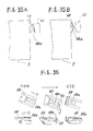
- FIG. 31 presents an explanatory diagram (No. 1) of a cartridge exchanging sequence
- Figs. 32A and 32B are explanatory diagrams of the attaching operation of the cartridge
- Figs. 33A through 33F are explanatory diagrams of the cartridge exchanging operation (No. 2)
- Figs. 34A and 34B present diagrams for explaining how to detach the cartridge
- Figs. 35A and 35B are diagrams for explaining a cartridge discrimination at the time the cartridge is attached
- Fig. 36 is a diagram for explaining an automatic setting operation at the time the cartridge is attached. The following description will be given along the exchanging sequence illustrated in Fig. 31.
- the operator bends the tabs a1 and a2 of the cartridge 5 and then pulls out the cartridge 5 to unseal the waste toner collecting port 75, developer injection ports 72 and toner injection ports 73 of the outer case 7. Then, as shown in Fig. 32B, the operator mounts the cartridge 5 into the apparatus. If the cartridge 5 is new at this time, a slide projection 68a of the new/old discriminating section 68 is positioned on the left-hand side as shown in Fig. 36. Therefore, the new/old discriminating switch CS of the drive mechanism 8 is set on as shown in Fig. 35A to allow the apparatus to recognize the mounting of the new cartridge 5, and the exchanging sequence will start.
- the slide projection 68a of the new/old discriminating section 68 is positioned on the right-hand side as shown in Fig. 36. In this case, therefore, the new/old discriminating switch CS of the drive mechanism 8 will not be set on as shown in Fig. 35B so that the exchanging sequence will not start.
- the slide projection 68a slides rightward in the diagram by the new/old setting rod 92 of the frame 9 as shown in Fig. 36, so that the cartridge 5 is set as an old one. Accordingly, once the cartridge 5 is mounted into the apparatus, it is set as an old cartridge, so that even if this cartridge is newly mounted later, it will be discriminated as an old one and the exchanging sequence will not start to disable the use of this cartridge. It is therefore possible to prevent the exchanging sequence from starting with the erroneous mounting of an old cartridge 5 by the operator.
- the developer collecting shutter 74 of the cartridge 5 is open as shown in Fig. 25, and the shutter 36a of the waste toner discharging section 36 is open as shown in Fig. 27.
- the lock pawl 76 of the outer case 7 is disengaged from the lock pawl 69 of the inner drum 6 by the lock release rod 91, permitting the inner drum 6 to rotate.
- the cartridge 5 is securely positioned in the apparatus.
- the projection 67a of the rotatable engaging portion 67 of the inner drum 6 sets the drive rightward rotational position switch CP1 on. This allows the apparatus side to recognize the completion of the mounting of the cartridge 5.
- the toner injection ports 73 in the outer case 7 of the cartridge 5 face the injection port 44 of the developing apparatus 4 as shown in Fig. 33A.
- the collecting port 77 in the outer case 7 of the cartridge 5 is positioned directly below the discharge port 45 of the developing apparatus 4.
- the cartridge 5 is arranged opposite to the photosensitive drum 30 in a tilted state.
- the developer injection ports 63 of the inner drum 6 face the discharge port of the waste toner discharging section 36, while the toner supply ports 65 of the inner drum 6 face the tone injection ports 73 in the outer case 7.
- the drive mechanism 8 turns the inner drum 6 leftward to position it as shown in Fig. 33B. This releases the state of the toner supply ports 65 of the inner drum 6 facing the tone injection ports 73 of the outer case 7 and closes the latter ports 73. In this state, the drive mechanism 8 activates the shutter opening/closing lever 82 to open the discharge shutter 46 of the developing apparatus 4 and cause the screw drive shaft 83 to drive the discharging screw 78. Then, the developing apparatus 4 is driven for one minute by an unillustrated main motor.
- the developer in the developing apparatus 4 falls from the discharge port 45 of the developing apparatus into the waste developer storage room 71 through the collecting port 77 of the cartridge 5, and is discharged into the waste developer storage room 71 by the discharging screw 78, as shown in Fig. 33B, accomplishing the collection of the waste developer.
- the drive mechanism 8 activates the shutter opening/closing lever 82 to close the discharge shutter 46 of the developing apparatus 4, considering that the whole developer in the developing apparatus 4 have been collected. Then, the drive mechanism 8 stops causing the screw drive shaft 83 to drive the discharging screw 78, and stops driving the developing apparatus 4 by the main motor.
- the drive mechanism 8 rotates the inner drum 6 until the drive leftward rotational position switch CP2 is set on by the projection 67a of the rotatable engaging portion 67 of the inner drum 6.
- the developer injection ports 63 of the inner drum 6 face the developer injection ports 72 of the outer case 7 and the ports 72 are open as shown in Fig. 33C.
- the drive mechanism 8 then causes the paddle drive shaft 80a to drive the paddle shaft 62, thereby rotating the paddle 64. Accordingly, the developer in the developer storage room 60 in the inner drum 6 is supplied through the injection port 44 into the developing apparatus 4. As the unused developer in the developer storage room 60 is supplied in parallel through the three developer injection ports 72, the developer supplying time is shortened.
- the drive mechanism 8 rotates the inner drum 6 until the drive rightward rotational position switch CP1 is set on by the projection 67a of the rotatable engaging portion 67 of the inner drum 6. Accordingly, the developer injection ports 63 of the inner drum 6 face the discharge port of the waste toner discharging section 36, as shown in Fig. 33D.
- the toner supply ports 65 of the inner drum 6 face the toner injection ports 73 of the outer case 7.
- the apparatus is ready for normally printing and the supplement of the toner and the collection of the waste tone are possible. That is, as the paddle shaft 62 is driven by the paddle drive shaft 80a to rotate the paddle 66, the toner is supplied to the toner supply roller 43 from the toner storage room 61. Under the toner density control, the drive mechanism 8 causes the developing-apparatus drive shaft 81 to rotate the toner supply roller 43 to supply the toner into the developing apparatus 4. Further, the waste toner from the cleaner 34 is collected into the developer storage room 60 of the cartridge 5 through the waste toner carrying pipe 35 and the waste toner discharging section 36. That is, the developer storage room 60 is used as a collecting room for the waste toner.
- the amount of the toner in the toner storage room 61 falls down to a level to deteriorate the carrier of the unused developer in the developer storage room 60, the toner-empty state and the deterioration of the developer occur simultaneously, providing a high cartridge-exchanging efficiency.
- the drive mechanism 8 When detecting the depression of the exchange switch, the drive mechanism 8 rotates the inner drum 6 leftward to the position shown in Fig. 33E. As a result, the state of the toner supply ports 65 of the inner drum 6 facing the toner injection ports 73 of the outer case 7 is released, the latter ports 73 are closed and the cartridge 5 is locked. In this state, the drive mechanism 8 causes the developing-apparatus drive shaft 81 to rotate the toner supply roller 43 to allow the residual toner at the injection port 44 of the developing apparatus 4 to be collected in the developing apparatus 4, thereby preventing the sputtering of the toner at the time the cartridge 5 is detached therefrom.
- the drive mechanism 8 rotates the inner drum 6 rightward so that the projection 67a of the rotatable engaging portion 67 of the inner drum 6 comes to the mounting hole 90 of the frame 9. This unlocks the cartridge 5 so that it can be detached.
- the detachment of the cartridge 5, the exchange of the developer, the supplement of the toner and the collection of the waste toner can be accomplished with a single cartridge 5 and in a single detaching operation.
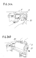
- Fig. 37 is a cross-sectional front view of the drive mechanism in Fig. 19, Fig. 38 is a front view of the drive mechanism in Fig. 37, Fig. 39 is a lower side view of the drive mechanism in Fig. 37, Fig. 40 is a left side view of the drive mechanism in Fig. 37, Fig. 41 is an explanatory diagram of the developing-apparatus drive shaft shown in Fig. 37, Figs. 42A through 42D present explanatory diagrams of a paddle shaft shown in Fig. 37, and Figs. 43 and 44 are diagrams showing the structures of cams of the drive mechanism in Fig. 37.
- a single drive motor 85 which rotates a gear 89a of the developing-apparatus drive shaft 81 to thereby rotate the drive shaft 81.
- This drive shaft 81 drives a first cam 86 for the drive shaft 80 and a drive pulley 89c of a second cam 87 through a pulley 89b by means of a belt 88a.
- the second cam 87 drives a shutter opening/closing lever drive cam 82a and a drive gear 89f of the screw drive shaft 83 through pulleys 89d and 89e by means of a belt 88b.
- the cartridge left position detecting switch CP1, new/old discriminating switch CS, a timing sensor TMH and the cartridge rightward position detecting switch CP2 are provided around this drive shaft 80.
- the characteristic detecting switch 84 As shown in Fig. 38.
- the drive pulley 89c which is driven by the belt 88a, has a pin that engages with a cam groove of the second cam 87 (see Fig. 44 for the groove).
- the shutter opening/closing lever drive cam 83a and the screw drive shaft 83 are driven.
- the shutter opening/closing lever 82 has an engagement metal fitting 82b and a spring 82c. As the metal fitting 82b moves along the cam groove of the drive cam 82a that is driven by the belt 88b, therefore, the shutter opening/closing lever 82 moves rightward and leftward in the diagram. The opening/closing of this shutter is detected by a shutter opening/closing detecting switch STP provided at the rear end of the shutter opening/closing lever 82.
- the drive pulley 86a which is driven by the belt 88a, has a pin that engages with a cam groove of the first cam 86 (see Fig. 43 for the groove).
- the drive pulley 86a directly drives the paddle drive shaft 80a.
- the paddle drive shaft 80a movable rightward and leftward in the diagram, is urged in the right direction in the diagram by a leaf spring 80c.
- This paddle shaft 80a has inclined projections 800 and 801 provided on the respective sides of a center recess 802, as shown in Figs. 42A through 42D.
- the paddle shaft 64a of the cartridge 5 which has a shape of a slotted screwdriver
- the paddle shaft 64a is driven by the inclined projections 800 and 801 with respect to the rightward turn in Figs. 42A and 42B.
- the paddle shaft 64a slides along the inclined surfaces of the inclined projections 800 and 801 so that the paddle drive shaft 80a shifts leftward in Fig. 40 against the force of the leaf spring 80c, inhibiting the driving of the paddle shaft 64a.
- the paddle drive shaft 80a and paddle shaft 80 constitute a one-way clutch.
- the developing-apparatus drive shaft 81 comprises an intermediate member 81a, which has a horizontal projection with a shape of a slotted screwdriver at the left-hand end and a vertical projection with a shape of a slotted screwdriver at the right-hand end, and a drive shaft 81b having a vertical flat recess, with respect to the roller shaft 43 having a shape of a slotted screwdriver. Accordingly, the drive shaft 81 has a degree of freedom in the vertical and horizontal directions in the diagram, and can be driven in accordance with a change in the roller shaft 43 of the developing apparatus 4.
- the inner drum 6, paddles 64 and 66, the toner supply roller 43, the developer discharge shutter 46 and the discharging screw 78 are sequentially driven by a single motor 85 in the above manner.
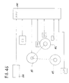
- Fig. 45 is a control block diagram according to one embodiment of the present invention
- Fig. 46 and 47 present time charts for a developer exchanging operation according to one embodiment of the present invention
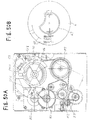
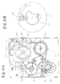
- Figs. 48A, 48B, 49A, 49B, 50A, 50B, 51A and 51B present explanatory diagrams of a developer exchanging operation according to one embodiment of the present invention
- Figs. 52A through 52D are diagrams for explaining the function of the cams in the developer exchanging operation.
- a control section 100 constituted of a microprocessor (MPU), detects the characteristics of the developer and toner from the output of the cartridge characteristic sensor 84 to control a precharging voltage, a developing bias voltage, etc., starts the exchanging sequence according to the output of the new/old discriminating switch CS, and controls the motor 85 based on the outputs of the timing sensor TMH, the cartridge right position detecting switch CP1, the cartridge left position detecting switch CP2 and the shutter opening/closing detecting switch STP.
- MPU microprocessor
- the operator mounts the cartridge 5 into the apparatus and rotates the inner drum 6 of the cartridge 5 rightward.
- the projection 67a of the rotatable engaging portion 67 of the inner drum 6 engages with the frame 9, locking the cartridge 5, and the projection 67a of the rotatable engaging portion 67 of the inner drum 6 sets the drive rightward rotational position switch CP1 on, as shown in Fig. 48B.
- the drive mechanism 8 comes in the state of Fig. 48A.
- the control section 100 starts the exchanging operation and repeats the forward and reverse rotations of the motor 85 twice. Consequently, the first cam 86 turns in the reverse direction (leftward) to turn the inner drum 6 leftward to the position shown in Figs. 49A and 49B. This releases the state of the toner supply ports 65 of the inner drum 6 facing the tone injection ports 73 of the outer case 7 and closes the latter ports 73. Then, the control section 100 performs the forward and reverse rotations of the motor 85 once to turn the second cam 87 in the reverse direction. Next, the control section 100 turns the motor 85 in the forward direction to cause the forward turning of the second cam 87. As a result, the shutter opening/closing lever 82 is activated to drive the discharging screw 78 and causes the main motor to drive the developing apparatus 4 for one minute.
- the developer in the developing apparatus 4 falls from the discharge port 45 of the developing apparatus into the waste developer storage room 71 through the collecting port 77 of the cartridge 5, and is discharged into the waste developer storage room 71 by the discharging screw 78, as shown in Fig. 33B, accomplishing the collection of the waste developer.
- the control section 100 rotates the motor 85 in the reverse direction, considering that the whole developer in the developing apparatus 4 have been collected.
- the second cam 87 turns in the reverse direction to activate the shutter opening/closing lever 82 to close the discharge shutter 46 of the developing apparatus 4.
- the control section 100 stops causing the screw drive shaft 83 to drive the discharging screw 78, and stops driving the developing apparatus 4 by the main motor.
- the control section 100 repeats the forward and reverse rotations of the motor 85 twice to turn the first cam 86 in the reverse direction (leftward) so that the inner drum 6 rotates leftward as shown in Figs. 50A and 50B.
- the inner drum 6 is turned until the drive left position switch CP2 is set on by the projection 67a of the rotatable engaging portion 67 of the inner drum 6.
- the developer injection ports 63 of the inner drum 6 face the developer injection ports 72 of the outer case 7 as shown in Fig. 33C.
- the control section 100 therefore causes the paddle drive shaft 80a to drive the paddle shaft 62, thereby rotating the paddle 64. Consequently, the developer in the developer storage room 60 in the inner drum 6 is supplied through the injection port 44 into the developing apparatus 4, and the developer exchanging operation will be terminated.
- the control section 100 repeats the forward and reverse rotations of the motor 85 twice to turn the first cam 86 in the reverse direction (rightward), thereby rotating the inner drum 6 until the drive right position switch CP1 is set on by the projection 67a of the rotatable engaging portion 67 of the inner drum 6, 'as shown in Figs. 51A and 51B. Accordingly, the developer injection ports 63 of the inner drum 6 face the discharge port of the waste toner discharging section 36, as shown in Fig. 33D. The toner supply ports 65 of the inner drum 6 face the toner injection ports 73 of the outer case 7.
- the apparatus is ready for normally printing and the supplement of the toner and the collection of the waste tone are possible. That is, as the paddle shaft 62 is driven by the paddle drive shaft 80a to rotate the paddle 66, the toner is supplied to the toner supply roller 43 from the toner storage room 61. Under the toner density control, the control section 100 causes the developing-apparatus drive shaft 81 to rotate the toner supply roller 43 to supply the toner into the developing apparatus 4. Further, the waste toner from the cleaner 34 is collected into the developer storage room 60 of the cartridge 5 through the waste toner carrying pipe 35 and the waste toner discharging section 36.
- the control section 100 When detecting the depression of the exchange switch, the control section 100 performs the forward and reverse rotations of the motor 85 once to turn the first cam 86 in the reverse direction. Accordingly, the drive mechanism 8 rotates the inner drum 6 leftward to the position shown in Fig. 33E. As a result, the state of the toner supply ports 65 of the inner drum 6 facing the toner injection ports 73 of the outer case 7 is released, the latter ports 73 are closed and the cartridge 5 is locked.
- control section 100 causes the developing-apparatus drive shaft 81 to rotate the tone supply roller 43 to allow the residual toner at the injection port 44 of the developing apparatus 4 to be collected in the developing apparatus 4, thereby preventing the sputtering of the toner at the time the cartridge 5 is detached therefrom.
- control section 100 repeats the forward and reverse rotations of the motor 85 twice to turn the first cam 86 in the forward direction (rightward). Consequently, the inner drum 6 is rotated rightward so that the projection 67a of the rotatable engaging portion 67 of the inner drum 6 comes to the mounting hole 90 of the frame 9, as shown in Fig. 33F. This unlocks the cartridge 5 so that it can be detached.
- the detachment of the cartridge 5, the exchange of the developer, the supplement of the toner, the rotation of the paddles, etc. can be accomplished by the functions of the cams 86 and 87 by controlling a single motor 85.
- the developer discharge shutter 46 is driven by the second cam 87.
- the pin enters the cam 87 and the shutter 46 is kept closed (Fig. 52A).
- the motor 85 rotates counterclockwise, the pin enters the cam groove B along the cam 87, and the shutter 46 is open (Fig. 52B).
- the motor 85 further rotates counterclockwise, the pin is disengaged from the cam groove (Fig. 52D).
- the motor 85 When an abnormality occurs in the image forming apparatus while the shutter 46 is open, the motor 85 is immediately stopped giving an alarm. In this case, the shutter 46 is kept open. Upon hearing the alarm, the user calls a service engineer from the maker or the like to attend to the problem. With the shutter 46 open, however, the service engineer cannot deal with the problem and should close it. Since the opening/closing of the shutter is performed by the cam 87, the service engineer, if he does not know the function of the cam 87, cannot set the shutter closed. In such a case, the service engineer should replace the drive mechanism with a new one or should manually close the shutter, spending a couple of hours, while checking it with an available technical engineer.
- the present invention may further be modified as follows.
- the inner drum of the cartridge is bisected into right and left sections, it may be divided into top and bottom sections.
- the drive mechanism 8 is constituted of a single motor, it may use two or more driving sources.
Description
- The present invention relates to a developer cartridge for exchanging developers in a developing apparatus which develops an electrostatic latent image, and an image forming apparatus using this developer cartridge.
- In an image forming apparatus such as a copying machine, a printer or a facsimile etc, an electrostatic latent image is formed on a latent image carrier like a photosensitive drum. A developing apparatus is used to develop an electrostatic latent image with a developer. A typical developer used in the developing apparatus is composed of two components, toner and carrier. As the toner in this developer is consumed in a developing process, the toner should be supplemented. Further, the developer in the developing apparatus is deteriorated with the passage of time so that the quality of an image becomes lower. It is therefore necessary to exchange the old developer with a new one. Recently, this exchange is often conducted by the user of the image forming apparatus. In this respect, there is a demand for an image forming apparatus designed to facilitate the developer exchange without making the operator's hands dirty.
- In general, the developer exchange is conducted as follows. A developer cartridge containing an unused developer and an empty collecting cartridge for collecting the developer in the developing apparatus are placed in the developing apparatus. Then, after the developer in the developing apparatus is collected in the collecting cartridge, the unused developer is supplied into the developing apparatus from the developer cartridge. This method involves two cartridges, thus complicating the exchange.
- For example, U.S.P. Serial No. 5,109,254 and Japanese Unexamined Patent Publication No. 118675/1992 proposed a developer cartridge having those two cartridges designed as a single cartridge to ensure automatic exchange of developers. In the proposed method, a developer exchanging section is provided on a side of the developing apparatus. The developer cartridge comprises a cylindrical portion, a developer storage room which is located above the cylindrical portion and where an used developer is retained, and a collecting room located under the cylindrical portion. This developer cartridge is placed in the developer exchanging section of the developing apparatus. More specifically, the cylindrical portion of the developer cartridge is fitted in the developer exchanging section of the developing apparatus.
- When the shutter of the collecting room of the developer cartridge is open, the used developer in the developing apparatus falls into the collecting room from the developer exchanging section. Then, the shutter of the collecting room is closed and the shutter of the developer storage room is open. As a result, the unused developer in the developer storage room falls into the developer exchanging section to be supplied into the developing apparatus. The developer in the developing apparatus is exchanged with an used developer in this manner.
- This method is effective when there is a small amount of the developer to be exchanged. When there is a large amount of the developer to be exchanged, however, it is necessary to make the developer storage room and collecting room of the developer cartridge longer. In this case, the developer cartridge inevitably becomes larger in length. This makes the handling of the developer cartridge troublesome, and requires extra space for storage of such developer cartridges. It is also necessary to provide extra space for placing the developer cartridge in the developing apparatus. In addition, as the developer exchanging section of the developing apparatus is used only for developer exchange, it is cost effective to make this section smaller. But, it is troublesome to conduct the developer exchange in the small exchanging space.
- It is therefore an object of the present invention to provide a developer cartridge designed to ensure the exchange of developers using a smaller cartridge, and an image forming apparatus using this developer cartridge.
- It is another object of the present invention to provide a developer cartridge designed to ensure the exchange of developers using free space in an apparatus where the cartridge is used, and an image forming apparatus using this cartridge.
- It is a further object of the present invention to provide a developer cartridge designed to shorten the exchange of developers, and an image forming apparatus using this cartridge.
- According to the present invention there is provided a cartridge for exchanging image-forming materials in an image-forming process including a first storage room for storing unused material, a second storage room located under the first storage room for storing used material: first and second openings respectively formed in the first and second storage rooms; first and second shutter means respectively provided in association with the first and second openings; characterised in that an urging means is disposed in the first storage room for urging the unused material out of the first storage room.
- With this structure, since the unused material, for example developer, in the first developer storage room can be supplied into the developing apparatus using the urging member, for example a paddling member, the second storage room can be provided directly under the first storage room. This design allows the cartridge to be smaller. Accordingly, it is easier to handle the cartridge and it is possible to reduce the space necessary for material exchange, for example developer.
- Advantageously, the second storage room of the cartridge has a protruding portion where the opening and shutter means are provided. This design can allow used material to fall into the second storage room from the apparatus to which the developer cartridge is attached, owing to the dead weight.
- Preferably, the cartridge has a conveying screw provided below the opening of the protruding portion of the second storage room to convey the material into the second storage room. This design is arranged such that the used material may be effectively stored in the second storage room even when the cartridge is made smaller.
- Advantageously the second storage room of the cartridge has a bottom inclined to the face of the protruding portion where the opening and shutter means are provided. This design permits the used material coming through the opening to proceed deeper into the second storage room owing to its dead weight, thus preventing the material from clogging at the opening area.
- In a further advantageous arrangement, the first storage room of the cartridge has a circular cross section and the opening of the storage room is formed at the obliquely lower portion of the circular cross section. This design allows the unused material in the first storage room to be smoothly supplied into the developing apparatus.
- Advantageously the cartridge may be slidably inserted along its axis into the developing apparatus. In other arrangements however, it is envisaged that the cartridge may be inserted so that the protruding portion is inserted first.
- In a second aspect of the present invention there is provided an image forming apparatus including an endless latent carrier, means for forming an electrostatic latent image on the endless latent carrier, a developing apparatus for developing the electrostatic latent image on the endless latent carrier, characterised in that there is provided a means for receiving a cartridge and a drive means for driving the shutter means of the cartridge when attached and/or for driving the urging means of the cartridge for exchanging used material with unused material.
- Other features and advantages of the present invention will be apparent from the following description taken in conjunction with the accompanying drawings.
- Fig. 1 is a diagram showing the outline of a printing machine according to one embodiment of the present invention;
- Fig. 2 is a diagram illustrating the structure of the printing machine in Fig. 1;
- Fig. 3 is a diagram showing the arrangement of the essential portions in the structure of Fig. 2;
- Fig. 4 is a top cross section of a developing apparatus shown in Fig. 3;
- Fig. 5 is a cross section taken along the line A-A in Fig. 4;
- Fig. 6 is a diagram showing the relationship between a stirring screw and a toner density sensor in the developing apparatus shown in Fig. 4;
- Fig. 7A is a perspective view of the stirring screw in Fig. 6;
- Fig. 7B is a perspective view of the toner density sensor in Fig. 6;
- Fig. 8 is a front cross section of a drum unit shown in Fig. 3;
- Fig. 9 is a lateral cross section of the drum unit shown in Fig. 8;
- Fig. 10A is a front cross section of a waste toner collecting mechanism shown in Fig. 9;
- Fig. 10B is a lateral cross section of the waste toner collecting mechanism shown in Fig. 9;
- Fig. 11 is a diagram for explaining the operation of the waste toner collecting mechanism shown in Figs. 10A and 10B;
- Fig. 12 is an explanatory diagram of a modification of the waste toner collecting mechanism shown in Fig. 9;
- Fig. 13 is an-explanatory diagram of another modification of the waste toner collecting mechanism shown in Fig. 9;
- Fig. 14 is a diagram showing the outline of a developer cartridge according to one embodiment of the present invention;
- Fig. 15 is a front view of an inner drum of the cartridge shown in Fig. 14;
- Fig. 16A, 16B is an explanatory diagram of the inner drum of the cartridge shown in Fig. 15;
- Fig. 17 is a front view of an outer case shown in Fig. 14;
- Fig. 18 is a cross-sectional view of the outer case in Fig. 17;
- Fig. 19 is a front view of a cartridge assembly in Fig. 14;
- Fig. 20 is a rear view of the cartridge assembly in Fig. 19;
- Fig. 21 is a side view of the cartridge assembly in Fig. 19;
- Fig. 22 is a perspective view of the cartridge assembly in Fig. 19;
- Fig. 23 is an explanatory diagram of a drive mechanism for driving the cartridge assembly in Fig. 19;
- Fig. 24 is a perspective view showing the cartridge of Fig. 19 mounted in a developing apparatus;
- Fig. 25 is a diagram showing the connection between the mounted cartridge and the drive mechanism;
- Figs. 26A through 26C present explanatory diagrams of a discharging screw of the cartridge;
- Fig. 27 is an explanatory diagram of a waste toner conveying mechanism shown in Fig. 23;
- Fig. 28 is a diagram showing the arrangement of the essential portions of the waste toner conveying mechanism shown in Fig. 27;
- Figs. 29A, 29B, 30A and 30B present diagrams for explaining the operation at the time the cartridge is attached;
- Fig. 31 presents an explanatory diagram of a cartridge exchanging sequence;
- Figs. 32A and 32B are diagrams for explaining the attaching operation of the cartridge;
- Figs. 33A through 33F are diagrams for explaining the cartridge exchanging operation;
- Figs. 34A and 34B present diagrams for explaining how to detach the cartridge;
- Figs. 35A and 35B are diagrams for explaining a cartridge discrimination at the time the cartridge is attached;
- Fig. 36 is a diagram for explaining an automatic setting operation at the time the cartridge is attached;
- Fig. 37 is a cross-sectional front view of the drive mechanism in Fig. 19;
- Fig. 38 is a front view of the drive mechanism in Fig. 37;
- Fig. 39 is a lower side view of the drive mechanism in Fig. 37;
- Fig. 40 is a left side view of the drive mechanism in Fig. 37;
- Fig. 41 is an explanatory diagram of the drive shaft of the developing apparatus, shown in Fig. 37;
- Figs. 42A through 42D present explanatory diagrams of a paddle shaft shown in Fig. 37;
- Figs. 43 and 44 are diagrams showing the structures of cams of the drive mechanism in Fig. 37;
- Fig. 45 is a control block diagram according to one embodiment of the present invention;
- Fig. 46 and 47 present time charts for a developer exchanging operation according to one embodiment of the present invention;
- Figs. 48A, 48B, 49A, 49B, 50A, 50B, 51A and 51B present explanatory diagrams of a developer exchanging operation according to one embodiment of the present invention; and
- Figs. 52A through 52D are diagrams for explaining the function of the cams in the developer exchanging operation.
- A preferred embodiment of the present invention will now be described referring to the accompanying drawings.
- Fig. 1 illustrates the outline of a printing machine according to one embodiment of the present invention, Fig. 2 illustrates the structure of the printing machine in Fig. 1, and Fig. 3 shows the arrangement of the essential portions in the structure of Fig. 2.
- As shown in Fig. 1, an image forming apparatus is constituted of a printing machine. This printing machine includes three
paper cassettes 10 for retaining printing sheets, left andright doors 11 and 12 of a print mechanism shown in Fig. 2, astacker 13 provided at an upper portion for retaining printed sheets, and anoperation panel 14 for operating the printing machine. As shown in Fig. 2, the print mechanism has a rotatablephotosensitive drum 30, aprecharger 31 for electrifying thephotosensitive drum 30, a laseroptical unit 32 which writes a light image on thephotosensitive drum 30 to form a latent image thereon, a developingapparatus 4 for developing the latent image on thephotosensitive drum 30 with a toner, a transfer/separating unit 33 for transferring a toner image of thephotosensitive drum 30 onto a sheet to be fed and separating this sheet, and a cleaner 34 for cleaning thephotosensitive drum 30 after the image transfer. Adeveloper cartridge 5 is attached to this developingapparatus 4 for collecting the developer, supplying the developer, supplementing a toner and collecting a waste toner. - A paper feeding system has
pick rollers 20 for picking sheets in thesheet cassettes 10,feed rollers 21 for feeding picked sheets to ahold roller 22, and a heatroller fixing apparatus 23 for thermally fixing the sheet after the toner-image transfer. This paper feeding system also has ablade wheel 24 for directing the rear end of the sheet from the heatroller fixing apparatus 23 toward a back-printing feeding passage 26,switchback rollers 25 for feeding the sheet from the heatroller fixing apparatus 23 in the discharging direction and then feeding that sheet to the back-printing feeding passage 26, guiderollers 27 for guiding the ejection of the sheet,discharge rollers 28, thestacker 13 for retaining the ejected sheet, and the back-printing feeding passage 26 for feeding the sheet from theswitchback rollers 25 to thehold roller 22 using feed rollers. - The operation of this printing machine will be described below. After the
photosensitive drum 30 is electrified by theprecharger 31, a light image is written on thedrum 30 by theoptical system unit 32 to form a latent image thereon. Then, thephotosensitive drum 30 is developed to have a toner image by the developingapparatus 4. In the meantime, the printing sheet is picked up from the associatedsheet cassette 10 by thepick rollers 20, and is fed to thehold roller 22 by thefeed rollers 21. This sheet is held by the resistroller 22 to be in synchronism with the toner image on thephotosensitive drum 30. - The transfer/separating
unit 33 transfers the toner image of thephotosensitive drum 30 onto the sheet fed by thehold roller 22, and then separates the sheet from thephotosensitive drum 30. After the toner image is fixed by the heatroller fixing apparatus 23, the sheet is fed toward theswitchback rollers 25. Further, the sheet is fed toward thestacker 13 by theswitchback rollers 25. When the rear end of the sheet reaches theblade wheel 24, theswitchback rollers 25 stop feeding the sheet. When the feeding of the sheet is stopped, the rear end of the sheet is directed toward the back-printing feeding passage 26 by the counterclockwise rotation of theblade wheel 24. The switchback rollers rotate in the reverse direction to feed the sheet to the back-printing feeding passage 26. The sheet is further fed to the resistroller 22 by the feed rollers of the back-printing feeding passage 26. - Thereafter, the transfer/
separating unit 33 transfers the toner image of thephotosensitive drum 30 on the back of the sheet and separates it from thephotosensitive drum 30 as per the front printing of the sheet. After the toner image is fixed by the heatroller fixing apparatus 23, the sheet is fed toward theswitchback rollers 25. Further, the sheet is fed toward thestacker 13 by theswitchback rollers 25, and is discharged on thestacker 13 bydischarge rollers 28. Double-side printing is performed on the sheet in this manner. For single-side printing, the sheet is discharged on thestacker 13 after printing is done only on the top surface of the sheet. - In this printing machine, the
sheet cassettes 10 are mounted into the machine from the front and the sheet is discharged onto theoverlying stacker 13 as shown in Fig. 1. This design requires no space on either side of the machine, thus making it possible to reduce the space. Further, as the discharging passage is used in the switchback path, the double-side printing machine can be made compact. - Referring to Fig. 3, the developing
apparatus 4 and the developer cartridge (hereinafter called "cartridge") 5 will be described. The developingapparatus 4 has a developingroller 40, which rotates counterclockwise to supply the developer to thephotosensitive drum 30, a pair of stirringscrews 41 for stirring the developer, which is comprised of toner and carrier, acollecting blade 48 for scraping the developer off the developingroller 40 and returning the scraped developer back to the stirring screws 41, and atoner supply roller 43 for supplying a toner into the developingapparatus 4. Further, aninjection port 44 for receiving the developer and toner from thecartridge 5. Thisinjection port 44 facesoutlet ports cartridge 5, which will be described later. Provided below the stirring screws 41 of the developingapparatus 4 are adischarge port 45 for discharging the developer and adischarge shutter 46 which covers thedischarge port 45. Thedischarge port 45 anddischarge shutter 46 face a collectingsection 77 of thecartridge 5. - This
cartridge 5 is positioned opposite thephotosensitive drum 30 of the developingapparatus 4. Therefore, it is possible to dispose only the developingapparatus 4 in the space around thephotosensitive drum 30 and arrange thecartridge 5 in the free space therearound. It is thus unnecessary to provide space for thecartridge 5 in the narrow space around thephotosensitive drum 30, contributing to making the image forming apparatus compact. As thecartridge 5 is placed in the free space, a relativelylarge cartridge 5 can be installed. Further, thecartridge 5 is disposed by the developingapparatus 4, thecartridge 5 can be made smaller. - The
photosensitive drum 30, theprecharger 31 and the cleaner 34 are assembled into asingle drum unit 3, and are detachable from the apparatus. Connected to the lower portion of the cleaner 34 is a wastetoner carrying pipe 35 for conveying the residue toner (waste toner) on thephotosensitive drum 30 removed by the cleaner 34. Thispipe 35 is connected to a wastetoner discharging section 36 provided at the upper portion of thecartridge 5 to discharge the waste toner to thecartridge 5. - This design allows for the supply of the developer and the supplement of the toner to the developing
apparatus 4. In addition, it is possible to collect the developer from the developingapparatus 4 to thecartridge 5 as well as to collect the waste toner from the cleaner 34 to thecartridge 5. - The developing
apparatus 4 will be described more specifically. Fig. 4 is a top view of the developing apparatus, Fig. 5 is a cross section taken along the line A-A in Fig. 4, Fig. 6 is an explanatory diagram of a toner density sensor, Fig. 7A is a perspective view of the stirring screw, and Fig. 7B is a perspective view of the toner density sensor. - As shown in Fig. 4, a pair of stirring
screws 41a and 41b are each constituted of a spiral screw. The stirring screws 41a and 41b rotate in the opposite directions. Apartition 41c is provided between the stirringscrews 41a and 41b. The stirring screw 41b stirs the developer while conveying it rightward in the diagram. The developer conveyed by the stirring screw 41b gets over thepartition 41c onto the stirringscrew 41a. The stirringscrew 41a stirs the developer while conveying the developer leftward in the diagram to supply it to the developingroller 40. This design permits the developer to be sufficiently stirred and minimizes the developer that will not be stirred. This design is indicated by PCT application No. JP92/01452 dated November 9, 1992. - As shown in Fig. 5, those portions of a
container 49 of the developingapparatus 4 which correspond to the stirring screws 41a and 41b are each formed into a U shape. Accordingly, the developer that will not be stirred can be minimized. At the time the developer is collected, the developer in the developingapparatus 4 is discharged from thedischarge port 45 by the conveying force of the stirring screws 41a and 41b. As the bottom of thecontainer 49 has a U shape, the developer that will not be discharged can be minimized, so that the efficiency of exchanging developers can be improved. - The developing
roller 40 has a fixed magnetic roller and a rotatable sleeve on which a magnetic brush is formed. The height of the magnetic brush on the sleeve is restricted by a doctor blade 40-1. Below the stirringscrew 41a is provided atoner density sensor 47 shown in Fig. 7B. Thistoner density sensor 47, constituted of a magnetic sensor, detects the toner density of the developer. The reason why thetoner density sensor 47 is provided there is to sense the toner density near the developingroller 40 so that the toner density on the developingroller 40 can be detected accurately. - As shown in Fig. 6, the
toner density sensor 47 is attached so that its upper end will not be positioned below the U-shaped bottom of thecontainer 49. In general, thetoner density sensor 47 is attached slightly below the bottom of thecontainer 49 in order to avoid a contact with the stirringscrew 41a. In this case, however, the developer stays in the clearance between the bottom of thecontainer 49 and thesensor 47, and the toner density cannot be detected accurately. In this respect, thetoner density sensor 47 is attached so that its upper end is not positioned below the U-shaped bottom of thecontainer 49. Thetoner density sensor 47 in this arrangement may contact the stirringscrew 41a. To avoid this problem, that outer surface of the stirringscrew 41a which faces thetoner density sensor 47 is cut so that thescrew 41a will not hit against the top end of thetoner density sensor 47. - A description will now be given of the drum unit. Fig. 8 is a front view of the drum unit shown, Fig. 9 is a side view of the drum unit, Fig. 10A is a front view of a waste toner collecting mechanism shown, Fig. 10B is a side view of the toner collecting mechanism, Fig. 11 is a diagram for explaining the operation of the toner collecting mechanism, Fig. 12 is an explanatory diagram of a modification of the toner collecting mechanism, and Fig. 13 is an explanatory diagram of another modification of the toner collecting mechanism.
- As shown in the front view of Fig. 8, the
drum unit 3 has thephotosensitive drum 30, theprecharger 31 and the cleaner 34 assembled as a single unit. The cleaner 34 has a scraping blade 34-1 for scraping the residue toner off thephotosensitive drum 30, a cleaning roller 34-2 that rotates to remove the residue toner on thephotosensitive drum 30, and a wastetoner discharging screw 37 for discharging the toner, removed by the blade 34-1 and roller 34-2 and accumulated in the cleaner 34, outside. - As shown in Fig. 9, a
toner discharging mechanism 38 is provided at the distal end of the wastetoner discharging screw 37 of the cleaner 34 in thedrum unit 3. Thistoner discharging mechanism 38 protrudes from the end portion of thedrum unit 3. As shown in Fig. 10B, this toner discharging mechanism is provided with atoner discharging pipe 381 provided around the distal end of the dischargingscrew 37, a protrudingblock 380 of thedrum unit 3, and acap 382 supported on the protrudingblock 380 by apin 383 to cap the distal end of thetoner discharging pipe 381. - This
cap 382 is provided to cap the distal end of thetoner discharging pipe 381 to prevent the toner from leaking from the cleaner 34 when thedrum unit 3, detachably attached to the image forming apparatus, is detached therefrom for replacement. - As shown in Fig. 10B, a
frame 15 of the apparatus is provided with a hole where thetoner discharging mechanism 38 of the cleaner 34 is inserted, an engagingprojection 16 provided at the upper portion of the hole, and a wastetoner carrying block 39 so provided as to cover the hole. The wastetoner carrying pipe 35, which has been explained with reference to Fig. 3, is connected to the wastetoner carrying block 39 as shown in Fig. 10A. Disposed in thispipe 35 is a carryingscrew 350 which is rotated by adrive shaft 351. - The toner carrying operation will now be described. The
drum unit 3 in Fig. 9 is inserted into the apparatus in the arrow direction in the diagram for its replacement. Thetoner discharging mechanism 38 of the cleaner 34 enters the hole of theframe 15. Accordingly, an engagelever 382a of thecap 382 of thetoner discharging mechanism 38 abuts on the engagingprojection 16 of theframe 15, thereby rotating thecap 382 around thepin 383, as shown in Figs. 10A and 10B. As a result, the distal end of the dischargingpipe 381 becomes free so that the toner can be discharged from an openedportion 384 by the dischargingscrew 37. This is illustrated in Fig. 11. As thedrum unit 3 is installed, the lower portion of the distal end of the dischargingpipe 381 becomes free by thecap 382 to discharge the waste toner from thelower portion 384 of the dischargingpipe 381 as shown in Fig. 11. The discharged toner falls in the wastetoner carrying block 39 and is carried inside the wastetoner carrying pipe 35 by the carryingscrew 350 to a wastetoner discharging section 36 shown in Fig. 3. - Fig. 12 illustrates a modification of the
toner discharging mechanism 38. As shown in Fig. 12, an obliquely cut portion 381b is provided at the distal end of the dischargingpipe 381 and thecap 382 is provided with a protrudingportion 382a in this modification. In the embodiment shown in Fig. 11, when thecap 382 is open, only the lower portipn of the end face of the dischargingpipe 381 is opened. When the toner absorbs water and the fluidity gets lower, the toner will not fall from the aforementioned openedportion 384 and will be carried to thecap 382. As the toner is kept pressed by thecap 382 by the dischargingscrew 37, the toner sticks firmly on thecap 382. This may clog the dischargingpipe 381. In this modification, therefore, the obliquely cut portion 381b is provided on the dischargingpipe 381 to make the opened portion wider. Accordingly, the toner discharging port becomes wider so that the toner can surely be discharged. Even when the toner absorbs water to reduce the fluidity, it is possible to prevent the toner from firmly sticking on thecap 382. - Fig. 13 illustrates another modification of the
toner discharging mechanism 38. This modification has anauxiliary pipe 381c provided at the front edge portion of the dischargingpipe 381 as shown in Fig. 13. Thisauxiliary pipe 381c is engaged slidable in the axial direction of the dischargingpipe 381. Theauxiliary pipe 381c is connected to a spring 381d provided at the protrudingblock 380a of thedrum unit 3 and is urged toward thecap 382. Therefore, theauxiliary pipe 381c abuts against thecap 382 to accomplish the capping of the dischargingpipe 381, as shown in Fig. 13. When thedrum unit 3 is installed, thecap 382 is rotated by the engagingprojection 16, and theauxiliary pipe 381c abuts against another engagingprojection 17 provided on theframe 15 to compress the spring 381d and move away from the front end portion of the dischargingpipe 381. The opened portion of the dischargingpipe 381 becomes wider accordingly. Therefore, the toner discharging port becomes wide to allow the toner to be surely discharged as in the modification of Fig. 12. Even when the toner absorbs water to reduce the fluidity, therefore, it is possible to prevent the toner from firmly sticking on thecap 382. - A description will now be given of the aforementioned cartridge. Fig. 14 shows the outline of a developer cartridge according to one embodiment of the present invention, Fig. 15 is a front view of an inner drum of the cartridge, Fig. 16 is an explanatory diagram of the inner drum of the cartridge shown in Fig. 15, Fig. 17 is a front view of an outer case of the cartridge shown in Fig. 14, and Fig. 18 is a cross-sectional view of the outer case of the cartridge shown in Fig. 17.
- As shown in Fig. 14, a
top handle 50 is provided at the top of thecartridge 5 for easier holding by a human hand, and aside handle 51 is provided on the right-hand side of thecartridge 5 which will be used to manually detach thecartridge 5. Thecartridge 5 comprises aninner drum 6 and anouter case 7 having an innerdrum retaining section 70 to retain theinner drum 6 and a wastedeveloper storage room 71. This wastedeveloper storage room 71 serves to store the used developer of the developingapparatus 4. Theouter case 7 is provided withdeveloper injection ports 72 andtoner injection ports 73 at the lower portion of theinner drum 6retaining section 70, and is provided with a wastetoner collecting port 75 at the upper portion of thedrum retaining section 70. The wastedeveloper storage room 71 of theouter case 7 is provided with a collectingshutter 74 which covers the collectingport 77. - As shown in Fig. 15, the interior of the
inner drum 6 is divided into right and left portions by apartition 62. One is adeveloper storage room 60 for storing an unused developer, and the other is atoner storage room 61 for storing a supplemental toner. Thedeveloper storage room 60 is provided withdeveloper supply ports 63 for discharging the unused developer and apaddle 64 for discharging the developer. Thetoner storage room 61 is provided withtoner supply ports 65 for discharging a supplemental toner and apaddle 66 for discharging the toner. - Disposed in the centre of the
inner drum 6 is apaddle shaft 64a for driving bothpaddles respective chambers inner drum 6. The left end of theinner drum 6 is provided with a rotatable engagingportion 67, which has alock projection 67a and engages with drive means to rotate theinner drum 6, a new/old discrimination section 68 for discriminating if the cartridge is new or old, and alock pawl 69. - As shown in Fig. 16A, there are three
developer supply ports 63 provided on the left end of theinner drum 6, with aleak preventing seal 63a placed around theports 63. As shown in Fig. 16B, there are fourtoner supply ports 65 provided at the right end of theinner drum 6, with a leak preventing seal 65a placed around theports 65. Thedeveloper supply ports 63 are located apart from thetoner supply ports 65 by 120 degrees in the rotational direction of theinner drum 6 as shown in Fig. 15. - As shown in Figs. 17 and 18, the
outer case 7 is provided with thetop handle 50, the innerdrum retaining section 70 for retaining theinner drum 6 and the wastedeveloper storage room 71 for storing a waste developer as mentioned earlier. Provided at the upper portion of the innerdrum retaining section 70 are the wastetoner collecting port 75, a shutter opening/closing projection 75a for opening the discharge shutter of the waste toner discharging section 36 (see Fig. 3), and an outer case lockpawl 76. There are threedeveloper injection ports 72 and fourtoner injection ports 73 provided at the lower portion of the innerdrum retaining section 70. The wastedeveloper storage room 71 is provided with aprotruding block 71a. The collectingport 77 for collecting the used developer and a dischargingscrew 78 for guiding the used developer into thestorage room 71 are provided at the left-hand portion of theprotruding block 71a. Further, the bottom 71b of the wastedeveloper storage room 71 is inclined with respect to the face of the collectingport 77 of theprotruding block 71a. - A cartridge assembly having the
outer case 7 and theinner drum 6 assembled together will be described below. Fig. 19 is a front view of the cartridge assembly in Fig. 14, Fig. 20 is a rear view of the cartridge assembly in Fig. 19, Fig. 21 is a side view of the cartridge assembly in Fig. 19, and Fig. 22 is a perspective view of the cartridge assembly in Fig. 19. - As shown in Fig. 19, the
cartridge 5 is completed by placing theinner drum 6 in the innerdrum retaining section 70. Thecartridge 5 is provided with thetop handle 50, the wastetoner collecting port 75, the shutter opening/closing projection 75a, and the outer case lockpawl 76 at the top portion. Thecartridge 5 is further provided with thedeveloper injection ports 72 andtoner injection ports 73 at the lower portion. Further, the collectingshutter 74 is provided in the wastedeveloper storage room 71 at the lower portion of thecartridge 5. This collectingshutter 74 has a projection 74a which engages with the projecting portion of the developing apparatus to be open or closed. - As shown in Fig. 20, the discharging
screw 78 is provided at the lower portion of the wastedeveloper collecting port 77. As shown in Fig. 19, there are provided a seal tab a1 for covering the wastetoner collecting port 75 and a seal tab a2 for covering thedeveloper injection ports 72 andtoner injection ports 73 to seal thoseports rotatable engaging portion 67 having thelock projection 67a is provided at the left end of thecartridge 5, and thepaddle shaft 64a, the new/old discrimination section 68, thelock pawl 69 and acharacteristic setting section 79 which indicates the characteristics of the stored developer and toner are provided at the center portion of thecartridge 5. - An operation for mounting this
cartridge 5 will now be described. Fig. 23 is an explanatory diagram of a drive mechanism for driving the cartridge assembly in Fig. 19, Fig. 24 is a perspective view showing the cartridge of Fig. 19 mounted in a developing apparatus, Fig. 25 is a diagram showing the connection between the mounted cartridge and a drive mechanism, Figs. 26A through 26C present explanatory diagrams of the discharging screw of the cartridge, Fig. 27 is an explanatory diagram of the waste toner conveying mechanism shown in Fig. 23, and Fig. 28 is a diagram showing the arrangement of the essential portions of the waste toner conveying mechanism shown in Fig. 27. - In Fig. 23, a
frame 9, which is for setting thecartridge 5, has adrive mechanism 8 provided at the back to drive thecartridge 5. Thisframe 9 is provided with a mountinghole 90 in which therotatable engaging portion 67 and engagingprojection 67a of thecartridge 5 are to be fitted, alock release rod 91 which unlocks theoutercase lock pawl 76 of thecartridge 5 to permit the rotation of theinner drum 6, and a new/old setting rod 92 for activating the new/old discriminatingsection 68. - As shown in Fig. 23, the
drive mechanism 8 is provided with adrive shaft 80. Thisdrive shaft 80 has apaddle drive portion 80a and adrive projection 80b. Thepaddle drive portion 80a engages with thepaddle shaft 64a of thecartridge 5 to rotate thepaddle shaft 64a. Thedrive projection 80b engages with therotatable engaging portion 67 of thecartridge 5 to rotate theinner drum 6. Thedrive mechanism 8 is also provided with a developing-apparatus drive shaft 81 (see Fig. 25) for driving thetoner supply roller 43 of the developingapparatus 4, a shutter opening/closing lever 82 (see Fig. 25) for opening and closing thedischarge shutter 46 of the developingapparatus 4, and a discharging screw drive mechanism 83 (see Fig. 25) for rotating the dischargingscrew 78 of thecartridge 5. - The
drive mechanism 8 further has a characteristic detectingswitch 84 for detecting the setting of thecharacter setting section 79 of thecartridge 5, a cartridge right-end sensor CP1 for detecting the right-hand rotational end of theinner drum 6, a cartridge left-end sensor CP2 for detecting the left-end rotational end of theinner drum 6, and a new/old discriminating switch CS which is activated by the new/old discriminatingsection 68 of thecartridge 5. The wastetoner discharging section 36 is provided at the upper portion of thedrive mechanism 8. - An operation to mount the
cartridge 5 will now be described. Thecartridge 5 is inserted in theframe 9 so that therotatable engaging portion 67 of thecartridge 5 is fitted in the mountinghole 90. Then, thecartridge 5 is turned rightward so that the engagingprojection 67a of therotatable engaging portion 67 engages with theframe 9 to lock thecartridge 5, thereby disabling the removable of thecartridge 5. In this state, thetoner injection ports 73 of thecartridge 5 face thetoner supply roller 43 at theinjection port 44 of the developingapparatus 4, while thedeveloper injection ports 72 of thecartridge 5 face theshaft 43a of thetoner supply roller 43 at theinjection port 44 of the developingapparatus 4, as shown in Fig. 24. The wastetoner discharging section 36 of thedrive mechanism 8 faces the wastetoner collecting port 75 of thecartridge 5. Further, therotatable engaging portion 67 of theinner drum 6 of thecartridge 5 engages with thedrive projection 80b of thedrive shaft 80 of thedrive mechanism 8, so that the inner drum can be rotated. Thepaddle shaft 64a of theinner drum 6 of thecartridge 5 engages with thepaddle drive portion 80a of thedrive shaft 80, allowing thepaddle shaft 64a to rotate. - By this mounting operation, the projection 74a of the collecting
shutter 74 covering the wastedeveloper collecting port 77 of thecartridge 5 abuts against the lower portion of the developingapparatus 4, thus opening theshutter 74 as shown in Fig. 17. At that time, the dischargingscrew 78 is connected to thescrew drive shaft 83 of thedrive mechanism 8. A bearingportion 52 of thecartridge 5 is set large for ascrew shaft 78a of this dischargingscrew 78, as shown in Figs. 26A and 26B to provide a clearance to allow thescrew shaft 78a to move. Even if the center of thescrew shaft 78a is misaligned with the center of thescrew drive shaft 83 as shown in Fig. 26C, therefore, when thescrew drive shaft 83 rotates, the centering is made to align the shaft centers with each other. - By the mounting operation, as shown in Figs. 27 and 28, the shutter 36a covering the discharge port of the waste
toner discharging section 36 is pushed by theshutter driving projection 75a at the wastetoner collecting port 75 to move while compressing the spring 36b. As a result, the discharge port is open and faces the wastetoner collecting port 75. - As shown in Figs. 29A and 29B, before the mounting, the
lock pawl 69 of theinner drum 6 in thecartridge 5 abuts against thelock pawl 76 of theouter case 7, restricting the rotation of theinner drum 6. Before the mounting of thecartridge 5, therefore, the rotation of theinner drum 6 by the operator is restricted and the positional relation between theouter case 7 and theinner drum 6 is maintained. Through the mounting operation, as shown in Figs. 30A and 30B, thelock release rod 91 of theframe 9 lifts thelock pawl 76 of theouter case 7 to unlock thelock pawl 69 of theinner drum 6 from thelock pawl 76 of theouter case 7, thereby permitting theinner drum 6 to rotate. - An operation for exchanging this cartridge will be described below. Fig. 31 presents an explanatory diagram (No. 1) of a cartridge exchanging sequence, Figs. 32A and 32B are explanatory diagrams of the attaching operation of the cartridge, Figs. 33A through 33F are explanatory diagrams of the cartridge exchanging operation (No. 2), Figs. 34A and 34B present diagrams for explaining how to detach the cartridge, Figs. 35A and 35B are diagrams for explaining a cartridge discrimination at the time the cartridge is attached, and Fig. 36 is a diagram for explaining an automatic setting operation at the time the cartridge is attached. The following description will be given along the exchanging sequence illustrated in Fig. 31.
- ① As shown in Fig. 32A, the operator bends the tabs a1 and a2 of the
cartridge 5 and then pulls out thecartridge 5 to unseal the wastetoner collecting port 75,developer injection ports 72 andtoner injection ports 73 of theouter case 7. Then, as shown in Fig. 32B, the operator mounts thecartridge 5 into the apparatus. If thecartridge 5 is new at this time, aslide projection 68a of the new/old discriminatingsection 68 is positioned on the left-hand side as shown in Fig. 36. Therefore, the new/old discriminating switch CS of thedrive mechanism 8 is set on as shown in Fig. 35A to allow the apparatus to recognize the mounting of thenew cartridge 5, and the exchanging sequence will start. If thecartridge 5 is a used (old) one, on the other hand, theslide projection 68a of the new/old discriminatingsection 68 is positioned on the right-hand side as shown in Fig. 36. In this case, therefore, the new/old discriminating switch CS of thedrive mechanism 8 will not be set on as shown in Fig. 35B so that the exchanging sequence will not start. - When the
cartridge 5 is mounted and is turned leftward (in the direction of an arrow A) as viewed from the mounting direction, theslide projection 68a slides rightward in the diagram by the new/old setting rod 92 of theframe 9 as shown in Fig. 36, so that thecartridge 5 is set as an old one. Accordingly, once thecartridge 5 is mounted into the apparatus, it is set as an old cartridge, so that even if this cartridge is newly mounted later, it will be discriminated as an old one and the exchanging sequence will not start to disable the use of this cartridge. It is therefore possible to prevent the exchanging sequence from starting with the erroneous mounting of anold cartridge 5 by the operator. - By the mounting operation, the
developer collecting shutter 74 of thecartridge 5 is open as shown in Fig. 25, and the shutter 36a of the wastetoner discharging section 36 is open as shown in Fig. 27. As shown in Fig. 30A, thelock pawl 76 of theouter case 7 is disengaged from thelock pawl 69 of theinner drum 6 by thelock release rod 91, permitting theinner drum 6 to rotate. - ② When the operator turns
inner drum 6 of thecartridge 5 rightward as shown in Fig. 32B, theprojection 67a of therotatable engaging portion 67 of theinner drum 6 engages with theframe 9, locking thecartridge 5. - Consequently, the
cartridge 5 is securely positioned in the apparatus. Then, theprojection 67a of therotatable engaging portion 67 of theinner drum 6 sets the drive rightward rotational position switch CP1 on. This allows the apparatus side to recognize the completion of the mounting of thecartridge 5. In this state, thetoner injection ports 73 in theouter case 7 of thecartridge 5 face theinjection port 44 of the developingapparatus 4 as shown in Fig. 33A. The collectingport 77 in theouter case 7 of thecartridge 5 is positioned directly below thedischarge port 45 of the developingapparatus 4. In other words, thecartridge 5 is arranged opposite to thephotosensitive drum 30 in a tilted state. Further, thedeveloper injection ports 63 of theinner drum 6 face the discharge port of the wastetoner discharging section 36, while thetoner supply ports 65 of theinner drum 6 face thetone injection ports 73 in theouter case 7. - ③ As the drive rightward rotational position switch CP1 is set on, the
drive mechanism 8 turns theinner drum 6 leftward to position it as shown in Fig. 33B. This releases the state of thetoner supply ports 65 of theinner drum 6 facing thetone injection ports 73 of theouter case 7 and closes thelatter ports 73. In this state, thedrive mechanism 8 activates the shutter opening/closinglever 82 to open thedischarge shutter 46 of the developingapparatus 4 and cause thescrew drive shaft 83 to drive the dischargingscrew 78. Then, the developingapparatus 4 is driven for one minute by an unillustrated main motor. As a result, the developer in the developingapparatus 4 falls from thedischarge port 45 of the developing apparatus into the wastedeveloper storage room 71 through the collectingport 77 of thecartridge 5, and is discharged into the wastedeveloper storage room 71 by the dischargingscrew 78, as shown in Fig. 33B, accomplishing the collection of the waste developer. - Then, after driving the developing
apparatus 4 for one minute, thedrive mechanism 8 activates the shutter opening/closinglever 82 to close thedischarge shutter 46 of the developingapparatus 4, considering that the whole developer in the developingapparatus 4 have been collected. Then, thedrive mechanism 8 stops causing thescrew drive shaft 83 to drive the dischargingscrew 78, and stops driving the developingapparatus 4 by the main motor. - ④ Next, the
drive mechanism 8 rotates theinner drum 6 until the drive leftward rotational position switch CP2 is set on by theprojection 67a of therotatable engaging portion 67 of theinner drum 6. In this rotation end state, thedeveloper injection ports 63 of theinner drum 6 face thedeveloper injection ports 72 of theouter case 7 and theports 72 are open as shown in Fig. 33C. Thedrive mechanism 8 then causes thepaddle drive shaft 80a to drive thepaddle shaft 62, thereby rotating thepaddle 64. Accordingly, the developer in thedeveloper storage room 60 in theinner drum 6 is supplied through theinjection port 44 into the developingapparatus 4. As the unused developer in thedeveloper storage room 60 is supplied in parallel through the threedeveloper injection ports 72, the developer supplying time is shortened. - ⑤ Then, the
drive mechanism 8 rotates theinner drum 6 until the drive rightward rotational position switch CP1 is set on by theprojection 67a of therotatable engaging portion 67 of theinner drum 6. Accordingly, thedeveloper injection ports 63 of theinner drum 6 face the discharge port of the wastetoner discharging section 36, as shown in Fig. 33D. Thetoner supply ports 65 of theinner drum 6 face thetoner injection ports 73 of theouter case 7. - Consequently, the apparatus is ready for normally printing and the supplement of the toner and the collection of the waste tone are possible. That is, as the
paddle shaft 62 is driven by thepaddle drive shaft 80a to rotate thepaddle 66, the toner is supplied to thetoner supply roller 43 from thetoner storage room 61. Under the toner density control, thedrive mechanism 8 causes the developing-apparatus drive shaft 81 to rotate thetoner supply roller 43 to supply the toner into the developingapparatus 4. Further, the waste toner from the cleaner 34 is collected into thedeveloper storage room 60 of thecartridge 5 through the wastetoner carrying pipe 35 and the wastetoner discharging section 36. That is, thedeveloper storage room 60 is used as a collecting room for the waste toner. - ⑥ When the toner empty is discriminated under the toner density control while supplementing the toner in the above manner, an exchange indication is given on the
operator panel 14. The operator then depresses the exchange switch on theoperator panel 14. - If, through the supplement of the toner, the amount of the toner in the
toner storage room 61 falls down to a level to deteriorate the carrier of the unused developer in thedeveloper storage room 60, the toner-empty state and the deterioration of the developer occur simultaneously, providing a high cartridge-exchanging efficiency. - ⑦ When detecting the depression of the exchange switch, the
drive mechanism 8 rotates theinner drum 6 leftward to the position shown in Fig. 33E. As a result, the state of thetoner supply ports 65 of theinner drum 6 facing thetoner injection ports 73 of theouter case 7 is released, thelatter ports 73 are closed and thecartridge 5 is locked. In this state, thedrive mechanism 8 causes the developing-apparatus drive shaft 81 to rotate thetoner supply roller 43 to allow the residual toner at theinjection port 44 of the developingapparatus 4 to be collected in the developingapparatus 4, thereby preventing the sputtering of the toner at the time thecartridge 5 is detached therefrom. - ⑧ Thereafter, as shown in Fig. 33F, the
drive mechanism 8 rotates theinner drum 6 rightward so that theprojection 67a of therotatable engaging portion 67 of theinner drum 6 comes to the mountinghole 90 of theframe 9. This unlocks thecartridge 5 so that it can be detached. - ⑨ Then, the operator pulls out the
cartridge 5 from the apparatus, while holding the side handle 51 of thecartridge 5, as shown in Fig. 34A. Then, holding the top handle 50 of thecartridge 5, the operator removes the cartridge from the apparatus as shown in Fig. 34B. - In the above manner, the detachment of the
cartridge 5, the exchange of the developer, the supplement of the toner and the collection of the waste toner can be accomplished with asingle cartridge 5 and in a single detaching operation. - The drive mechanism will be described below. Fig. 37 is a cross-sectional front view of the drive mechanism in Fig. 19, Fig. 38 is a front view of the drive mechanism in Fig. 37, Fig. 39 is a lower side view of the drive mechanism in Fig. 37, Fig. 40 is a left side view of the drive mechanism in Fig. 37, Fig. 41 is an explanatory diagram of the developing-apparatus drive shaft shown in Fig. 37, Figs. 42A through 42D present explanatory diagrams of a paddle shaft shown in Fig. 37, and Figs. 43 and 44 are diagrams showing the structures of cams of the drive mechanism in Fig. 37.
- As shown in Figs. 37 and 38, there is a
single drive motor 85 which rotates agear 89a of the developing-apparatus drive shaft 81 to thereby rotate thedrive shaft 81. Thisdrive shaft 81 drives afirst cam 86 for thedrive shaft 80 and a drive pulley 89c of asecond cam 87 through a pulley 89b by means of a belt 88a. Thesecond cam 87 drives a shutter opening/closinglever drive cam 82a and a drive gear 89f of thescrew drive shaft 83 throughpulleys - The cartridge left position detecting switch CP1, new/old discriminating switch CS, a timing sensor TMH and the cartridge rightward position detecting switch CP2 are provided around this
drive shaft 80. Below thedrive shaft 80 is provided the characteristic detectingswitch 84, as shown in Fig. 38. - As shown in Fig. 39, the drive pulley 89c, which is driven by the belt 88a, has a pin that engages with a cam groove of the second cam 87 (see Fig. 44 for the groove).
- Accordingly, the shutter opening/closing lever drive cam 83a and the
screw drive shaft 83 are driven. The shutter opening/closinglever 82 has an engagement metal fitting 82b and a spring 82c. As the metal fitting 82b moves along the cam groove of thedrive cam 82a that is driven by the belt 88b, therefore, the shutter opening/closinglever 82 moves rightward and leftward in the diagram. The opening/closing of this shutter is detected by a shutter opening/closing detecting switch STP provided at the rear end of the shutter opening/closinglever 82. - As shown in Fig. 40, the
drive pulley 86a, which is driven by the belt 88a, has a pin that engages with a cam groove of the first cam 86 (see Fig. 43 for the groove). Thedrive pulley 86a directly drives thepaddle drive shaft 80a. Thepaddle drive shaft 80a, movable rightward and leftward in the diagram, is urged in the right direction in the diagram by a leaf spring 80c. Thispaddle shaft 80a has inclinedprojections center recess 802, as shown in Figs. 42A through 42D. When thepaddle shaft 64a of thecartridge 5, which has a shape of a slotted screwdriver, is fitted in therecess 802 of thepaddle drive shaft 80a, thepaddle shaft 64a is driven by theinclined projections paddle shaft 64a slides along the inclined surfaces of theinclined projections paddle drive shaft 80a shifts leftward in Fig. 40 against the force of the leaf spring 80c, inhibiting the driving of thepaddle shaft 64a. In other words, thepaddle drive shaft 80a and paddleshaft 80 constitute a one-way clutch. - The developing-
apparatus drive shaft 81 comprises anintermediate member 81a, which has a horizontal projection with a shape of a slotted screwdriver at the left-hand end and a vertical projection with a shape of a slotted screwdriver at the right-hand end, and adrive shaft 81b having a vertical flat recess, with respect to theroller shaft 43 having a shape of a slotted screwdriver. Accordingly, thedrive shaft 81 has a degree of freedom in the vertical and horizontal directions in the diagram, and can be driven in accordance with a change in theroller shaft 43 of the developingapparatus 4. - The
inner drum 6, paddles 64 and 66, thetoner supply roller 43, thedeveloper discharge shutter 46 and the dischargingscrew 78 are sequentially driven by asingle motor 85 in the above manner. - The operation of the drive mechanism will now be described. Fig. 45 is a control block diagram according to one embodiment of the present invention, Fig. 46 and 47 present time charts for a developer exchanging operation according to one embodiment of the present invention, Figs. 48A, 48B, 49A, 49B, 50A, 50B, 51A and 51B present explanatory diagrams of a developer exchanging operation according to one embodiment of the present invention, and Figs. 52A through 52D are diagrams for explaining the function of the cams in the developer exchanging operation.
- Referring to Fig. 45, a
control section 100, constituted of a microprocessor (MPU), detects the characteristics of the developer and toner from the output of the cartridgecharacteristic sensor 84 to control a precharging voltage, a developing bias voltage, etc., starts the exchanging sequence according to the output of the new/old discriminating switch CS, and controls themotor 85 based on the outputs of the timing sensor TMH, the cartridge right position detecting switch CP1, the cartridge left position detecting switch CP2 and the shutter opening/closing detecting switch STP. - The operation along the exchanging sequence of Fig. 31 will be described referring to Figs. 46, 47 and 48 to 52. Figs. 32 through 34 will also be referred to.
- ①, ② First, the operator mounts the
cartridge 5 into the apparatus and rotates theinner drum 6 of thecartridge 5 rightward. As a result, theprojection 67a of therotatable engaging portion 67 of theinner drum 6 engages with theframe 9, locking thecartridge 5, and theprojection 67a of therotatable engaging portion 67 of theinner drum 6 sets the drive rightward rotational position switch CP1 on, as shown in Fig. 48B. At this time, thedrive mechanism 8 comes in the state of Fig. 48A. - ③ As the drive rightward rotational position switch CP1 is set on, the
control section 100 starts the exchanging operation and repeats the forward and reverse rotations of themotor 85 twice. Consequently, thefirst cam 86 turns in the reverse direction (leftward) to turn theinner drum 6 leftward to the position shown in Figs. 49A and 49B. This releases the state of thetoner supply ports 65 of theinner drum 6 facing thetone injection ports 73 of theouter case 7 and closes thelatter ports 73. Then, thecontrol section 100 performs the forward and reverse rotations of themotor 85 once to turn thesecond cam 87 in the reverse direction. Next, thecontrol section 100 turns themotor 85 in the forward direction to cause the forward turning of thesecond cam 87. As a result, the shutter opening/closinglever 82 is activated to drive the dischargingscrew 78 and causes the main motor to drive the developingapparatus 4 for one minute. - As a result, the developer in the developing
apparatus 4 falls from thedischarge port 45 of the developing apparatus into the wastedeveloper storage room 71 through the collectingport 77 of thecartridge 5, and is discharged into the wastedeveloper storage room 71 by the dischargingscrew 78, as shown in Fig. 33B, accomplishing the collection of the waste developer. - Then, after driving the developing
apparatus 4 for one minute, thecontrol section 100 rotates themotor 85 in the reverse direction, considering that the whole developer in the developingapparatus 4 have been collected. As a result, thesecond cam 87 turns in the reverse direction to activate the shutter opening/closinglever 82 to close thedischarge shutter 46 of the developingapparatus 4. Then, thecontrol section 100 stops causing thescrew drive shaft 83 to drive the dischargingscrew 78, and stops driving the developingapparatus 4 by the main motor. - ④ Next, the
control section 100 repeats the forward and reverse rotations of themotor 85 twice to turn thefirst cam 86 in the reverse direction (leftward) so that theinner drum 6 rotates leftward as shown in Figs. 50A and 50B. In other words, theinner drum 6 is turned until the drive left position switch CP2 is set on by theprojection 67a of therotatable engaging portion 67 of theinner drum 6. In this state, thedeveloper injection ports 63 of theinner drum 6 face thedeveloper injection ports 72 of theouter case 7 as shown in Fig. 33C. Thecontrol section 100 therefore causes thepaddle drive shaft 80a to drive thepaddle shaft 62, thereby rotating thepaddle 64. Consequently, the developer in thedeveloper storage room 60 in theinner drum 6 is supplied through theinjection port 44 into the developingapparatus 4, and the developer exchanging operation will be terminated. - ⑤ Then, the
control section 100 repeats the forward and reverse rotations of themotor 85 twice to turn thefirst cam 86 in the reverse direction (rightward), thereby rotating theinner drum 6 until the drive right position switch CP1 is set on by theprojection 67a of therotatable engaging portion 67 of theinner drum 6, 'as shown in Figs. 51A and 51B. Accordingly, thedeveloper injection ports 63 of theinner drum 6 face the discharge port of the wastetoner discharging section 36, as shown in Fig. 33D. Thetoner supply ports 65 of theinner drum 6 face thetoner injection ports 73 of theouter case 7. - Consequently, the apparatus is ready for normally printing and the supplement of the toner and the collection of the waste tone are possible. That is, as the
paddle shaft 62 is driven by thepaddle drive shaft 80a to rotate thepaddle 66, the toner is supplied to thetoner supply roller 43 from thetoner storage room 61. Under the toner density control, thecontrol section 100 causes the developing-apparatus drive shaft 81 to rotate thetoner supply roller 43 to supply the toner into the developingapparatus 4. Further, the waste toner from the cleaner 34 is collected into thedeveloper storage room 60 of thecartridge 5 through the wastetoner carrying pipe 35 and the wastetoner discharging section 36. - ⑥ When the toner empty is discriminated under the toner density control while supplementing the toner in the above manner, an exchange indication is given on the
operator panel 14. The operator then depresses the exchange switch on theoperator panel 14. - ⑦ When detecting the depression of the exchange switch, the
control section 100 performs the forward and reverse rotations of themotor 85 once to turn thefirst cam 86 in the reverse direction. Accordingly, thedrive mechanism 8 rotates theinner drum 6 leftward to the position shown in Fig. 33E. As a result, the state of thetoner supply ports 65 of theinner drum 6 facing thetoner injection ports 73 of theouter case 7 is released, thelatter ports 73 are closed and thecartridge 5 is locked. - In this state, the
control section 100 causes the developing-apparatus drive shaft 81 to rotate thetone supply roller 43 to allow the residual toner at theinjection port 44 of the developingapparatus 4 to be collected in the developingapparatus 4, thereby preventing the sputtering of the toner at the time thecartridge 5 is detached therefrom. - ⑧ Thereafter, the
control section 100 repeats the forward and reverse rotations of themotor 85 twice to turn thefirst cam 86 in the forward direction (rightward). Consequently, theinner drum 6 is rotated rightward so that theprojection 67a of therotatable engaging portion 67 of theinner drum 6 comes to the mountinghole 90 of theframe 9, as shown in Fig. 33F. This unlocks thecartridge 5 so that it can be detached. - In the above manner, the detachment of the
cartridge 5, the exchange of the developer, the supplement of the toner, the rotation of the paddles, etc. can be accomplished by the functions of thecams single motor 85. - As shown in Figs. 52A to 52D, the
developer discharge shutter 46 is driven by thesecond cam 87. In other words, when themotor 85 rotates clockwise, the pin enters thecam 87 and theshutter 46 is kept closed (Fig. 52A). When themotor 85 rotates counterclockwise, the pin enters the cam groove B along thecam 87, and theshutter 46 is open (Fig. 52B). When themotor 85 further rotates counterclockwise, the pin is disengaged from the cam groove (Fig. 52D). - When an abnormality occurs in the image forming apparatus while the
shutter 46 is open, themotor 85 is immediately stopped giving an alarm. In this case, theshutter 46 is kept open. Upon hearing the alarm, the user calls a service engineer from the maker or the like to attend to the problem. With theshutter 46 open, however, the service engineer cannot deal with the problem and should close it. Since the opening/closing of the shutter is performed by thecam 87, the service engineer, if he does not know the function of thecam 87, cannot set the shutter closed. In such a case, the service engineer should replace the drive mechanism with a new one or should manually close the shutter, spending a couple of hours, while checking it with an available technical engineer. - To avoid such a problem, therefore, even when an abnormality of the apparatus is detected with the shutter open, the apparatus will not be stopped immediately, but after the
drive mechanism 8 closes the shutter and gives an alarm. - Instead of this measure, it is possible to add a sequence to drive the drive mechanism to close the shutter through the operation of the operator panel and stop the apparatus, when an abnormality of the apparatus is detected with the shutter open.
- The present invention may further be modified as follows.
- ① Although the image forming apparatus in the foregoing description of this embodiment has been explained as an electronic photographing mechanism, this invention may also be used in other printing mechanisms involving toner development (e.g., an electrostatic recording mechanism).
- ② Although the inner drum of the cartridge is bisected into right and left sections, it may be divided into top and bottom sections.
- ③ Although the
drive mechanism 8 is constituted of a single motor, it may use two or more driving sources. - In short, as the paddles are provided in the developer storage room in this invention, it is unnecessary to provide the developer storage room on the developing apparatus. This design feature can make the cartridge having both the developer storage room and waste developer storage room compact. Further, since the cartridge can be arranged beside the developing apparatus, free space can be utilized without using the space around the photosensitive drum, thus contributing to making the apparatus more compact.
Claims (20)
- A cartridge (5) for exchanging image-forming materials in an image-forming apparatus including:a first storage room (60, 61) for storing unused material,a second storage room (71) located under the first storage room for storing used material;first and second openings (72, 73 ;77) respectively formed in the first and second storage rooms; andfirst and second shutter means (6; 74) respectively provided in association with the first and second openings (72, 73; 77);characterised in that an urging means (64,66) is disposed in the first storage room for urging the unused material out of the first storage room via the first opening (72, 73).
- The cartridge according to claim 1 in which the urging means (64,66) is a paddle.
- The cartridge according to claim 1 or 2, wherein the cartridge is designed to be slid into the apparatus and the second storage room (71) has a protruding block (71a) extending along the cartridge in which the second opening (77) and second shutter means (74) are provided.
- The cartridge according to claim 3, including a carrying screw (78) associated with the opening (77) in the protruding block (71a) of the second storage room (71), for conveying the used material in the second storage room (71).
- The cartridge according to claim 3 or 4 wherein the second storage room (71) has a bottom inclined with respect to that face of the protruding block (71a) where the opening (77) is formed.
- The cartridge according to any preceding claim, wherein the first storage room has an arcuate lower portion where the first opening (72, 73) is provided.
- The cartridge according to any preceding claim, wherein the first storage room includes a rotatable inner drum (6) having at least one supply port (63) aligned in one rotary position of the inner drum (6) with the first opening (72), the drum (6) constituting the first shutter means, and an outer case (7) for retaining the inner drum (6) having the first opening (72).
- The cartridge according to any preceding claim, wherein the first storage room is divided into a developer storage room (60) for storing unused developer and a toner storage room (61) for storing toner.
- The cartridge according to claim 8 when appendant to claim 7, wherein the developer storage room (60) and the toner storage room (61) are formed in the inner drum (6), the developer storage room (60) having the first supply ports (63) and the toner storage room (61) having at least one second supply port (65) formed in the inner drum (6), the second supply ports (65) being aligned in one rotatory position of the inner drum (6) with second openings (73) formed in the outer case (7).
- The cartridge according to claim 9, wherein the first supply port (63) is displaced from the second supply port (65) in the rotational direction of the inner drum (6).
- The cartridge according to claim 9 or 10, wherein the developer storage room (60) and the toner storage room (61) are arranged adjacent one another in the axial direction of the inner drum (6).
- The cartridge according to any one of claims 8 to 11, wherein the urging means comprises a first urging means (64) for urging unused developer out of the developer storage room (60), a second urging means (66) for urging toner out of the toner storage room (61) and a rotational axial shaft (64a) shared by the first and second urging means (64;66).
- An image forming apparatus including:an endless latent carrier,means for forming an electrostatic latent image on the endless latent carrier, anddeveloping apparatus (4) for developing the electrostatic latent image on the endless latent carrier,characterised in that there is provided a means for receiving a cartridge as claimed in any one of the preceding claims and a drive means (8) for driving the shutter means of the cartridge when attached, and/or for driving the urging means (64;66) of the cartridge, for exchanging used material with unused material.
- The image forming apparatus according to claim 13, wherein the cartridge is arranged opposite to the latent carrier of the developing apparatus (4).
- The image forming apparatus according to claim 13 or 14, in which the developing apparatus (4) has a discharge port (45) for developer and a discharge shutter means (46) associated with the discharge port (45), the discharge port (45) facing the second opening (77) of the second storage room (71) of the cartridge when received in the developing apparatus (4).
- The image forming apparatus according to claim 15, in which the drive means (8) is provided with a drive mechanism for driving the discharge shutter means (46) of the developing apparatus (4) and, when the cartridge is received in the developing apparatus (4), the developing apparatus (4) engages the second shutter means (74) of the second storage room (71) to thereby open the second shutter means (74).
- The image forming apparatus according to any one of claims 13 to 16 wherein the developing apparatus (4) has an injection port (44) facing the first openings (72) of the cartridge in the assembled position.
- The image forming apparatus according to any one of claims 13 to 17 in which there is provided a cleaner means (34) for removing residual toner on the endless latent carrier; and
a toner carrying means (35) for carrying the toner removed by the cleaner means (34) to a collecting port (75) of the first storage room. - A method of exchanging image forming materials in an image forming apparatus and cartridge according to any one of claims 13 to 18 when appendant to claim 7, comprising the following steps:(i) discharging the used developer in the developing apparatus (4) through the discharge port (45) and the second opening (77); and(ii) rotating the inner drum (6) so that the first supply ports (63) line up with the first openings (72) and the injection port (44) of the developing apparatus (4), thereby supplying unused developer to the developing apparatus (4).
- A method of exchanging image forming materials according to claim 19 when appendant to claim 18, including the step of rotating the inner drum (6) so that the first supply ports (63) line up with the collecting port (75) of the first storage room.
Applications Claiming Priority (4)
| Application Number | Priority Date | Filing Date | Title |
|---|---|---|---|
| JP4124424A JP2864182B2 (en) | 1992-05-18 | 1992-05-18 | Developing device |
| JP124424/92 | 1992-05-18 | ||
| JP4173131A JP3014070B2 (en) | 1992-06-30 | 1992-06-30 | Developer cartridge and image forming apparatus using the same |
| JP173131/92 | 1992-06-30 |
Publications (2)
| Publication Number | Publication Date |
|---|---|
| EP0571177A1 EP0571177A1 (en) | 1993-11-24 |
| EP0571177B1 true EP0571177B1 (en) | 1996-08-21 |
Family
ID=26461106
Family Applications (1)
| Application Number | Title | Priority Date | Filing Date |
|---|---|---|---|
| EP93303832A Expired - Lifetime EP0571177B1 (en) | 1992-05-18 | 1993-05-18 | Developer cartridge and image forming apparatus using the same |
Country Status (4)
| Country | Link |
|---|---|
| US (1) | US5541714A (en) |
| EP (1) | EP0571177B1 (en) |
| KR (1) | KR970004163B1 (en) |
| DE (1) | DE69304136T2 (en) |
Families Citing this family (20)
| Publication number | Priority date | Publication date | Assignee | Title |
|---|---|---|---|---|
| JPH06337590A (en) * | 1993-05-31 | 1994-12-06 | Fujitsu Ltd | Developing device and image forming device |
| IT1268013B1 (en) * | 1994-02-07 | 1997-02-20 | Olivetti Canon Ind Spa | DEVELOPMENT UNIT FOR ELECTROPHOTOCOPIERS |
| US5506665A (en) * | 1994-05-12 | 1996-04-09 | Brother Kogyo Kabushiki Kaisha | Developing device having detachable toner box for use in image recording apparatus |
| US5809384A (en) * | 1995-11-10 | 1998-09-15 | Mita Industrial Co., Ltd. | Developing device and toner cartridge applied to same |
| JPH09269640A (en) * | 1996-03-29 | 1997-10-14 | Mita Ind Co Ltd | Toner cartridge |
| JP3537293B2 (en) * | 1996-11-11 | 2004-06-14 | 株式会社リコー | Electrophotographic apparatus and photoreceptor unit |
| US6771927B2 (en) * | 2002-12-12 | 2004-08-03 | Xerox Corporation | Toner unit drive element for improved insertion |
| US7085507B2 (en) * | 2003-08-25 | 2006-08-01 | Lexmark International, Inc. | Method and apparatus to control waste toner collection in an image forming apparatus |
| US7205738B2 (en) * | 2004-03-24 | 2007-04-17 | Lexmark International, Inc. | Method and apparatus for time-based dc motor commutation |
| US7274903B2 (en) * | 2004-03-25 | 2007-09-25 | Lexmark International, Inc. | Integrated fuser unit and drive system for use in an electrophotographic imaging process |
| JP4176698B2 (en) * | 2004-10-18 | 2008-11-05 | シャープ株式会社 | Waste developer recovery device and image forming apparatus having the same |
| JP4232747B2 (en) * | 2005-02-28 | 2009-03-04 | ブラザー工業株式会社 | Image forming apparatus |
| US7979006B2 (en) * | 2005-02-28 | 2011-07-12 | Brother Kogyo Kabushiki Kaisha | Image forming apparatus and removable cartridge |
| JP4635645B2 (en) * | 2005-02-28 | 2011-02-23 | ブラザー工業株式会社 | Image forming apparatus and toner cartridge |
| US7257363B2 (en) * | 2005-09-22 | 2007-08-14 | Lexmark International, Inc. | Device for moving toner within an image forming device |
| KR101532204B1 (en) * | 2011-01-24 | 2015-06-29 | 삼성전자 주식회사 | Image forming apparatus |
| US9523947B2 (en) | 2012-09-26 | 2016-12-20 | Lexmark International, Inc. | Time-based commutation method and system for controlling a fuser assembly |
| US8836747B2 (en) | 2012-10-02 | 2014-09-16 | Lexmark International, Inc. | Motor control system and method for a laser scanning unit of an imaging apparatus |
| JP6932955B2 (en) * | 2017-03-16 | 2021-09-08 | 株式会社リコー | Powder storage container, process cartridge, and image forming device |
| JP7151202B2 (en) | 2018-06-19 | 2022-10-12 | ブラザー工業株式会社 | image forming device |
Family Cites Families (8)
| Publication number | Priority date | Publication date | Assignee | Title |
|---|---|---|---|---|
| US4565435A (en) * | 1984-06-25 | 1986-01-21 | Xerox Corporation | Apparatus and method for removing developer from the sump of an electrostatic copying or printing machine |
| US4768055A (en) * | 1986-06-17 | 1988-08-30 | Mita Industrial Co., Ltd. | Image forming machine having a toner recycling unit |
| US5109254A (en) * | 1989-08-25 | 1992-04-28 | Ricoh Company, Ltd. | Developing apparatus |
| JP2546851Y2 (en) * | 1990-01-19 | 1997-09-03 | 株式会社リコー | Developing device for electrophotographic equipment |
| US5243390A (en) * | 1990-06-27 | 1993-09-07 | Minolta Camera Kabushiki Kaisha | Device for conveying developer in a developing device |
| JP2953001B2 (en) * | 1990-08-28 | 1999-09-27 | ミノルタ株式会社 | Toner supply device |
| JP2937445B2 (en) * | 1990-09-10 | 1999-08-23 | 富士通株式会社 | Developer replacement method and developer replacement cartridge |
| US5101237A (en) * | 1991-03-22 | 1992-03-31 | International Business Machines Corporation | Toner metering apparatus with pressure equalization |
-
1993
- 1993-05-13 US US08/060,971 patent/US5541714A/en not_active Expired - Lifetime
- 1993-05-18 DE DE69304136T patent/DE69304136T2/en not_active Expired - Lifetime
- 1993-05-18 EP EP93303832A patent/EP0571177B1/en not_active Expired - Lifetime
- 1993-05-18 KR KR1019930008455A patent/KR970004163B1/en not_active IP Right Cessation
Also Published As
| Publication number | Publication date |
|---|---|
| DE69304136D1 (en) | 1996-09-26 |
| KR970004163B1 (en) | 1997-03-25 |
| EP0571177A1 (en) | 1993-11-24 |
| DE69304136T2 (en) | 1997-01-09 |
| US5541714A (en) | 1996-07-30 |
Similar Documents
| Publication | Publication Date | Title |
|---|---|---|
| EP0577416B1 (en) | Developer cartridge and image forming apparatus using the same | |
| EP0571177B1 (en) | Developer cartridge and image forming apparatus using the same | |
| KR100282827B1 (en) | Toner bottle, toner supply system, and image forming apparatus using the same | |
| JP4750403B2 (en) | Image forming apparatus | |
| KR100878377B1 (en) | Developer supply container and image forming apparatus | |
| CN100472352C (en) | Developer supply container and image forming apparatus | |
| JP3833157B2 (en) | Toner supply container and electrophotographic image forming apparatus | |
| JP3862745B2 (en) | Toner supply container and electrophotographic image forming apparatus | |
| EP2237112B1 (en) | Developer storing body, image forming unit and image forming apparatus | |
| JP2003337515A (en) | Image forming apparatus and developer recovery container used for the same | |
| EP0578439B1 (en) | Developer cartridge and image forming apparatus using the same | |
| JP4612805B2 (en) | Image forming apparatus | |
| JP6292180B2 (en) | Image forming apparatus | |
| JP2003345202A (en) | Developer recovery container and image forming device | |
| KR100594831B1 (en) | Image formation apparatus and developer collection vessel used therewith | |
| JP3952705B2 (en) | Image forming apparatus | |
| JP3014070B2 (en) | Developer cartridge and image forming apparatus using the same | |
| JPH0418578A (en) | Toner cartridge | |
| JP2000029372A (en) | Image forming device | |
| JP3586755B2 (en) | Image forming unit and image forming apparatus | |
| JPH0727485Y2 (en) | Image forming device | |
| JPH06250485A (en) | Image forming device | |
| JPH04115273A (en) | Image forming device | |
| JPH09211949A (en) | Toner cartridge | |
| JPH08292633A (en) | Dry developing device |
Legal Events
| Date | Code | Title | Description |
|---|---|---|---|
| PUAI | Public reference made under article 153(3) epc to a published international application that has entered the european phase |
Free format text: ORIGINAL CODE: 0009012 |
|
| AK | Designated contracting states |
Kind code of ref document: A1 Designated state(s): DE FR GB |
|
| 17P | Request for examination filed |
Effective date: 19931118 |
|
| 17Q | First examination report despatched |
Effective date: 19951005 |
|
| GRAH | Despatch of communication of intention to grant a patent |
Free format text: ORIGINAL CODE: EPIDOS IGRA |
|
| GRAH | Despatch of communication of intention to grant a patent |
Free format text: ORIGINAL CODE: EPIDOS IGRA |
|
| GRAA | (expected) grant |
Free format text: ORIGINAL CODE: 0009210 |
|
| AK | Designated contracting states |
Kind code of ref document: B1 Designated state(s): DE FR GB |
|
| PG25 | Lapsed in a contracting state [announced via postgrant information from national office to epo] |
Ref country code: FR Effective date: 19960821 |
|
| REF | Corresponds to: |
Ref document number: 69304136 Country of ref document: DE Date of ref document: 19960926 |
|
| EN | Fr: translation not filed | ||
| PG25 | Lapsed in a contracting state [announced via postgrant information from national office to epo] |
Ref country code: GB Effective date: 19970518 |
|
| PLBE | No opposition filed within time limit |
Free format text: ORIGINAL CODE: 0009261 |
|
| STAA | Information on the status of an ep patent application or granted ep patent |
Free format text: STATUS: NO OPPOSITION FILED WITHIN TIME LIMIT |
|
| 26N | No opposition filed | ||
| GBPC | Gb: european patent ceased through non-payment of renewal fee |
Effective date: 19970518 |
|
| PGFP | Annual fee paid to national office [announced via postgrant information from national office to epo] |
Ref country code: DE Payment date: 20120516 Year of fee payment: 20 |
|
| REG | Reference to a national code |
Ref country code: DE Ref legal event code: R071 Ref document number: 69304136 Country of ref document: DE |
|
| PG25 | Lapsed in a contracting state [announced via postgrant information from national office to epo] |
Ref country code: DE Free format text: LAPSE BECAUSE OF EXPIRATION OF PROTECTION Effective date: 20130522 |