EP0570948B1 - A multi-speed bicycle hub and an operating mechanism thereof - Google Patents
A multi-speed bicycle hub and an operating mechanism thereof Download PDFInfo
- Publication number
- EP0570948B1 EP0570948B1 EP93108190A EP93108190A EP0570948B1 EP 0570948 B1 EP0570948 B1 EP 0570948B1 EP 93108190 A EP93108190 A EP 93108190A EP 93108190 A EP93108190 A EP 93108190A EP 0570948 B1 EP0570948 B1 EP 0570948B1
- Authority
- EP
- European Patent Office
- Prior art keywords
- speed change
- change control
- hub shaft
- control member
- combination
- Prior art date
- Legal status (The legal status is an assumption and is not a legal conclusion. Google has not performed a legal analysis and makes no representation as to the accuracy of the status listed.)
- Expired - Lifetime
Links
Images



Classifications
-
- B—PERFORMING OPERATIONS; TRANSPORTING
- B62—LAND VEHICLES FOR TRAVELLING OTHERWISE THAN ON RAILS
- B62M—RIDER PROPULSION OF WHEELED VEHICLES OR SLEDGES; POWERED PROPULSION OF SLEDGES OR SINGLE-TRACK CYCLES; TRANSMISSIONS SPECIALLY ADAPTED FOR SUCH VEHICLES
- B62M25/00—Actuators for gearing speed-change mechanisms specially adapted for cycles
- B62M25/02—Actuators for gearing speed-change mechanisms specially adapted for cycles with mechanical transmitting systems, e.g. cables, levers
-
- B—PERFORMING OPERATIONS; TRANSPORTING
- B62—LAND VEHICLES FOR TRAVELLING OTHERWISE THAN ON RAILS
- B62M—RIDER PROPULSION OF WHEELED VEHICLES OR SLEDGES; POWERED PROPULSION OF SLEDGES OR SINGLE-TRACK CYCLES; TRANSMISSIONS SPECIALLY ADAPTED FOR SUCH VEHICLES
- B62M11/00—Transmissions characterised by the use of interengaging toothed wheels or frictionally-engaging wheels
- B62M11/04—Transmissions characterised by the use of interengaging toothed wheels or frictionally-engaging wheels of changeable ratio
-
- B—PERFORMING OPERATIONS; TRANSPORTING
- B62—LAND VEHICLES FOR TRAVELLING OTHERWISE THAN ON RAILS
- B62M—RIDER PROPULSION OF WHEELED VEHICLES OR SLEDGES; POWERED PROPULSION OF SLEDGES OR SINGLE-TRACK CYCLES; TRANSMISSIONS SPECIALLY ADAPTED FOR SUCH VEHICLES
- B62M11/00—Transmissions characterised by the use of interengaging toothed wheels or frictionally-engaging wheels
- B62M11/04—Transmissions characterised by the use of interengaging toothed wheels or frictionally-engaging wheels of changeable ratio
- B62M11/14—Transmissions characterised by the use of interengaging toothed wheels or frictionally-engaging wheels of changeable ratio with planetary gears
- B62M11/16—Transmissions characterised by the use of interengaging toothed wheels or frictionally-engaging wheels of changeable ratio with planetary gears built in, or adjacent to, the ground-wheel hub
-
- B—PERFORMING OPERATIONS; TRANSPORTING
- B62—LAND VEHICLES FOR TRAVELLING OTHERWISE THAN ON RAILS
- B62M—RIDER PROPULSION OF WHEELED VEHICLES OR SLEDGES; POWERED PROPULSION OF SLEDGES OR SINGLE-TRACK CYCLES; TRANSMISSIONS SPECIALLY ADAPTED FOR SUCH VEHICLES
- B62M25/00—Actuators for gearing speed-change mechanisms specially adapted for cycles
-
- B—PERFORMING OPERATIONS; TRANSPORTING
- B62—LAND VEHICLES FOR TRAVELLING OTHERWISE THAN ON RAILS
- B62M—RIDER PROPULSION OF WHEELED VEHICLES OR SLEDGES; POWERED PROPULSION OF SLEDGES OR SINGLE-TRACK CYCLES; TRANSMISSIONS SPECIALLY ADAPTED FOR SUCH VEHICLES
- B62M25/00—Actuators for gearing speed-change mechanisms specially adapted for cycles
- B62M25/02—Actuators for gearing speed-change mechanisms specially adapted for cycles with mechanical transmitting systems, e.g. cables, levers
- B62M25/04—Actuators for gearing speed-change mechanisms specially adapted for cycles with mechanical transmitting systems, e.g. cables, levers hand actuated
-
- Y—GENERAL TAGGING OF NEW TECHNOLOGICAL DEVELOPMENTS; GENERAL TAGGING OF CROSS-SECTIONAL TECHNOLOGIES SPANNING OVER SEVERAL SECTIONS OF THE IPC; TECHNICAL SUBJECTS COVERED BY FORMER USPC CROSS-REFERENCE ART COLLECTIONS [XRACs] AND DIGESTS
- Y10—TECHNICAL SUBJECTS COVERED BY FORMER USPC
- Y10T—TECHNICAL SUBJECTS COVERED BY FORMER US CLASSIFICATION
- Y10T74/00—Machine element or mechanism
- Y10T74/19—Gearing
- Y10T74/19219—Interchangeably locked
- Y10T74/19377—Slidable keys or clutches
- Y10T74/19414—Single clutch shaft
- Y10T74/19419—Progressive
- Y10T74/19442—Single key
- Y10T74/19451—Spur gears
- Y10T74/1946—Sliding clutch carrier
-
- Y—GENERAL TAGGING OF NEW TECHNOLOGICAL DEVELOPMENTS; GENERAL TAGGING OF CROSS-SECTIONAL TECHNOLOGIES SPANNING OVER SEVERAL SECTIONS OF THE IPC; TECHNICAL SUBJECTS COVERED BY FORMER USPC CROSS-REFERENCE ART COLLECTIONS [XRACs] AND DIGESTS
- Y10—TECHNICAL SUBJECTS COVERED BY FORMER USPC
- Y10T—TECHNICAL SUBJECTS COVERED BY FORMER US CLASSIFICATION
- Y10T74/00—Machine element or mechanism
- Y10T74/20—Control lever and linkage systems
- Y10T74/20012—Multiple controlled elements
- Y10T74/20018—Transmission control
- Y10T74/20037—Occupant propelled vehicle
Definitions
- an operating mechanism For moving the speed change control members to various positions corresponding to individual speeds an operating mechanism may be used which has a number of mover members corresponding to the number of speed change control members. These mover members act onto the speed change control members.
- the mover members may be moved through one single input member of the operating mechanism. This input member again may be moved by a transmission means such as a Bowden cable from a handling mechanism.
- the input member may be provided with a number of control tracks corresponding to the number of mover members, i. e. to the number of speed change control members.
- the speed change control members may be brought to various positions, a combination of predetermined positions of the speed change control members defining a predetermined speed.
- German patent publication 38 23 385 corresponding to U. S. patent 4,947,703 a multi-speed bicycle hub is described in combination with an operating mechanism.
- Two speed change control members are provided within a hub shaft bore. There is, however, no hint that and how the speed change control members could be secured aginst being lost before combining the hub with the operating mechanism.
- the operating mechanism comprises a rotatably mounted input member which acts with respective cam tracks onto two respective pivot levers, the pivot levers acting onto respective speed change control members of the bicycle hub.
- the operating mechanism has a rather large dimension in a direction parallel to the hub shaft axis.
- German patent 673 303 a bicycle hub is known which has only one single speed change control member within a hub shaft bore.
- the operating mechanism comprises an operating slide provided with one single cam track acting on said speed change control member.
- a combination of a multi-speed bicycle hub and an operating mechanism adjacent the open end of the hub shaft is known in which two speed change control members are located inside the bore of the hub shaft and extend beyond the bore.
- One of the speed change control members is tubular and the other one of the speed change control members is rod-like and located coaxially inside the tubular speed change control member.
- the operating mechanism comprises two levers, one of said levers acting onto the tubular speed change control member and the other one of said levers acting upon the rod-like speed change control member.
- the invention starts from a combination of a multi-speed bicycle hub having a hub shaft with a hub shaft axis, a hub sleeve being rotatably mounted on said hub shaft about said hub shaft axis, gear means being accommodated within said hub sleeve, at least one driving wheel being in driving connection with an input member of said gear means, at least one output member of said gear means being in driving connection with said hub sleeve, said hub shaft having an axially extending hub shaft bore open towards a hub shaft end, said hub shaft bore accommodating at least two speed change control members extending along said hub shaft bore and being in control connection with said gear means, and of an operating mechanism located adjacent said hub shaft end, said operating mechanism comprising respective mover units operationally engageable with respective mover-side endportions of respective speed change control members.
- said at least two speed change control members are secured against being lost before combining the hub with the operating mechanism by said first speed change control member pushingly abutting a first control slide member of said gear means more remote from said hub shaft end, said second speed change control member pushingly abutting a second control slide member of said gear means nearer to said hub shaft end, said first speed change control member transversing passage means across said second control slide member, said first speed change control member being provided with loss-preventing means manoeuverable through said passage means in an axial direction of introduction of said first speed change control member from said hub shaft end toward said first control slide member, said loss-preventing means cooperating with return-preventing means located adjacent the inner side of said passage means and preventing unintended return of said first speed change control member outward of said hub shaft bore, said first and said second speed change control member being provided with respective locking means abuttingly cooperating with each other and preventing withdrawal of said second speed change control member out of said hub shaft bore in an axial direction opposite to said axial direction of
- the first speed change control member can be a rod-like speed change control member
- the second speed change control member can be a tubular speed change control member surrounding said first speed change control member.
- the speed change control members could also be arranged side by side within the hub shaft bore, e. g. they could be shaped such as to be complementary in cross-sectional area with respect to the cross-sectional area of the hub shaft bore.
- the first speed change control member may have a larger axial length than the second speed change control member for facilitating the insertion into the hub shaft bore.
- the locking means of the first speed change control member may be provided axially outside of the mover side end portion of the second speed change control member, and the locking means of the second speed change control member may be provided adjacent the mover side end portion thereof.
- the locking means of the rod-like first speed change control member may be provided by a locking head axially outside the mover side end portion of the second speed change control member, and the locking means of the tubular second speed change control member may be provided by the mover side end portion thereof.
- the locking means of the rod-like first speed change control member may be provided by a thickened portion thereof located inside the tubular second speed change control member, the locking means of the tubular second speed change control member may in such a case be provided by an internally narrowed portion thereof.
- the loss-preventing means are preferably provided by an externally threaded portion of the first speed change control member, and the passage means may be provided with corresponding internal thread means.
- the externally threaded portion may be of enlarged diameter as compared with an adjacent section of the rod-like, first speed change control member.
- the mover side end portions of both speed change control members may be located inside the hub shaft bore.
- the mover units of the operating mechanism should comprise a mover rod and a mover tube surrounding the mover rod for abutment with respective mover side end portions of the rod-like first speed change control member and the tubular second speed change control member inside the hub shaft bore.
- the mover rod and the mover tube may be secured with respect to the operating mechanism against being lost.
- the operating mechanism may comprise an operating slide guided within a housing of the operating mechanism.
- the operating slide may act through respective control tracks on respective speed change control members.
- the operating slide may be guided in a direction substantially perpendicular with respect to the hub shaft axis.
- the operating slide may be connected to a handling mechanism by transmission means.
- These transmission means may be push-pull transmission means, e. g. Bowden cable means.
- the control tracks can act onto the speed change control members through respective pivot levers pivotally mounted with respect to the housing.
- the use of such pivot levers allows relative large movements of the speed change control members at relatively small level variations of the respective control tracks. Such, the dimensions of the gear operating mechanism can be reduced in spite of the increased number of components.
- the pivot levers may be one-arm pivot levers or two-arm pivot levers.
- the pivot levers may be pivotally mounted about a pivot axis substantially perpendicular to both the hub shaft axis and linear guiding means of the operating slide. This is desirable for keeping the dimensions of the operating mechanism small.
- the control tracks may be integral with the operating slide. This reduces costs, particularly when the operating slide is shaped by injection moulding of a metal or of plastics material.
- the operating slide may be arrestable in individual speed positions by elastically acting arresting means.
- the arresting means may comprise a detent track on the operating slide and an elastically loaded detent member engageable into idividual detent recesses of the detent track.
- the detent member may be a detent lever.
- the operating mechanism may be substantially encapsulated by a housing.
- the housing may be substantially tight against entrance of dust and splashed water. Moreover, the housing may be substantially tight against exit of lubricant.
- the housing may be composed by housing shells made of synthetic plastics material.
- the mounting means for movably mounting movable components of the operating mechanism may be integral with at least one of the housing shells.
- the housing shells may be fastened to each other by screw means or rivet means or ultrasonic welding.
- first and second pivot levers are shaped, respectively, for engagement with a control rod-like first speed change control member and a tubular second speed change control member surrounding said first speed change control member
- the first pivot lever may be shaped for entering into a substantially axially extending slot of the tubular second speed change control member.
- the detent track may also be an integral part of the operating slide.
- the portion of the mover unit received by the slot may be a part of a pivot lever, which pivot lever is pivotally mounted substantially within a pivot plane containing the hub shaft axis.
- First and second pivot levers may be shaped respectively for engagement with a control rod-like first speed change control member and a tubular second speed change control member surrounding the first speed change control member.
- Fig. 10 there is shown the rear part of a bicycle frame 10, on which a multi-speed bicycle hub is mounted.
- This hub comprises a hub sleeve 14 mounted on a hub shaft 16.
- a chain sprocket 18 is rotatably mounted on the hub shaft 16 and is connected with a driver member 20.
- the driver member 20 is the input member of a gear unit 22 located inside the hub sleeve 14.
- a free-wheel unit 24 is an output member of the gear unit 22 and drives the hub sleeve 14.
- An operating mechanism 26 is mounted on the hub shaft 16 and is connected through a Bowden-cable 28' with a handling mechanism 30 fastened to the handlebar 32 of the respective bicycle.
- the operating mechanism 26 comprises a housing 27 which is fastened by a socket portion 28 to an end 16a of the hub shaft 16.
- the hub shaft 16 is provided with a hub shaft bore 16b.
- the gear unit 22 which is represented in Fig. 9 as an example by two sun wheels 22a and 22b of a planetary gear system.
- These sun wheels 22a and 22b are non-rotatably and axially movable mounted on the hub shaft 16 and are biased by helical compression springs 22c and 22d in axial positions as shown in Fig. 9.
- Slide members 22e and 22f are in pushing engagement with the sun wheels 22a and 22b.
- slide members 22e and 22f are axially movable along slots 16c and 16d of the hub shaft.
- a control tube 34 is in abutting engagement with the slide member 22e and a control rod 36 is in pushing engagement with the slide member 22f.
- the pushing engagement is in both cases provided by abutment at 34a and 36a respectively.
- the left hand end 34b of the control tube 34 is in abutting engagement with an engagement nose 38a of a pivot lever 38 of the operating mechanism 26.
- This pivot lever 38 is pivotally mounted at 40 on the housing 27.
- the left hand end 36b of the control rod 36 is in abutting engagement with an engagement nose 42b of a pivot lever 42 pivotally mounted at 40.
- the engagement nose 42b enters into a slot 34d of the control tube 34 such that axial space requirements are reduced.
- the engagement nose 38a may be U-shaped or bifurcated such as to engage at the end 34b of the control tube 34 at diametrically opposite locations, which are mutually spaced in a direction perpendicular to a plane of Fig. 9.
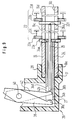
- FIG. 1 there is shown a similar embodiment as diagrametically illustrated in Fig. 9, with analogous components being designated by the same reference numbers as in Fig. 9, but increased by 100.
- the pivot levers 138 and 142 are one-arm pivot levers pivotally mounted at 140.
- an operating slide 146 For moving the pivot levers 138 and 142 there is provided an operating slide 146.
- This operating slide is provided with a control track 146a for the pivot lever 142 and with a control track 146b for the pivot lever 138.
- Both control tracks 146a and 146b are provided with a plurality of plateaus and slopes as shown in Fig. 2.
- the pivot lever 142 is engaged with the control track 146b by a track follower 142a.
- the pivot lever 138 is engaged with the control track 146a by a further track follower 138a which is covered in Fig. 2 by the track follower 142a.
- the pivot levers 138 and 142 are rocked about pivot axis 140 such as to axially move the control tube 134 and the control rod 136 within the hub shaft bore 16b, as more detailed shown in Fig. 9.
- the slide members 22e, 22f and the sun wheels 22a, 22b may be axially positioned at various locations by cooperation of the control tube 34 and the spring 22c and also by cooperation of the control rod 36 and the spring 22d.
- Figs. 1 and 2 also show a push-pull Bowden-cable 128' as described in more detail in Fig. 10.
- the socket 128 can be fastened on the hub shaft end 116a by a clamping screw 150.
- the control tube 134 is again provided with a slot 134d for allowing the pivot lever 142 to enter therein.
- the control tube is secured against rotation by an angular positioning nose 134n engaging into a guiding groove.
- FIGs. 3 and 4 there is shown a further embodiment.
- analogous parts are designated by the same reference numbers as in Figs. 1 and 2, but further increased by 100.
- pivot levers 238 and 242 are pivotally mounted about two pivot axes 240 1 and 240 2 , respectively. Moreover, both pivot levers 238 and 242 are two-arm pivot levers, so that the control tracks 246a and 246b are directed to the left in Fig. 3 in contradiction to Fig. 2, where the control tracks are directed to the right.
- the operating slide 246 is further provided with a detent track 246c which comprises five detent recesses 246c 1 to 246c 5 .
- a detent lever 254 of elastomeric material is fastened at 254a to the housing 227, as shwon in Fig. 4.
- This detent lever is spring loaded by a leaf- or wire-spring 256, which is also fastened to the housing 227.
- the detent lever 254 is biased toward engagement with the detent track 246c and can fall when moving the operating slide 246 in the direction 246d along the guide face 246e into respective detent recesses 246c 1 to 246c 5 .
- the operating slide 246 can be easily positioned into discrete longitudinal positions along the guide face 246. Such, one can also make sure that the control rod 236 and the control tube 234 are located in discrete positions along the hub shaft bore in assuming that the housing 227 is correctly fastened to the hub shaft 216. Thus, erroneous positions of the sun wheel 22a and 22b of Fig. 9 can be avoided.
- the correct positioning of the housing 227 with respect to the hub shaft 216 can be obtained by axial abutment at 17, as shown in Fig. 9.
- the handling mechanism 30, as shown in Fig. 10 may be continuously movable without the necessity of detent means.
- the embodiment of Figs. 1 and 2 is preferably used in combination with a handling mechanism 30, in which the lever 30a can be arrested in discrete angular positions.
- a base shell of the housing 227 in which the guide face 246 and the pivot bolts 240 1 and 240 2 may be integrally shaped as parts of the base shell.
- the base shell may be moulded of synthetic plastics material.
- a corresponding cover shell exists which may be fastened to the base shell by screwing, rivetting or ultra-sonic welding.
- the housing 227 is secured against entrance of dust and splashed water.
- the cavity defined within the housing 227 may be filled with lubricant which is prevented from exit, so a volume of lubricant may be included, which is sufficient for the expected lifetime of the operating mechanism.
- a Bowden-wire may also be used with pulling function only when it is combined with spring means biasing the operating slide in a direction against the pulling direction of the Bowden-wire.
- a slot in the control tube 234 may be avoided. It is easily understandable that such a slot, as shown at 134d in Fig. 2, may also be provided for avoiding interference of the pivot levers. In such case, it is again helpful, to prevent rotation of the control tube 234, at least in such cases, in which the lever 242 is movable inward and outward of the slot. For securing against rotation the control tube may be flattened.
- Fig. 5 there is shown in detail the allocation of which to the embodiment of Fig. 9 can be easily recognized by analogous reference numbers increased by 300 compared with Fig. 9.
- control rod 36 and the control tube 34 could be easily lost by an unintentional separation from the hub shaft 16. Such loss can be avoided by the embodiment as shown in Fig. 5.
- the control tube 334 has a left hand terminal flange 334f for the engagement with a pivot lever, as shown at 38 in Fig. 9, and the control rod 336 has a left hand terminal flange 336f for the engagement of a pivot lever corresponding to 42 in Fig. 9.
- the control rod 336 has an externally threaded section 336g and the slide member 322e has a corresponding internal thread 322e 1 .
- the control rod 336 is only in abutting engagement with the slide member 322f.
- control tube 334 Before inserting the control rod 336 and the control tube 334 into the hub shaft bore 16b, as shown in Fig. 9, from the left hand end of the hub shaft 16, one can slide the control tube 334 along the control rod 336, starting at the right hand end of the control rod 336, as shown in Fig. 5. This is possible because the external diameter of the externally threaded section 336g is smaller than the internal diameter of the control tube 334.
- the control tube 334 is axially positioned with respect to the control rod 336 such as shown in Fig. 5, the group consisting of the control rod 336 and the control tube 334 may be inserted into the hub shaft bore 16b, as shown in Fig. 9.
- FIGs. 7 and 8 A further embodiment is shown in Figs. 7 and 8. Analogous parts are designated by the same reference numbers as in Fig. 5, further increased by 100.
- Fig. 8 shows a slot 434d of the control tube 434. This slot corresponds as to location and function to the slot 34d in Fig. 9 and the slot 134d in Fig. 2.
- the control tube 434 is provided with flat side faces 434i and 434k for preventing rotation with respect to the hub shaft bore 16, as shown in Fig. 9.
- Fig. 6 shows a modification with respect to Fig. 9. Analogous parts are designated with the same reference numbers as shown in Fig. 9, but increased by 500.
- the end faces 536t and 534t of the control rod 536 and the control tube 534, respectively, are located inside the hub shaft bore 516b.
- the housing 527 is provided with a mover tube 560 and a mover rod 562 which abut against the control tube 534 and the control rod 536, respectively, at 534t and 536t.
- the mover tube 560 is secured against loss from the housing 527 by a securing projection 564 engagable with the housing wall at 568.
- the mover rod is secured against loss by a radial projection 570 engagable with an inner end of the slot 534d.
- Fig. 6 The embodiment of Fig. 6 is important: It is to be noted that both ends 536t and 534t are located inside the hub shaft 516. Such, nothing projects axially beyond the hub shaft 516. This is desirable when one wants to insert the hub as shown in Fig. 10 into an automatic spoke assembling machine for attaching the spokes 15 of Fig. 10 to the hub shell 14.
Landscapes
- Engineering & Computer Science (AREA)
- Chemical & Material Sciences (AREA)
- Combustion & Propulsion (AREA)
- Transportation (AREA)
- Mechanical Engineering (AREA)
- Gear-Shifting Mechanisms (AREA)
- Structure Of Transmissions (AREA)
- Steering Devices For Bicycles And Motorcycles (AREA)
- Transmission Devices (AREA)
- Automatic Cycles, And Cycles In General (AREA)
- Connection Of Motors, Electrical Generators, Mechanical Devices, And The Like (AREA)
Abstract
Description
- Fig. 1
- shows an end view of a first embodiment of an operating mechanism;
- Fig. 2
- shows a section according to line II-II of Fig. 1;
- Fig. 3
- shows a section analogous to the section of Fig. 2 with a second embodiment of an operating mechanism;
- Fig. 4
- shows a section according to Fig. 3 with the pivot levers being omitted for reasons of clarity;
- Fig. 5
- shows a detail, namely a combination of a first and a second speed change control member with allocated control slide members;
- Fig. 6
- shows in a diagrammatic way an operating mechanism in combination with a modified embodiment of a bicycle hub;
- Fig. 7
- shows a combination as shown in Fig. 5 with modified locking means between the speed change control members;
- Fig. 8
- shows a cross-sectional area of a tubular speed change control member;
- Fig. 9
- shows in a diagrammatic view the combination of an operating mechanism with a hub shaft and the abutting engagement between the speed change control members and the control slide members of the gear means with the loss-preventing means being omitted for sake of clarity and
- Fig. 10
- shows an overall view of a multi-speed bicycle hub partially in section with a rearward fork of a bicycle with an operating mechanism and with a handling mechanism connected to the operating mechanism by a Bowden cable with the loss-preventing means being omitted for sake of clarity.
Claims (30)
- A combination of a multi-speed bicycle hub (12) having a hub shaft (16) with a hub shaft axis, a hub sleeve (14) being rotatably mounted on said hub shaft (16) about said hub shaft axis, gear means (22) being accommodated within said hub sleeve (14), at least one driving wheel (18) being in driving connection with an input member (20) of said gear means (22), at least one output member (24) of said gear means (22) being in driving connection with said hub sleeve (14), said hub shaft (16) having an axially extending hub shaft bore (16b) open towards a hub shaft end (16a), said hub shaft bore (16b) accommodating at least two speed change control members (336,334) extending along said hub shaft bore (16b) and being in control connection with said gear means (22),
and of an operating mechanism (26) located adjacent said hub shaft end (16a), said operating mechanism (26) comprising respective mover units (42,38) operationally engageable with respective mover-side endportions (336f,334f) of respective speed change control members (336,334),
characterized in thatsaid at least two speed change control members (336,334) are secured against being lost before combining the hub (12) with the operating mechanism (26) bysaid first speed change control member (336) pushingly abutting a first control slide member (322f) of said gear means (322) more remote from said hub shaft end (16a),said second speed change control member (334) pushingly abutting a second control slide member (322e) of said gear means (322) nearer to said hub shaft end (16a), said first speed change control member (336) transversing passage means (322e2) across said second control slide member (322e), said first speed change control member (336) being provided with loss-preventing means (336g) manoeuverable through said passage means (322e2) in an axial direction of introduction of said first speed change control member (336) from said hub shaft end (16a) toward said first control slide member (322f),said loss-preventing means (336g) cooperating with return-preventing means located adjacent the inner side of said passage means (322e2) and preventing unintended return of said first speed change control member (336) outward of said hub shaft bore (16b),said first and said second speed change control member (336,334) being provided with respective locking means (336f,334f) abuttingly cooperating with each other and preventing withdrawal of said second speed change control member (334) out of said hub shaft bore (16b) in an axial direction opposite to said axial direction of introduction. - A combination as claimed in claim 1,
said first speed change control member (336) being a rod-like speed change control member (336) and said second speed change control member (334) being a tubular speed change control member (334) surrounding said first speed change control member (336). - A combination as claimed in claim 1 or 2,
said first speed change control member (336) having larger axial length than said second speed change control member (334). - A combination as claimed in one of claims 1 to 3,
said locking means (336f) of said first speed change control member (336) being provided axially outside of said mover side end portion (334f) of said second speed change control member (334) and said locking means (334f) of said second speed change control member (334) being provided adjacent said mover side end portion (334f) thereof. - A combination as claimed in claim 2,
said locking means (336f) of said rod-like first speed change control member (336) being provided by a locking head (336f) axially outside said mover side end portion (334f) of said second speed change control member (334), said locking means (334f) of said tubular second speed change control member (334) being provided by said mover side end portion (334f) thereof. - A combination as claimed in claim 2,
said locking means (437) of said rod-like first speed change control member (436) being provided by a thickened portion (437) thereof located inside said tubular second speed change control member (434), said locking means (435) of said tubular second speed change control member (434) being provided by an internally narrowed portion (435) thereof. - A combination as claimed in one of claims 2 to 6,
said loss-preventing means (336g) being provided by an externally threaded portion (336g) of said first speed change control member (336), said passage means (322e2) being provided with corresponding internal thread means (322e1). - A combination as claimed in claim 7,
said externally threaded portion (336g) being of enlarged diameter as compared with an adjacent section of said rod-like, first speed change control member (336). - A combination as claimed in one of claims 2 to 8,
said mover side end portions (534t,536t) of both said speed change control members (536,534) being located inside said hub shaft bore (516b), said mover units of a said operating mechanism comprising a mover rod (562) and a mover tube (560) surrounding said mover rod (562) for abutment with respective mover side end portions (536t,534t) of said rod-like first speed change control member (536) and said tubular second speed change control member (534) inside said hub shaft bore (516b). - A combination as claimed in claim 9,
said mover rod (562) and said mover tube (560) being secured with respect to said operating mechanism (526) against being lost. - A combination as claimed on one of claims 1 to 10,
said operating mechanism (126) comprising an operating slide (146) guided within a housing (127) of said operating mechanism (126), said operating slide (146) acting through respective control tracks (146a, 146b) on respective speed change control members (136,134). - A combination as claimed in claim 11,
said operating slide (146) being guided in a direction (146d) substantially perpendicular with respect to said hub shaft axis. - A combination as claimed in claim 11 or 12,
said operating slide (146) being connected to a handling mechanism (30) by transmission means (28). - A combination as claimed in claim 13,
said transmission means (28) being push-pull transmission means (28). - A combination as claimed in one of claims 11 to 14,
said control tracks (146a,146b) acting onto said speed change control members (136,134) through respective pivot levers (142,138) pivotally mounted with respect to said housing (127). - A combination as claimed in claim 15,
said pivot levers (142,138) being pivotally mounted about a pivot axis (140) substantially perpendicular to both said hub shaft axis and linear guiding means (146e) of said operating slide (146). - A combination as claimed in one of claims 11 to 16,
said control tracks (142,138) being integral with said operating slide (146). - A combination as claimed in one or claims 11 to 17,
said operating slide (246) being arrestable in individual speed positions by elastically acting arresting means (254,256,246c). - A combination as claimed in claim 18,
said arresting means (254,256,246c) comprising a detent track (246c) on said operating slide (246) and an elastically loaded detent member (254) engageable into individual detent recesses (246c1, ...,246c5) of said detent track (246c). - A combination as claimed in claim 19,
said detent member (254) being a detent lever (254). - A combination as claimed in one of claims 1 to 20,
said operating mechanism being substantially encapsulated by a housing (227). - A combination as claimed in claim 21,
said housing (227) being substantially tight against entrance of dust and splashed water. - A combination as claimed in claim 21 or 22,
said housing (227) being substantially tight against exit of lubricant. - A combination as claimed in one of claims 21 to 23,
said housing (227) being composed by housing shells made of synthetic plastics material. - A combination as claimed in claim 24,
mounting means (2401,2402) for movably mounting movable components (242,238,246) of said operating mechanism being integral with at least one of said housing shells. - A combination as claimed in one of claims 24 and 25,
said housing shells being fastened to each other by one of screw means, rivet means and ultrasonic welding seam means. - A combination as claimed in one of claims 2 to 26,
said tubular second speed change control member (34) being provided with a slot (34d) adjacent said mover side end portion thereof, said slot (34d) receiving a portion (42b) of a mover unit (42), for example, a pivot lever (42), acting onto said rod-like first speed change control member (36). - A combination as claimed in claim 27,
said portion (42b) of said mover unit (42) being part of a pivot lever (42), said pivot lever (42) being pivotally mounted substantially within a pivot plane containing said hub shaft axis. - A combination as claimed in one of claims 1 to 28,
first and second pivot levers (42,38) being shaped, respectively, for engagement with a control rod-like first speed change control member (36) and a tubular, second speed change control member (34) surrounding said first speed change control member (36). - A method of assembling a multi-speed bicycle hub (12) having a hub shaft (16) with a hub shaft axis, a hub sleeve (14) being rotatably mounted on said hub shaft (16) about said hub shaft axis, gear means (22) being accommodated within said hub sleeve (14), at least one driving wheel (18) being in driving connection with an input member (20) of said gear means (22), at least one output member (24) of said gear means (22) being in driving connection with said hub sleeve (14), said hub shaft (16) having an axially extending hub shaft bore (16b) open towards a hub shaft end (16a), said hub shaft bore (16b) accommodating at least two speed change control members (336,334) extending along said hub shaft bore (16b) and being in control connection with said gear means (22),
and of an operating mechanism (26) located adjacent said hub shaft end (16a), said operating mechanism (26) comprising respective mover units (42,38) operationally engageable with respective mover-side endportions (336f,334f) of respective speed change control members (336,334),
said method comprising fastening said operating mechanism (26) on said hub shaft end (16a) by inter-engageable fastening means of said hub shaft end (16a) and counter-fastening means (28) of said operating mechanism (26),
characterized in thatbefore combining said hub (12) with said operating mechanism (26) said at least two speed change control members (336,334) are inserted into the hub shaft bore (16b) and secured against being lost wherein the control members are inserted so that said first speed change control member (336) pushingly abuts a first control slide member (322f) of said gear means (322) more remote from said hub shaft end (16a), said second speed change control member (334) pushingly abuts a second control slide member (322e) of said gear means (322) nearer to said hub shaft end (16a), said first speed change control member (336) transversing passage means (322e2) across said second control slide member (322e), said first speed change control member (336) being provided with loss-preventing means (336g) which is manoeuvered through said passage means (322e2) in an axial direction of introduction of said first speed change control member (336) from said hub shaft end (16a) toward said first control slide member (322f),
said loss-preventing means (336g) then cooperating with return-preventing means located adjacent the inner side of said passage means (322e2) and preventing unintended return of said first speed change control member (336) outward of said hub shaft bore (16b),
said first and said second speed change control member (336,334) being provided with respective locking means (336f,334f) abuttingly cooperating with each other and preventing withdrawal of said second speed change control member (334) out of said hub shaft bore (16b) in an axial direction opposite to said axial direction of introduction.
Priority Applications (1)
| Application Number | Priority Date | Filing Date | Title |
|---|---|---|---|
| EP95102526A EP0661204B1 (en) | 1992-05-21 | 1993-05-19 | An operating mechanism for combination with a multi-speed bicycle hub |
Applications Claiming Priority (2)
| Application Number | Priority Date | Filing Date | Title |
|---|---|---|---|
| DE4216826 | 1992-05-21 | ||
| DE19924216826 DE4216826C2 (en) | 1992-05-21 | 1992-05-21 | Shift actuator for multi-speed hubs for bicycles or the like |
Related Child Applications (2)
| Application Number | Title | Priority Date | Filing Date |
|---|---|---|---|
| EP95102526A Division EP0661204B1 (en) | 1992-05-21 | 1993-05-19 | An operating mechanism for combination with a multi-speed bicycle hub |
| EP95102526.1 Division-Into | 1993-05-19 |
Publications (3)
| Publication Number | Publication Date |
|---|---|
| EP0570948A2 EP0570948A2 (en) | 1993-11-24 |
| EP0570948A3 EP0570948A3 (en) | 1993-12-29 |
| EP0570948B1 true EP0570948B1 (en) | 1998-10-28 |
Family
ID=6459423
Family Applications (2)
| Application Number | Title | Priority Date | Filing Date |
|---|---|---|---|
| EP95102526A Expired - Lifetime EP0661204B1 (en) | 1992-05-21 | 1993-05-19 | An operating mechanism for combination with a multi-speed bicycle hub |
| EP93108190A Expired - Lifetime EP0570948B1 (en) | 1992-05-21 | 1993-05-19 | A multi-speed bicycle hub and an operating mechanism thereof |
Family Applications Before (1)
| Application Number | Title | Priority Date | Filing Date |
|---|---|---|---|
| EP95102526A Expired - Lifetime EP0661204B1 (en) | 1992-05-21 | 1993-05-19 | An operating mechanism for combination with a multi-speed bicycle hub |
Country Status (4)
| Country | Link |
|---|---|
| US (1) | US5469755A (en) |
| EP (2) | EP0661204B1 (en) |
| AT (2) | ATE156440T1 (en) |
| DE (3) | DE4244679C2 (en) |
Families Citing this family (6)
| Publication number | Priority date | Publication date | Assignee | Title |
|---|---|---|---|---|
| DE29608010U1 (en) * | 1996-05-03 | 1996-07-25 | Fichtel & Sachs Ag | Housing for an operating cable for switching the gear stages of a bicycle transmission |
| JP3142247B2 (en) * | 1997-05-08 | 2001-03-07 | 株式会社シマノ | Interior gear hub for bicycle |
| CN1118411C (en) * | 1999-12-30 | 2003-08-20 | 株式会社岛野 | Bell crank mounting bracket for bicycle hub transmission |
| DE10026472A1 (en) * | 2000-05-27 | 2001-11-29 | Sram De Gmbh | Shift control for multi-speed hubs for bicycles |
| EP1388491B1 (en) | 2002-08-08 | 2009-09-30 | SRAM Deutschland GmbH | Cable connection |
| DE102006010874A1 (en) * | 2006-03-07 | 2007-09-27 | Sram Deutschland Gmbh | Linkage coupling for bicycle, has hook part including recess and/or insertion opening for stepping through insertion in radial direction and/or transverse to rope direction, and guidance section provided for guiding insertion |
Family Cites Families (12)
| Publication number | Priority date | Publication date | Assignee | Title |
|---|---|---|---|---|
| GB424814A (en) * | 1934-08-25 | 1935-02-28 | Charles Randall Little | Flexible push-and-pull control mechanism |
| DE673303C (en) * | 1934-11-01 | 1939-03-20 | Jean Kuehlwein | Double sprocket change gear for bicycles with freewheel |
| DE1092333B (en) * | 1958-07-05 | 1960-11-03 | Fichtel & Sachs Ag | Adjustment device for gear hubs of bicycles or the like. |
| US3021728A (en) * | 1958-07-22 | 1962-02-20 | Shimano Keizo | Three stage speed change mechanism for a bicycle |
| DE1166027B (en) * | 1960-12-10 | 1964-03-19 | Fichtel & Sachs Ag | Switching device for multi-speed hubs |
| US3244212A (en) * | 1964-11-18 | 1966-04-05 | South Chester Corp | Retractable threaded fastener |
| JPS52129131A (en) * | 1976-04-21 | 1977-10-29 | Shimano Industrial Co | Internal transmission |
| DE3314229A1 (en) * | 1983-04-20 | 1984-10-25 | Fichtel & Sachs Ag, 8720 Schweinfurt | Gear-shift device for multi-speed hub gear for bicycles or the like |
| DE3440066A1 (en) * | 1984-11-02 | 1986-05-07 | Fichtel & Sachs Ag, 8720 Schweinfurt | Gear-shift device for multi-speed gear hub for cycles or the like |
| DE3823385A1 (en) * | 1988-07-09 | 1990-01-11 | Fichtel & Sachs Ag | SHIFTING DEVICE FOR MULTI-SPEED HUBS FOR BICYCLES OR THE LIKE |
| DE3930374A1 (en) * | 1988-10-10 | 1990-04-12 | Fichtel & Sachs Ag | MULTI-SPEED DRIVE HUB WITH MORE THAN THREE GEARS |
| DE4005102A1 (en) * | 1990-02-17 | 1991-09-05 | Armin Beck | Bicycle change-speed selector lever - actuates both front and rear changeover devices using CAM mechanism |
-
1992
- 1992-05-21 DE DE4244679A patent/DE4244679C2/en not_active Expired - Fee Related
-
1993
- 1993-05-19 AT AT95102526T patent/ATE156440T1/en not_active IP Right Cessation
- 1993-05-19 EP EP95102526A patent/EP0661204B1/en not_active Expired - Lifetime
- 1993-05-19 DE DE69312944T patent/DE69312944T2/en not_active Expired - Lifetime
- 1993-05-19 DE DE69321761T patent/DE69321761T2/en not_active Expired - Fee Related
- 1993-05-19 US US08/063,930 patent/US5469755A/en not_active Expired - Fee Related
- 1993-05-19 AT AT93108190T patent/ATE172678T1/en not_active IP Right Cessation
- 1993-05-19 EP EP93108190A patent/EP0570948B1/en not_active Expired - Lifetime
Also Published As
| Publication number | Publication date |
|---|---|
| ATE156440T1 (en) | 1997-08-15 |
| EP0570948A2 (en) | 1993-11-24 |
| EP0661204A1 (en) | 1995-07-05 |
| DE4244679A1 (en) | 1994-05-05 |
| DE69312944D1 (en) | 1997-09-11 |
| DE69312944T2 (en) | 1997-12-11 |
| ATE172678T1 (en) | 1998-11-15 |
| DE69321761D1 (en) | 1998-12-03 |
| DE4244679C2 (en) | 1996-02-08 |
| EP0570948A3 (en) | 1993-12-29 |
| DE69321761T2 (en) | 1999-04-01 |
| EP0661204B1 (en) | 1997-08-06 |
| US5469755A (en) | 1995-11-28 |
Similar Documents
| Publication | Publication Date | Title |
|---|---|---|
| US4889521A (en) | Multistage sprocket assembly for a bicycle | |
| EP0661204B1 (en) | An operating mechanism for combination with a multi-speed bicycle hub | |
| EP1312813B1 (en) | Protective cap system for bicycle cable | |
| EP0790177B1 (en) | Bar-end shifting device | |
| US20080133096A1 (en) | Electronically servo-assisted bicycle gearshift and related method | |
| US5468197A (en) | Shift rail position sensor for vehicle transmission | |
| US4630702A (en) | Three-wheeled motor vehicle gear shift mechanism | |
| EP0020092A2 (en) | Cycle derailleur | |
| US4494419A (en) | Transmission mechanism in a manual transmission | |
| US4065984A (en) | Internally accommodated speed change mechanism applicable to a bicycle | |
| US4676118A (en) | Speed change mechanism for a bicycle | |
| EP1262691B1 (en) | Manual transmission | |
| DE69402101D1 (en) | Gear shift device for an automatic motor vehicle transmission | |
| US5392668A (en) | Actuating means for a multispeed cycle hub | |
| CN106246906A (en) | Universal operating device for overdrive gearbox and application method thereof | |
| EP0297263B1 (en) | A pre-assembled drive transmission device for transmitting drive between parallel axes | |
| KR102495149B1 (en) | Rotary type transmission for vehicle | |
| CA1206069A (en) | Connecting element for linkages, especially automotive gearshift linkages | |
| WO1999020519A1 (en) | Automatic transmission for bicycle | |
| JPS58203257A (en) | belt drive device | |
| JP3464576B2 (en) | Assembling method of transmission striking lever and transmission | |
| GR82330B (en) | ||
| KR970008496B1 (en) | Transmission of car manual transmission | |
| CA1192812A (en) | Decoupling device for gearshift linkages | |
| KR970003218Y1 (en) | Gear speed change tube for sound-proofing and discharge of manual transmission gear box |
Legal Events
| Date | Code | Title | Description |
|---|---|---|---|
| PUAI | Public reference made under article 153(3) epc to a published international application that has entered the european phase |
Free format text: ORIGINAL CODE: 0009012 |
|
| PUAL | Search report despatched |
Free format text: ORIGINAL CODE: 0009013 |
|
| AK | Designated contracting states |
Kind code of ref document: A2 Designated state(s): AT DE GB NL SE |
|
| AK | Designated contracting states |
Kind code of ref document: A3 Designated state(s): AT DE GB NL SE |
|
| 17P | Request for examination filed |
Effective date: 19940318 |
|
| 17Q | First examination report despatched |
Effective date: 19941212 |
|
| RAP1 | Party data changed (applicant data changed or rights of an application transferred) |
Owner name: MANNESMANN SACHS AKTIENGESELLSCHAFT |
|
| GRAG | Despatch of communication of intention to grant |
Free format text: ORIGINAL CODE: EPIDOS AGRA |
|
| GRAG | Despatch of communication of intention to grant |
Free format text: ORIGINAL CODE: EPIDOS AGRA |
|
| GRAG | Despatch of communication of intention to grant |
Free format text: ORIGINAL CODE: EPIDOS AGRA |
|
| GRAH | Despatch of communication of intention to grant a patent |
Free format text: ORIGINAL CODE: EPIDOS IGRA |
|
| GRAH | Despatch of communication of intention to grant a patent |
Free format text: ORIGINAL CODE: EPIDOS IGRA |
|
| RAP1 | Party data changed (applicant data changed or rights of an application transferred) |
Owner name: SRAM DEUTSCHLAND GMBH |
|
| GRAA | (expected) grant |
Free format text: ORIGINAL CODE: 0009210 |
|
| AK | Designated contracting states |
Kind code of ref document: B1 Designated state(s): AT DE GB NL SE |
|
| DX | Miscellaneous (deleted) | ||
| REF | Corresponds to: |
Ref document number: 172678 Country of ref document: AT Date of ref document: 19981115 Kind code of ref document: T |
|
| REF | Corresponds to: |
Ref document number: 69321761 Country of ref document: DE Date of ref document: 19981203 |
|
| PG25 | Lapsed in a contracting state [announced via postgrant information from national office to epo] |
Ref country code: AT Free format text: LAPSE BECAUSE OF NON-PAYMENT OF DUE FEES Effective date: 19990519 |
|
| PLBE | No opposition filed within time limit |
Free format text: ORIGINAL CODE: 0009261 |
|
| 26N | No opposition filed | ||
| REG | Reference to a national code |
Ref country code: GB Ref legal event code: IF02 |
|
| PGFP | Annual fee paid to national office [announced via postgrant information from national office to epo] |
Ref country code: DE Payment date: 20080530 Year of fee payment: 16 |
|
| PGFP | Annual fee paid to national office [announced via postgrant information from national office to epo] |
Ref country code: NL Payment date: 20080515 Year of fee payment: 16 Ref country code: SE Payment date: 20080513 Year of fee payment: 16 |
|
| PGFP | Annual fee paid to national office [announced via postgrant information from national office to epo] |
Ref country code: GB Payment date: 20080522 Year of fee payment: 16 |
|
| GBPC | Gb: european patent ceased through non-payment of renewal fee |
Effective date: 20090519 |
|
| NLV4 | Nl: lapsed or anulled due to non-payment of the annual fee |
Effective date: 20091201 |
|
| PG25 | Lapsed in a contracting state [announced via postgrant information from national office to epo] |
Ref country code: NL Free format text: LAPSE BECAUSE OF NON-PAYMENT OF DUE FEES Effective date: 20091201 |
|
| PG25 | Lapsed in a contracting state [announced via postgrant information from national office to epo] |
Ref country code: GB Free format text: LAPSE BECAUSE OF NON-PAYMENT OF DUE FEES Effective date: 20090519 |
|
| PG25 | Lapsed in a contracting state [announced via postgrant information from national office to epo] |
Ref country code: DE Free format text: LAPSE BECAUSE OF NON-PAYMENT OF DUE FEES Effective date: 20091201 |
|
| PG25 | Lapsed in a contracting state [announced via postgrant information from national office to epo] |
Ref country code: SE Free format text: LAPSE BECAUSE OF NON-PAYMENT OF DUE FEES Effective date: 20090520 |