EP0570905B1 - Fuel assembly with debris catcher for a light-water nuclear reactor - Google Patents
Fuel assembly with debris catcher for a light-water nuclear reactor Download PDFInfo
- Publication number
- EP0570905B1 EP0570905B1 EP93108070A EP93108070A EP0570905B1 EP 0570905 B1 EP0570905 B1 EP 0570905B1 EP 93108070 A EP93108070 A EP 93108070A EP 93108070 A EP93108070 A EP 93108070A EP 0570905 B1 EP0570905 B1 EP 0570905B1
- Authority
- EP
- European Patent Office
- Prior art keywords
- fuel assembly
- debris catcher
- debris
- tie plate
- fuel
- Prior art date
- Legal status (The legal status is an assumption and is not a legal conclusion. Google has not performed a legal analysis and makes no representation as to the accuracy of the status listed.)
- Expired - Lifetime
Links
Images


Classifications
-
- G—PHYSICS
- G21—NUCLEAR PHYSICS; NUCLEAR ENGINEERING
- G21C—NUCLEAR REACTORS
- G21C3/00—Reactor fuel elements and their assemblies; Selection of substances for use as reactor fuel elements
- G21C3/30—Assemblies of a number of fuel elements in the form of a rigid unit
- G21C3/32—Bundles of parallel pin-, rod-, or tube-shaped fuel elements
- G21C3/3206—Means associated with the fuel bundle for filtering the coolant, e.g. nozzles, grids
-
- G—PHYSICS
- G21—NUCLEAR PHYSICS; NUCLEAR ENGINEERING
- G21C—NUCLEAR REACTORS
- G21C3/00—Reactor fuel elements and their assemblies; Selection of substances for use as reactor fuel elements
- G21C3/30—Assemblies of a number of fuel elements in the form of a rigid unit
- G21C3/32—Bundles of parallel pin-, rod-, or tube-shaped fuel elements
-
- Y—GENERAL TAGGING OF NEW TECHNOLOGICAL DEVELOPMENTS; GENERAL TAGGING OF CROSS-SECTIONAL TECHNOLOGIES SPANNING OVER SEVERAL SECTIONS OF THE IPC; TECHNICAL SUBJECTS COVERED BY FORMER USPC CROSS-REFERENCE ART COLLECTIONS [XRACs] AND DIGESTS
- Y02—TECHNOLOGIES OR APPLICATIONS FOR MITIGATION OR ADAPTATION AGAINST CLIMATE CHANGE
- Y02E—REDUCTION OF GREENHOUSE GAS [GHG] EMISSIONS, RELATED TO ENERGY GENERATION, TRANSMISSION OR DISTRIBUTION
- Y02E30/00—Energy generation of nuclear origin
- Y02E30/30—Nuclear fission reactors
Definitions
- the invention relates to a fuel assembly for a light-water nuclear reactor according to the precharacterising part of claim 1.
- the debris may enter and then move with the water which circulates through the reactor core.
- the debris may, inter alia, consist of metal shavings (borings or turnings) formed in connection with the repair of, for example, a steam separator, pieces of metal wire, or other foreign particles, which have entered the system from the outside.
- the debris may give rise to abrasion damage, which may have serious consequences if it occurs on parts which are particularly easily damaged, such as fuel rods. This may be the case if the debris adheres to a spacer.
- bottom tie plates already existing under fuel rod bundles, with a large number of bored holes in order for each bottom tie plate, besides its normal function, to function as a debris catcher in the form of a strainer and prevent debris from reaching the fuel rod bundle with control rod guide tubes and spacers.
- bottom tie plate which is also intended to serve as a debris catcher is described in SE-A-91 00 402-8.
- This bottom tie plate is provided with horizontal channels which cross vertical flow channels, and in at least some of the horizontal channels spiral springs with horizontal symmetry axis are arranged.
- the disadvantage of this solution is that it is difficult to avoid that the flow resistance across the bottom tie plate becomes too high.
- a type of separate debris catcher arranged below the bottom tie plate is described in SE-B-465 644.
- This debris catcher comprises several turns of a wound tape or several concentric rings with spacing elements arranged between the turns of the tape or the rings, which spacing elements maintain a mutual distance between the turns of the tape or the rings in the radial direction.
- the problem with hitherto known separate debris catchers is that they provide an impermissibly high flow resistance and/or are complicated and expensive to manufacture.
- the invention aims at developing a fuel assembly for a light-water nuclear reactor with debris catcher means which is simple in design and does not massively increase the flow resistance through the fuel assembly.
- the invention suggests a fuel assembly for a light-water nuclear reactor according to the introductory part of claim 1, which is characterized by the features of the characterizing part of claim 1.
- the debris catcher is arranged as a separate unit below the bottom tie plate and spaced from this plate in the flow path of the water through the bundle of rods.
- the debris-catching elements of the debris catcher consist of springs, preferably helical springs. The use of helical springs as debris-catching elements allows an area reduction which is small in cross section and hence a moderate speed variation of the coolant flow when passing through the debris filter.
- a frame comprising two ends and a number of pins keep the springs in position. These ends consist of substantially parallel plates, the flat sides of which are interconnected via the pins.
- the pins are arranged spaced from each other in at least two rows between the ends in such a way that a plurality of parallel springs in spaced relationship or adjacent to each other can be fixed between the rows of pins in one or more layers.
- the debris catcher is normally arranged at least substantially such that the symmetry axis of the springs is horizontal. In a boiling water reactor, the debris catcher can be arranged spaced from the bottom tie plate.
- the debris catcher may be necessary to allow the debris catcher to make contact with the underside of the bottom tie plate or to arrange it at a very small distance from the underside.
- the debris catcher By designing the debris catcher in the manner described above, it may be given a very low flow resistance and hence constitute a minimal obstacle to the desired flow while at the same time the pins with intermediate springs are active during the debris catching.
- the flow holes in the bottom tie plate may be made somewhat larger.
- One advantage with the invention is that the debris catcher can be inserted into fuel assemblies without necessitating any major modifications and without significantly influencing the flow resistance.
- Another advantage in the mentioned case is that it is possible, in a simple manner, to supplement already existing fuel designs with debris catcher.
- a debris catcher according to the invention is very simple to manufacture and very robust since it can be designed with few parts. This also means that the risk of small parts becoming detached in connection with the water flowing through is very small.
- Figures 1-4 show a fuel channel 1 of substantially square cross section.
- the fuel channel 1 surrounds, with no significant free space, an upper square portion 2a of a bottom part 2 which otherwise comprises a conical portion 2b and a cylindrical portion 2c.
- the bottom part 2 has a downwardly-facing inlet opening 3 for cooling water.
- the bottom part 2 supports a supporting plate 4.
- the fuel channel 1 has a relatively thick wall portion which is fixed to the bottom part 2 and the supporting plate 4 by means of a plurality of horizontal bolts, indicated by dash-dotted lines 5.
- the fuel channel 1 is divided into four vertical tubular parts 6 with at least substantially square cross section.
- the supporting member 7 is welded to the four walls 1a, 1b, 1c and 1d of the fuel channel 1 and has four hollow wings 8.
- the central channel 32 formed by the supporting member 7 is connected at the bottom to an inlet tube 9 for moderator water.
- Each tubular part 6 comprises a bundle 25 of twenty-five fuel rods 10.
- the rods 10 are arranged in a symmetrical lattice in five rows each containing five rods 10.
- Each rod 10 is included in two rows perpendicular to each other.
- Each bundle 25 is arranged with a bottom tie plate 11, a top tie plate 12 and a plurality of spacers 13.
- a fuel rod bundle 25 with bottom tie plate 11, top tie plate 12, spacer 13 and fuel channel 1 forms a unit which, in this application, is referred to as a sub-assembly, whereas the device illustrated in Figures 1-4 and comprising four such sub-assemblies is referred to as a fuel assembly.
- the four bottom tie plates 11 are supported in the fuel assembly by the supporting plate 4 and are each partially inserted into a corresponding square hole 14 therein.
- at least one of the fuel rods 10 is made with relatively long, threaded end plugs 33 and 34 of solid cladding material, the lower end plug 33 being passed through the bottom tie plate 11 and provided with a nut 15, and the upper end plug 34 being passed through the top tie plate 12 and provided with a nut 16.
- the centre rod (26) in each sub-assembly is formed in this way. This rod also serves as a spacer holder rod.
- the holes for the passage of the water through the bottom tie plate 11 are designated 35.
- An upper end portion of the fuel channel 1 surrounds a cruciform lifting plate 17 with four horizontal arms 18, 19, 20 and 21, which emanate from a common central portion. At its outer end each arm 18-21 has an arrow-head-like portion 22, each of which makes contact with the inner wall surface of the fuel channel 1 at a respective corner of the fuel channel 1.
- a lifting handle 23 is fixed to the arms 18-21.
- the lifting plate 17 and the handle 23 together form a lifting member of steel cast in one piece.
- the lifting plate 17 is fixed to the supporting member 7 by inserting each of four vertical bars 28 into a respective wing 8 of the supporting member 7 and welding them thereto.
- each bar 28 has a vertical, bolt-like portion 29 which is passed, with a free space, through a corresponding hole in the central portion of the lifting plate 17 and provided with a nut 30.
- the fuel channel 1 is provided with indentations 31, arranged intermittently in the longitudinal direction, to which the supporting member 7 is welded.
- the debris catcher 36 is arranged below the bottom tie plates 11 in the bottom part 2, that is, in the flow path for the water which flows to each one of the bottom tie plates 11.
- the debris catcher 36 is best illustrated in Figures 4-6.
- Four debris catchers of the type shown in Figure 5 are arranged in a fuel assembly according to Figure 4.
- each debris catcher comprises two ends 37, 38 in the form of substantially parallel plates.
- the flat sides of the end plates 37, 38 are interconnected via pins 39.
- the pins 39 are arranged in spaced relationship in two rows between the end plates 37, 38 in such a way that a plurality of parallel helical springs 40, in spaced relationship to each other or placed adjacent to each other, can be fixed between the two rows of pins 39.
- One of the end plates 37 is provided with a peg 41 and the other end plate 38 with two pegs 42, these pegs allowing the debris catcher to be fixed to the bottom part 2.
- the two pegs 42 can suitably consist of pins 39 extending through end plate 38 .
- One of the end plates 37 can also be provided with a flange 43 which can be welded to the bottom part 2 for additional fixing of the debris catcher 36.
- the shape of the bottom part 2 necessitates bending of one (37) of the end plates 37,38 to accommodate the debris catcher.
- the whole debris catcher 36 can be made shorter, that is, the length of all the pins 39 and the springs 40 be shortened, but in that case the debris-catching area is reduced.
- the material in the end plates 37, 38 and the pins 39 consists, for example, of stainless steel or of any other material which is corrosion-resistant to the reactor water.
- the material in the springs 40 preferably consists of inconel.
- the pitch of the helical springs 40 is determined by the demands on the debris-catching capacity.
- the helical springs 40 are manufactured with tolerances which prevent the occurrence of a free space between the springs 40 and the pins 39, which eliminates the risk of abrasion because of vibrations.
- the diameter of the flow holes 35 in the bottom tie plate 11 may be increased somewhat.
- the debris catcher 36 consists of a device parallel to the bottom tie plate 11 in such a way that the symmetry axis of the helical springs 40 is horizontal. If the debris catcher 36 is arranged below the bottom tie plate 11, it has, in addition to the advantages mentioned above, the advantage of being able to be inspected and cleaned.
- a debris catcher 36 of the kind described can be used in a fuel assembly which is not, as in the exemplified case, divided into sub-assemblies with their own bottom tie plates 11 but which comprises only one single fuel rod bundle and one single bottom tie plate and is thus in analogous manner placed in the flow path of the water to the single bottom tie plate.
- a debris catcher 36 of the kind described can be arranged below the bottom tie plate of a pressurized-water reactor.
- a pressurized-water reactor because of the constructive design of the flow path of the water to the bottom tie plate, it is normally most suitable to allow the debris catcher 36 to make contact with the underside of the bottom tie plate.
Description
- The invention relates to a fuel assembly for a light-water nuclear reactor according to the precharacterising part of
claim 1. - Experience shows that, for example in connection with repairs and service of a nuclear reactor, debris may enter and then move with the water which circulates through the reactor core. The debris may, inter alia, consist of metal shavings (borings or turnings) formed in connection with the repair of, for example, a steam separator, pieces of metal wire, or other foreign particles, which have entered the system from the outside. The debris may give rise to abrasion damage, which may have serious consequences if it occurs on parts which are particularly easily damaged, such as fuel rods. This may be the case if the debris adheres to a spacer.
- To avoid damage of the above-mentioned kind in pressurized water reactors, it is known to form the bottom tie plates, already existing under fuel rod bundles, with a large number of bored holes in order for each bottom tie plate, besides its normal function, to function as a debris catcher in the form of a strainer and prevent debris from reaching the fuel rod bundle with control rod guide tubes and spacers.
- A type of bottom tie plate which is also intended to serve as a debris catcher is described in SE-A-91 00 402-8. This bottom tie plate is provided with horizontal channels which cross vertical flow channels, and in at least some of the horizontal channels spiral springs with horizontal symmetry axis are arranged. The disadvantage of this solution is that it is difficult to avoid that the flow resistance across the bottom tie plate becomes too high.
- A type of separate debris catcher arranged below the bottom tie plate is described in SE-B-465 644. This debris catcher comprises several turns of a wound tape or several concentric rings with spacing elements arranged between the turns of the tape or the rings, which spacing elements maintain a mutual distance between the turns of the tape or the rings in the radial direction. The problem with hitherto known separate debris catchers is that they provide an impermissibly high flow resistance and/or are complicated and expensive to manufacture.
- The invention aims at developing a fuel assembly for a light-water nuclear reactor with debris catcher means which is simple in design and does not massively increase the flow resistance through the fuel assembly.
- To achieve this aim the invention suggests a fuel assembly for a light-water nuclear reactor according to the introductory part of
claim 1, which is characterized by the features of the characterizing part ofclaim 1. - Further developments of the invention are characterized by the features of the additional claims.
- Preferably, the debris catcher is arranged as a separate unit below the bottom tie plate and spaced from this plate in the flow path of the water through the bundle of rods. The debris-catching elements of the debris catcher consist of springs, preferably helical springs. The use of helical springs as debris-catching elements allows an area reduction which is small in cross section and hence a moderate speed variation of the coolant flow when passing through the debris filter.
- A frame comprising two ends and a number of pins keep the springs in position. These ends consist of substantially parallel plates, the flat sides of which are interconnected via the pins. The pins are arranged spaced from each other in at least two rows between the ends in such a way that a plurality of parallel springs in spaced relationship or adjacent to each other can be fixed between the rows of pins in one or more layers.
- The debris catcher is normally arranged at least substantially such that the symmetry axis of the springs is horizontal. In a boiling water reactor, the debris catcher can be arranged spaced from the bottom tie plate.
- In at least certain types of pressurized water reactors, it may be necessary to allow the debris catcher to make contact with the underside of the bottom tie plate or to arrange it at a very small distance from the underside.
- By designing the debris catcher in the manner described above, it may be given a very low flow resistance and hence constitute a minimal obstacle to the desired flow while at the same time the pins with intermediate springs are active during the debris catching.
- To compensate for the pressure drop which the debris catcher still causes, the flow holes in the bottom tie plate may be made somewhat larger.
- One advantage with the invention is that the debris catcher can be inserted into fuel assemblies without necessitating any major modifications and without significantly influencing the flow resistance.
- Another advantage in the mentioned case is that it is possible, in a simple manner, to supplement already existing fuel designs with debris catcher.
- A debris catcher according to the invention is very simple to manufacture and very robust since it can be designed with few parts. This also means that the risk of small parts becoming detached in connection with the water flowing through is very small.
- By way of example, the invention will now be described in greater detail with reference to the accompanying drawings showing in
- Figure 1,
- in a vertical section along line I-I in Figure 2, an embodiment of a fuel assembly composed of four fuel rod bundles for a boiling-water reactor according to the invention with a debris catcher arranged below the bottom tie plate on each fuel rod bundle (sub-assembly),
- Figure 2
- the fuel assembly in Figure 1 contemplated from above (from Line II-II),
- Figure 3
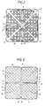
- a horizontal section along line III-III in Figure 1,
- Figure 4
- a view from above of four debris catchers according to Figure 1 arranged in the bottom part of a fuel assembly,
- Figure 5
- a debris catcher included in the fuel assembly according to Figure 1 in a view from above,
- Figure 6
- the debris catcher of Figure 5 in side elevation.
- Figures 1-4 show a
fuel channel 1 of substantially square cross section. Thefuel channel 1 surrounds, with no significant free space, an upper square portion 2a of abottom part 2 which otherwise comprises aconical portion 2b and acylindrical portion 2c. Thebottom part 2 has a downwardly-facing inlet opening 3 for cooling water. Besides supporting thefuel channel 1, thebottom part 2 supports a supportingplate 4. At its lowermost part, thefuel channel 1 has a relatively thick wall portion which is fixed to thebottom part 2 and the supportingplate 4 by means of a plurality of horizontal bolts, indicated by dash-dottedlines 5. - By means of a hollow supporting
member 7 with cruciform cross section, thefuel channel 1 is divided into four verticaltubular parts 6 with at least substantially square cross section. The supportingmember 7 is welded to the fourwalls fuel channel 1 and has fourhollow wings 8. Thecentral channel 32 formed by the supportingmember 7 is connected at the bottom to an inlet tube 9 for moderator water. Eachtubular part 6 comprises abundle 25 of twenty-fivefuel rods 10. Therods 10 are arranged in a symmetrical lattice in five rows each containing fiverods 10. Eachrod 10 is included in two rows perpendicular to each other. - Each
bundle 25 is arranged with abottom tie plate 11, atop tie plate 12 and a plurality ofspacers 13. Afuel rod bundle 25 withbottom tie plate 11,top tie plate 12,spacer 13 andfuel channel 1 forms a unit which, in this application, is referred to as a sub-assembly, whereas the device illustrated in Figures 1-4 and comprising four such sub-assemblies is referred to as a fuel assembly. - The four
bottom tie plates 11 are supported in the fuel assembly by the supportingplate 4 and are each partially inserted into a correspondingsquare hole 14 therein. In each sub-assembly at least one of thefuel rods 10 is made with relatively long, threadedend plugs lower end plug 33 being passed through thebottom tie plate 11 and provided with anut 15, and theupper end plug 34 being passed through thetop tie plate 12 and provided with anut 16. In the embodiment shown the centre rod (26) in each sub-assembly is formed in this way. This rod also serves as a spacer holder rod. - The holes for the passage of the water through the
bottom tie plate 11 are designated 35. An upper end portion of thefuel channel 1 surrounds acruciform lifting plate 17 with fourhorizontal arms like portion 22, each of which makes contact with the inner wall surface of thefuel channel 1 at a respective corner of thefuel channel 1. Alifting handle 23 is fixed to the arms 18-21. Thelifting plate 17 and thehandle 23 together form a lifting member of steel cast in one piece. The liftingplate 17 is fixed to the supportingmember 7 by inserting each of fourvertical bars 28 into arespective wing 8 of the supportingmember 7 and welding them thereto. At the top eachbar 28 has a vertical, bolt-like portion 29 which is passed, with a free space, through a corresponding hole in the central portion of the liftingplate 17 and provided with anut 30. As will be clear from the figures, thefuel channel 1 is provided withindentations 31, arranged intermittently in the longitudinal direction, to which the supportingmember 7 is welded. - According to the invention the
debris catcher 36 is arranged below thebottom tie plates 11 in thebottom part 2, that is, in the flow path for the water which flows to each one of thebottom tie plates 11. Thedebris catcher 36 is best illustrated in Figures 4-6. Four debris catchers of the type shown in Figure 5 are arranged in a fuel assembly according to Figure 4. - In Figures 1, 4, 5 and 6 each debris catcher comprises two ends 37, 38 in the form of substantially parallel plates. The flat sides of the
end plates pins 39 are arranged in spaced relationship in two rows between theend plates helical springs 40, in spaced relationship to each other or placed adjacent to each other, can be fixed between the two rows ofpins 39. - One of the
end plates 37 is provided with apeg 41 and theother end plate 38 with twopegs 42, these pegs allowing the debris catcher to be fixed to thebottom part 2. The two pegs 42 can suitably consist ofpins 39 extending throughend plate 38 . One of theend plates 37 can also be provided with aflange 43 which can be welded to thebottom part 2 for additional fixing of thedebris catcher 36. - The shape of the
bottom part 2 necessitates bending of one (37) of theend plates whole debris catcher 36 can be made shorter, that is, the length of all thepins 39 and thesprings 40 be shortened, but in that case the debris-catching area is reduced. - The material in the
end plates pins 39 consists, for example, of stainless steel or of any other material which is corrosion-resistant to the reactor water. The material in thesprings 40 preferably consists of inconel. The pitch of thehelical springs 40 is determined by the demands on the debris-catching capacity. The helical springs 40 are manufactured with tolerances which prevent the occurrence of a free space between thesprings 40 and thepins 39, which eliminates the risk of abrasion because of vibrations. - To compensate for the pressure drop which arises across the
debris catcher 36, the diameter of the flow holes 35 in thebottom tie plate 11 may be increased somewhat. - According to a particularly preferred embodiment of the invention, the
debris catcher 36 consists of a device parallel to thebottom tie plate 11 in such a way that the symmetry axis of thehelical springs 40 is horizontal. If thedebris catcher 36 is arranged below thebottom tie plate 11, it has, in addition to the advantages mentioned above, the advantage of being able to be inspected and cleaned. - It is obvious that a
debris catcher 36 of the kind described can be used in a fuel assembly which is not, as in the exemplified case, divided into sub-assemblies with their ownbottom tie plates 11 but which comprises only one single fuel rod bundle and one single bottom tie plate and is thus in analogous manner placed in the flow path of the water to the single bottom tie plate. - It is also obvious that a
debris catcher 36 of the kind described can be arranged below the bottom tie plate of a pressurized-water reactor. In a pressurized-water reactor, because of the constructive design of the flow path of the water to the bottom tie plate, it is normally most suitable to allow thedebris catcher 36 to make contact with the underside of the bottom tie plate.
Claims (5)
- Fuel assembly for a light-water nuclear reactor comprising a plurality of vertical fuel rods (10) which are arranged, in spaced relationship, between at least one bottom tie plate (11) and at least one top tie plate (12) each being provided with through-holes (35) for inlet and outlet of coolant, and comprising a substantially horizontally arranged debris catcher (36) below the bottom tie plate in the flow path of the water, characterized in that said debris catcher comprises at least two end plates (37,38) arranged with their large sides substantially vertically and substantially parallel to each other, a plurality of pins (39) extending parallel to one another between said end plates in at least two vertically spaced rows, and a plurality of longitudinal springs extending also in parallel with one another and between said pins and between said end plates, the spacing between any two adjacent pins in both the vertical direction and the horizontal direction being less than the diameter of any spring so as to maintain each spring in its desired position.
- Fuel assembly according to claim 1, characterized in that the springs (40) are arranged in one or more layers.
- Fuel assembly according to any claim 1 or 2, characterized in that the springs (40) are of helical type.
- Fuel assembly according to any of the preceding claims, characterized in that at least one of the end plates (37,38) in the debris catcher (36) is provided with at least one peg (41,42) by means of which the debris catcher is fixed to the bottom part (2) of the fuel assembly.
- Fuel assembly according to any of the preceding claims, characterized in that the debris catcher (36) is arranged in spaced relationship to the bottom tie plate (11).
Applications Claiming Priority (2)
| Application Number | Priority Date | Filing Date | Title |
|---|---|---|---|
| SE9201639 | 1992-05-22 | ||
| SE9201639A SE470292B (en) | 1992-05-22 | 1992-05-22 | Fuel elements for a light water nuclear reactor |
Publications (2)
| Publication Number | Publication Date |
|---|---|
| EP0570905A1 EP0570905A1 (en) | 1993-11-24 |
| EP0570905B1 true EP0570905B1 (en) | 1997-04-16 |
Family
ID=20386337
Family Applications (1)
| Application Number | Title | Priority Date | Filing Date |
|---|---|---|---|
| EP93108070A Expired - Lifetime EP0570905B1 (en) | 1992-05-22 | 1993-05-18 | Fuel assembly with debris catcher for a light-water nuclear reactor |
Country Status (5)
| Country | Link |
|---|---|
| US (1) | US5473649A (en) |
| EP (1) | EP0570905B1 (en) |
| DE (1) | DE69309770D1 (en) |
| FI (1) | FI932322A (en) |
| SE (1) | SE470292B (en) |
Families Citing this family (9)
| Publication number | Priority date | Publication date | Assignee | Title |
|---|---|---|---|---|
| US5390220A (en) * | 1993-11-29 | 1995-02-14 | General Electric Company | Lower tie plate strainers including helical spring strainers for boiling water reactors |
| SE509687C2 (en) * | 1996-12-20 | 1999-02-22 | Asea Atom Ab | Filter for a nuclear fuel cartridge |
| SE518705C2 (en) * | 2001-03-20 | 2002-11-05 | Westinghouse Atom Ab | Filters and fuel cartridge for a light-water nuclear plant |
| JP4346842B2 (en) * | 2001-08-15 | 2009-10-21 | 三菱重工業株式会社 | Foreign matter filter for fuel assemblies for PWR reactors |
| US7848475B2 (en) * | 2004-05-14 | 2010-12-07 | Continuum Dynamics, Inc. | Low head loss modular suction strainer with contoured surfaces |
| SE530299C2 (en) * | 2006-09-12 | 2008-04-22 | Westinghouse Electric Sweden | Device and method for handling a fuel cartridge |
| WO2013130164A1 (en) | 2011-12-12 | 2013-09-06 | Dominion Engineering Incorporated | Particulate removal system |
| SE536894C2 (en) * | 2013-04-18 | 2014-10-21 | Westinghouse Electric Sweden | Fuel duct for a nuclear power boiler reactor |
| EP3510601B1 (en) * | 2016-09-06 | 2021-05-12 | Westinghouse Electric Sweden AB | A fuel assembly |
Family Cites Families (12)
| Publication number | Priority date | Publication date | Assignee | Title |
|---|---|---|---|---|
| US4684496A (en) * | 1984-11-16 | 1987-08-04 | Westinghouse Electric Corp. | Debris trap for a pressurized water nuclear reactor |
| US4664880A (en) * | 1984-12-07 | 1987-05-12 | Westinghouse Electric Corp. | Wire mesh debris trap for a fuel assembly |
| GB8818701D0 (en) * | 1988-08-05 | 1988-09-07 | Atomic Energy Authority Uk | Nuclear fuel assembly coolant control |
| US5024807A (en) * | 1988-12-05 | 1991-06-18 | Combustion Engineering, Inc. | Debris catching spring detent spacer grid |
| FR2646004B1 (en) * | 1989-04-12 | 1993-12-24 | Framatome | FILTRATION PLATE ASSOCIATED WITH A LOWER NOZZLE OF A FUEL ASSEMBLY OF A NUCLEAR REACTOR |
| FR2646006B1 (en) * | 1989-04-12 | 1993-12-03 | Framatome | LOWER NOZZLE OF A FUEL ASSEMBLY COMPRISING A PARTICLE RETAINING DEVICE |
| US5219517A (en) * | 1989-12-14 | 1993-06-15 | Abb Atom Ab | Fuel assembly for a boiling water nuclear reactor |
| SE465644B (en) * | 1990-02-23 | 1991-10-07 | Asea Atom Ab | Fuel element for a nuclear reactor of light-water type |
| US5030412A (en) * | 1990-05-04 | 1991-07-09 | Advanced Nuclear Fuels Corporation | Fuel assembly debris screen |
| FR2669459B1 (en) * | 1990-11-20 | 1994-02-04 | Framatome | LOWER FILTERING NOZZLE FOR A FUEL ASSEMBLY OF A NUCLEAR REACTOR COOLED BY LIGHT WATER. |
| SE469046B (en) * | 1991-02-11 | 1993-05-03 | Asea Atom Ab | BRAENSLEPATRON CARRIES A NUCLEAR WATER TYPE REACTOR |
| US5282231A (en) * | 1992-09-23 | 1994-01-25 | Siemens Power Corporation | Lower tie plate cast frame |
-
1992
- 1992-05-22 SE SE9201639A patent/SE470292B/en not_active IP Right Cessation
-
1993
- 1993-05-12 US US08/065,748 patent/US5473649A/en not_active Expired - Fee Related
- 1993-05-18 EP EP93108070A patent/EP0570905B1/en not_active Expired - Lifetime
- 1993-05-18 DE DE69309770T patent/DE69309770D1/en not_active Expired - Lifetime
- 1993-05-21 FI FI932322A patent/FI932322A/en not_active Application Discontinuation
Also Published As
| Publication number | Publication date |
|---|---|
| DE69309770D1 (en) | 1997-05-22 |
| EP0570905A1 (en) | 1993-11-24 |
| FI932322A0 (en) | 1993-05-21 |
| SE470292B (en) | 1994-01-10 |
| SE9201639D0 (en) | 1992-05-22 |
| US5473649A (en) | 1995-12-05 |
| SE9201639L (en) | 1993-11-23 |
| FI932322A (en) | 1993-11-23 |
Similar Documents
| Publication | Publication Date | Title |
|---|---|---|
| US5024806A (en) | Enhanced debris filter bottom nozzle for a nuclear fuel assembly | |
| EP0311037B1 (en) | Debris-resistant bottom nozzle for a nuclear fuel assembly | |
| US5219517A (en) | Fuel assembly for a boiling water nuclear reactor | |
| US4652425A (en) | Bottom grid mounted debris trap for a fuel assembly | |
| US4664880A (en) | Wire mesh debris trap for a fuel assembly | |
| EP0432739B1 (en) | Fuel assembly for a lightwater nuclear reactor | |
| US5009839A (en) | Nuclear fuel assembly bottom nozzle plate | |
| EP0432738B1 (en) | Fuel assembly for a boiling water nuclear reactor | |
| EP0289829B1 (en) | Nuclear fuel assembly with a debris-filter bottom nozzle | |
| US5230861A (en) | Fuel assembly for a light-water nuclear reactor | |
| EP0570905B1 (en) | Fuel assembly with debris catcher for a light-water nuclear reactor | |
| EP3596735B1 (en) | Nuclear fuel assembly debris filtering bottom nozzle | |
| EP0704858A1 (en) | Nuclear fuel assembly with extruded active height for a pressurized water reactor | |
| EP0410171A1 (en) | Protective device for lower end portion of a nuclear fuel rod cladding | |
| US5327470A (en) | Spacer with steam separator | |
| EP0906628B1 (en) | Nuclear fuel assembly | |
| JP2521015B2 (en) | Nuclear fuel bundles for boiling water reactors | |
| EP0946946B1 (en) | A filter for a nuclear fuel assembly | |
| US5471514A (en) | Fuel element for a light-water nuclear reactor | |
| US5483565A (en) | Fuel assembly for a boiling water reactor | |
| EP0832487B1 (en) | Fuel assembly for a boiling water reactor | |
| JPH11505926A (en) | Boiling water reactor fuel assemblies | |
| EP1012851B1 (en) | Nuclear fuel assembly | |
| US5329571A (en) | Reactor core for a boiling water nuclear reactor | |
| WO1997049093A1 (en) | Nuclear fuel assembly |
Legal Events
| Date | Code | Title | Description |
|---|---|---|---|
| PUAI | Public reference made under article 153(3) epc to a published international application that has entered the european phase |
Free format text: ORIGINAL CODE: 0009012 |
|
| AK | Designated contracting states |
Kind code of ref document: A1 Designated state(s): CH DE ES LI |
|
| 17P | Request for examination filed |
Effective date: 19940428 |
|
| 17Q | First examination report despatched |
Effective date: 19950327 |
|
| GRAG | Despatch of communication of intention to grant |
Free format text: ORIGINAL CODE: EPIDOS AGRA |
|
| GRAH | Despatch of communication of intention to grant a patent |
Free format text: ORIGINAL CODE: EPIDOS IGRA |
|
| GRAH | Despatch of communication of intention to grant a patent |
Free format text: ORIGINAL CODE: EPIDOS IGRA |
|
| GRAA | (expected) grant |
Free format text: ORIGINAL CODE: 0009210 |
|
| AK | Designated contracting states |
Kind code of ref document: B1 Designated state(s): CH DE ES LI |
|
| PG25 | Lapsed in a contracting state [announced via postgrant information from national office to epo] |
Ref country code: LI Free format text: LAPSE BECAUSE OF FAILURE TO SUBMIT A TRANSLATION OF THE DESCRIPTION OR TO PAY THE FEE WITHIN THE PRESCRIBED TIME-LIMIT Effective date: 19970416 Ref country code: ES Free format text: THE PATENT HAS BEEN ANNULLED BY A DECISION OF A NATIONAL AUTHORITY Effective date: 19970416 Ref country code: CH Free format text: LAPSE BECAUSE OF FAILURE TO SUBMIT A TRANSLATION OF THE DESCRIPTION OR TO PAY THE FEE WITHIN THE PRESCRIBED TIME-LIMIT Effective date: 19970416 |
|
| REG | Reference to a national code |
Ref country code: CH Ref legal event code: EP |
|
| REF | Corresponds to: |
Ref document number: 69309770 Country of ref document: DE Date of ref document: 19970522 |
|
| PG25 | Lapsed in a contracting state [announced via postgrant information from national office to epo] |
Ref country code: DE Effective date: 19970717 |
|
| REG | Reference to a national code |
Ref country code: CH Ref legal event code: PL |
|
| PLBE | No opposition filed within time limit |
Free format text: ORIGINAL CODE: 0009261 |
|
| STAA | Information on the status of an ep patent application or granted ep patent |
Free format text: STATUS: NO OPPOSITION FILED WITHIN TIME LIMIT |
|
| 26N | No opposition filed |