EP0569516B1 - Cargo rail system for an aircraft - Google Patents
Cargo rail system for an aircraft Download PDFInfo
- Publication number
- EP0569516B1 EP0569516B1 EP92905833A EP92905833A EP0569516B1 EP 0569516 B1 EP0569516 B1 EP 0569516B1 EP 92905833 A EP92905833 A EP 92905833A EP 92905833 A EP92905833 A EP 92905833A EP 0569516 B1 EP0569516 B1 EP 0569516B1
- Authority
- EP
- European Patent Office
- Prior art keywords
- cargo
- rails
- slots
- bed floor
- dogs
- Prior art date
- Legal status (The legal status is an assumption and is not a legal conclusion. Google has not performed a legal analysis and makes no representation as to the accuracy of the status listed.)
- Expired - Lifetime
Links
Images

Classifications
-
- B—PERFORMING OPERATIONS; TRANSPORTING
- B64—AIRCRAFT; AVIATION; COSMONAUTICS
- B64C—AEROPLANES; HELICOPTERS
- B64C1/00—Fuselages; Constructional features common to fuselages, wings, stabilising surfaces or the like
- B64C1/22—Other structures integral with fuselages to facilitate loading, e.g. cargo bays, cranes
-
- B—PERFORMING OPERATIONS; TRANSPORTING
- B64—AIRCRAFT; AVIATION; COSMONAUTICS
- B64D—EQUIPMENT FOR FITTING IN OR TO AIRCRAFT; FLIGHT SUITS; PARACHUTES; ARRANGEMENT OR MOUNTING OF POWER PLANTS OR PROPULSION TRANSMISSIONS IN AIRCRAFT
- B64D9/00—Equipment for handling freight; Equipment for facilitating passenger embarkation or the like
Definitions
- This invention relates to cargo rail systems for aircraft, and more particularly to a system which incorporates movable cargo rails and a cargo conveyor system to assist in automating the aircraft loading and unloading process.
- palletized cargo When palletized cargo is transferred to a cargo ramp on a military cargo aircraft, it is often not properly centered on the ramp and it may not be in good alignment with the axis of the aircraft. In order for the pallets to move forward, they must be both aligned and centered on the ramp. This is because the left and right edges of the pallet must fit underneath the fixed cargo floor cargo rails which are standard on military aircraft. Centering and alignment is currently typically provided by a pair of cargo rails which are flared at the aft end of the ramp so that as the pallet is put onto the ramp it is "funnelled" into position. In some cases the orientation of the rectangular pallets is different on the truck or material handling equipment than it is on the aircraft.
- the pallet may ride in the truck with the long dimension fore and aft, but in the plane the short dimension is fore and aft. At some point, the pallet must be rotated 90 degrees. This rotation typically occurs on the cargo ramp using omnidirectional rollers and manpower. However, the cargo ramp funnel rails mentioned above interfere with this rotation.
- the present invention may be described as a cargo handling system for loading, unloading, and securing cargo with notches therein, said cargo handling system being characterized by:
- This invention attempts to solve the problems outlined above by utilizing a system for moving cargo along the length of the cargo bed floor and also by utilizing movable cargo rails on the cargo ramp, which can align and center a pallet for widthwise or lengthwise storage, and can move out of the way when rotation of the pallet is necessary.
- a cargo handling system designed to assist in loading and moving cargo on a cargo bed floor having a length fore and aft.
- the cargo bed floor has a plurality of slots collinearly arranged along the length of the floor which are evenly spaced from one another. Each slot is oriented lengthwise with respect to the floor.
- a dog which is movable between a retracted position and an extended position, extends above the surface of the cargo bed floor from each slot when in the extended position. The dog can be actuated to move both fore and aft along the length of its slot.
- a notch in the cargo which is typically a military-style pallet, and is actuated to move from one end of the slot to the other end while being so engaged, thereby moving the cargo pallet along the length of the cargo bed floor, the cargo moving in sequence from slot to slot.
- the cargo bed floor has two parallel fixed cargo rails on it, which are spaced widthwise sufficiently to snugly fit the pallet therebetween.
- the plurality of slots Just inboard of one of the cargo rails is the plurality of slots as described above.
- a second plurality of slots just inboard of the other rail is a second plurality of slots, so that dogs from each set of slots engage notches on both sides of the pallet, thus ensuring an even and centered movement of the pallet.
- Actuators are mounted beneath each slot for retracting each dog beneath the cargo bed floor surface when the cargo is not being moved or when returning the dog to the other end of the slot in order to continue moving the cargo.
- the actuators also serve to extend each dog above the cargo bed floor surface to engage one of the notches for moving the cargo.
- each actuator is adapted to extend each dog above the cargo bed floor surface in a locked position, with each dog engaging a notch in the cargo and thereby positively locking the cargo in place.
- a second, optional aspect of the invention is the provision of movable cargo rails on the aircraft cargo ramp.
- the cargo ramp has parallel cargo rails extending along its length, with each cargo rail being mounted within at least one slot arranged widthwise with respect to the cargo ramp.
- An actuator means moves each cargo rail along its respective slot, thereby varying the spacing between the cargo rails. When both of the rails are at the innermost end of their respective slots, the rails are aligned with the parallel fixed cargo rails on the cargo bed floor.
- the movable rails can be moved outboard to widen the spacing between them, allowing the pallet to be rotated without interference.
- the rails are moved inboard again to align with the fixed cargo bed rails thus aligning the pallet for loading onto the aircraft from the ramp.
- one object of this invention is to provide movable cargo rails on the cargo ramp of an aircraft or the like, to assist in loading cargo much more easily and rapidly onto the cargo bed floor.
- Another object of the invention to provide an automated system for moving cargo along the length of an aircraft cargo bed floor.
- a further object of the invention to utilize the automated cargo moving system to positively lock cargo in place during flight operations.
- Cargo ramp 10 for a cargo aircraft which embodies the cargo handling system of the invention.
- Cargo ramp 10 is comprised of a forward ramp section 12 and an aft ramp section 14. The two ramp sections are connected by means of a hinge 16. Hinge 16 permits relative motion between ramp sections 12 and 14 in pitch and may also permit relative motion in roll in certain embodiments.
- Forward ramp section 12 is connected at its forward end to the aircraft cargo bed floor 18 by means of a hinge 20, which permits relative motion between the forward ramp section 12 and the cargo bed floor 18 in pitch.
- Two actuators 22 are attached to each ramp section 12, 14 at one end, and at the other end to some fixed point on the aircraft or on the ground, preferably the aircraft fuselage.
- the aircraft loadmaster may configure the ramp as desired by operation of the actuators to move each ramp section to its appropriate position.
- the resultant ramp offers the convenience of straight-across loading and unloading of cargo onto vehicles which have cargo bed heights different than the cargo bed height of the aircraft. Additional details of the hinged cargo ramp are disclosed in the related application entitled “HINGED CARGO RAMP,” EP-A-0 569 538 filed on even date herewith, and herein incorporated by reference.
- a conventional fixed cargo rail system extends along the entire lengths of ramp sections 12 and 14 and also along the length of cargo bed floor 18.
- the cargo rail system consists of a left rail 24 and a right rail 26 which are spaced a distance apart which is sufficient to fit a standard military pallet 28 between them, with only a very slight spacing between the rails and each side of the pallet.
- the rails could be spaced to accommodate any other type of cargo, such as commercial pallets, depending on the type of cargo carried by the aircraft.
- Rails 24, 26 are "L"-shaped and the lip on each side of the pallet 28 fits under the horizontal arm of the "L" on its respective rail so that the pallet 28 is held to the floor.
- the vertical arm of the "L" guides the motion of the pallet along the lengths of the ramp and cargo bed floor and serves to keep the pallet centered.
- the aft ends 30 of each rail 24, 26 are flared outwardly in a conventional fashion to make it easier to load the pallets 28 onto the ramp 10 and between the rails 24, 26.
- the cargo bed floor 18 and both ramp sections 12, 14 have a plurality of rollers (not shown) on their surfaces between the rails 24, 26 which assist in the movement of the pallets 28.
- Pallet retainers 32 are mounted on aft ramp section 14 and have fingers 34 which interengage with notches 36 in the pallet 28 to assist in loading the pallet onto the ramp section 14, in the manner described in greater detail in the related application entitled "AIRCRAFT CARGO HANDLING SYSTEM,” EP-A-0 569 546 filed on even date herewith and herein incorporated by reference.
- the system for moving cargo along the cargo bed floor between the rails 24, 26 comprises a series of dogs 38 which move within respective slots 40.
- Each rail 24, 26 has a cargo moving conveyor system associated with it, though such a system is only illustrated in conjunction with rail 26 in order to avoid cluttering the drawing.
- FIGS 2 to 4 show the cargo moving system in greater detail. Viewing Figures 2 and 4 together, it can be seen that each dog 38 in the aircraft cargo floor 18 is contained within a shuttle 42 which traverses a channel 44. Each shuttle 42 is linked by means of pins 46 to a chain 48 so as to be driven lengthwise along the cargo floor 18, along with the chain, by motors 50 and 52. Motor 50 operates in reverse direction with respect to motor 52 and the two motors operate alternately, so that the effect is to drive the chain 48 for a certain distance in one direction (aft, for example) and then to drive it an equivalent distance in the opposite direction (forwardly, in our example).
- Each motor is actuated by contact of a stop pin 54, which travels along with the chain 48, and its respective stop switch 56, 58, as shown in Figure 4.
- Each motor drives the chain 48 through a chain idler sprocket 60, 62.
- the dog could also be driven along the length of the slot 40 by means of any other conventionally known means, such as a jackscrew which is driven by a geared motor.
- the retraction mechanism for the dog 38 is shown in Figures 2 and 3.
- Actuator 64 is mounted within shuttle 42 and actuator shaft 66 is attached to dog 38 at its base.
- the dog is also mounted on a pivot shaft 68.
- the actuator shaft 66 is extended, thus pivoting the dog clockwise about pivot shaft 68 and thereby dropping the protruding portion 70 of dog 38 into slot 40.
- the actuator shaft 66 is retracted, thereby rotating the dog 38 counter-clockwise about the pivot shaft 68.
- the actuator 64 is pneumatically driven by a source of air from a manifold 72 which is supplied to the actuator through a flexible pressure line 74.
- the air could be obtained from a variety of sources, such as bleed air from the engine compressor, or a dedicated system compressor.
- sources such as bleed air from the engine compressor, or a dedicated system compressor.
- other conventional actuation systems could be employed, such as hydraulic systems, systems driven by pressurized fluid generated by an on-board inert gas generator, or a servo motor which drives the dog 38 through a gear train, without changing the scope of the invention.
- the above-described cargo moving system operates to move cargo along the cargo bed floor 18. However, this system may also be employed to move cargo along the ramp sections 12, 14.
- a dog 38 and slot 40 combination is shown on ramp section 12.
- a single combination is shown for illustrative purposes, though, of course, a plurality of dogs and slots could be employed, depending on the length of the ramp and the desired range of motion of each dog. Additionally, though no cargo moving means is shown for the ramp section 14, one could certainly be employed, depending again on the desired system application and perceived needs.
- the drive system shown in Figures 2 to 4 applies specifically to the cargo moving system for the cargo bed floor, since it contemplates driving a plurality of shuttles 42 on a single chain 48 and it would not be desirable to extend that chain onto the ramp 10.
- a similar system could be employed for the ramp cargo movers, sized in accordance with the number of dogs in the ramp mover system.
- a pallet 28 is loaded onto the cargo ramp 10 between the rails 24, 26 and moved into position so that one of the pallet notches 36 is engaged with the first protruding dog 38. This will occur on one of the ramp sections 12, 14 if the ramp 10 is equipped with the cargo moving system, or otherwise it will occur near the aft end of the cargo bed floor 18.
- notches 36 on both the left and right sides of the pallet will be engaged with one of the dogs 38.
- motor 50 will be actuated so that the chain is driven counter-clockwise about the idler sprockets 60, 62, thus driving the dog forwardly along its slot 40 until it reaches the end of the slot.
- the stop pin 54 contacts the switch 56, shutting off the operating motor and initiating operation of the other motor 52.
- the switch contact also actuates a central controller (not shown) which causes all of the dog actuators 64 to extend, thus retracting each of the dogs 38.
- the chain is thus driven in a clockwise direction, during which time all of the dogs 38 are retracted so that they do not inadvertently engage the pallet notches 36 and pull the pallet back in an aft direction.
- the dogs 38 may also serve as cargo locks in flight. Once the pallets 28 have been on-loaded and are in their final flight positions, the dog actuators 64 may be extended to protrude the dogs 38 above the cargo bed floor surface, thus ensuring engagement of the dogs with the pallet notches 36 during flight operations. With the chain drives 48 locked in place for flight, the dogs thus serve as cargo locks, maintaining the pallets precisely in position for safety and enabling the loadmaster to know a pallet location precisely.
- Figures 5 to 8 show an alternative embodiment which employs movable cargo rails 124, 126 on the aft ramp section 114.
- the cargo bed floor is configured exactly as in Figure 1.
- the rails 124, 126 are designed to slide in a lateral direction inboard or outboard along slots 142. Their purpose is to facilitate loading and unloading of cargo to and from the ramp, like the flared ends 30 in the Figure 1 embodiment, but with greater versatility.
- the ramp section 114 is shown having a cargo moving system as described above, with a dog 138 mounted to travel along slot 140. The dog and slot are positioned to be just inboard of the rails 124, 126 when the rails are in their innermost position, which is the normal rail position for moving cargo once it has been loaded onto the ramp.
- the cargo moving conveyor system operates precisely as in the Figure 1 embodiment, and is optional on the aft cargo ramp section 114, as in the Figure 1 embodiment.
- Jackscrew blocks 144 are attached to the rails 124, 126 and act to push and pull the rails along the slots 142.
- the jackscrew blocks are threadedly mounted on a jackscrew 146, such that when the jackscrew is rotated the blocks move inwardly or outwardly, depending upon the direction of rotation of the jackscrew.
- jackscrew 146 for each set of opposing jackscrew blocks, the jackscrew blocks 144 for rail 124 being oppositely threaded onto the jackscrew 146 with respect to the jackscrew blocks 144 for rail 126, in order to ensure that the respective opposing blocks will move in opposite directions despite being mounted on the same jackscrew.
- synchronized motors 150 are depicted, which correspond to motors 50 in the Figure 1 embodiment, and which act to drive chain idler sprockets 162, which in turn drive chains 148 to move dogs 138.
- This system serves to ensure uniform output, thereby ensuring that the dogs 138 for both rails 124, 126 move exactly uniformly with respect to one another, so that the pallet 128 advances along the rails in an even manner.
- Motors 152 may be similarly synchronized. Such a system using synchronized motors could also be employed in the Figure 1 embodiment.
- one of the motors 150 could instead comprise a differential gearbox, driven by the other motor 150 through common shaft 154. Both the motor and the gearbox would in turn drive their respective pallet mover conveyors, ensuring synchronous movement of the conveyor systems for each rail 124, 126 with respect to one another.
- the drive mechanism for jackscrews 146 comprises a series of differential gearboxes 180, which are driven by a single motor (not shown) through a shaft 182.
- each jackscrew is driven at exactly the same rotational speed, ensuring an even movement of the rails 124, 126.
- two separate motors 150 and two additional separate motors 152 could be used to drive the cargo moving conveyor and specifically dogs 138, being controlled by some other well known means to produce a uniform output.
- jackscrew drive means jackscrews 146 could alternatively be driven individually by separate synchronized drive motors and gearboxes.
- each rail 124, 126 could be moved by means of a chain drive system or hydraulically.
- a means would be provided to synchronize the movement of each of the blocks 144 on each rail so that the rail stayed in alignment. All of these equivalents would be within the scope of this invention for either embodiment and may occur to one of ordinary skill in the art.
- control of rail movement is obtained by controlling the motors and actuators either by manual switches or by an automated control sequence actuated by the loadmaster and dependent upon the cargo being loaded or unloaded.
- the rails 124 and 126 are moved outboard to create the greatest possible distance between the rails.
- shaft 182 is driven to rotate by the aforementioned motor (not shown), the shaft in turn driving each jackscrew 146 through their respective differential gearboxes 180 in a uniform manner.
- the threaded engagement between the jackscrew blocks 144 and the jackscrews 146 causes both blocks 144 on each jackscrew 146 to move outboard along slots 142, thereby creating a greater spacing between rails 124 and 126.
- the pallet 128 is easily loaded onto the ramp between the rails 124, 126, using the pallet retainers 132 if desired, and rotated if necessary to the proper orientation for fitting between the cargo bed floor rails.
- the rails are moved inboard again to their in-flight position at the inner end of the slot 142, by rotating shaft 182 in the opposite direction, thereby rotating the jackscrews 146 in the opposite direction.
- the pallet is aligned and centered on the ramp section 114, with the left and right edges snugly fitted between the rails 124, 126, and ready for transport by the cargo moving system onto the cargo bed floor of the aircraft.
- this invention could be used with any state of the art cargo ramp for any type of transport vehicle, and is not in any way limited to use with segmented, hinged cargo ramps, nor is it limited to aircraft applications.
Landscapes
- Engineering & Computer Science (AREA)
- Aviation & Aerospace Engineering (AREA)
- Mechanical Engineering (AREA)
- Intermediate Stations On Conveyors (AREA)
- Automobile Manufacture Line, Endless Track Vehicle, Trailer (AREA)
- Refuse Collection And Transfer (AREA)
- Auxiliary Methods And Devices For Loading And Unloading (AREA)
- Warehouses Or Storage Devices (AREA)
- Ship Loading And Unloading (AREA)
- Pallets (AREA)
Abstract
Description
- This invention relates to cargo rail systems for aircraft, and more particularly to a system which incorporates movable cargo rails and a cargo conveyor system to assist in automating the aircraft loading and unloading process.
- When palletized cargo is transferred to a cargo ramp on a military cargo aircraft, it is often not properly centered on the ramp and it may not be in good alignment with the axis of the aircraft. In order for the pallets to move forward, they must be both aligned and centered on the ramp. This is because the left and right edges of the pallet must fit underneath the fixed cargo floor cargo rails which are standard on military aircraft. Centering and alignment is currently typically provided by a pair of cargo rails which are flared at the aft end of the ramp so that as the pallet is put onto the ramp it is "funnelled" into position. In some cases the orientation of the rectangular pallets is different on the truck or material handling equipment than it is on the aircraft. For instance, the pallet may ride in the truck with the long dimension fore and aft, but in the plane the short dimension is fore and aft. At some point, the pallet must be rotated 90 degrees. This rotation typically occurs on the cargo ramp using omnidirectional rollers and manpower. However, the cargo ramp funnel rails mentioned above interfere with this rotation.
- Another problem which greatly slows down the cargo loading and unloading process is moving the pallets along the cargo bed floor of the aircraft. Current practice includes pushing the load by hand as well as using a winch-driven cable to pull the load along the aircraft. There are some problems with these methods, however. One problem is that personnel are required in the cargo bay which may be exposed to chemical, biological, or conventional weapons threats. Manual pushing of the loads is slow, dangerous, and inconsistent. Cable winching of loads can move only one pallet at a time. Furthermore, none of these methods provides positive location of the load at all times. For instance, if the aircraft is pointed downhill, alternative means of stopping or slowing the load is required.
- Therefore, what is needed is a device which can align and center a pallet for widthwise or lengthwise storage without interfering with the rotation of the pallet. What is further needed is an automated device for moving palletized cargo along the length of a cargo aircraft without hands-on connection or force. This device should also be capable of positively locating and locking in place palletized cargo at all times.
- In one aspect, the present invention may be described as a cargo handling system for loading, unloading, and securing cargo with notches therein, said cargo handling system being characterized by:
- a cargo bed floor having a length fore and aft and a plurality of slots collinearly arranged along said length, each of said slots being evenly spaced from one another and oriented lengthwise with respect to said floor;
- dogs each being movable between a retracted position and an extended position in which the dog extends above the surface of said cargo bed floor from said slots, and the dogs being for engaging a notch in said cargo when the dogs are in the extended position, each of said dogs being adapted to move from one end of said slot to the other end thereof to thereby move cargo along the cargo bed floor.
- This invention attempts to solve the problems outlined above by utilizing a system for moving cargo along the length of the cargo bed floor and also by utilizing movable cargo rails on the cargo ramp, which can align and center a pallet for widthwise or lengthwise storage, and can move out of the way when rotation of the pallet is necessary.
- What is disclosed is a cargo handling system designed to assist in loading and moving cargo on a cargo bed floor having a length fore and aft. The cargo bed floor has a plurality of slots collinearly arranged along the length of the floor which are evenly spaced from one another. Each slot is oriented lengthwise with respect to the floor. A dog, which is movable between a retracted position and an extended position, extends above the surface of the cargo bed floor from each slot when in the extended position. The dog can be actuated to move both fore and aft along the length of its slot. When extended, it can be engaged with a notch in the cargo, which is typically a military-style pallet, and is actuated to move from one end of the slot to the other end while being so engaged, thereby moving the cargo pallet along the length of the cargo bed floor, the cargo moving in sequence from slot to slot.
- In the preferred embodiment, the cargo bed floor has two parallel fixed cargo rails on it, which are spaced widthwise sufficiently to snugly fit the pallet therebetween. Just inboard of one of the cargo rails is the plurality of slots as described above. In an identical arrangement just inboard of the other rail is a second plurality of slots, so that dogs from each set of slots engage notches on both sides of the pallet, thus ensuring an even and centered movement of the pallet. Actuators are mounted beneath each slot for retracting each dog beneath the cargo bed floor surface when the cargo is not being moved or when returning the dog to the other end of the slot in order to continue moving the cargo. The actuators also serve to extend each dog above the cargo bed floor surface to engage one of the notches for moving the cargo.
- An additional feature of a preferred embodiment of the invention is that each actuator is adapted to extend each dog above the cargo bed floor surface in a locked position, with each dog engaging a notch in the cargo and thereby positively locking the cargo in place.
- A second, optional aspect of the invention is the provision of movable cargo rails on the aircraft cargo ramp. The cargo ramp has parallel cargo rails extending along its length, with each cargo rail being mounted within at least one slot arranged widthwise with respect to the cargo ramp. An actuator means moves each cargo rail along its respective slot, thereby varying the spacing between the cargo rails. When both of the rails are at the innermost end of their respective slots, the rails are aligned with the parallel fixed cargo rails on the cargo bed floor. Thus, if the pallet must be rotated when unloading it from a truck to the aircraft, or vice-versa, in order to get it to fit between the fixed rails of the cargo bed floor, the movable rails can be moved outboard to widen the spacing between them, allowing the pallet to be rotated without interference. When rotation is complete, the rails are moved inboard again to align with the fixed cargo bed rails thus aligning the pallet for loading onto the aircraft from the ramp.
- Accordingly, one object of this invention is to provide movable cargo rails on the cargo ramp of an aircraft or the like, to assist in loading cargo much more easily and rapidly onto the cargo bed floor.
- Another object of the invention to provide an automated system for moving cargo along the length of an aircraft cargo bed floor.
- A further object of the invention to utilize the automated cargo moving system to positively lock cargo in place during flight operations.
- The above-mentioned and other aspects, objects and features of this invention and the manner of attaining them will become apparent, and the invention itself will be best understood, by reference to the following description taken in conjunction with the accompanying illustrative drawings.
-
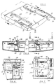
- Figure 1 is a perspective view showing a cargo ramp having various features of the invention, including cargo rails in conjunction with a cargo moving system;
- Figure 2 is a cross-sectional view along lines 2-2 of Figure 1, showing details of the cargo moving system;
- Figure 3 is a cross-sectional view along lines 3-3 of Figure 2, showing further details of the cargo moving system;
- Figure 4 is a cross-sectional view along lines 4-4 of Figure 2, again showing details of the cargo moving system;
- Figure 5 is a perspective diagrammatic view of a modified embodiment of the cargo ramp, showing an adjustable cargo rail configuration;
- Figure 6 is a cross-sectional view along lines 6-6 of Figure 5, showing details of the actuator for the adjustable cargo rails;
- Figure 7 is a cross-sectional view along lines 7-7 of Figure 6, showing further details of the adjustable cargo rails actuator; and
- Figure 8 is a cross-sectional view along lines 8-8 of Figure 6, again showing further details of the adjustable cargo rails actuator.
- Referring now to Figure 1, there is shown a cargo ramp 10 for a cargo aircraft which embodies the cargo handling system of the invention. Cargo ramp 10 is comprised of a
forward ramp section 12 and an aft ramp section 14. The two ramp sections are connected by means of ahinge 16. Hinge 16 permits relative motion betweenramp sections 12 and 14 in pitch and may also permit relative motion in roll in certain embodiments.Forward ramp section 12 is connected at its forward end to the aircraftcargo bed floor 18 by means of ahinge 20, which permits relative motion between theforward ramp section 12 and thecargo bed floor 18 in pitch. Twoactuators 22 are attached to eachramp section 12, 14 at one end, and at the other end to some fixed point on the aircraft or on the ground, preferably the aircraft fuselage. The aircraft loadmaster may configure the ramp as desired by operation of the actuators to move each ramp section to its appropriate position. The resultant ramp offers the convenience of straight-across loading and unloading of cargo onto vehicles which have cargo bed heights different than the cargo bed height of the aircraft. Additional details of the hinged cargo ramp are disclosed in the related application entitled "HINGED CARGO RAMP," EP-A-0 569 538 filed on even date herewith, and herein incorporated by reference. - Again referring to Figure 1, a conventional fixed cargo rail system extends along the entire lengths of
ramp sections 12 and 14 and also along the length ofcargo bed floor 18. The cargo rail system consists of aleft rail 24 and aright rail 26 which are spaced a distance apart which is sufficient to fit a standardmilitary pallet 28 between them, with only a very slight spacing between the rails and each side of the pallet. Of course, the rails could be spaced to accommodate any other type of cargo, such as commercial pallets, depending on the type of cargo carried by the aircraft.Rails pallet 28 fits under the horizontal arm of the "L" on its respective rail so that thepallet 28 is held to the floor. The vertical arm of the "L" guides the motion of the pallet along the lengths of the ramp and cargo bed floor and serves to keep the pallet centered. The aft ends 30 of eachrail pallets 28 onto the ramp 10 and between therails cargo bed floor 18 and bothramp sections 12, 14 have a plurality of rollers (not shown) on their surfaces between therails pallets 28.Pallet retainers 32 are mounted on aft ramp section 14 and havefingers 34 which interengage withnotches 36 in thepallet 28 to assist in loading the pallet onto the ramp section 14, in the manner described in greater detail in the related application entitled "AIRCRAFT CARGO HANDLING SYSTEM," EP-A-0 569 546 filed on even date herewith and herein incorporated by reference. The system for moving cargo along the cargo bed floor between therails dogs 38 which move withinrespective slots 40. Eachrail rail 26 in order to avoid cluttering the drawing. - Figures 2 to 4 show the cargo moving system in greater detail. Viewing Figures 2 and 4 together, it can be seen that each
dog 38 in theaircraft cargo floor 18 is contained within ashuttle 42 which traverses achannel 44. Eachshuttle 42 is linked by means ofpins 46 to achain 48 so as to be driven lengthwise along thecargo floor 18, along with the chain, bymotors Motor 50 operates in reverse direction with respect tomotor 52 and the two motors operate alternately, so that the effect is to drive thechain 48 for a certain distance in one direction (aft, for example) and then to drive it an equivalent distance in the opposite direction (forwardly, in our example). Each motor is actuated by contact of astop pin 54, which travels along with thechain 48, and itsrespective stop switch chain 48 through a chainidler sprocket slot 40 by means of any other conventionally known means, such as a jackscrew which is driven by a geared motor. - The retraction mechanism for the
dog 38 is shown in Figures 2 and 3.Actuator 64 is mounted withinshuttle 42 andactuator shaft 66 is attached to dog 38 at its base. As seen most clearly in Figure 3, the dog is also mounted on apivot shaft 68. To retract thedog 38 below the surface of thecargo bed floor 18, theactuator shaft 66 is extended, thus pivoting the dog clockwise aboutpivot shaft 68 and thereby dropping the protrudingportion 70 ofdog 38 intoslot 40. To extend the protrudingportion 70 above the surface of the cargo bed floor in order to engage a pallet, theactuator shaft 66 is retracted, thereby rotating thedog 38 counter-clockwise about thepivot shaft 68. Theactuator 64 is pneumatically driven by a source of air from a manifold 72 which is supplied to the actuator through aflexible pressure line 74. The air could be obtained from a variety of sources, such as bleed air from the engine compressor, or a dedicated system compressor. Of course, other conventional actuation systems could be employed, such as hydraulic systems, systems driven by pressurized fluid generated by an on-board inert gas generator, or a servo motor which drives thedog 38 through a gear train, without changing the scope of the invention. - The above-described cargo moving system operates to move cargo along the
cargo bed floor 18. However, this system may also be employed to move cargo along theramp sections 12, 14. In Figure 1, adog 38 andslot 40 combination is shown onramp section 12. A single combination is shown for illustrative purposes, though, of course, a plurality of dogs and slots could be employed, depending on the length of the ramp and the desired range of motion of each dog. Additionally, though no cargo moving means is shown for the ramp section 14, one could certainly be employed, depending again on the desired system application and perceived needs. The drive system shown in Figures 2 to 4 applies specifically to the cargo moving system for the cargo bed floor, since it contemplates driving a plurality ofshuttles 42 on asingle chain 48 and it would not be desirable to extend that chain onto the ramp 10. However, a similar system could be employed for the ramp cargo movers, sized in accordance with the number of dogs in the ramp mover system. In operation, apallet 28 is loaded onto the cargo ramp 10 between therails pallet notches 36 is engaged with the first protrudingdog 38. This will occur on one of theramp sections 12, 14 if the ramp 10 is equipped with the cargo moving system, or otherwise it will occur near the aft end of thecargo bed floor 18. Of course, since eachrail notches 36 on both the left and right sides of the pallet will be engaged with one of thedogs 38. At this point,motor 50 will be actuated so that the chain is driven counter-clockwise about theidler sprockets slot 40 until it reaches the end of the slot. At the time thedog 38 reaches the end of theslot 40, thestop pin 54 contacts theswitch 56, shutting off the operating motor and initiating operation of theother motor 52. The switch contact also actuates a central controller (not shown) which causes all of thedog actuators 64 to extend, thus retracting each of thedogs 38. The chain is thus driven in a clockwise direction, during which time all of thedogs 38 are retracted so that they do not inadvertently engage thepallet notches 36 and pull the pallet back in an aft direction. When the dogs are all at the aft end of theirrespective slots 40 once again, the other stop pin 54 (not shown) contacts theother switch 58, shutting offmotor 52 and re-energizingmotor 50. This switch contact signals the central controller to retract all of thedog actuators 64, thus extending each of thedogs 38. The chain is now driven counter-clockwise again, the next protrudingdog 38 now engaging a notch in thepallet 28 and pulling the pallet along further in a forward direction. This process is repeated until the pallet has been transported a desired distance along thefloor 18, the pallet being passed bucket-brigade style from one dog to the next. Of course, a plurality of pallets can be transported simultaneously, in a continuous line along the length of the conveyor system. Should it be desired to move thecargo pallets 28 in an aft direction, for example, to unload them from the aircraft, the system may be operated in reverse. - Numerous modifications may be made to the above-described conveyor system, depending on the desired operating performance and the specified design parameters for the aircraft. For example, a single reversible motor may be employed to drive the chain instead of two motors each driving the chain in opposite directions. Another possibly desirable modification would be to control each dog individually with a separate chain drive and motor combination. This would allow the dogs to be controlled sequentially, with the first dog reaching the end of its slot as the second dog started traversing its slot, and so on. The result would be a continuous motion of the
pallet 28 along the conveyor, with thesecond dog 38 engaging the pallet as the first one disengaged. There would be no delay while all of thedogs 38 were returning from the end to the beginning of their respective slots during the return cycle. However, the control scheme for such a system would be more complex. The system would also be more costly, involving the use of a number of chain drives and motors, and would also exact a significant weight penalty. Such considerations would involve deciding between a number of tradeoffs and would depend upon the overall objectives of the entire cargo handling system. - Another significant feature of the invention is that the
dogs 38 may also serve as cargo locks in flight. Once thepallets 28 have been on-loaded and are in their final flight positions, thedog actuators 64 may be extended to protrude thedogs 38 above the cargo bed floor surface, thus ensuring engagement of the dogs with thepallet notches 36 during flight operations. With the chain drives 48 locked in place for flight, the dogs thus serve as cargo locks, maintaining the pallets precisely in position for safety and enabling the loadmaster to know a pallet location precisely. - Figures 5 to 8 show an alternative embodiment which employs movable cargo rails 124, 126 on the
aft ramp section 114. The cargo bed floor is configured exactly as in Figure 1. Therails slots 142. Their purpose is to facilitate loading and unloading of cargo to and from the ramp, like the flared ends 30 in the Figure 1 embodiment, but with greater versatility. Theramp section 114 is shown having a cargo moving system as described above, with adog 138 mounted to travel alongslot 140. The dog and slot are positioned to be just inboard of therails cargo ramp section 114, as in the Figure 1 embodiment. Viewing Figures 6 to 8, details of the actuation system for the movable rails are shown. Jackscrew blocks 144 are attached to therails slots 142. The jackscrew blocks are threadedly mounted on ajackscrew 146, such that when the jackscrew is rotated the blocks move inwardly or outwardly, depending upon the direction of rotation of the jackscrew. In the embodiment shown, there is onejackscrew 146 for each set of opposing jackscrew blocks, the jackscrew blocks 144 forrail 124 being oppositely threaded onto thejackscrew 146 with respect to the jackscrew blocks 144 forrail 126, in order to ensure that the respective opposing blocks will move in opposite directions despite being mounted on the same jackscrew. Viewing Figure 6, synchronizedmotors 150 are depicted, which correspond tomotors 50 in the Figure 1 embodiment, and which act to drive chainidler sprockets 162, which inturn drive chains 148 to movedogs 138. This system serves to ensure uniform output, thereby ensuring that thedogs 138 for bothrails pallet 128 advances along the rails in an even manner. Motors 152 (not shown) may be similarly synchronized. Such a system using synchronized motors could also be employed in the Figure 1 embodiment. In the alternative, one of themotors 150 could instead comprise a differential gearbox, driven by theother motor 150 throughcommon shaft 154. Both the motor and the gearbox would in turn drive their respective pallet mover conveyors, ensuring synchronous movement of the conveyor systems for eachrail jackscrews 146 comprises a series ofdifferential gearboxes 180, which are driven by a single motor (not shown) through ashaft 182. Thus, each jackscrew is driven at exactly the same rotational speed, ensuring an even movement of therails separate motors 150 and two additional separate motors 152 could be used to drive the cargo moving conveyor and specifically dogs 138, being controlled by some other well known means to produce a uniform output. Regarding the jackscrew drive means,jackscrews 146 could alternatively be driven individually by separate synchronized drive motors and gearboxes. Furthermore,separate jackscrews 146 could be employed with respect to eachrail blocks 144 on each rail so that the rail stayed in alignment. All of these equivalents would be within the scope of this invention for either embodiment and may occur to one of ordinary skill in the art. However, regardless of the drive mechanism employed, control of rail movement is obtained by controlling the motors and actuators either by manual switches or by an automated control sequence actuated by the loadmaster and dependent upon the cargo being loaded or unloaded. - In operation, to load a pallet onto the aircraft, the
rails shaft 182 is driven to rotate by the aforementioned motor (not shown), the shaft in turn driving eachjackscrew 146 through their respectivedifferential gearboxes 180 in a uniform manner. The threaded engagement between the jackscrew blocks 144 and thejackscrews 146 causes bothblocks 144 on each jackscrew 146 to move outboard alongslots 142, thereby creating a greater spacing betweenrails pallet 128 is easily loaded onto the ramp between therails slot 142, by rotatingshaft 182 in the opposite direction, thereby rotating thejackscrews 146 in the opposite direction. At this point, the pallet is aligned and centered on theramp section 114, with the left and right edges snugly fitted between therails - Although exemplary embodiments of the invention have been shown and described, many changes, modifications, and substitutions may occur to one of ordinary skill in the art without departing from the scope of the invention as defined in the appended claims.
- In particular, it may be noted that this invention could be used with any state of the art cargo ramp for any type of transport vehicle, and is not in any way limited to use with segmented, hinged cargo ramps, nor is it limited to aircraft applications.
Claims (7)
- A cargo handling system for loading, unloading, and securing cargo with notches (36) therein, said cargo handling system being characterized by:a cargo bed floor (10) having a length fore and aft and (10) a plurality of slots (40, 140) collinearly arranged along said length, each of said slots (40, 140) being evenly spaced from one another and oriented lengthwise with respect to said floor;dogs (38, 138) each being movable between a retracted position and an extended position in which the dog extends above the surface of said cargo bed floor (10) from said slots (40, 140), and the dogs being for engaging a notch (36) in said cargo when the dogs are in the extended position, each of said dogs (38, 138) being adapted to move from one end of said slot (40, 140) to the other end thereof to thereby move cargo along the cargo bed floor (10).
- The cargo handling system as recited in claim 1, further characterized in that said cargo bed floor has:a second plurality of slots (40, 140) collinearly arranged along the length of said floor, said second plurality of slots (40, 140) being spaced from said plurality of slots (40, 140) widthwise with respect to said cargo bed floor, said second plurality of slots (40, 140) being identical and parallel to said plurality of slots (40, 140); and further dogs (38, 138), each dog (38, 138) being movable between a retracted position and an extended position in which the dog extends above the surface of said cargo bed floor (10) from said second plurality of slots (40, 140), the dogs being for engaging a notch (36) in said cargo when the dogs are in the extended position,
wherein said dogs (38, 138) extending from said plurality of slots (40, 140) are for engaging notches (36) on one side of said cargo and said dogs (38, 138) extending from said second plurality of slots (40, 140) are for engaging notches (36) on the other side of said cargo, each of said dogs (38, 138) being adapted to move from one end of each of said slots (40, 140) to the other end thereof while being so engaged to thereby move said cargo along the length of said cargo bed floor, said cargo moving in sequence from slot (40, 140) to slot (40, 140). - The cargo handling system as recited in claim 1 or 2, including a cargo pallet (28), and further characterized in that said cargo bed floor further has:parallel fixed cargo rails (24, 26, 124, 126) extending along the length of said cargo bed floor (10) and spaced widthwise sufficiently to accommodate the cargo pallet (28) therebetween, said cargo pallet (28) fitting snugly between said rails (24, 26, 126, 124), wherein said plurality of slots (40, 140) are arranged inboard of said rails (24, 26, 126, 124) and each of said dogs (38, 138) are adapted to engage a notch (36) along the side of said cargo pallet (28) when said dog (38, 138) is in an extended position, said dogs (38, 138) being further adapted to move from one end of each of said slots (40, 140) to the other end thereof while being so engaged to thereby move said cargo pallet (28) along the length of said cargo bed floor (10) between said rails (24, 26, 126, 124).
- The cargo handling system as recited in any one of the preceding claims further characterized by:at least one cargo ramp section, said cargo ramp section being attached to the aft end of said cargo bed floor (10);parallel cargo rails (24, 26, 126, 124) extending along the length of said cargo ramp section, each of said cargo rails (24, 26, 126, 124) being mounted within at least one slot (142) arranged widthwise with respect to said cargo ramp section; andactuator means (22) for moving each of said cargo rails (24, 26, 126, 124) along its respective slot (142) to thereby vary the spacing between said cargo rails (24, 26, 126, 124).
- The cargo handling system as recited in claim 4, further characterized in that when said rails (24, 26, 126, 124) are both at the innermost end of their respective slots (142), each of said rails is aligned with said parallel fixed cargo rails (24, 26, 126, 124) on said cargo bed floor (10).
- The cargo handling system as recited in any one of the preceding claims, further characterized by actuators (64) mounted beneath each of said slots (40, 140) for retracting each of said dogs (38, 138) beneath said cargo bed floor (10) surface when cargo is not being moved or when returning said dog (38, 138) to the other end of said slot (40, 140) in order to continue moving cargo and for extending each of said dogs (38, 138) above said cargo bed floor (10) surface to engage one of said notches (36) for moving cargo.
- The cargo handling system as recited in claim 6, further characterized in that each of said actuators (64) is adapted to extend each of said dogs (38, 138) above said cargo bed floor (10) surface in a locked position
Applications Claiming Priority (3)
| Application Number | Priority Date | Filing Date | Title |
|---|---|---|---|
| US07/648,281 US5140716A (en) | 1991-01-31 | 1991-01-31 | Cargo rail system for an aircraft |
| PCT/US1992/000647 WO1992013760A1 (en) | 1991-01-31 | 1992-01-27 | Cargo rail system for an aircraft |
| US648281 | 2000-08-24 |
Publications (2)
| Publication Number | Publication Date |
|---|---|
| EP0569516A1 EP0569516A1 (en) | 1993-11-18 |
| EP0569516B1 true EP0569516B1 (en) | 1997-09-17 |
Family
ID=24600171
Family Applications (1)
| Application Number | Title | Priority Date | Filing Date |
|---|---|---|---|
| EP92905833A Expired - Lifetime EP0569516B1 (en) | 1991-01-31 | 1992-01-27 | Cargo rail system for an aircraft |
Country Status (6)
| Country | Link |
|---|---|
| US (1) | US5140716A (en) |
| EP (1) | EP0569516B1 (en) |
| JP (1) | JPH06507359A (en) |
| AT (1) | ATE158243T1 (en) |
| DE (1) | DE69222294T2 (en) |
| WO (1) | WO1992013760A1 (en) |
Families Citing this family (16)
| Publication number | Priority date | Publication date | Assignee | Title |
|---|---|---|---|---|
| US5609110A (en) * | 1993-10-12 | 1997-03-11 | Meacham; Patrick E. | 2D and 3D pilot-channel arrays |
| US5546870A (en) * | 1993-10-12 | 1996-08-20 | Meacham; Patrick E. | 2D and 3D pilot-channel arrays |
| US6854147B1 (en) * | 2002-04-05 | 2005-02-15 | George E. Ahlsten | Loading ramp apparatus |
| USD505238S1 (en) * | 2003-05-06 | 2005-05-17 | Ronald I. Robertson | Vehicle ramp |
| US7108228B1 (en) * | 2005-02-02 | 2006-09-19 | Manfred Marshall | Hydrogen-fueled spacecraft |
| US7444697B2 (en) * | 2006-05-12 | 2008-11-04 | Pamela Williams | Travel pillow |
| GB0609892D0 (en) * | 2006-05-18 | 2006-06-28 | Airbus Uk Ltd | Aircraft walkway |
| US7785056B2 (en) * | 2006-08-22 | 2010-08-31 | The Boeing Company | Cargo transport system and method |
| US20100223740A1 (en) * | 2009-01-09 | 2010-09-09 | Pratt Michael J | Motorcycle Ramp with Resting Platform |
| US8690103B2 (en) * | 2010-01-19 | 2014-04-08 | Goodrich Corporation | Method and apparatus for converting aircraft from commercial to military freight service |
| GB2486201A (en) * | 2010-12-06 | 2012-06-13 | Blackrock Engineering Ltd | Pneumatic roller arrangement |
| US9428284B2 (en) | 2013-05-31 | 2016-08-30 | The Boeing Company | Cargo container transfer system and method |
| FR3048227B1 (en) * | 2016-02-25 | 2019-06-28 | Airbus Operations | UNIT FLOOR AND FRONT AIRCRAFT TIP COMPRISING SUCH A FLOOR AND METHOD FOR INTEGRATING SUCH FRONT POINT |
| US20240002175A1 (en) * | 2022-07-01 | 2024-01-04 | Kevin D. McGushion | Methods, Systems and Devices for Efficient and Rapid Autonomous Delivery of Goods |
| EP4594184A1 (en) * | 2022-09-30 | 2025-08-06 | Textron Systems Corporation | Roller-and-rail cargo handling system with pallet-moving trolley |
| CN117184407B (en) * | 2023-09-08 | 2025-12-05 | 兰州万里航空机电有限责任公司 | An aircraft electric crane guide rail docking device and method |
Citations (2)
| Publication number | Priority date | Publication date | Assignee | Title |
|---|---|---|---|---|
| US3850283A (en) * | 1972-05-05 | 1974-11-26 | Aircraft Mechanics | Air cargo container loader |
| US4344726A (en) * | 1979-04-02 | 1982-08-17 | Brooks & Perkins, Incorporated | Cargo handling apparatus |
Family Cites Families (12)
| Publication number | Priority date | Publication date | Assignee | Title |
|---|---|---|---|---|
| US3203527A (en) * | 1962-10-26 | 1965-08-31 | Aircraft cargo handling system | |
| US3524412A (en) * | 1968-11-18 | 1970-08-18 | Banner Metals Inc | Inclined ramp which enables a wheeled base to traverse therealong in a horizontal position |
| US3606842A (en) * | 1969-05-05 | 1971-09-21 | Basil George Verbick | Adjustable retainer |
| US4072242A (en) * | 1975-04-30 | 1978-02-07 | Cook Franklin F | Unloading tailgate for self-unloading forage wagon |
| US4039163A (en) * | 1976-04-05 | 1977-08-02 | The Boeing Company | Aircraft cargo ramp |
| US4101081A (en) * | 1977-03-14 | 1978-07-18 | Ritter Brothers Enterprises, Inc. | Hay loading, transporting and feeding system |
| JPS54120181A (en) * | 1978-03-09 | 1979-09-18 | Shin Meiwa Ind Co Ltd | Pneumatic roller conveyor vehicle |
| US4235399A (en) * | 1979-04-09 | 1980-11-25 | The Boeing Company | Cargo ramp |
| GB2126189B (en) * | 1982-08-27 | 1985-11-06 | Package Control Ltd | Load transporting apparatus |
| FR2573372B1 (en) * | 1984-11-19 | 1987-02-06 | Malemant Bertrand | IMPROVEMENTS IN MOUNTING RETRACTABLE TRAILS IN TRANSPORT VEHICLES |
| DE3507676A1 (en) * | 1985-03-05 | 1986-09-11 | Maschinenfabrik Müller-Weingarten AG, 7987 Weingarten | DEVICE FOR MOVING GRIPPERS ON THE GRIPPER RAILS OF A STEP PRESS |
| US4850788A (en) * | 1987-07-13 | 1989-07-25 | Dickson Industries, Inc. | Ramp assembly for trailers and the like |
-
1991
- 1991-01-31 US US07/648,281 patent/US5140716A/en not_active Expired - Fee Related
-
1992
- 1992-01-27 JP JP4506260A patent/JPH06507359A/en active Pending
- 1992-01-27 EP EP92905833A patent/EP0569516B1/en not_active Expired - Lifetime
- 1992-01-27 AT AT92905833T patent/ATE158243T1/en not_active IP Right Cessation
- 1992-01-27 WO PCT/US1992/000647 patent/WO1992013760A1/en not_active Ceased
- 1992-01-27 DE DE69222294T patent/DE69222294T2/en not_active Expired - Fee Related
Patent Citations (2)
| Publication number | Priority date | Publication date | Assignee | Title |
|---|---|---|---|---|
| US3850283A (en) * | 1972-05-05 | 1974-11-26 | Aircraft Mechanics | Air cargo container loader |
| US4344726A (en) * | 1979-04-02 | 1982-08-17 | Brooks & Perkins, Incorporated | Cargo handling apparatus |
Non-Patent Citations (5)
| Title |
|---|
| CH-A- 668 758 * |
| DE-A- 2 735 737 * |
| EP-A- 0 196 582 * |
| US-A- 3 850 283 * |
| US-A- 4 344 726 * |
Also Published As
| Publication number | Publication date |
|---|---|
| EP0569516A1 (en) | 1993-11-18 |
| DE69222294D1 (en) | 1997-10-23 |
| US5140716A (en) | 1992-08-25 |
| ATE158243T1 (en) | 1997-10-15 |
| DE69222294T2 (en) | 1998-04-02 |
| JPH06507359A (en) | 1994-08-25 |
| WO1992013760A1 (en) | 1992-08-20 |
Similar Documents
| Publication | Publication Date | Title |
|---|---|---|
| US5140716A (en) | Cargo rail system for an aircraft | |
| EP0647575B1 (en) | Apparatus for transferring cargoes | |
| US3710961A (en) | Transfer device | |
| EP0569546B1 (en) | Aircraft cargo handling system | |
| US4544319A (en) | Cargo transfer system | |
| US3978975A (en) | Cargo power drive unit | |
| US8864079B2 (en) | Aircraft cargo compartment container crane system | |
| US3612316A (en) | Cargo loading and restraint system | |
| EP0287559B1 (en) | Device for moving goods in the cargo space of an aircraft | |
| CN108177931B (en) | Conveying equipment capable of realizing free bending rail conveying goods | |
| US6655893B2 (en) | Extensible conveyor and frame for vehicle load transfer | |
| WO2008122381A2 (en) | Conveying apparatus | |
| US6019314A (en) | Aircraft handling apparatus | |
| US3620353A (en) | Chain-drive cargo-handling system | |
| CN109368301A (en) | Push-pull device at fixed for material entrucking | |
| US3313429A (en) | Vehicle loading and unloading apparatus | |
| US5253381A (en) | Hinged cargo ramp | |
| US3337069A (en) | Cargo elevator automatic loader and unloader | |
| EP2427367B1 (en) | Payload handling apparatus and system | |
| EP1542892B1 (en) | Rail car door closer | |
| US4195962A (en) | Platform loading system | |
| US3999671A (en) | Article handling system | |
| DE2415760C2 (en) | Device for the automatic loading and unloading of an elevator car | |
| CN209009456U (en) | Push-pull device at fixed for material entrucking | |
| EP0664255B1 (en) | Aircraft restraining system |
Legal Events
| Date | Code | Title | Description |
|---|---|---|---|
| PUAI | Public reference made under article 153(3) epc to a published international application that has entered the european phase |
Free format text: ORIGINAL CODE: 0009012 |
|
| AK | Designated contracting states |
Kind code of ref document: A1 Designated state(s): AT BE CH DE DK ES FR GB GR IT LI LU MC NL SE |
|
| 17P | Request for examination filed |
Effective date: 19930825 |
|
| 17Q | First examination report despatched |
Effective date: 19941124 |
|
| GRAG | Despatch of communication of intention to grant |
Free format text: ORIGINAL CODE: EPIDOS AGRA |
|
| GRAH | Despatch of communication of intention to grant a patent |
Free format text: ORIGINAL CODE: EPIDOS IGRA |
|
| GRAH | Despatch of communication of intention to grant a patent |
Free format text: ORIGINAL CODE: EPIDOS IGRA |
|
| GRAA | (expected) grant |
Free format text: ORIGINAL CODE: 0009210 |
|
| AK | Designated contracting states |
Kind code of ref document: B1 Designated state(s): AT BE CH DE DK ES FR GB GR IT LI LU MC NL SE |
|
| PG25 | Lapsed in a contracting state [announced via postgrant information from national office to epo] |
Ref country code: NL Free format text: LAPSE BECAUSE OF FAILURE TO SUBMIT A TRANSLATION OF THE DESCRIPTION OR TO PAY THE FEE WITHIN THE PRESCRIBED TIME-LIMIT Effective date: 19970917 Ref country code: LI Effective date: 19970917 Ref country code: IT Free format text: LAPSE BECAUSE OF FAILURE TO SUBMIT A TRANSLATION OF THE DESCRIPTION OR TO PAY THE FEE WITHIN THE PRESCRIBED TIME-LIMIT;WARNING: LAPSES OF ITALIAN PATENTS WITH EFFECTIVE DATE BEFORE 2007 MAY HAVE OCCURRED AT ANY TIME BEFORE 2007. THE CORRECT EFFECTIVE DATE MAY BE DIFFERENT FROM THE ONE RECORDED. Effective date: 19970917 Ref country code: GR Free format text: LAPSE BECAUSE OF FAILURE TO SUBMIT A TRANSLATION OF THE DESCRIPTION OR TO PAY THE FEE WITHIN THE PRESCRIBED TIME-LIMIT Effective date: 19970917 Ref country code: ES Free format text: THE PATENT HAS BEEN ANNULLED BY A DECISION OF A NATIONAL AUTHORITY Effective date: 19970917 Ref country code: DK Free format text: LAPSE BECAUSE OF NON-PAYMENT OF DUE FEES Effective date: 19970917 Ref country code: CH Effective date: 19970917 Ref country code: BE Effective date: 19970917 Ref country code: AT Effective date: 19970917 |
|
| REF | Corresponds to: |
Ref document number: 158243 Country of ref document: AT Date of ref document: 19971015 Kind code of ref document: T |
|
| REG | Reference to a national code |
Ref country code: CH Ref legal event code: EP |
|
| REF | Corresponds to: |
Ref document number: 69222294 Country of ref document: DE Date of ref document: 19971023 |
|
| PG25 | Lapsed in a contracting state [announced via postgrant information from national office to epo] |
Ref country code: SE Effective date: 19971217 |
|
| ET | Fr: translation filed | ||
| NLV1 | Nl: lapsed or annulled due to failure to fulfill the requirements of art. 29p and 29m of the patents act | ||
| PGFP | Annual fee paid to national office [announced via postgrant information from national office to epo] |
Ref country code: LU Payment date: 19980302 Year of fee payment: 7 |
|
| PGFP | Annual fee paid to national office [announced via postgrant information from national office to epo] |
Ref country code: CH Payment date: 19980310 Year of fee payment: 7 |
|
| REG | Reference to a national code |
Ref country code: CH Ref legal event code: PL |
|
| PGFP | Annual fee paid to national office [announced via postgrant information from national office to epo] |
Ref country code: MC Payment date: 19980622 Year of fee payment: 7 |
|
| PLBE | No opposition filed within time limit |
Free format text: ORIGINAL CODE: 0009261 |
|
| STAA | Information on the status of an ep patent application or granted ep patent |
Free format text: STATUS: NO OPPOSITION FILED WITHIN TIME LIMIT |
|
| 26N | No opposition filed | ||
| PG25 | Lapsed in a contracting state [announced via postgrant information from national office to epo] |
Ref country code: LU Free format text: LAPSE BECAUSE OF NON-PAYMENT OF DUE FEES Effective date: 19990127 |
|
| PG25 | Lapsed in a contracting state [announced via postgrant information from national office to epo] |
Ref country code: MC Free format text: LAPSE BECAUSE OF NON-PAYMENT OF DUE FEES Effective date: 19990731 |
|
| REG | Reference to a national code |
Ref country code: GB Ref legal event code: IF02 |
|
| PGFP | Annual fee paid to national office [announced via postgrant information from national office to epo] |
Ref country code: FR Payment date: 20021231 Year of fee payment: 12 |
|
| PGFP | Annual fee paid to national office [announced via postgrant information from national office to epo] |
Ref country code: GB Payment date: 20030122 Year of fee payment: 12 |
|
| PGFP | Annual fee paid to national office [announced via postgrant information from national office to epo] |
Ref country code: DE Payment date: 20030131 Year of fee payment: 12 |
|
| PG25 | Lapsed in a contracting state [announced via postgrant information from national office to epo] |
Ref country code: GB Free format text: LAPSE BECAUSE OF NON-PAYMENT OF DUE FEES Effective date: 20040127 |
|
| PG25 | Lapsed in a contracting state [announced via postgrant information from national office to epo] |
Ref country code: DE Free format text: LAPSE BECAUSE OF NON-PAYMENT OF DUE FEES Effective date: 20040803 |
|
| GBPC | Gb: european patent ceased through non-payment of renewal fee |
Effective date: 20040127 |
|
| PG25 | Lapsed in a contracting state [announced via postgrant information from national office to epo] |
Ref country code: FR Free format text: LAPSE BECAUSE OF NON-PAYMENT OF DUE FEES Effective date: 20040930 |
|
| REG | Reference to a national code |
Ref country code: FR Ref legal event code: ST |