EP0569339A1 - Ramming device, more particularly for soil probing - Google Patents
Ramming device, more particularly for soil probing Download PDFInfo
- Publication number
- EP0569339A1 EP0569339A1 EP93810338A EP93810338A EP0569339A1 EP 0569339 A1 EP0569339 A1 EP 0569339A1 EP 93810338 A EP93810338 A EP 93810338A EP 93810338 A EP93810338 A EP 93810338A EP 0569339 A1 EP0569339 A1 EP 0569339A1
- Authority
- EP
- European Patent Office
- Prior art keywords
- slide
- profiles
- carriage
- rod
- weight
- Prior art date
- Legal status (The legal status is an assumption and is not a legal conclusion. Google has not performed a legal analysis and makes no representation as to the accuracy of the status listed.)
- Granted
Links
Images

Classifications
-
- E—FIXED CONSTRUCTIONS
- E02—HYDRAULIC ENGINEERING; FOUNDATIONS; SOIL SHIFTING
- E02D—FOUNDATIONS; EXCAVATIONS; EMBANKMENTS; UNDERGROUND OR UNDERWATER STRUCTURES
- E02D7/00—Methods or apparatus for placing sheet pile bulkheads, piles, mouldpipes, or other moulds
- E02D7/02—Placing by driving
- E02D7/06—Power-driven drivers
- E02D7/08—Drop drivers with free-falling hammer
Definitions
- the present invention relates to a pile driver, in particular for pile probes, according to the preamble of claim 1.
- Such ramming probes in contrast to drilling probes, can be carried out very easily and inexpensively, since ramming devices have a simple structure and are also easy to use.
- Piling equipment of the type mentioned above are known. They essentially have a frame which is equipped with guides in which the ram is guided and with a chain for lifting the ram. If the chain is endless and formed over deflection rollers, it has drivers which are designed as rod elements which are connected to the chain and protrude at right angles therefrom.
- the chain is located on the outside of the frame and parallel to the guides for the ram and outside the ram.
- the ram is provided with a bracket in which the bar element of the chain engages coming from below and pulls the ram up. This is due to the weight of the ram and the lever arm of the bar element a moment which acts on the chain and which must be absorbed by the chain by suitable devices.
- the chain is guided over a deflection roller.
- a similar pile driver is known, for example, from GB-PS 1 486 002, which is provided for driving piles.
- This pile driver has a frame in which the ram is guided. Outside the frame there is an encircling chain which is equipped with drivers which protrude above the chain and interact with the ram when it is being pulled up, so that a moment is also exerted on the chain, which also causes the above-mentioned disadvantage. An adjustment of the fall height of the ram is not provided for in this ramming device.
- the object of the invention is to design a ramming device, in particular for ramming probes, so that the ram to be pulled up is held securely by a driver, and that the ram is at a selectable and easily adjustable height by the driver is released and slides down the guides to strike the rod of the probe to be driven.
- the object is achieved by the features specified in the characterizing part of claim 1.
- the guides of the frame consist of two U-profiles, the legs of which are directed towards each other so that the carriage can be arranged between the U-profiles, and the guide rollers are supported on the inside of the legs .
- the parallel, endless means are also arranged between the U-profiles, the slide in front of and behind the latch mechanism, which is arranged in the central region of the slide, has openings through which the front run and the rear run, respectively of the two endless means.
- the carriage is advantageously equipped with a holding device which comes to lie outside the profiles and on which holding device a weight is releasably attached, which is easily exchangeable for another weight.
- the weight connected to the holding device of the slide is provided with an opening through which the rod to be rammed into the ground is guided with play.
- a detachably fastened, flange-shaped part is arranged on the rod, on which the weight strikes.
- the latch mechanism consists of a slide which has an integrally formed latch, which can be moved between the endless means and comes to rest in the area of action of the drivers.
- the slide is pressed into this position by spring force.
- the release is carried out by a pivot lever, one leg of which is coupled to the slide, and the other leg of which is equipped with a roller which runs onto a wedge which is attached to the guides in a height-adjustable manner. This ensures an inevitable and therefore safe release at the selected height.
- a further advantageous embodiment of the invention consists in that the position into which the slide is pressed by means of spring force and which corresponds to the driving position can be adjusted by an adjustable stop.
- the endless means can be equipped with several drivers, the area of which is which the pawl of the slide comes to lie to raise the slide, have a different distance from the slide.
- the stop which limits the front position of the slide, it can be caused that the carriage is pulled up by every driver, or by every second driver or, for example, only by every third driver that runs past the carriage. In this way, for example, the stroke frequency can be changed depending on the height of the slide.
- the wedge on which the swivel lever runs to pull back the slide and to release the slide is held in the longitudinal direction by means of a clamping device on the profiles.
- the clamping device on which the wedge is arranged is coupled to the slide in such a way that with each impact that the ram exerts on the rod to be driven in, the wedge is pulled by the amount by which the rod penetrates into the ground. This automatically ensures that the fall height remains the same regardless of the penetration of the bar into the ground. This is particularly important if the depth of penetration of the probe is recorded as a function of the energy provided, in order to draw conclusions about the nature of the soil.
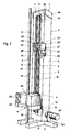
- the pile driver 1 according to FIG. 1 is composed of a frame 2, the guides 3 for the slide 4 of which are formed from two parallel profiles 5, 6 in the form of U-profiles.
- the profiles 5, 6 are connected to one another at their upper and lower ends by means of transverse webs 7 and 8, respectively, in such a way that the legs 9 and 10 of the two profiles 5, 6 are directed towards one another and that the profiles 5 and 6 are spaced apart from one another .
- the frame 2 is provided with a base 11, which serves as a base.
- a pair of guide rollers 12 and 13 is rotatably supported.
- a first endless roller chain 16 is guided over the first deflection rollers 14 and 15 of the two deflection roller pairs 12 and 13, which are designed as chain wheels.
- a second endless roller chain 19 is guided over the two second deflection rollers 17 and 18 of the two pairs of deflection rollers 12 and 13, which are also designed as sprockets.
- the first deflection rollers 14 and 15 are connected to the second deflection rollers 17 and 18 in a rotationally rigid manner at a distance from one another.
- the deflection roller pair 13 is driven by a motor 20 which is attached to the base 11. This motor 20 is designed as a hydraulic motor, the speed of which is variable.
- the carriage 4 which is guided in the profiles 5 and 6, as can be seen from FIGS. 2 to 4, is provided with a latch mechanism. As a result, the carriage 4 can be pulled up by the two roller chains 16 and 19, between which drivers 21 are fastened.
- the carriage 4 has a holding device 22, from which a weight 23 is received.
- the weight 23 is detachably connected to the holding device 22, so that it can easily be exchanged for another weight.
- the weight 23 has an opening 24 through which the rod 25 to be rammed into the ground is guided with play.
- the notch of the carriage in its upper position takes place via a wedge 26, which is held in the longitudinal direction by a clamping device 27 on the profiles 5 and 6.
- the clamping device 27 consists of a support plate 28, which is equipped with guide grooves, not shown, into which the legs 9 and 10 of the profiles 5 and 6 protrude, so that the clamping device 27 is guided.
- the clamping device 27 is clamped to the profiles 5 and 6 by means of clamping brackets 29 which are resiliently fastened to the support plate 28 and press against the surface of the legs 9 and 10 of the profiles 5 and 6. As a result, the clamping device is held in the corresponding position by friction.
- the support plate 28 has on the upper and lower edge each a right-angled tab 30 and 31, which are provided with holes through which a rod 32 is passed with play.
- the rod 32 is fixedly connected to the carriage 4 at its lower end.
- the upper pair of deflection rollers 12 can be mounted on a bracket 34, which is adjustable in the longitudinal direction with respect to the frame 2 by means of adjusting screws, not shown. As a result, the roller chains 18 and 19 can be retensioned.
- Fig. 2 the position of the carriage 4 is shown when it is in the lower position.
- the weight 23 rests on a flange-shaped part 35 which is attached to the rod 25, which is to be rammed into the ground, for receiving the stroke.
- the holding device 22 is detachably connected to the carriage 4 by means of screws 36.
- the carriage 4, which is box-shaped, is provided on both sides with four guide rollers 37, which are supported on the inside of the legs 9 and 10 of the profiles 5 and 6, so that the moments that occur when the carriage 4 is raised and when it strikes arise, be included.
- a bush 39 is fastened to cross members 40.
- the upper part of the sleeve 39 is with a Provide slot 41 through which a leg 42 of a pivot lever 43 projects.
- the pivot lever 43, the other leg 44 is equipped with a roller 45, is pivotally mounted on the box 38 by the bolt 46.
- the leg 42 engages with its end facing away from the bolt 46 into a recess 47 in the slide 48.
- the slide 48 is displaceable in the bush 39 by the pivot lever 43.
- the pawl 49 is integrally formed on the front end of the slide 48.
- the pivoting lever 46 is pulled into the position shown in FIG. 2 by the spring force exerted by the tension spring 50. This position is limited by the stop 51, which is held adjustably by a screw thread in the bush 39.
- the pawl 49 projects between the roller chains 16 and 19, which form the front run 52 in this area.
- the direction of rotation of the lower pair of guide rollers 12 causes the front run 52 of the roller chains 16 and 19 to move upward.
- the driver 21, which is fastened between the roller chains 16 and 19, abuts the pawl 49 with its upper contact surface, the carriage 4 is raised.
- roller chains 16 and 19 continue to run, the driver 21 bypasses the upper pair of guide rollers 13, passes through the rear run 53 and the lower pair of guide rollers 12 again under the pawl 49 of the slider 48, which are now again in the dash-dotted, front position lie, whereby the process is repeated.
- a plurality of drivers 21, for example four, can be attached along the roller chains 16 and 19, which are at a constant distance from one another. This means that four strokes and consequently four strokes are carried out while the speed of the motor 20 remains the same during one revolution of the roller chains 16 and 19. The waiting time for the carriage 4 when the stroke has been carried out is reduced considerably until the next driver 21 can pull the carriage 4 up again. This is particularly advantageous for small heads.
- the box 38 of the carriage can be seen.
- Four stub axles 54 are mounted on both sides of the box 38, on which the guide rollers 37 are rotatably mounted.
- the guide rollers 37 roll on the inside of the legs 9 and 10 of the profiles 5 and 6.
- the box 38 is provided in front of and behind the latch mechanism with an opening 58 and 59 through which the front run 52 and the rear run 53 of the roller chains 16 and 19 pass.
- roller chains 16 and 19 are guided in the area of the carriage 4, so that no evasive movement of the roller chains 16 and 19 can take place, in particular in the area of the pawl 49, which in particular could occur when the roller chains 16 and 19 are no longer optimally tensioned. This also ensures that the pawl 49 is securely latched to the driver 21 in this case.
- a driver 21 can for example consist of a full piece 55, while the other driver 21 consists of a U-shaped profile piece 56. Due to the fact that the front position of the pawl 49 of the slide 48 can be adjusted by the adjustable stop 51 (FIGS. 2 and 3), depending on the position of this stop, it can be achieved that only the drivers 21, which are equipped with a full piece 55, cause the carriage 4 to be pulled up while the driver 21 with the U-shaped profile piece 56 does not come into contact with the pawl 49.
- the stop 51 can, however, also be set such that both types of driver 21, both with the full piece 55 and with the U-shaped profile piece 56, cause the carriage to be lifted up.
- This piling device which allows a fall height of around two meters and whose drop weight is a maximum of 200 kg, can be easily operated by a single person, since the safety of the work processes is guaranteed.
- the base 11 of the pile driver 1 is advantageously equipped with bolts 57 (FIG. 1) in such a way that the pile driver 1 can be coupled to an existing three-point suspension of a tractor.
- this piling device can also be used if the rod 25 has to be rammed into the ground at an angle. It is also conceivable to equip the pile driver 1 with a hydraulic lifting device, by means of which rods 25 or probes rammed into the ground can be pulled out of the ground. It is also conceivable to provide the pile driver 1 with a crane device, by means of which weights 23 can be brought or exchanged on the holding device of the slide.
Landscapes
- Engineering & Computer Science (AREA)
- General Engineering & Computer Science (AREA)
- General Life Sciences & Earth Sciences (AREA)
- Mining & Mineral Resources (AREA)
- Paleontology (AREA)
- Civil Engineering (AREA)
- Life Sciences & Earth Sciences (AREA)
- Structural Engineering (AREA)
- Placing Or Removing Of Piles Or Sheet Piles, Or Accessories Thereof (AREA)
- Measuring Leads Or Probes (AREA)
- Dram (AREA)
- Measuring Or Testing Involving Enzymes Or Micro-Organisms (AREA)
- Investigation Of Foundation Soil And Reinforcement Of Foundation Soil By Compacting Or Drainage (AREA)
Abstract
Description
Die vorliegende Erfindung bezieht sich auf ein Rammgerät, insbesondere für Rammsondierungen, gemäss dem Oberbegriff des Patentanspruches 1.The present invention relates to a pile driver, in particular for pile probes, according to the preamble of
Bei der Rammsondierung werden spezielle Sonden, die an Stahlstäben oder -rohren befestigt sind, durch ein Rammgerät in die Erde gerammt. In Abhängigkeit der geleisteten Energie des Rammkörpers wird die Eindringtiefe der Sonde aufgezeichnet. Aufgrund dieser Aufzeichnungen sind Rückschlüsse auf die Beschaffenheit des Bodens möglich.During the ramming probing, special probes, which are attached to steel rods or pipes, are rammed into the ground using a piling device. The penetration depth of the probe is recorded depending on the energy of the ram body. Based on these records, conclusions can be drawn about the nature of the soil.
Speziell ausgebildete hohle Sonden bis zu einem Durchmesser von 100 mm, die ebenfalls mittels eines Rammgerätes in den Boden gerammt werden, erlauben es auch, Bodenproben zu entmehmen.Specially designed hollow probes up to a diameter of 100 mm, which are also rammed into the ground using a piling device, also allow soil samples to be taken.
Derartige Rammsondierungen sind, im Gegensatz zu Bohrsondierungen, sehr einfach und billig durchzuführen, da Rammgeräte einen einfachen Aufbau aufweisen und ebenfalls einfach in der Bedienung sind.Such ramming probes, in contrast to drilling probes, can be carried out very easily and inexpensively, since ramming devices have a simple structure and are also easy to use.
Rammgeräte der obengenannten Art sind bekannt. Sie weisen im wesentlichen ein Rahmengestell auf, das mit Führungen, in welchen die Ramme geführt ist, und mit einer Kette zum Hochziehen der Ramme ausgerüstet ist. Wenn die Kette endlos und über Umlenkrollen ausgebildet ist, weist diese Mitnehmer auf, welche als Stabelemente ausgeführt sind, die mit der Kette verbunden sind und rechtwinklig davon abstehen. Die Kette ist aussenliegend zum Rahmengestell und parallel zu den Führungen für die Ramme und ausserhalb der Ramme angeordnet. Die Ramme ist mit einem Bügel versehen, in welchen das Stabelement der Kette von unten kommend eingreift und die Ramme hochzieht. Hierbei entsteht infolge des Gewichts der Ramme und des Hebelarmes des Stabelementes ein Moment, das auf die Kette wirkt, und das durch geeignete Vorrichtungen von der Kette aufgenommen werden muss. Zum Ausklinken der Ramme wird die Kette über eine Umlenkrolle geführt. Durch das Umlenken der Kette wird das daran befestigte Stabelement aus dem Bügel der Ramme herausgezogen, wobei durch die Umlenkung der Kette das Stabelement eine zusätzliche Schwenkbewegung ausführt, wonach die Ramme entlang den Führungen abwärts fällt und mit der Schlagfläche auf die in den Boden zu rammende Stange fällt.Piling equipment of the type mentioned above are known. They essentially have a frame which is equipped with guides in which the ram is guided and with a chain for lifting the ram. If the chain is endless and formed over deflection rollers, it has drivers which are designed as rod elements which are connected to the chain and protrude at right angles therefrom. The chain is located on the outside of the frame and parallel to the guides for the ram and outside the ram. The ram is provided with a bracket in which the bar element of the chain engages coming from below and pulls the ram up. This is due to the weight of the ram and the lever arm of the bar element a moment which acts on the chain and which must be absorbed by the chain by suitable devices. To release the ram, the chain is guided over a deflection roller. By deflecting the chain, the rod element attached to it is pulled out of the bracket of the ram, the rod element executing an additional pivoting movement by the deflection of the chain, after which the ram falls down along the guides and strikes the rod to be rammed into the ground falls.
Diese Rammgeräte weisen den Nachteil auf, dass das Verstellen der Fallhöhe der Ramme nicht ohne weiteres möglich ist, sondern zusätzliche Aufwendungen in Form einer in der Höhe verstellbaren Umlenkrolle erfordert. Des weiteren ist durch das Moment, das durch das Stabelement auf die Kette wirkt, ein gewisses Sicherheitsrisiko im Hinblick auf das sichere Halten der Ramme durch das Stabelement während des Hochfahrens vorhanden.These piling rigs have the disadvantage that it is not readily possible to adjust the falling height of the ram, but rather requires additional expenditure in the form of a deflection roller which is adjustable in height. Furthermore, due to the moment acting on the chain through the bar element, there is a certain safety risk with regard to the ram being held securely by the bar element during the start-up.
Ein ähnliches Rammgerät ist beispielsweise aus der GB-PS 1 486 002 bekannt, welches zum Einrammen von Pfählen vorgesehen ist. Dieses Rammgerät weist ein Rahmengestell auf, in welchem die Ramme geführt ist. Ausserhalb des Rahmengestells ist eine umlaufende Kette angeordnet, die mit Mitnehmern ausgestattet ist, welche über die Kette vorstehen und mit der Ramme beim Hochziehen zusammenwirken, so dass ebenfalls ein Moment auf die Kette ausgeübt wird, wodurch ebenfalls der obengenannte Nachteil eintritt. Eine Verstellung der Fallhöhe der Ramme ist bei diesem Rammgerät nicht vorgesehen.A similar pile driver is known, for example, from GB-
Die Aufgabe der Erfindung besteht darin, ein Rammgerät, insbesondere für Rammsondierungen, so zu gestalten, dass die hochzuziehende Ramme von einem Mitnehmer sicher gehalten ist, und dass die Ramme auf einer wählbaren und einfach zu verstellenden Höhe vom Mitnehmer frei gegeben wird und entlang den Führungen abwärts gleitet, um den Schlag auf die Stange der einzurammenden Sonde auszuüben.The object of the invention is to design a ramming device, in particular for ramming probes, so that the ram to be pulled up is held securely by a driver, and that the ram is at a selectable and easily adjustable height by the driver is released and slides down the guides to strike the rod of the probe to be driven.
Erfindungsgemäss erfolgt die Lösung der Aufgabe durch die in der Kennzeichnung des Anspruches 1 angegebenen Merkmale.According to the invention, the object is achieved by the features specified in the characterizing part of
Durch das Nebeneinander-Anordnen zweier parallel geführter endloser Mittel und durch das Anbringen der Mitnehmer zum Anheben der Ramme zwischen den beiden endlosen Mitteln wird in vorteilhafter Weise erreicht, dass durch den Mitnehmer auf die endlosen Mittel kein Moment ausgeübt wird, wenn eine Ramme, gebildet durch den Schlitten und des daran angehängten Gewichtes, über einen Klinkmechanismus durch den Mitnehmer hochgezogen wird.By arranging two endless means guided parallel to one another and by attaching the drivers for lifting the ram between the two endless means, it is advantageously achieved that the driver does not exert any moment on the endless means when a ram is formed by the carriage and the weight attached to it is pulled up by the catch via a latch mechanism.
Eine weitere vorteilhafte Ausgestaltung der Erfindung besteht darin, dass die Führungen des Rahmengestells aus zwei U-Profilen bestehen, deren Schenkel gegeneinander gerichtet sind, so dass der Schlitten zwischen den U-Profilen angeordnet werden kann, und die Führungsrollen auf der Innenseite der Schenkel abgestützt sind. In vorteilhafter Weise sind die parallel geführten, endlosen Mittel ebenfalls zwischen den U-Profilen angeordnet, wobei der Schlitten vor und hinter dem Klinkmechanismus, welcher im mittleren Bereich des Schlittens angeordnet ist, Öffnungen aufweist, durch welche je das vordere Trum bzw. das hintere Trum der beiden endlosen Mittel geführt sind. Dies bedeutet, dass die beiden endlosen Mittel im Bereich des Klinkmechanismus durch den Schlitten geführt sind, wodurch die beiden endlosen Mittel gegenüber dem Klinkmechanismus des Schlittens keine ausweichende Bewegung ausführen können, so dass zwischen dem Klinkmechanismus und den zwischen den endlosen Mitteln angeordneten Mitnehmer im Hochziehvorgang des Schlittens eine sichere Verbindung gewährleistet ist.Another advantageous embodiment of the invention is that the guides of the frame consist of two U-profiles, the legs of which are directed towards each other so that the carriage can be arranged between the U-profiles, and the guide rollers are supported on the inside of the legs . Advantageously, the parallel, endless means are also arranged between the U-profiles, the slide in front of and behind the latch mechanism, which is arranged in the central region of the slide, has openings through which the front run and the rear run, respectively of the two endless means. This means that the two endless means in the region of the latch mechanism are guided through the slide, as a result of which the two endless means cannot perform an evasive movement relative to the latch mechanism of the slide, so that during the pull-up process between the latch mechanism and the drivers arranged between the endless means a secure connection is guaranteed.
In vorteilhafter Weise ist der Schlitten mit einer Halteeinrichtung ausgerüstet, die ausserhalb der Profile zu liegen kommt, und auf welcher Halteeinrichtung ein Gewicht lösbar befestigt ist, welches leicht gegen ein anderes Gewicht auswechselbar ist. Das mit der Halteeinrichtung des Schlittens verbundene Gewicht ist mit einer Öffnung versehen, durch welche die in den Boden zu rammende Stange mit Spiel geführt ist. An der Stange ist ein lösbar befestigter, flanschförmiger Teil angeordnet, auf welchen das Gewicht aufschlägt. Durch die Führung der Stange mittels des Gewichts ist gewährleistet, dass jeder Schlag präzise ausgeführt wird, und dass die Stange in bezug auf das Gewicht keine ausweichende Bewegung ausführen kann.The carriage is advantageously equipped with a holding device which comes to lie outside the profiles and on which holding device a weight is releasably attached, which is easily exchangeable for another weight. The weight connected to the holding device of the slide is provided with an opening through which the rod to be rammed into the ground is guided with play. A detachably fastened, flange-shaped part is arranged on the rod, on which the weight strikes. By guiding the bar by weight, it is ensured that each stroke is carried out precisely and that the bar cannot make an evasive movement in relation to the weight.
In vorteilhafter Weise besteht der Klinkmechanismus aus einem Schieber, der eine angeformte Klinke aufweist, welche zwischen die endlosen Mittel verschoben werden kann und in den Wirkungsbereich der Mitnehmer zu liegen kommt. Der Schieber wird durch Federkraft in diese Lage gedrückt. Das Ausklinken erfolgt durch einen Schwenkhebel, dessen einer Schenkel mit dem Schieber gekoppelt ist, und dessen anderer Schenkel mit einer Rolle ausgerüstet ist, die auf einen Keil aufläuft, der an den Führungen höhenverstellbar angebracht ist. Dadurch ist ein zwangsläufiges und demzufolge sicheres Ausklinken auf der gewählten Höhe gewährleistet.Advantageously, the latch mechanism consists of a slide which has an integrally formed latch, which can be moved between the endless means and comes to rest in the area of action of the drivers. The slide is pressed into this position by spring force. The release is carried out by a pivot lever, one leg of which is coupled to the slide, and the other leg of which is equipped with a roller which runs onto a wedge which is attached to the guides in a height-adjustable manner. This ensures an inevitable and therefore safe release at the selected height.
Eine weitere vorteilhafte Ausgestaltung der Erfindung besteht darin, dass die Lage, in welche der Schieber mittels Federkraft gedrückt wird, und die der Mitnahmestellung entspricht, durch einen verstellbaren Anschlag einstellbar ist. Die endlosen Mittel können mit mehreren Mitnehmern ausgerüstet sein, deren Fläche, auf die die Klinke des Schiebers zum Hochfahren des Schlittens zu liegen kommt, vom Schlitten einen unterschiedlichen Abstand aufweisen. Durch das geeignete Einstellen des Anschlags, welcher die Vorderlage des Schiebers begrenzt, kann bewirkt werden, dass der Schlitten durch jeden Mitnehmer, oder durch jeden zweiten oder beispielsweise auch nur durch jeden dritten Mitnehmer, welcher am Schlitten vorbeiläuft, hochgezogen wird. Dadurch kann beispielsweise die Schlagfrequenz, abhängig von der Fallhöhe des Schlittens, verändert werden.A further advantageous embodiment of the invention consists in that the position into which the slide is pressed by means of spring force and which corresponds to the driving position can be adjusted by an adjustable stop. The endless means can be equipped with several drivers, the area of which is which the pawl of the slide comes to lie to raise the slide, have a different distance from the slide. By suitably adjusting the stop, which limits the front position of the slide, it can be caused that the carriage is pulled up by every driver, or by every second driver or, for example, only by every third driver that runs past the carriage. In this way, for example, the stroke frequency can be changed depending on the height of the slide.
Der Keil, auf welchen der Schwenkhebel zum Zurückziehen des Schiebers und zum Ausklinken des Schlittens aufläuft, ist über eine Klemmeinrichtung an den Profilen in Längsrichtung verschiebbar gehalten. Dadurch ist die Höheneinstellung des Keils sehr einfach. Des weiteren ist die Klemmeinrichtung, auf der der Keil angeordnet ist, mit dem Schlitten derart gekoppelt, dass bei jedem Schlag, den die Ramme auf die einzurammende Stange ausübt, der Keil um dasjenige Mass mitgezogen wird, um welches die Stange in den Boden eindringt. Dadurch ist automatisch gewährleistet, dass die Fallhöhe, unabhängig vom Eindringen der Stange in den Boden, immer gleich bleibt. Dies ist insbesondere dann von Bedeutung, wenn die Eindringtiefe der Sonde in Abhängigkeit der geleisteten Energie aufgezeichnet wird, um daraus Rückschlüsse auf die Bodenbeschaffenheit zu ziehen.The wedge on which the swivel lever runs to pull back the slide and to release the slide is held in the longitudinal direction by means of a clamping device on the profiles. This makes the height adjustment of the wedge very easy. Furthermore, the clamping device on which the wedge is arranged is coupled to the slide in such a way that with each impact that the ram exerts on the rod to be driven in, the wedge is pulled by the amount by which the rod penetrates into the ground. This automatically ensures that the fall height remains the same regardless of the penetration of the bar into the ground. This is particularly important if the depth of penetration of the probe is recorded as a function of the energy provided, in order to draw conclusions about the nature of the soil.
Weitere vorteilhafte Ausgestaltungen der Erfindung ergeben sich aus den weiteren abhängigen Ansprüchen.Further advantageous embodiments of the invention result from the further dependent claims.
Eine Ausführung der Erfindung wird nachfolgend anhand der Zeichnung beispielhaft näher beschrieben.An embodiment of the invention is described in more detail below by way of example with reference to the drawing.
Es zeigen
- Fig. 1 eine räumliche Darstellung eines Rammgerätes;
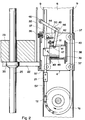
- Fig. 2 eine Schnittdarstellung durch den Schlitten mit dem Klinkmechanismus, wobei sich der Schlitten in der unteren Lage befindet.
- Fig. 3 eine Schnittdarstellung durch den Schlitten mit dem Klinkmechanismus, wobei sich der Schlitten in der hochgezogenen Ausklinklage befindet;
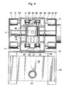
- Fig. 4 eine Schnittdarstellung quer durch den Schlitten und durch die Profile des Rahmengestells.
- Figure 1 is a spatial representation of a pile driver.
- Fig. 2 is a sectional view through the carriage with the latch mechanism, the carriage being in the lower position.
- Figure 3 is a sectional view through the carriage with the latch mechanism, the carriage being in the raised release position.
- Fig. 4 is a sectional view across the carriage and through the profiles of the frame.
Das Rammgerät 1 gemäss Fig. 1 setzt sich aus einem Rahmengestell 2 zusammen, dessen Führungen 3 für den Schlitten 4 aus zwei parallel angeordneten Profilen 5, 6 in Form von U-Profilen gebildet werden. Die Profile 5, 6 sind an ihrem oberen und ihrem unteren Ende mit Querstegen 7 bzw. 8 miteinander verbunden, dergestalt, dass die Schenkel 9 und 10 der beiden Profile 5, 6 gegeneinandergerichtet sind, und dass die Profile 5 und 6 einen gegenseitigen Abstand aufweisen. Das Rahmengestell 2 ist mit einem Sockel 11 versehen, welcher als Standfläche dient.The
Im oberen Bereich und im unteren Bereich des Rahmengestells 2 ist je ein Umlenkrollenpaar 12 bzw. 13 drehbar gelagert. Über die ersten Umlenkrollen 14 und 15 der beiden Umlenkrollenpaare 12 bzw. 13, die als Kettenräder ausgebildet sind, ist eine erste endlose Rollenkette 16 geführt. Über die beiden zweiten Umlenkrollen 17 und 18 der beiden Umlenkrollenpaare 12 bzw. 13, die ebenfalls als Kettenräder ausgebildet sind, ist eine zweite endlose Rollenkette 19 geführt. Die ersten Umlenkrollen 14 bzw. 15 sind mit den zweiten Umlenkrollen 17 bzw. 18 mit einem Abstand voneinander drehstarr verbunden. Das Umlenkrollenpaar 13 wird durch einen Motor 20, welcher am Sockel 11 befestigt ist, angetrieben. Dieser Motor 20 ist als Hydraulikmotor ausgebildet, dessen Drehzahl variabel ist.In the upper area and in the lower area of the
Der Schlitten 4, der in den Profilen 5 und 6 geführt ist, wie aus Fig. 2 bis 4 ersichtlich ist, ist mit einem Klinkmechanismus versehen. Dadurch kann der Schlitten 4 durch die beiden Rollenketten 16 und 19, zwischen welchen Mitnehmer 21 befestigt sind, hochgezogen werden. Der Schlitten 4 weist eine Halteeinrichtung 22 auf, von welcher ein Gewicht 23 aufgenommen wird. Das Gewicht 23 ist mit der Halteeinrichtung 22 lösbar verbunden, so dass es leicht gegen ein anderes Gewicht ausgetauscht werden kann. Das Gewicht 23 weist eine Öffnung 24 auf, durch welche die in den Boden zu rammende Stange 25 mit Spiel geführt ist.The
Das Ausklinken des Schlittens in seiner oberen Lage, das später noch in bezug auf Fig. 2 und 3 näher beschrieben wird, erfolgt über einen Keil 26, der durch eine Klemmeinrichtung 27 an den Profilen 5 und 6 in Längsrichtung verschiebbar gehalten ist. Die Klemmeinrichtung 27 besteht aus einer Tragplatte 28, die mit nicht dargestellten Führungsnuten ausgerüstet ist, in welche die Schenkel 9 und 10 der Profile 5 und 6 hineinragen, so dass die Klemmeinrichtung 27 geführt ist. Das Festklemmen der Klemmeinrichtung 27 an den Profilen 5 und 6 erfolgt über Klemmbügel 29, die federnd auf der Tragplatte 28 befestigt sind und gegen die Oberfläche der Schenkel 9 und 10 der Profile 5 und 6 drücken. Dadurch wird die Klemmeinrichtung in der entsprechenden Lage durch Reibung gehalten. Die Tragplatte 28 weist an der oberen und unteren Kante je eine rechtwinklig abgebogene Lasche 30 bzw. 31 auf, die mit Bohrungen versehen sind, durch welche eine Stange 32 mit Spiel hindurchgeführt ist. Die Stange 32 ist an ihrem unteren Ende mit dem Schlitten 4 fest verbunden. Auf der Stange 32 ist an dem dem Schlitten 4 abgewandten Endbereich und ausserhalb der Laschen 30 und 31 ein höhenverstellbarer Anschlag 33 angebracht.The notch of the carriage in its upper position, which will be described later with reference to FIGS. 2 and 3, takes place via a
Beim Hochfahren des Schlittens 4 gleitet die Stange 32 durch die beiden Laschen 30 und 31 hindurch, ebenfalls beim Herunterfallen des Schlittens 4. Der Anschlag 33 bewirkt aber, dass beim Eindringen der Stange 25 in den Boden, was bei jedem Schlag um ein bestimmtes Mass passiert, die Klemmeinrichtung 27 zusammen mit dem Keil 26 um dieses Eindringmass der Stange 25 nach unten verschoben wird. Dies bedeutet, dass die einmal eingestellte Fallhöhe, die durch die Einstellung des Anschlages 33 auf der Stange 32 festgelegt wird, während des Einrammens der Stange 25 in den Boden automatisch immer gleich bleibt.When the
Das obere Umlenkrollenpaar 12 kann auf einem Bügel 34 gelagert sein, welcher mittels nicht dargestellter Stellschrauben in Längsrichtung bezüglich des Rahmengestells 2 verstellbar ist. Dadurch können die Rollenketten 18 und 19 nachgespannt werden.The upper pair of
In Fig. 2 ist die Lage des Schlittens 4 dargestellt, wenn er sich in der unteren Lage befindet. Nach Ausführung des Schlages liegt das Gewicht 23 auf einem flanschförmigen Teil 35 auf, der an der Stange 25, die in den Boden zu rammen ist, zur Aufnahme des Schlages angebracht ist. Die Halteeinrichtung 22 ist mit dem Schlitten 4 über Schrauben 36 lösbar verbunden. Der Schlitten 4, welcher kastenförmig aufgebaut ist, ist beidseitig mit je vier Führungsrollen 37 versehen, welche sich auf den Innenseiten der Schenkel 9 und 10 der Profile 5 und 6 abstützen, so dass die entstehenden Momente, die beim Hochfahren des Schlittens 4 und beim Schlag entstehen, aufgenommen werden.In Fig. 2 the position of the
Im mittleren Bereich des den Schlitten 4 bildenden Kastens 38 ist eine Büchse 39 an Querträgern 40 befestigt. Der obere Teil der Büchse 39 ist mit einem Schlitz 41 versehen, durch welchen ein Schenkel 42 eines Schwenkhebels 43 hindurchragt. Der Schwenkhebel 43, dessen anderer Schenkel 44 mit einer Rolle 45 ausgerüstet ist, ist am Kasten 38 durch den Bolzen 46 schwenkbar gelagert. Der Schenkel 42 greift mit seinem dem Bolzen 46 abgewandten Ende in eine Ausnehmung 47 des Schiebers 48. Der Schieber 48 ist in der Büchse 39 durch den Schwenkhebel 43 verschiebbar. Am vorderen Ende des Schiebers 48 ist die Klinke 49 angeformt. Durch die Federkraft, ausgeübt durch die Zugfeder 50, wird der Schwenkhebel 46 in die in Fig. 2 dargestellte Lage gezogen. Diese Lage wird durch den Anschlag 51, der durch ein Schraubgewinde in der Büchse 39 verstellbar gehalten ist, begrenzt.In the central region of the
Die Klinke 49 ragt zwischen die Rollenketten 16 und 19, die in diesem Bereich das Vordertrum 52 bilden. Durch die Drehrichtung des unteren Umlenkrollenpaares 12 erfährt das Vordertrum 52 der Rollenketten 16 und 19 eine Aufwärtsbewegung. Der Mitnehmer 21, der zwischen den Rollenketten 16 und 19 befestigt ist, stösst mit seiner oberen Auflagefläche an die Klinke 49 an, der Schlitten 4 wird angehoben.The
In der hochgezogenen Lage des Schlittens 4, wie es in Fig. 3 dargestellt ist, läuft die Rolle 45 des Schwenkhebels 43 auf den Keil 26 auf, der an den Profilen 5, 6 gehalten ist. Dadurch erfährt der Schwenkhebel 43 eine Schwenkbewegung. Der Schenkel 42 zieht den Schieber 48 entgegen der Federkraft, ausgeübt durch die Zugfeder 50, in die in Fig. 3 dargestellte zurückgezogene Lage. Die Klinke 49, die während des Hochziehens des Schlittens 4 auf dem Mitnehmer 21 auflag, wie strichpunktiert dargestellt ist, wird dadurch vom Mitnehmer 21 zurückgezogen, der Schlitten 4 wird freigegeben und kann entlang der Schenkel 9 bzw. 10 der Profile 5 und 6, geführt durch die Führungsrollen 37 runterfallen, bis das Gewicht 23 auf dem in Fig. 3 nicht sichtbaren flanschförmigen Teil 35 der einzurammenden Stange 25 aufschlägt. Die Rollenketten 16 und 19 laufen weiter, der Mitnehmer 21 umfährt das obere Umlenkrollenpaar 13, gelangt über das hintere Trum 53 und das untere Umlenkrollenpaar 12 wieder unter die Klinke 49 des Schiebers 48, die sich nun wieder in der strichpunktierten, vorderen Lage befinden, zu liegen, wodurch der Vorgang wiederholt wird.In the raised position of the
Entlang der Rollenketten 16 und 19 können mehrere Mitnehmer 21 angebracht werden, beispielsweise vier, welche einen konstanten Abstand voneinander aufweisen. Dies bedeutet, dass bei gleichbleibender Drehzahl des Motors 20 während eines Umlaufs der Rollenketten 16 und 19 vier Hübe und demzufolge vier Schläge durchgeführt werden. Die Wartezeit für den Schlitten 4, wenn der Schlag ausgeführt wurde, wird wesentlich verkleinert, bis der nächste Mitnehmer 21 den Schlitten 4 wieder hochziehen kann. Dies ist insbesondere bei kleinen Fallhöhen von Vorteil.A plurality of
Aus Fig. 4, in welcher ein Querschnitt durch den Schlitten 4 dargestellt ist, ist der Kasten 38 des Schlittens ersichtlich. Beidseits des Kastens 38 sind vier Achsstümpfe 54 angebracht, auf welchen die Führungsrollen 37 drehbar gelagert sind. Die Führungsrollen 37 rollen auf der Innenseite der Schenkel 9 und 10 der Profile 5 und 6 ab. Der Kasten 38 ist vor und hinter dem Klinkmechanismus mit je einer Öffnung 58 und 59 versehen, durch welche das vordere Trum 52 bzw. das hintere Trum 53 der Rollenketten 16 und 19 hindurchlaufen. Durch diese Öffnungen 58 und 59 sind die Rollenketten 16 und 19 im Bereich des Schlittens 4 geführt, so dass keine Ausweichbewegung der Rollenketten 16 und 19 insbesondere im Bereich der Klinke 49 erfolgen kann, was insbesondere dann auftreten könnte, wenn die Rollenketten 16 und 19 nicht mehr optimal gespannt sind. Dadurch ist auch in diesem Fall ein sicheres Einklinken der Klinke 49 mit dem Mitnehmer 21 gewährleistet.4, in which a cross section through the
Wenn mehrere Mitnehmer 21 an den Rollenketten 16 und 19 angeordnet sind, können die Mitnehmer 21 unterschiedliche Formen aufweisen. Ein Mitnehmer 21 kann beispielsweise aus einem vollen Stück 55 bestehen, während der andere Mitnehmer 21 aus einem U-förmigen Profilstück 56 besteht. Dadurch, dass die vordere Lage der Klinke 49 des Schiebers 48 durch den verstellbaren Anschlag 51 (Figur 2 und 3) einstellbar ist, kann je nach Stellung dieses Anschlages erreicht werden, dass nur die Mitnehmer 21, die mit einem vollen Stück 55 ausgerüstet sind, ein Hochziehen des Schlittens 4 bewirken, während der Mitnehmer 21 mit dem U-förmigen Profilstück 56 nicht mit der Klinke 49 in Kontakt kommt. Der Anschlag 51 kann aber auch so eingestellt werden, dass beide Mitnehmerarten 21, sowohl mit dem vollen Stück 55 als auch mit dem U-förmigen Profilstück 56 ein Hochheben des Schlittens bewirken.If a plurality of
Dieses Rammgerät, das eine Fallhöhe von gegen zwei Meter zulässt und dessen Fallgewicht maximal 200 kg beträgt, lässt sich problemlos durch eine einzige Person bedienen, da die Sicherheit der Arbeitsvorgänge gewährleistet ist. In vorteilhafter Weise ist der Sockel 11 des Rammgerätes 1 derart mit Bolzen 57 (Figur 1) ausgerüstet, dass das Rammgerät 1 an eine bestehende Dreipunktaufhängung eines Traktors ankoppelbar ist.This piling device, which allows a fall height of around two meters and whose drop weight is a maximum of 200 kg, can be easily operated by a single person, since the safety of the work processes is guaranteed. The
Infolge der Kettenführung, der Klinkeinrichtung und der Führung des Schlittens 4 kann dieses Rammgerät auch verwendet werden, wenn die Stange 25 schräg in den Boden eingerammt werden muss. Es ist auch denkbar, das Rammgerät 1 mit einer hydraulischen Hebeeinrichtung auszurüsten, mittels welcher in den Boden eingerammte Stangen 25 bzw. Sonden aus dem Boden herausgezogen werden können. Es ist weiter denkbar, das Rammgerät 1 mit einer Kraneinrichtung zu versehen, mittels welcher Gewichte 23 auf die Halteeinrichtung des Schlittens gebracht bzw. ausgetauscht werden können.As a result of the chain guide, the latching device and the guidance of the
Claims (10)
Applications Claiming Priority (2)
| Application Number | Priority Date | Filing Date | Title |
|---|---|---|---|
| CH1470/92 | 1992-05-07 | ||
| CH147092 | 1992-05-07 |
Publications (2)
| Publication Number | Publication Date |
|---|---|
| EP0569339A1 true EP0569339A1 (en) | 1993-11-10 |
| EP0569339B1 EP0569339B1 (en) | 1996-10-23 |
Family
ID=4211239
Family Applications (1)
| Application Number | Title | Priority Date | Filing Date |
|---|---|---|---|
| EP93810338A Expired - Lifetime EP0569339B1 (en) | 1992-05-07 | 1993-05-07 | Ramming device, more particularly for soil probing |
Country Status (3)
| Country | Link |
|---|---|
| EP (1) | EP0569339B1 (en) |
| AT (1) | ATE144569T1 (en) |
| DE (1) | DE59304244D1 (en) |
Cited By (4)
| Publication number | Priority date | Publication date | Assignee | Title |
|---|---|---|---|---|
| WO2005073467A2 (en) * | 2004-01-29 | 2005-08-11 | Clark Equipment Company | Drop hammer |
| CN103061666A (en) * | 2013-01-12 | 2013-04-24 | 刘玉秋 | No-torque hole forming equipment |
| CN111851488A (en) * | 2019-04-28 | 2020-10-30 | 北京瑞力通地基基础工程有限责任公司 | Pile driver |
| CN114775593A (en) * | 2022-05-17 | 2022-07-22 | 中化地质矿山总局云南地质勘查院 | Anchoring device for preventing landslide geological disasters |
Families Citing this family (2)
| Publication number | Priority date | Publication date | Assignee | Title |
|---|---|---|---|---|
| NZ505698A (en) * | 2000-09-12 | 2002-12-20 | Rocktec Ltd | Rotating chain driven concrete impactor or breaker with variable height adjustment |
| EP1563145B1 (en) * | 2002-10-21 | 2012-04-04 | Terminator IP II S.A. | An improved device |
Citations (3)
| Publication number | Priority date | Publication date | Assignee | Title |
|---|---|---|---|---|
| US3207236A (en) * | 1963-04-15 | 1965-09-21 | Clyde E Shriner | Post driver |
| AU2761567A (en) * | 1968-08-19 | 1970-02-26 | Alfred Brenton Leslie | Improved post driver |
| FR2271344A1 (en) * | 1974-05-16 | 1975-12-12 | Bouyer Jean | Rig and hammer for driving posts - has endless belt driving vert. chain raising hammer to top of rail |
-
1993
- 1993-05-07 DE DE59304244T patent/DE59304244D1/en not_active Expired - Fee Related
- 1993-05-07 AT AT93810338T patent/ATE144569T1/en not_active IP Right Cessation
- 1993-05-07 EP EP93810338A patent/EP0569339B1/en not_active Expired - Lifetime
Patent Citations (3)
| Publication number | Priority date | Publication date | Assignee | Title |
|---|---|---|---|---|
| US3207236A (en) * | 1963-04-15 | 1965-09-21 | Clyde E Shriner | Post driver |
| AU2761567A (en) * | 1968-08-19 | 1970-02-26 | Alfred Brenton Leslie | Improved post driver |
| FR2271344A1 (en) * | 1974-05-16 | 1975-12-12 | Bouyer Jean | Rig and hammer for driving posts - has endless belt driving vert. chain raising hammer to top of rail |
Cited By (8)
| Publication number | Priority date | Publication date | Assignee | Title |
|---|---|---|---|---|
| WO2005073467A2 (en) * | 2004-01-29 | 2005-08-11 | Clark Equipment Company | Drop hammer |
| WO2005073467A3 (en) * | 2004-01-29 | 2005-10-20 | Clark Equipment Co | Drop hammer |
| US7237706B2 (en) | 2004-01-29 | 2007-07-03 | Clark Equipment Company | Drop hammer |
| CN100513691C (en) * | 2004-01-29 | 2009-07-15 | 克拉克设备公司 | Drop hammer |
| CN103061666A (en) * | 2013-01-12 | 2013-04-24 | 刘玉秋 | No-torque hole forming equipment |
| CN111851488A (en) * | 2019-04-28 | 2020-10-30 | 北京瑞力通地基基础工程有限责任公司 | Pile driver |
| CN114775593A (en) * | 2022-05-17 | 2022-07-22 | 中化地质矿山总局云南地质勘查院 | Anchoring device for preventing landslide geological disasters |
| CN114775593B (en) * | 2022-05-17 | 2023-11-24 | 中化地质矿山总局云南地质勘查院 | Anchoring device for preventing landslide geological disasters |
Also Published As
| Publication number | Publication date |
|---|---|
| DE59304244D1 (en) | 1996-11-28 |
| ATE144569T1 (en) | 1996-11-15 |
| EP0569339B1 (en) | 1996-10-23 |
Similar Documents
| Publication | Publication Date | Title |
|---|---|---|
| DE2642766C2 (en) | Device for pulling shoring walls, panels, sheet piles or similar shoring elements for trench shoring | |
| DE7529603U (en) | MATERIAL HANDLING DEVICE ATTACHED TO A TRACTOR | |
| DE102008046476B4 (en) | Laying device for laying curbs | |
| EP0569339B1 (en) | Ramming device, more particularly for soil probing | |
| DE2047215A1 (en) | Punching - or the like. - Street | |
| DE3122116C2 (en) | "Trailer coupling, especially for tractors" | |
| DE2946750C2 (en) | Device for raising and lowering ceiling formwork | |
| EP0775663A1 (en) | Device for manipulating submersible apparatus | |
| DE2929782C2 (en) | Device for cutting out and transporting a block of fermentation fodder | |
| DE3111343C2 (en) | "Device for splitting wood" | |
| DE3619214A1 (en) | Apparatus for driving in stakes or the like | |
| DE4218982A1 (en) | Device for drilling holes in vertical surfaces, e.g side panels in truck - has rectangular frame with rollers supported on panel's upper edge and drill in sliding mount on horizontal cross-piece. | |
| EP0900884B1 (en) | Hammering device especially for percussion probe driving | |
| DE102021104167B4 (en) | Cabin protection for a working machine cabin | |
| DE2645177C2 (en) | Wire cutting machine for cutting predetermined, adjustable lengths from a wire continuously fed to a cutting device | |
| DE1759042B2 (en) | Earth auger | |
| DE2323771C3 (en) | Device for attaching spacers to reinforcement in reinforced concrete construction | |
| DE286573C (en) | ||
| DE202018104017U1 (en) | rammer | |
| DE2839687A1 (en) | Roll stand for stretch reducing mill - where row of inclined work cylinders is used to reinforce inexpensive stand with low overall height | |
| DE149993C (en) | ||
| DE44681C (en) | Innovation in rope drives for cultivation | |
| DE287573C (en) | ||
| DE2727952B1 (en) | Device for turning heavy objects | |
| DE1900339C (en) | Mechanical pile-driving device for carrying out soil and fresh concrete tests |
Legal Events
| Date | Code | Title | Description |
|---|---|---|---|
| PUAI | Public reference made under article 153(3) epc to a published international application that has entered the european phase |
Free format text: ORIGINAL CODE: 0009012 |
|
| AK | Designated contracting states |
Kind code of ref document: A1 Designated state(s): AT BE CH DE FR IT LI LU NL |
|
| 17P | Request for examination filed |
Effective date: 19940325 |
|
| 17Q | First examination report despatched |
Effective date: 19950914 |
|
| GRAH | Despatch of communication of intention to grant a patent |
Free format text: ORIGINAL CODE: EPIDOS IGRA |
|
| GRAA | (expected) grant |
Free format text: ORIGINAL CODE: 0009210 |
|
| AK | Designated contracting states |
Kind code of ref document: B1 Designated state(s): AT BE CH DE FR IT LI LU NL |
|
| REF | Corresponds to: |
Ref document number: 144569 Country of ref document: AT Date of ref document: 19961115 Kind code of ref document: T |
|
| REG | Reference to a national code |
Ref country code: CH Ref legal event code: NV Representative=s name: BOVARD AG PATENTANWAELTE |
|
| REF | Corresponds to: |
Ref document number: 59304244 Country of ref document: DE Date of ref document: 19961128 |
|
| ET | Fr: translation filed | ||
| ITF | It: translation for a ep patent filed |
Owner name: AVV. ANTONIO PETRUZZELLI |
|
| PGFP | Annual fee paid to national office [announced via postgrant information from national office to epo] |
Ref country code: CH Payment date: 19970512 Year of fee payment: 5 |
|
| PGFP | Annual fee paid to national office [announced via postgrant information from national office to epo] |
Ref country code: AT Payment date: 19970530 Year of fee payment: 5 |
|
| PGFP | Annual fee paid to national office [announced via postgrant information from national office to epo] |
Ref country code: FR Payment date: 19970613 Year of fee payment: 5 |
|
| PGFP | Annual fee paid to national office [announced via postgrant information from national office to epo] |
Ref country code: BE Payment date: 19970617 Year of fee payment: 5 |
|
| PGFP | Annual fee paid to national office [announced via postgrant information from national office to epo] |
Ref country code: DE Payment date: 19970623 Year of fee payment: 5 |
|
| PGFP | Annual fee paid to national office [announced via postgrant information from national office to epo] |
Ref country code: NL Payment date: 19970630 Year of fee payment: 5 |
|
| PLBE | No opposition filed within time limit |
Free format text: ORIGINAL CODE: 0009261 |
|
| STAA | Information on the status of an ep patent application or granted ep patent |
Free format text: STATUS: NO OPPOSITION FILED WITHIN TIME LIMIT |
|
| PGFP | Annual fee paid to national office [announced via postgrant information from national office to epo] |
Ref country code: LU Payment date: 19970908 Year of fee payment: 5 |
|
| 26N | No opposition filed | ||
| PG25 | Lapsed in a contracting state [announced via postgrant information from national office to epo] |
Ref country code: LU Free format text: LAPSE BECAUSE OF NON-PAYMENT OF DUE FEES Effective date: 19980507 Ref country code: AT Free format text: LAPSE BECAUSE OF NON-PAYMENT OF DUE FEES Effective date: 19980507 |
|
| PG25 | Lapsed in a contracting state [announced via postgrant information from national office to epo] |
Ref country code: LI Free format text: LAPSE BECAUSE OF NON-PAYMENT OF DUE FEES Effective date: 19980531 Ref country code: FR Free format text: LAPSE BECAUSE OF NON-PAYMENT OF DUE FEES Effective date: 19980531 Ref country code: CH Free format text: LAPSE BECAUSE OF NON-PAYMENT OF DUE FEES Effective date: 19980531 Ref country code: BE Free format text: LAPSE BECAUSE OF NON-PAYMENT OF DUE FEES Effective date: 19980531 |
|
| BERE | Be: lapsed |
Owner name: RAMMSONDIERUNG SIGG A.G. Effective date: 19980531 |
|
| PG25 | Lapsed in a contracting state [announced via postgrant information from national office to epo] |
Ref country code: NL Free format text: LAPSE BECAUSE OF NON-PAYMENT OF DUE FEES Effective date: 19981201 |
|
| REG | Reference to a national code |
Ref country code: CH Ref legal event code: PL |
|
| NLV4 | Nl: lapsed or anulled due to non-payment of the annual fee |
Effective date: 19981201 |
|
| PG25 | Lapsed in a contracting state [announced via postgrant information from national office to epo] |
Ref country code: DE Free format text: LAPSE BECAUSE OF NON-PAYMENT OF DUE FEES Effective date: 19990302 |
|
| REG | Reference to a national code |
Ref country code: FR Ref legal event code: ST |
|
| PG25 | Lapsed in a contracting state [announced via postgrant information from national office to epo] |
Ref country code: IT Free format text: LAPSE BECAUSE OF NON-PAYMENT OF DUE FEES;WARNING: LAPSES OF ITALIAN PATENTS WITH EFFECTIVE DATE BEFORE 2007 MAY HAVE OCCURRED AT ANY TIME BEFORE 2007. THE CORRECT EFFECTIVE DATE MAY BE DIFFERENT FROM THE ONE RECORDED. Effective date: 20050507 |