EP0568911B1 - Device for transmitting colour television signals including a luminance signal and at least one of the associated colour signals - Google Patents
Device for transmitting colour television signals including a luminance signal and at least one of the associated colour signals Download PDFInfo
- Publication number
- EP0568911B1 EP0568911B1 EP93106860A EP93106860A EP0568911B1 EP 0568911 B1 EP0568911 B1 EP 0568911B1 EP 93106860 A EP93106860 A EP 93106860A EP 93106860 A EP93106860 A EP 93106860A EP 0568911 B1 EP0568911 B1 EP 0568911B1
- Authority
- EP
- European Patent Office
- Prior art keywords
- signal
- colour
- edge
- luminance
- color
- Prior art date
- Legal status (The legal status is an assumption and is not a legal conclusion. Google has not performed a legal analysis and makes no representation as to the accuracy of the status listed.)
- Expired - Lifetime
Links
- 230000005540 biological transmission Effects 0.000 claims abstract description 85
- 230000003111 delayed effect Effects 0.000 claims abstract description 53
- 238000001514 detection method Methods 0.000 claims abstract description 30
- 230000010355 oscillation Effects 0.000 claims description 12
- 238000005562 fading Methods 0.000 claims description 5
- 230000008054 signal transmission Effects 0.000 claims description 4
- 238000011144 upstream manufacturing Methods 0.000 claims 1
- 238000003708 edge detection Methods 0.000 abstract description 31
- 238000010586 diagram Methods 0.000 description 65
- 239000003990 capacitor Substances 0.000 description 4
- 230000000694 effects Effects 0.000 description 4
- 238000012545 processing Methods 0.000 description 4
- 230000007704 transition Effects 0.000 description 4
- 238000000034 method Methods 0.000 description 3
- 230000001419 dependent effect Effects 0.000 description 2
- 238000011161 development Methods 0.000 description 2
- 230000018109 developmental process Effects 0.000 description 2
- 239000011159 matrix material Substances 0.000 description 2
- 230000000630 rising effect Effects 0.000 description 2
- 101100447190 Gibberella zeae (strain ATCC MYA-4620 / CBS 123657 / FGSC 9075 / NRRL 31084 / PH-1) FSL3 gene Proteins 0.000 description 1
- 239000003086 colorant Substances 0.000 description 1
- 230000007547 defect Effects 0.000 description 1
- 101150016402 fsn-1 gene Proteins 0.000 description 1
- 238000012805 post-processing Methods 0.000 description 1
- 230000001629 suppression Effects 0.000 description 1
Images

Classifications
-
- H—ELECTRICITY
- H04—ELECTRIC COMMUNICATION TECHNIQUE
- H04N—PICTORIAL COMMUNICATION, e.g. TELEVISION
- H04N5/00—Details of television systems
- H04N5/14—Picture signal circuitry for video frequency region
- H04N5/142—Edging; Contouring
-
- H—ELECTRICITY
- H04—ELECTRIC COMMUNICATION TECHNIQUE
- H04N—PICTORIAL COMMUNICATION, e.g. TELEVISION
- H04N9/00—Details of colour television systems
- H04N9/64—Circuits for processing colour signals
- H04N9/646—Circuits for processing colour signals for image enhancement, e.g. vertical detail restoration, cross-colour elimination, contour correction, chrominance trapping filters
Definitions
- the invention relates to an arrangement for the transmission of color television signals which contain a luminance signal and at least one color signal associated therewith in accordance with the text specified in the preamble of claim 1.
- EP-A-0 302 500 discloses such an arrangement.
- the color information of a color television image is generally transmitted separately from the luminance information, in particular in order to maintain compatibility with the black and white transmission of such a television image.
- the transmission of the color signals for such color information has a significantly smaller frequency bandwidth available than the transmission of the associated luminance signals.
- the color signal changes the transmission mode more frequently than the associated luminance signal.
- the color signal within a transmission of a color television picture is more frequently exposed to interference points within the transmission path than the luminance signal.
- a circuit for eliminating the above-described false colors in the color fringe of a vertical color edge which differentiates in the color difference transmission channels of a color television edge detectors contains an edge detector arrangement.
- Each edge detector generates at its output a detector signal which is dependent on the type of the detected signal edge and which differentiates again in a subsequent pulse shaper of the arrangement and is then fed to a circuit with a set switching threshold.
- the switching signals of the edge detector arrangement thus generated control an analog switch in the transmission line, to the output side of which a storage capacitor is connected.
- the analog switch is interrupted during the duration of the switching signal of the edge detector arrangement, so that during the interrupted state of the analog switch, the storage capacitor determines the level of the transmission channel on the output side and keeps the transmission signal at the level last present before the analog switch was opened.
- the analog switch is closed again, i.e. after the end of the signal edge, the signal on the output transmission line changes with the relatively short charging time of the storage capacitor to the level of the signal state after the signal edge, so that the steepness of the corrected signal edge only depends on the short charging time of the Storage capacitor is dependent.
- the annoying false color fringes on vertical color edges have not been eliminated and a disturbed, fluffy color image is still displayed on the television screen.
- a transmission arrangement for the transmission of color television signals for the reproduction of a color television picture on a screen in which a delay line is arranged both in the transmission path of the luminance signal and in the transmission path of the associated color signal of the color television signals is.
- the transmission path of the color signals also contains a signal switch, the signal output of which is connected to the output of the delay line in one switch position of the signal switch and to the input of the delay line in the other switch position of the signal switch.
- the signal switch is controlled both by a color edge detector which detects the color signal and by a luminance jump detector which detects the luminance signal.
- the CVBS output signal is formed from the delayed color signal and the delayed luminance signal.
- the signal output of the signal switch is switched during the transmission of the delayed color jump to the input of the delay circuit in the transmission path of the color signal, on which the new color signal is already behind the color jump.
- the false-colored interference stripe on a vertical color edge is largely eliminated by the measures just described.
- the color edge still has an annoying jitter, which makes the color edge disturbing.
- This disturbance is particularly severe in the case of fairly noisy color television signals or when the color television signal changes from one color type via a relatively flat signal edge to another color type and the slope of the signal edge of the color edge shown fluctuates from line to line.
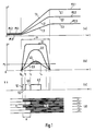
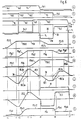
- the shape and amplitude of the detection signals which are generated in the processing circuits of the edge detectors depend on the nature of the detected signal edges, so that they trigger very different detection times on a switching edge with respect to the start of the switching edge. This leads to a flickering color edge that is perceived as annoying. This process is shown schematically in diagrams (a) to (d) of FIG. 1.
- Diagram (a) schematically shows the signal edges 1.1, 1.2 and 1.3 of three transmitted color signals 2.1, 2.2 and 2.3, each of which within a flank duration Tf from a level P1.1, P1.2 or P1.3 representing a color F1 a level representing a color F2 P2.1, P2.2 or P2.3 increase.
- Diagram (b) schematically shows the three associated bell-shaped detection signals 3.1, 3.2 and 3.3 of an edge detector (not described in more detail).
- the reference level Ps is drawn in the diagram (b), at which the part of a detector signal exceeding this reference level generates a switching signal shown in the diagram (c) at the output of a threshold switch of this detector arrangement.
- the part 4.3 of the detector signal 3.3 that exceeds the reference level Ps generates the switching signal 6.3. Since the three detection signals 3.1, 3.2 and 3.3 themselves have very different amplitudes and slope slopes, they pass through the reference level Ps of the detector arrangement on very different sides t1, t2 or t3, even though they start at the same starting time to. However, these latter different times determine switching edges 5.1, 5.2 and 5.3 for the detection time of the detected signal edges.
- diagram (d) there are schematically five video lines z1 to z5 of a video image with a vertical color edge K between the two areas with the color F1 to the left of the color edge and F2 to the right of the color edge K. The one caused by the different switching edges 5.1, 5.2 and 5.3 Jitter that changes continuously can be clearly seen in diagram (d).
- the invention has for its object to provide an arrangement specified in the preamble for the transmission of color television signals which contain a luminance signal and at least one color signal associated therewith in such a way that, in particular on the vertical color edges, there are no disturbing, incorrectly colored fringes and no disturbing color edge jitter.
- two identical, offset, but still overlapping difference signals are generated on the edge of the delayed signal to be detected.
- an edge difference signal is produced which oscillates definedly around a zero line and one in the area of overlap of the two individual signals in the middle of the edge difference signal Contains zero crossing at the steepest point of the signal. The position of the zero crossing is largely independent of the shape and the amplitude of the individual signals generated during the detection.
- the superimposed delayed and undelayed color signals do not result in a flattened image, but on the contrary, a lower-noise image with much less disturbed color areas.
- the image disturbances due to lower switching disturbances of the signal switch are lower, since the central position of the signal switch in normal operation means that the distance to the two signal states before and after the transition edge is at least smaller when switching off and in the idle state outside the color edge than in the prior art .
- the changeover device of the signal changeover switch is an electronic cross-fading potentiometer, which can be controlled directly or via an actuating signal amplifier by the edge difference signal generated by the edge detector arrangement.
- the compensation process for suppressing the faulty color fringe is easily adaptable to the type of transition on the signal flank from one signal state to the other signal state, so that little changes are made to the transmission process in the event of minor changes in state and thus there are also fewer disturbances due to this intervention in the transmission process are to be expected.
- the transmission of the color signal to detectable color signal edges is additionally detected. This ensures that the annoying color fringes on color edges that are not characterized by a jump in luminance and annoying jitter on these color edges are significantly reduced so that they no longer catch the eye.
- Another advantageous measure to include the result of a color edge detection in the removal of a disturbing color fringe on this color edge is to superimpose a certain proportion of the output signal of the color edge detection on the output signal of the detection of the associated luminance edge. As a result, the interference suppression of the color edge is adapted to the disturbance variables causing these disturbances.
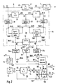
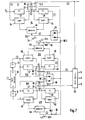
- Figure 2 shows a block diagram of an embodiment of an arrangement for transmitting color television signals for reproducing a color television image on a screen, not shown.
- the transmission arrangement is arranged, for example, in front of the frequency demodulator 7 in the playback part of a video recorder (not shown in more detail).
- the transmission arrangement contains a transmission path 8 with a delay line 9 for the transmission of the frequency-modulated luminance signal Ya of the color television signal and a transmission path 10 with a delay line 11, a signal switch 12 and an additional delay line 13 for transmission of the color signal FSf of the color television signal.
- the transmission path 10 for the color signal is connected to the output 15.2 of a bandpass 15, which is tuned to the color carrier frequency f (FT).
- the signal switch 12 contains three switch positions 12a, 12b and 12c, of which the middle switch position 12b is connected to the two outer switch positions 12a and 12c via two identical ohmic resistors 16.
- the first signal input 12.1 of the signal switch 12 connected to the outer switch position 12a is connected to the output 11.2 of the delay line 11 in the transmission path 10 of the color signal
- the second signal input 12.2 connected to the second outer switch position 12c of the signal switch is connected to the input 11.1 of this delay line 11 .
- the signal switch 12 contains a switch control 20, which generates an actuating signal 21 for setting the signal switch to the switch position 12a, 12b or 12c.
- An edge detector arrangement 24 as well as two threshold value switches 25a and 25c and a zero crossing detector 26 are connected between the input 9.1 of the delay line 9 in the transmission path 8 and the control inputs 20a to 20c of the switch control 20.
- the edge detector arrangement 24 essentially consists of the series connection of two delay lines 27 and 28, of which the input 27.1 of the first delay line 27 of the series circuit is connected to the input 9.1 of the delay line 9 in the transmission path 8, and a signal processing circuit 29 with two signal difference transmitters 30dl and 30d2 and a subtractor 31.
- the differential inputs of the first signal difference transmitter 30dl form the first Differential input pair 29.11 and 29.12 of the signal processing circuit 29 and the differential inputs of the second signal difference generator 30d2 form the second differential input pair 29.21 and 29.22 of the signal processing circuit.
- These differential inputs are connected via signal converters 32 to the inputs 27.1 and 28.1 and the outputs 27.2 and 28.2 of the two delay lines 27 and 28 of the edge detector arrangement 24 connected in series, in such a way that the first signal difference generator 30dl along the first delay line 27 and the second signal difference generator 30d2 along the second delay line 28 is arranged.
- the signal converters 32 serve to convert the signals Ya, Yb, Yc present at the inputs and outputs of the delay lines 27 and 28 into equivalent output signals, which are designed such that the signal difference transmitters 30d1 and 30d2 each one of the signal values of the equivalent output signals Form the difference of the signals Ya, Yb, or, Yb, Yc corresponding difference value and each generate a difference signal 32dl and 32d2 corresponding to this difference value at their signal output 30.3.
- the delay time Tvll of the delay line 11 in the transmission path 10 of the color signal FSf is dimensioned in the exemplary embodiment shown such that it is exactly an odd integer multiple of half the oscillation time T (FT) of the color carrier minus the running time of the inverter 14 connected in the illustrated exemplary embodiment of this delay line 11 and only is slightly longer than the largest expected edge duration T (SF) of the signal edges of the color signal causing the disturbing color fringe.
- Edge duration is understood to mean the duration of the time range of a signal edge that causes the visually visible, disturbing color fringe.
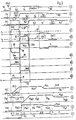
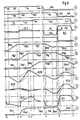
- Diagram (a) schematically shows a section of the undelayed frequency-modulated light density signal Ya at the input 9.1 of the delay line 9 in the transmission path 8 of this signal and at the input 27.1 of the first delay line 27 of the edge detector arrangement 24, the diagram (b) shows the luminance signal simply delayed by this delay line Yb at the output 27.2 of this delay line and the diagram (c) the luminance signal Yc delayed again by the second delay line 28 of the edge detector arrangement 24.
- the Undelayed luminance signal Ya contains a luminance jump SYa3 at time t0, at which the luminance signal jumps in a steeply rising signal edge Ya3 from a first signal state Ya1 representing a first luminance value to a second signal state Ya2 representing a second luminance value, and a second smaller luminance jump SYa4 at time t5 , at which the luminance signal Ya changes over a second signal edge Ya4 from the second signal state Ya2 into a third signal state Ya5 representing a third luminance value. Accordingly, the simply delayed luminance signal Yb at points t1 and t7 and the delayed luminance signal Yc at times t4 and t9 are obtained.
- the first signal difference generator 30dl forms a difference signal 32d1 at its output 30.3 from the difference between the undelayed luminance signal Ya from the output of the first signal converter 32 and the delayed luminance signal Yb from the output of the second signal converter 32 between the luminance jump SYa3 and the luminance jump SYb3 of the simply delayed luminance signal Yb. that is the image of the signal difference between the signal Ya at the input 27.1 and the simply delayed luminance signal Yb at the output 27.2 of the first delay line 27 of the edge detector arrangement 24.
- the second signal difference generator 28 forms a second difference signal 32d2 at its output 30.3 between the luminance jump SYb3 of the simply delayed luminance signal Yb from the output of the second signal converter 32 and the luminance jump SYc3 of the further delayed luminance signal Yc at the output of the third signal converter 32 of the edge detector arrangement 24.
- the two through the signal difference transmitter 30dl and 30d2 Signal difference signals 32d1 and 32d2 generated are shown in the diagrams (d1) and (d2) of FIG.
- the signal difference transmitters 30d1 and 30d2 are designed such that they only output the signal difference signals they form at their signal output 30.3 in one polarity direction, in the exemplary embodiment shown only in the electrically positive polarity direction. Due to the way in which the two signal difference signals 32d1 and 32d2 are generated, these two signals overlap in time in the region 33 of the edge rise time T (FSL3).
- the subtractor 31 subtracts the two identical signals, so that at its signal output, which represents the detection output 24.3 of the edge detection arrangement 24 shown in FIG. 2, an edge difference signal 34.1 and in the area of the second luminance jump SYb4 of the delayed luminance signal Yb, a second edge difference signal 34.2 is generated both are shown in diagram (d) of FIG. 3.
- Both edge difference signals 34.1 and 34.2 oscillate around a zero line 35 with a first oscillation 34a which is negatively directed in the illustrated embodiment and with a subsequent second oscillation 34b which is positively directed in the illustrated embodiment and pass through the zero line in the middle t2 of the overlap region 33 of the two signal difference signals 32d1 and 32d2 with a zero crossing 36.
- This zero crossing is on the one hand at the steepest point of the edge difference signal 34.1 and on the other hand, temporally in the middle of the signal edge of the luminance jump SYb3 of the simply delayed luminance signal Yb and thus defines the detection time t2 of the luminance jump SYb3 of the delayed luminance signal at the output 27.2 of the first delay line 27 of the edge detection arrangement 24.
- a threshold switch 25a and 25c is connected to the signal output 30.3 of the signal difference transmitters 30dl and 30d2, the switching level Ps of which is shown in the diagrams (dl) and (d2) in FIG. 3 by a dashed line 37. If the level of the signal difference signals 32dl and 32d2 exceeds the switching level Ps of the threshold switches represented by line 37, they generate a switching signal 38d4 and 38d5 at their output 25.1 during the time of exceeding, which is shown in diagrams (d4) and (d5) of FIG. 3 is shown schematically.
- the zero crossing detector 26 at the output of the subtractor 31 generates a switching edge 39.1 of a switching signal 39 in the zero crossing 36 of the edge difference signal 34.1 supplied to it, which is shown schematically together with the switching edge 39.1 in diagram (d3) of FIG. 3. From these three switching signals 38d4, 38d5 and 39, the switch control 20 of the signal switch 12 generates an actuating signal 21, which is shown in the diagram (d6) of FIG.
- a first actuating level P1 and during of the switching signal 38d5 of the second signal difference generator 30d2 has a second actuating level P2 and jumps from the first actuating level P1 to the second actuating level P2 on the switching edge 39.1 of the switching signal 39 of the zero crossing detector 26 and outside of these two switching signals 38d4 and 38d5 has the setting level 0, at which the signal switch is set to the middle switching position 12b.
- the first control level P1 places the signal switch 12 in the first outer switch position 12a, in which the output 12.3 of the signal switch is connected to the output of the delay line 11 of the transmission path 10 for the color signal.
- the second control level P2 places the signal switch 12 in the second switch position 12c, in which the output 12.3 of the signal switch is connected to the input of this delay line 11.
- the luminance jump SYa4 between the signal states Ya2 and Ya5 of the undelayed luminance signal Ya and the delayed luminance signals Yb and Yc is so small that the level of the signal difference signals 32d1.1 and 32d2.1 generated therefrom in the edge detector arrangement 24 corresponds to the switching level Ps of the threshold switches 25a and 25c do not reach and therefore no switching signals are generated at the output of the threshold switches 25a and 25c.
- the edge difference signal 34.2 generated at the output of the subtractor 31 from the signal difference signals 32d1.1 and 32d2.1 does not come into effect in the switch control 20 of the signal switch 12.
- FIG 3 shows a section of the undelayed color signal FSf associated with the undelayed luminance signal Ya, which is present at the second signal input 12.2 of the signal switch 12, while in diagram (g) that which is delayed by the delay line 11 and at the first signal input 12.1 of the signal switch 12 applied color signal FSg is shown in sections.
- the undelayed Color signal FSf has a first signal edge FSf3, in which the color signal changes in an edge rise time T (SF3) from a signal state FSf1 representing a first color type F1 to a signal state FSf2 representing a second color type F2, and that of the first signal edge Ya3 of the in the diagram (a ) is assigned to the luminance signal Ya shown, and a second signal edge FSf4, on which the color signal FSf changes from the signal state FSf2 to a signal state FSf5 representing the color type F3 and which belongs to the signal edge Ya4 of the luminance signal Ya at the point t6.
- T edge rise time
- the curve of the delayed color signal FSg shown in diagram (g), which is offset by the delay time Tv11 from the undelayed color signal FSf, is designed accordingly.
- the rise time T (SF3) of the signal edge FSf3 is significantly greater than the rise time T (SFL3) of the associated signal edge Ya3 of the undelayed luminance signal Ya.
- the signal edge Ya3 of the undelayed luminance signal Ya is timed with respect to the associated signal edge FSf3 of the undelayed color signal FSf so that the center of the signal edge of the luminance signal is temporally on the center of the associated signal edge of the undelayed color signal.
- the delay time Tv13 of the delay line 13 at the output 15.2 of the bandpass 15 is dimensioned such that the signal edge FSf3 of the undelayed color signal FSf is delayed to the extent that the end of the largest expected rise time T (SF3) immediately before the zero crossing 36 at the time t2 of the edge difference signal 34.1 generated by the edge detection arrangement 24.
- the delay time Tv27 of the first delay line 27 of the edge detection arrangement 24 is greater than the expected greatest rise time T (SF3) of a color edge of the color signal FSf, so that the oscillation 34a lying before the zero crossing 36 is always wider in time than the disturbing color fringe.
- Diagram (s) schematically shows the curve of the transmitted color signal FSn at the signal output 12.3 of the signal switch 12.
- the signal output is the fact that the signal switch is set to its first outer switching position 12a by the switching signal 21 before the start of the signal edge FSf3 of the instantaneous color signal FSf in its first outer switching position 12a 12.3 of the signal switch 12 is connected to the output of the delay line 11 in the transmission path of the color signal and transmits the first signal state FSg1 of the delayed color signal FSg representing the first color type F1 until the time t2 of the zero crossing 36 of the edge difference signal 34.1 at the output 24.3 of the edge detection arrangement 24 of the control level of the control signal 21 of the switch control 20 changes from the level value P1 to the second level value P2 and thus switches the signal switch 12 into the second outer switching position 12c.
- the state of the color signal FSn transmitted at the signal output 12.3 of the signal switch changes from the first signal state FSn1 representing the first color type F1 to the second signal state FSn2 representing the second color type F2 with a very steep signal edge FSn3 with the switching speed of the signal switch 12.
- the signal switch 12 is returned to its middle switching position 12b, in which it remains until a next control signal.
- the color signal FSn at the signal output of the signal switch occurs in a weakened form both in the range of second signal edge FSn4 of the undelayed color signal FSf and also in the time domain of the second signal edge FSg4 of the delayed color signal FSg a signal edge.
- the color changes at these two color edges FSn4 and FSn6 are generally so small that they are not noticeable.
- the disturbing signal edge FSf3 of the color signal which generates a color fringe is, however, distributed by switching the transmission at the signal switch 12 such that it forms a sharp color edge without color fringe on the reproduced color image.
- the delay time Tv9 of the delay line 9 in the transmission path 8 of the luminance signal Yn is dimensioned such that the associated luminance edge Yn3 is located temporally at the location of the distributed color edge FSn3, as is shown schematically in diagram (n1) in FIG.
- the switchover of the signal switch 12 from the first outer switch position 12a to the second outer switch position 12c and thus the color jump of the color signal at the signal output 12.3 of the signal switch 12 from the signal state FSnl to the signal state FSn2 always takes place at the time t2 of the zero crossing 36 of associated edge difference signals 34.1 at the output 24.3 of the edge detector arrangement 24.
- This zero crossing is independent of the shape of the signal difference signals 32d1 and 32d2 formed at the signal difference transmitters, as shown schematically in diagram (a) of FIG. There are three different differential signal pairs 32d1a to 32d2c and the edge difference signals 34.la to 34.lc formed therefrom in the subtractor 31.
- the center of the overlap area 40 of a differential signal pair is always at the same time t2 of a picture line and the zero crossing 36 of each edge difference signal 34.1a to 34.1c formed from the differential signal pairs is also in the middle of the Overlap area 40 and thus regardless of the shape and amplitude of the edge difference signals of a color edge at the same time point t2.
- the exemplary embodiment of an arrangement for transmitting color television signals and for eliminating a disturbing color fringe along a particularly vertical color edge in addition to an edge detection arrangement 24 for detecting signal edges in the luminance signal of the color television signal, also contains a color signal edge detection arrangement 41.
- the first delay line 27 of the edge detection arrangement 24 for detecting luminance edges is at the same time the delay line in the transmission path 8.
- a section of the undelayed luminance signal Ya is shown in diagram (a) in FIG.
- the luminance signal Ya is also an FM signal in the exemplary embodiment shown.
- FM demodulators 42 and 43 with a non-inverted and an inverted signal output 44 serve as signal difference transmitters.
- the signal inputs 46.1 and 46.2 of the signal adder 46 are supplied with differential signals 32dl and 32d2 of opposite polarity, so that the signal addition within the signal adder 46 corresponds to a subtraction of the differential signals supplied by the FM demodulators 42 and 43.
- the signal output of the signal adder 46 which is also the detection output 24.3 of the edge detection arrangement 24, supplies an edge difference signal 34.1 or 34.2 generated by the signal addition, which is shown schematically in diagram (d) of FIG.
- the color signal edge detection arrangement 41 also contains the series connection of a first delay line 47 and a second delay line 48, of which the first delay line 47 is arranged in the transmission path 10 of the color signal at the same time for delaying the color signal FSf.
- the delay time Tv47 of the first delay line 47 of the color signal edge detection arrangement 41 is an odd integer multiple of half the oscillation period T (FT) of the color carrier, so that the color carrier vibrations at the output 47.2 and at the input 47.1 of the first delay line 47 are in phase with one another.
- T (FT) of the color carrier is an odd integer multiple of half the oscillation period T (FT) of the color carrier
- the 6 contains a section of the undelayed color signal FSf at the output of the bandpass filter 15 corresponding to the section of the luminance signal Ya shown in the diagram (a), the diagram (g) shows the time delay by the delay time Tv47 of the first delay line 47, the signal section shown in diagram (f) and diagram (h) the section of the signal section of the color signal FSf shown in diagram (f), which is again offset in time by the delay time of the second delay line 48.
- the delay time Tv47 of the first delay line 47 is also dimensioned such that it is slightly longer than the largest expected rise time T (FS3) of a signal edge of the color signal FSf.
- differential amplifiers 49 and 50 with one non-inverted and one inverted signal output 51 serve as signal difference transmitters of the color signal edge detection arrangement 41.
- the opposite polarity signal outputs of the first differential amplifier 49 are Via rectifiers 52 of a certain same polarity direction to the first signal input 53.1 of a signal adder 53 and the oppositely polarized signal outputs 51 of the second differential amplifier 50 are connected to the second signal input 53.2 of the signal adder via rectifiers 54 which are oppositely polarized to the first rectifiers.
- the differential amplifiers 49 and 50 in conjunction with their output-side rectifiers 52 and 54, in turn supply pairs of differential color signals 55.1a and 55.1b, which are shown in diagram (i) of FIG.
- the signal adder 53 forms the associated color edge difference signal 57.1 which oscillates around a zero line 35 and passes through it in a zero crossing 36, as shown in diagram (i).
- the signal changeover switch 12 contains an electronic cross-fade potentiometer 60, the tap 60.0 of which is connected to the signal output 12.3 of the signal switch and the signal inputs 60.1 and 60.2 the ends of the tapped resistance of the electronic cross-fade potentiometer 60 with the input 47.1 and that Connect output 47.2 of the first delay line 47 of the color signal edge detection arrangement 41.
- the signal switch 12 contains a controller control 18 with a priority switch 19, which connects the first input 18.1 of the controller control 18 as long as the signal output 53.3 of the signal adder 53 of the color signal edge detection arrangement 41 an edge difference signal 34.2 does not reach and exceed a certain switching level Ps, which is indicated in diagram (d).
- the second input 18.2 of the controller control 18 is connected to its detection output 24.3 for the duration of the edge difference signal 34.1 of the edge detector arrangement 24 for the detection of luminance signal edges.
- the tapper 60.4 of the electronic cross-fade potentiometer is thereby initially displaced from the center position to the second signal input 60.2 of the electronic potentiometer, to which the color signal shown in diagram (g), delayed by the first delay line 47, is fed, so that the first, representing a first color type F1 Signal state FSg1 remains approximately unchanged, and then during the rising period of the signal edge FSg3 of the delayed color signal FSg into the other distortion of the electronic potentiometer 60 connected to the first signal input 60.1 set.
- the color signal FSn shown in the diagram (s) in a relatively rapid rise FSn3 reaches the signal state FSn2 representing a second color type F2, because of the predominantly increasing proportion of this signal state.
- the second luminance signal edge Ya4 of the undelayed luminance signal Ya on the second color edge is such that the edge detection signal 34.1 generated in the edge detection arrangement 24 for detection of this luminance edge Ya4 exceeds the switching level Ps in the controller control 18 and the priority switch 19 of the controller control at the detection output 24.3 of the edge detection 24 switches for the detection of a luminance flank for the duration of the flank difference signal at the detection output 24.3, as represented in the diagram (1) by the priority signal 61.
- the edge difference signal 34.1 of the edge detector arrangement 24 comes into effect as a control signal 22.1 for the electronic cross-fading potentiometer 60.
- the tap 60.4 of the potentiometer is first connected to the end position connected to the second signal input 60.2 for the delayed color signal FSg and at the time of the zero crossing 36 of the edge difference signal 34.1 at the speed of the zero crossing from the mentioned end position to the other, connected to the first signal input 60.1 Adjusted end position, which is supplied with the undelayed color signal FSf.
- the electronic cross-fading potentiometer 60 is set to a center setting in which approximately equal portions of the undelayed color signal FSf and the delayed color signal FSg arrive at the output of the transmission path 10 for the color signal in a superimposed manner. This superimposition reduces the surface noise in the color image display without the color image display as such being falsified. In the event of color changes, the electronic fade-in potentiometer 60 is adjusted smoothly and not suddenly, so that no switching faults occur as a result.
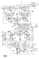
- the exemplary embodiment of an arrangement for transmitting color television signals and for eliminating disturbing color fringes on vertical color edges shown in FIG. 7 contains a transmission path 8 for transmitting a luminance signal Ya of a color television signal and two similar transmission paths 10U and 10V for transmitting a color signal U and a color signal V.
- it is the transmission paths of the color signals U and V between a color decoder 62 and an RGB matrix 63 of a color television receiver.
- an edge-enhanced luminance signal Ye is fed to the RGB matrix.
- All three transmission paths 8, 10U and 10V each contain a signal switch 12, the switching device of which is an electronic fade potentiometer 60, accordingly the embodiment shown in Figure 5.
- this edge detection arrangement 24 contains two delay lines 27 and 28 connected in series, of which the first delay line 27 is at the same time the delay line of the transmission path 8 of the luminance signals.
- the input side of subtractors 64 are connected to them, in accordance with the previously illustrated exemplary embodiments, which each form a signal difference signal of opposite polarity directions from the input and output signals of the assigned delay line and feed an adder 46 to generate an edge difference signal.
- This edge difference signal 34 is fed directly to the signal change-over switches 12 via decoupling circuits 65 and 66 as a control signal.
- the luminance signals shown in diagrams (a) to (c) show the same course as in diagrams (a) to (c). 6, so that the diagrams (d) of the two FIGS. 6 and 8 also correspond with the edge difference signal 34 shown therein, which is formed from the undelayed and the delayed luminance signals Ya, Yb and Yc.
- the signals shown in the diagrams (f) to (i) of the same name also correspond, namely the undelayed color signal FSf, the two delayed color signals FSh and FSg, and the edge difference signal 57 formed therefrom. so that it is no longer necessary to go into these signals.
- the signal switch 12 in the transmission path 8 Under the effect of the edge detection signal 34 formed as an actuating signal at the output 24.3 of the edge detection arrangement 24 connected to the transmission path 8 of the luminance signal, the signal switch 12 in the transmission path 8 generates a luminance signal Ye at its signal output 12.3 from the undelayed luminance signal Ya and the delayed luminance signal Yb Diagram (e) of FIG. 8 is shown, and that at the luminance flanks is significantly more distributed than the signal flanks of the delayed luminance signal Yb shown in diagram (b) by the switching speed of the signal switch 12 in the transmission path of the luminance signals. This results in a much sharper image reproduction.
- both transmission paths of the color signals U and V contain an edge detection arrangement 41U and 41V, both of which correspond, for example, to the detection arrangement of the exemplary embodiment illustrated in FIG. 5 and are therefore identified by the same reference numerals.
- the diagram (k) of FIG. 8 shows the curve of the edge difference signals 57.2V and 57.1V for the color signal edges at the corresponding luminance edges Yb3 and Yb4 of the delayed luminance signal Yb for the transmission path of the second color signal V.
- the edge detection signals 57U and 57V shown in the diagrams (i) and (k) are compared with the attenuation in the diagram (d) with a certain attenuation set by the resistors 67 and 68. edge difference signal shown at the output of the decoupling circuit 65 superimposed.
- the decoupling circuit 66 forms, together with the resistors 67 and 68, a combination circuit in which the superimposition is effected and at whose signal outputs 69 an actuating signal 21 shown in the diagram (m) for setting the electronic cross-fading potentiometer 60 in the transmission paths 10U and 10V of this superimposition two color signals U and V is generated.
- the color signal FSu formed by the adjustment of the electronic fade potentiometer 60 in the transmission path 10U of the first color signal U is shown schematically in the diagram (s).
Abstract
Description
Die Erfindung betrifft eine Anordnung zur Übertragung von Farbfernsehsignalen, die ein Leuchtdichtesignal und wenigstens ein diesem zugeordnetes Farbsignal enthalten gemäß dem im Oberbegriff des Anspruches 1 angegebenen Text.The invention relates to an arrangement for the transmission of color television signals which contain a luminance signal and at least one color signal associated therewith in accordance with the text specified in the preamble of
EP-A-0 302 500 offenbart eine solche Anordnung.EP-A-0 302 500 discloses such an arrangement.
Bei der Übertragung von Farbfernsehbildern wird im allgemeinen die Farbinformation eines Farbfernsehbildes getrennt von der Leuchtdichteinformation übertragen, insbesondere um die Kompatibilität zur Schwarz-Weiß-Übertragung eines derartigen Fernsehbildes zu wahren. Der Übertragung der Farbsignale für eine derartige Farbinformation steht hierbei eine wesentlich geringere Frequenzbandbreite zur Verfügung als der Übertragung der zugehörigen Leuchtdichtesignale. Hinzu kommt, daß bei der Übertragung der Farbfernsehbilder das Farbsignal den Übertragungsmodus häufiger wechselt als das zugehörige Leuchtdichtesignal. Dadurch ist das Farbsignal innerhalb einer Übertragung eines Farbfernsehbildes häufiger Störstellen innerhalb des Übertragungsweges ausgesetzt als das Leuchtdichtesignal. Diese Störstellen verflachen darüber hinaus insbesondere sprunghafte Änderungen der übertragenen Farbinformation im Übertragungsweg wegen der wesentlich geringeren Übertragungsbandbreite erheblich mehr als im Übertragungsweg des Leuchtdichtesignals die entsprechenden Leuchtdichtesprünge verflacht werden. Die Verflachung ursprünglich sprungartiger Farbübergänge mit einem großen Farbartunterschied verursachen insbesondere an einer senkrechten Farbkante des Originalbildes einen gestörten Farbübergang, der in der Gestalt eines verhältnismäßig breiten, störenden Farbsaumes auftritt und dessen Farbe zwischen der Farbart der beiden an der Sprungkante aneinandergrenzenden Farbflächen liegt. Außerdem ist dieser störende Farbsaum meistens einseitig neben der originalen Farbsprungkante angeordnet, so daß ein verzerrtes, oft deutlich neben den Leuchtdichtekonturen liegendes Farbbild wiedergegeben wird.When transmitting color television images, the color information of a color television image is generally transmitted separately from the luminance information, in particular in order to maintain compatibility with the black and white transmission of such a television image. The transmission of the color signals for such color information has a significantly smaller frequency bandwidth available than the transmission of the associated luminance signals. In addition, when the color television images are transmitted, the color signal changes the transmission mode more frequently than the associated luminance signal. As a result, the color signal within a transmission of a color television picture is more frequently exposed to interference points within the transmission path than the luminance signal. These defects also flatten out sudden changes in the transmitted color information in the transmission path because of the significantly lower transmission bandwidth than the corresponding luminance jumps are flattened in the transmission path of the luminance signal. The flattening of originally jump-like color transitions with a large difference in color type causes, particularly on a vertical color edge of the original image, a disturbed color transition which occurs in the form of a relatively wide, disturbing color fringe and whose color lies between the color type of the two color areas adjoining at the jump edge. In addition, this annoying color fringe is usually arranged on one side next to the original color jump edge, so that a distorted color image, which is often clearly adjacent to the luminance contours, is reproduced.
Aus der technischen Information TI 891023 der Firma Philips mit dem Titel "Die Schaltung TDA 4670 zur Bildsignal-Nachverarbeitung im Fernsehempfänger" ist eine Schaltung zur Beseitigung der eben beschriebenen Fehlfarben im Farbsaum einer senkrechten Farbkante bekannt, die in den Farbdifferenz-Übertragungskanälen eines Farbfernsehers differenzierende Flankendetektoren einer Flankendetektoranordnung enthält. Jeder Flankendetektor erzeugt an seinem Ausgang ein von der Art der detektierten Signalflanke abhängiges Detektorsignal, das in einem nachfolgendem Impulsformer der Anordnung nochmals differenziert und danach einem Schaltkreis mit einer eingestellten Schaltschwelle zugeführt wird. Die so erzeugten Schaltsignale der Flankendetektoranordnung steuern einen Analogschalter in der Übertragungsleitung, an dessen Ausgangsseite ein Speicherkondensator angeschlossen ist. Während der Dauer des Schaltsignales der Flankendetektoranordnung ist der Analogschalter unterbrochen, so daß während des unterbrochenen Zustandes des Analogschalters der Speicherkondensator den Pegel des ausgangsseitigen Übertragungskanals bestimmt und das Übertragungssignal so lange auf dem zuletzt vor dem Öffnen des Analogschalters anliegenden Pegel hält. Nach dem Wiederschließen des Analogschalters, d. h. nach dem Ende der Signalflanke verändert sich das Signal auf der ausgangsseitigen Übertragungsleitung mit der verhältnismäßig kurzen Ladezeit des Speicherkondensators auf den Pegel des Signalzustandes nach der Signalflanke, so daß die Steilheit der korrigierten Signalflanke nur noch von der kurzen Ladezeit des Speicherkondensators abhängig ist. Es hat sich jedoch gezeigt, daß in vielen Fällen, insbesondere wenn ein Videorekorder an den Fernseher angeschlossen ist, die störenden fehlfarbigen Farbsäume an senkrechten Farbkanten nicht beseitigt sind und weiterhin ein gestörtes flaues Farbbild auf dem Bildschirm des Fernsehers wiedergegeben wird.From the technical information TI 891023 from Philips with the title "The circuit TDA 4670 for image signal post-processing in television receivers" a circuit for eliminating the above-described false colors in the color fringe of a vertical color edge is known, which differentiates in the color difference transmission channels of a color television edge detectors contains an edge detector arrangement. Each edge detector generates at its output a detector signal which is dependent on the type of the detected signal edge and which differentiates again in a subsequent pulse shaper of the arrangement and is then fed to a circuit with a set switching threshold. The switching signals of the edge detector arrangement thus generated control an analog switch in the transmission line, to the output side of which a storage capacitor is connected. The analog switch is interrupted during the duration of the switching signal of the edge detector arrangement, so that during the interrupted state of the analog switch, the storage capacitor determines the level of the transmission channel on the output side and keeps the transmission signal at the level last present before the analog switch was opened. After the analog switch is closed again, i.e. after the end of the signal edge, the signal on the output transmission line changes with the relatively short charging time of the storage capacitor to the level of the signal state after the signal edge, so that the steepness of the corrected signal edge only depends on the short charging time of the Storage capacitor is dependent. However, it has been shown that in many cases, especially when a video recorder is connected to the television, the annoying false color fringes on vertical color edges have not been eliminated and a disturbed, fluffy color image is still displayed on the television screen.
In DE-A-41 32 508, veröffentlicht 01.04.93, ist eine Übertragungsanordnung zur Übertragung von Farbfernsehsignalen für die Wiedergabe eines Farbfernsehbildes auf einem Bildschirm vorgeschlagen, bei der sowohl im Übertragungsweg des Leuchtdichtesignals als auch im Übertragungsweg des zugehörigen Farbsignales der Farbfernsehsignale eine Verzögerungsleitung angeordnet ist. Der Übertragungsweg der Farbsignale enthält außerdem einen Signalumschalter, dessen Signalausgang in der einen Schaltstellung des Signalumschalters mit dem Ausgang der Verzögerungsleitung und in der anderen Schaltstellung des Signalumschalters mit dem Eingang der Verzögerungsleitung verbunden ist. Der Signalumschalter wird sowohl von einem das Farbsignal detektierenden Farbkantendetektor als auch von einem das Leuchtdichtesignal detektierendem Leuchtdichtesprungdetektor gesteuert. Ist kein Farbsprung oder Leuchtdichtesprung erkannt, wird das FBAS-Ausgangssignal aus dem verzögerten Farbsignal und dem verzögerten Leuchtdichtesignal gebildet. Während der Erkennung eines Farb- oder Leuchtdichtesprunges wird der Signalausgang des Signalumschalters während der Übertragung des verzögerten Farbsprunges auf den Eingang der Verzögerungsschaltung im Übertragungsweg des Farbsignales geschaltet, an dem bereits das neue Farbsignal hinter dem Farbsprung liegt.In DE-A-41 32 508, published April 1, 1993, a transmission arrangement for the transmission of color television signals for the reproduction of a color television picture on a screen is proposed, in which a delay line is arranged both in the transmission path of the luminance signal and in the transmission path of the associated color signal of the color television signals is. The transmission path of the color signals also contains a signal switch, the signal output of which is connected to the output of the delay line in one switch position of the signal switch and to the input of the delay line in the other switch position of the signal switch. The signal switch is controlled both by a color edge detector which detects the color signal and by a luminance jump detector which detects the luminance signal. Is not a jump in color or luminance jump detected, the CVBS output signal is formed from the delayed color signal and the delayed luminance signal. During the detection of a color or luminance jump, the signal output of the signal switch is switched during the transmission of the delayed color jump to the input of the delay circuit in the transmission path of the color signal, on which the new color signal is already behind the color jump.
Der fehlfarbige Störstreifen an einer senkrechten Farbkante ist zwar durch die soeben beschriebenen Maßnahmen weitgehend beseitigt. Jedoch weist die Farbkante weiterhin einen störenden Jitter auf, der die Farbkante störend unruhig macht. Diese Störung ist besonders stark bei ziemlich verrauschten Farbfernsehsignalen oder wenn das Farbfernsehsignal von einer Farbart über eine verhältnismäßig flache Signalflanke in eine andere Farbart übergeht und die Steilheit der Signalflanke der dargestellten Farbkante von Zeile zu Zeile schwankt. Die Detektionssignale, die in den Verarbeitungsschaltungen der Flankendetektoren erzeugt werden, sind in ihrer Gestalt und ihrer Amplitude von der Beschaffenheit der detektierten Signalflanken abhängig, so daß sie an einer Schaltflanke bezüglich des Beginns der Schaltflanke sehr unterschiedliche Detektionszeitpunkte auslösen. Dies führt zu einer flimmernd bewegten Farbkante, die als störend empfunden wird. Dieser Vorgang ist schematisch in den Diagrammen (a) bis (d) der Figur 1 dargestellt. Im Diagramm (a) sind schematisch die Signalflanken 1.1, 1.2 und 1.3 dreier übertragener Farbsignale 2.1, 2.2 und 2.3 dargestellt, die jeweils innerhalb einer Flankendauer Tf von einem eine Farbe F1 darstellenden Pegel P1.1, P1.2 bzw. P1.3 auf einen eine Farbe F2 darstellenden Pegel P2.1, P2.2 bzw. P2.3 ansteigen. Im Diagramm (b) sind schematisch die drei zugehörigen glockenförmigen Detektionssignale 3.1, 3.2 und 3.3 eines nicht näher beschriebenen Flankendetektors dargestellt. Außerdem ist im Diagramm (b) der Bezugspegel Ps eingezeichnet, bei dem der diesen Bezugspegel überschreitende Teil eines Detektorsignals am Ausgang eines Schwellwertschalters dieser Detektoranordnung ein im Diagramm (c) dargestelltes Schaltsignal erzeugt. Im dargestellten Ausführungsbeispiel erzeugt der den Bezugspegel Ps überschreitende Teil 4.3 des Detektorsignals 3.3 das Schaltsignal 6.3. Da die drei Detektionssignale 3.1, 3.2 und 3.3 selbst sehr unterschiedliche Amplituden und Flankensteigungen aufweisen, durchlaufen sie zu sehr unterschiedlichen Seiten t1, t2 oder t3 den Bezugspegel Ps der Detektoranordnung, obwohl sie am gleichen Anfangszeitpunkt to beginnen. Diese letztgenannten unterschiedlichen Zeitpunkte legen jedoch die Schaltflanken 5.1, 5.2 und 5.3 für den Detektionszeitpunkt der detektierten Signalflanken fest. Im Diagramm (d) sind schematisch fünf Videozeilen z1 bis z5 eines Videobildes mit einer senkrechten Farbkante K zwischen den beiden Flächen mit der Farbe F1 links von der Farbkante und F2 rechts von der Farbkante K. Der durch die unterschiedlichen Schaltflanken 5.1, 5.2 und 5.3 hervorgerufenen Jitter, der sich dauernd ändert, ist im Diagramm (d) deutlich zu erkennen.The false-colored interference stripe on a vertical color edge is largely eliminated by the measures just described. However, the color edge still has an annoying jitter, which makes the color edge disturbing. This disturbance is particularly severe in the case of fairly noisy color television signals or when the color television signal changes from one color type via a relatively flat signal edge to another color type and the slope of the signal edge of the color edge shown fluctuates from line to line. The shape and amplitude of the detection signals which are generated in the processing circuits of the edge detectors depend on the nature of the detected signal edges, so that they trigger very different detection times on a switching edge with respect to the start of the switching edge. This leads to a flickering color edge that is perceived as annoying. This process is shown schematically in diagrams (a) to (d) of FIG. 1. Diagram (a) schematically shows the signal edges 1.1, 1.2 and 1.3 of three transmitted color signals 2.1, 2.2 and 2.3, each of which within a flank duration Tf from a level P1.1, P1.2 or P1.3 representing a color F1 a level representing a color F2 P2.1, P2.2 or P2.3 increase. Diagram (b) schematically shows the three associated bell-shaped detection signals 3.1, 3.2 and 3.3 of an edge detector (not described in more detail). In addition, the reference level Ps is drawn in the diagram (b), at which the part of a detector signal exceeding this reference level generates a switching signal shown in the diagram (c) at the output of a threshold switch of this detector arrangement. In the exemplary embodiment shown, the part 4.3 of the detector signal 3.3 that exceeds the reference level Ps generates the switching signal 6.3. Since the three detection signals 3.1, 3.2 and 3.3 themselves have very different amplitudes and slope slopes, they pass through the reference level Ps of the detector arrangement on very different sides t1, t2 or t3, even though they start at the same starting time to. However, these latter different times determine switching edges 5.1, 5.2 and 5.3 for the detection time of the detected signal edges. In diagram (d) there are schematically five video lines z1 to z5 of a video image with a vertical color edge K between the two areas with the color F1 to the left of the color edge and F2 to the right of the color edge K. The one caused by the different switching edges 5.1, 5.2 and 5.3 Jitter that changes continuously can be clearly seen in diagram (d).
Der Erfindung liegt die Aufgabe zugrunde, eine im Oberbegriff angebene Anordnung zur Übertragung von Farbfernsehsignalen, die ein Leuchtdichtesignal und wenigstens ein diesem zugeordnetes Farbsignal enthalten, derart auszubilden, daß insbesondere an den senkrechten Farbkanten keine störenden, fehlfarbigen Farbsäume und kein störendes Farbkantenjitter auftritt. Diese Aufgabe wird nach der Erfindung durch die im kennzeichnenden Teil des Anspruches 1, dessen Text Bestandteil dieser Beschreibung ist, gelöst.The invention has for its object to provide an arrangement specified in the preamble for the transmission of color television signals which contain a luminance signal and at least one color signal associated therewith in such a way that, in particular on the vertical color edges, there are no disturbing, incorrectly colored fringes and no disturbing color edge jitter. This task is solved according to the invention by the in the characterizing part of
Mit den Mitteln der Erfindung werden einerseits in einfacher Weise an der zu detektierenden Flanke des verzögerten Signales zwei gleichgestaltete, versetzte, sich aber noch überlappende Differenzsignale erzeugt. Durch die Subtraktion der beiden sich überlappenden Detektionssignale in einer Subtrahieranordnung oder durch eine Addition der beiden sich überlappenden, zueinander invertierten Differenzsignale in einer Addieranordnung entsteht ein Flankendifferenzsignal, das definiert um eine Nullinie schwingt und im Bereich der Überlappung der beiden Einzelsignale in der Mitte des Flankendifferenzsignales einen Nulldurchgang an der steilsten Stelle des Signales enthält. Die Lage des Nulldurchganges ist weitgehend unabhängig von der Gestalt und der Amplitude der bei der Detektion entstehenden Einzelsignale.With the means of the invention, on the one hand, two identical, offset, but still overlapping difference signals are generated on the edge of the delayed signal to be detected. By subtracting the two overlapping detection signals in a subtracting arrangement or by adding the two overlapping, mutually inverted difference signals in an adding arrangement, an edge difference signal is produced which oscillates definedly around a zero line and one in the area of overlap of the two individual signals in the middle of the edge difference signal Contains zero crossing at the steepest point of the signal. The position of the zero crossing is largely independent of the shape and the amplitude of the individual signals generated during the detection.
Andererseits entsteht außerhalb einer Farbkante nicht, wie man erwarten könnte, durch die Überlagerung der verzögerten und der unverzögerten Farbsignale bei der Bildwiedergabe ein verflachtes Bild, sondern im Gegenteil, ein rauschärmeres Bild mit wesentlich weniger gestörten Farbflächen. An den Farbkanten sind die Bildstörungen durch geringere Umschaltstörungen des Signalschalters geringer, da durch die Mittenstellung des Signalschalters im Normalbetrieb der Abstand zu den beiden Signalzuständen vor und nach der Übergangsflanke wenigstens beim Schalten aus und in den Ruhezustand außerhalb der Farbkante geringer ist als beim Stand der Technik.On the other hand, outside of a color edge, as is not to be expected, the superimposed delayed and undelayed color signals do not result in a flattened image, but on the contrary, a lower-noise image with much less disturbed color areas. At the color edges, the image disturbances due to lower switching disturbances of the signal switch are lower, since the central position of the signal switch in normal operation means that the distance to the two signal states before and after the transition edge is at least smaller when switching off and in the idle state outside the color edge than in the prior art .
Die Unteransprüche kennzeichnen vorteilhafte Ausgestaltungen und Weiterbildungen der Erfindung. Der Text dieser Unteransprüche ist Bestandteil dieser Beschreibung.The subclaims characterize advantageous refinements and developments of the invention. The text of these subclaims forms part of this description.
In einer besonders vorteilhaften Ausgestaltung der Erfindung ist die Umschalteinrichtung des Signalumschalters ein elektronisches Überblendpotentiometer, das unmittelbar oder über einen Stellsignalverstärker von dem von der Flankendetektoranordnung erzeugten Flankendifferenzsignal gesteuert werden kann. Dadurch entfällt erstens eine Steuerung des Signalumschalters durch Schaltvorgänge, die stets mit Schaltstörungen auf dem Übertragungsweg der geschalteten Signale verbunden sind. Zum zweiten ist der Ausgleichvorgang zur Entstörung des fehlfarbigen Farbsaums leicht der Art des Überganges an der Signalflanke von einem Signalzustand zum anderen Signalzustand anpassbar, so daß bei kleineren Zustandsänderungen nur wenig in den Übertragungsablauf eingegriffen wird und damit dort auch geringere Störungen durch diesen Eingriff in den Übertragungablauf zu erwarten sind.In a particularly advantageous embodiment of the invention, the changeover device of the signal changeover switch is an electronic cross-fading potentiometer, which can be controlled directly or via an actuating signal amplifier by the edge difference signal generated by the edge detector arrangement. First of all, this means that there is no control of the signal switch by switching processes which are always associated with switching faults on the transmission path of the switched signals. Secondly, the compensation process for suppressing the faulty color fringe is easily adaptable to the type of transition on the signal flank from one signal state to the other signal state, so that little changes are made to the transmission process in the event of minor changes in state and thus there are also fewer disturbances due to this intervention in the transmission process are to be expected.
In einer weiteren vorteilhaften Ausgestaltung der Erfindung wird zusätzlich die Übertragung des Farbsignales auf erkennbare Farbsignalflanken detektiert. Damit wird erreicht, daß auch die störenden Farbsäume an Farbkanten, die nicht durch einen Leuchtdichtesprung gekennzeichnet sind, und störenden Jitter an diesen Farbkanten wesentlich reduziert werden, so daß sie nicht mehr ins Auge fallen. Hierbei kann es vorteilhaft sein, die Farbsaumentstörung durch die Farbkantendetektion nur dann wirksam zu schalten, wenn an der Stelle der Farbkante mit dem störende Farbsaum nicht zusätzlich eine Leuchtdichtekante erkannt wird. Eine andere vorteilhafte Maßnahme, das Ergebnis einer Farbkantendetektion in die Beseitigung eines störenden Farbsaumes an dieser Farbkante miteinzubeziehen, besteht darin, das Ausgangssignal der Farbkantendetektion zu einem bestimmten Anteil dem Ausgangssignal der Detektion der zugehörigen Leuchtdichtekante zu überlagern. Dadurch wird die Entstörung der Farbkante an die diese Störungen verursachenden Störgrößen angepaßt.In a further advantageous embodiment of the invention, the transmission of the color signal to detectable color signal edges is additionally detected. This ensures that the annoying color fringes on color edges that are not characterized by a jump in luminance and annoying jitter on these color edges are significantly reduced so that they no longer catch the eye. In this case, it can be advantageous to activate the color edge interference by means of the color edge detection only if there is no additional luminance edge at the location of the color edge with the disturbing color edge is recognized. Another advantageous measure to include the result of a color edge detection in the removal of a disturbing color fringe on this color edge is to superimpose a certain proportion of the output signal of the color edge detection on the output signal of the detection of the associated luminance edge. As a result, the interference suppression of the color edge is adapted to the disturbance variables causing these disturbances.
Die Erfindung wird nachfolgend anhand vorteilhafter Ausführungsbeispiele näher erläutert. Diese Ausführungsbeispiele zeigen nicht erschöpfend Beispiele vorteilhafter Ausgestaltungen und Weiterbildungen der Erfindung. Die Erfindung ist jedoch nicht auf die dargestellten Ausführungsbeispiele beschränkt. In den Zeichnungen zeigen
- Fig. 1
- in Diagrammen (a) bis (d) unterschiedliche Signalflanken einer detektierten Farbkante und daraus abgeleitete Signale zur Entstörung der Farbkante gemäß dem Stand der Technik,
- Fig. 2
- ein Blockschaltbild einer ersten Videosignal-Übertragungsanordnung mit einer Farbsaumentstörung,
- Fig. 3
- die Diagramme (a) bis (nl) von Signalen zum Ablauf der Wirkungsweise der in Fig. 2 dargestellten Anordnung,
- Fig. 4
- eine schematische Darstellung unterschiedlicher Detektionssignale einer Anordnung gemäß der Erfindung mit einem Nulldurchgang an der Detektionsstelle und einen Ausschnitt einer daraus gebildeten Farbkante,
- Fig. 5
- ein Blockschaltbild eines zweiten Ausführungsbeispieles der Erfindung mit einer Detektion sowohl der Farbkante als auch der zugehörigen Leuchtdichtekante,
- Fig. 6
- Diagramme (a) bis (n) von Signalen zum Ablauf der Wirkungsweise der in Fig. 5 dargestellten Anordnung,
- Fig. 7
- ein Blockschaltbild eines dritten Ausführungsbeispieles einer Anordnung gemäß der Erfindung mit zwei detektierten Übertragungswegen für zwei getrennte Farbsignale des Videosignals und mit einem elektronischen Überblendpotentiometer in den Signalumschaltern,
- Fig. 8
- Diagramme (a) bis (n) von Signalen zum Ablauf der Wirkungsweise der in Fig. 7 dargestellten Übertragungsanordnung.
- Fig. 1
- in diagrams (a) to (d) different signal edges of a detected color edge and signals derived therefrom for suppressing the color edge according to the prior art,
- Fig. 2
- 1 shows a block diagram of a first video signal transmission arrangement with a color hem interference,
- Fig. 3
- the diagrams (a) to (nl) of signals for the sequence of operation of the arrangement shown in FIG. 2,
- Fig. 4
- is a schematic representation of different detection signals of an arrangement according to the invention with a zero crossing at the Detection point and a section of a color edge formed therefrom,
- Fig. 5
- 2 shows a block diagram of a second exemplary embodiment of the invention with detection of both the color edge and the associated luminance edge,
- Fig. 6
- Diagrams (a) to (n) of signals for the sequence of operation of the arrangement shown in FIG. 5,
- Fig. 7
- 2 shows a block diagram of a third exemplary embodiment of an arrangement according to the invention with two detected transmission paths for two separate color signals of the video signal and with an electronic fade potentiometer in the signal switches,
- Fig. 8
- Diagrams (a) to (n) of signals for the sequence of operation of the transmission arrangement shown in FIG. 7.
Figur 2 zeigt in einem Blockschaltbild ein Ausführungsbeispiel einer Anordnung zur Übertragung von Farbfernsehsignalen zur Wiedergabe eines Farbfernsehbildes auf einem nicht näher dargestellten Bildschirm. Im dargestellten Ausführungsbeispiel ist die Übertragungsanordnung beispielsweise vor dem Frequenzdemodulator 7 im Wiedergabeteil eines nicht näher dargestellten Videorecorders angeordnet. Zur Übertragung eines Farbfernsehsignales enthält die Übertragungsanordnung einen Übertragungsweg 8 mit einer Verzögerungsleitung 9 zur Übertragung des frequenzmodulierten Leuchtdichtesignales Ya des Farbfernsehsignales und einen Übertragungsweg 10 mit einer Verzögerungsleitung 11, einem Signalumschalter 12 und einer zusätzlichen Verzögerungsleitung 13 zur Übertragung des Farbsignales FSf des Farbfernsehsignales. Der Übertragungsweg 10 für das Farbsignal ist an den Ausgang 15.2 eines Bandpasses 15, der auf die Farbträgerfrequenz f(FT) abgestimmt ist, angeschlossen. Der Signalumschalter 12 enthält drei Schaltstellungen 12a, 12b und 12c, von denen die mittlere Schaltstellung 12b über zwei gleiche ohmsche Widerstände 16 mit den beiden äußeren Schaltstellungen 12a und 12c verbunden ist.Figure 2 shows a block diagram of an embodiment of an arrangement for transmitting color television signals for reproducing a color television image on a screen, not shown. In the exemplary embodiment shown, the transmission arrangement is arranged, for example, in front of the
Der mit der äußeren Schaltstellung 12a verbundene erste Signaleingang 12.1 des Signalumschalters 12 ist an den Ausgang 11.2 der Verzögerungsleitung 11 im Übertragungsweg 10 des Farbsignales angeschlossen und der mit der zweiten äußeren Schaltstellung 12c des Signalumschalters verbundene zweite Signaleingang 12.2 ist an den Eingang 11.1 dieser Verzögerungsleitung 11 angeschlossen. Außerdem enthält der Signalumschalter 12 eine Schaltersteuerung 20, die ein Stellsignal 21 zur Einstellung des Signalumschalters auf die Schaltstellung 12a, 12b oder 12c erzeugt.The first signal input 12.1 of the
Zwischen dem Eingang 9.1 der Verzögerungsleitung 9 im Übertragungsweg 8 und den Stelleingängen 20a bis 20c der Schaltersteuerung 20 ist eine Flankendetektoranordnung 24 sowie zwei Schwellwertschalter 25a und 25c und ein Nulldurchgangsdetektor 26 geschaltet. Die Flankendetektoranordnung 24 besteht im wesentlichen aus der Serienschaltung zweier Verzögerungsleitungen 27 und 28, von denen der Eingang 27.1 der ersten Verzögerungsleitung 27 der Serienschaltung an den Eingang 9.1 der Verzögerungsleitung 9 im Übertragungsweg 8 angeschlossen ist, und einer Signalverarbeitungsschaltung 29 mit zwei Signaldifferenzgebern 30dl und 30d2 und einem Subtrahierer 31. Die Differenzeingänge des ersten Signaldifferenzgebers 30dl bilden das erste Differenzeingangspaar 29.11 und 29.12 der Signalverarbeitungsschaltung 29 und die Differenzeingänge des zweiten Signaldifferenzgebers 30d2 bilden das zweite Differenzeingangspaar 29.21 und 29.22 der Signalverarbeitungsschaltung. Diese Differenzeingänge sind über Signalwandler 32 an die Eingänge 27.1 und 28.1 und die Ausgänge 27.2 und 28.2 der beiden in Serie geschalteten Verzögerungsleitungen 27 und 28 der Flankendetektoranordnung 24 angeschlossen, derart, daß der erste Signaldifferenzgeber 30dl längs der ersten Verzögerungsleitung 27 und der zweite Signaldifferenzgeber 30d2 längs der zweiten Verzögerungsleitung 28 angeordnet ist. Die Signalwandler 32 dienen dazu, die an den Ein- und Ausgängen der Verzögerungsleitungen 27 und 28 anliegenden Signale Ya, Yb, Yc in äquivalente Ausgangssignale umzuwandeln, die so beschaffen sind, daß die Signaldifferenzgeber 30d1 und 30d2 aus den Signalwerten der äquivalenten Ausgangssignale je einen der Differenz der Signale Ya, Yb, bzw, Yb, Yc entsprechenden Differenzwert bilden und je ein diesem Differenzwert entsprechendes Differenzsignal 32dl und 32d2 an ihrem Signalausgang 30.3 erzeugen.An
Die Wirkungsweise der Farbsaumentstörung der in der Figur 2 beispielsweise dargestellten Übertragungsanordnung wird anhand der Diagramme der Figur 3 näher erläutert. Die Bezeichnung (a) bis (nl) der Diagramme in Figur 3 ist so gewählt, daß sie mit den Diagrammbezeichnungen der entsprechenden Diagramme der nachfolgenden Ausführungsbeispiele der Erfindung übereinstimmt.The mode of operation of the color hem interference of the transmission arrangement shown in FIG. 2, for example, is explained in more detail with reference to the diagrams in FIG. 3. The designation (a) to (nl) of the diagrams in FIG. 3 is so chosen to match the diagram names of the corresponding diagrams of the following exemplary embodiments of the invention.
Die Verzögerungszeit Tvll der Verzögerungsleitung 11 im Übertragungsweg 10 des Farbsignales FSf ist im dargestellten Ausführungsbeispiel so bemessen, daß sie exakt ein ungeradzahliges ganzes Vielfaches der halben Schwingungszeit T(FT) des Farbträgers abzüglich der Laufzeit des im dargestellten Ausführungsbeispiel dieser Verzögerungsleitung 11 nachgeschalteten Inverters 14 und nur wenig größer als die größte zu erwartende Flankendauer T(SF) der den störenden Farbsaum verursachenden Signalflanken des Farbsignales ist. Unter Flankendauer wird die Dauer des Zeitbereiches einer Signalflanke verstanden, der den visuell sichtbaren störenden Farbsaum verursacht. Mit dieser Maßnahme wird erreicht, daß beim Umschalten des Signalumschalters 12 keine Phasenfehler entstehen und in der mittleren Schaltstellung 12b des Signalumschalters dem Ausgang 12.3 des Signalumschalters 12 das unverzögerte Farbsignal FSf und das verzögerte Farbsignal FSg gleichphasig zugeführt wird und damit Phasenfehler bei der Übertragung des Farbsignales vermieden werden.The delay time Tvll of the
Das Diagramm (a) zeigt schematisch einen Ausschnitt aus dem unverzögerten frequenzmodulierten Leutchtdichtesignal Ya am Eingang 9.1 der Verzögerungsleitung 9 im Übertragungsweg 8 dieses Signales und am Eingang 27.1 der ersten Verzögerungsleitung 27 der Flankendetektoranordnung 24, das Diagramm (b) das durch diese Verzögerungsleitung einfach verzögerte Leuchtdichtesignal Yb am Ausgang 27.2 dieser Verzögerungsleitung und das Diagramm (c) das durch die zweite Verzögerungsleitung 28 der Flankendetektoranordnung 24 nochmals verzögerte Leuchtdichtesignal Yc. Das unverzögerte Leuchtdichtesignal Ya enthält zum Zeitpunkt t0 einen Leuchtdichtesprung SYa3, an dem das Leuchtdichtesignal in einer steil ansteigenden Signalflanke Ya3 von einem einen ersten Leuchtdichtewert darstellenden ersten Signalzustand Ya1 in einen einen zweiten Leuchtdichtewert darstellenden zweiten Signalzustand Ya2 springt, und zum Zeitpunkt t5 einen zweiten kleineren Leuchtdichtesprung SYa4, an dem das Leuchtdichtesignal Ya über eine zweite Signalflanke Ya4 von dem zweiten Signalzustand Ya2 in einen einen dritten Leuchtdichtewert darstellenden dritten Signalzustand Ya5 übergeht. Entsprechend ist das einfach verzögerte Leuchtdichtesignal Yb an den Stellen t1 und t7 und das nochmals verzögerte Leuchtdichtesignal Yc zu den Zeitpunkten t4 und t9 beschaffen. Der erste Signaldifferenzgeber 30dl bildet aus de Differenz des unverzögerten Leuchtdichtesignales Ya vom Ausgang des ersten Signalwandlers 32 und des verzögerten Leuchtdichtesignales Yb vom Ausgang des zweiten Signalwandlers 32 zwischen dem Leuchtdichtesprung SYa3 und dem Leuchtdichtesprung SYb3 des einfach verzögerten Leuchtdichtesignales Yb an seinem Ausgang 30.3 ein differenzsignal 32d1, das das Abbild der Signaldifferenz zwischen dem Signal Ya am Eingang 27.1 und dem einfach verzögerten Leuchtdichtesignal Yb am Ausgang 27.2 der ersten Verzögerungsleitung 27 der Flankendetektoranordnung 24 ist. In gleicher Weise bildet der zweite Signaldifferenzgeber 28 zwischen dem Leuchtdichtesprung SYb3 des einfach verzögerten Leuchtdichtesignales Yb vom Ausgang des zweiten Signalwandlers 32 und dem Leuchtdichtesprung SYc3 des nochmals verzögerten Leuchtidchtesignales Yc am Ausgang des dritten Signalwandlers 32 der Flankendetektoranordnung 24 ein zweites Differenzsignal 32d2 an seinem Ausgang 30.3. Die beiden durch die Signaldifferenzgeber 30dl und 30d2 erzeugten Signaldifferenzsignale 32d1 und 32d2 sind in den Diagrammen (d1) und (d2) der Figur 3 dargestellt, ebenso wie die beiden zwischen den Leuchtdichtesprüngen SYa4 und SYb4 des unverzögerten und des einfach verzögerten Leuchtdichtesignals einerseits und den Leuchtdichtesprüngen SYb4 und SYc4 des einfach verzögerten und des doppelt verzögerten Leuchtdichtesignales andererseits gebildeten Signaldifferenzsignales 32d1.1 und 32d2.1. Die Signaldifferenzgeber 30d1 und 30d2 sind so beschaffen, daß sie die von ihnen gebildeten Signaldifferenzsignale an ihrem Signalausgang 30.3 nur in einer Polungsrichtung ausgeben, im dargestellten Ausführungsbeispiel nur in elektrisch positiver Polungsrichtung. Durch die Art der Erzeugung der beiden Signaldifferenzsignale 32d1 und 32d2 überlappen sich diese beiden Signale zeitlich im Bereich 33 der Flankenanstiegszeit T(FSL3). Der Subtrahierer 31 subtrahiert die beiden sich gleichenden Signale, so daß an seinem Signalausgang, der den Detektionsausgang 24.3 der in Figur 2 dargestellten Flankendetektionsanordnung 24 darstellt, ein Flankendifferenzsignal 34.1 und im Bereich des zweiten Leuchtdichtesprunges SYb4 des verzögerten Leuchtdichtesignales Yb ein zweiten Flankendifferenzsignal 34.2 entsteht, die beide im Diagramm (d) der Figur 3 dargestellt sind. Beide Flankendifferenzsignale 34.1 und 34.2 schwingen mit einer im dargestellten Ausführungsbeispiel negativ gerichteten ersten Schwingung 34a und mit einer darauf folgenden im dargestellten Ausführungsbeispiel positiv gerichteten zweiten Schwingung 34b um eine Nullinie 35 und durchlaufen die Nullinie in der Mitte t2 des Überlappungsbereiches 33 der beiden Signaldifferenzsignale 32d1 und 32d2 mit einem Nulldurchgang 36. Dieser Nulldurchgang liegt einerseits an der steilsten Stelle des Flankendifferenzsignales 34.1 und andererseits zeitlich in der Mitte der Signalflanke des Leuchtdichtesprunges SYb3 des einfach verzögerten Leuchtdichtesignales Yb und definiert so den Detektionszeitpunkt t2 des Leuchtdichtesprunges SYb3 des verzögerten Leuchtdichtesignales am Ausgang 27.2 der ersten Verzögerungsleitung 27 der Flankendetektionsanordnung 24.Diagram (a) schematically shows a section of the undelayed frequency-modulated light density signal Ya at the input 9.1 of the
In dem in Figur 2 dargestellten Ausführungsbeispiel ist an den Signalausgang 30.3 der Signaldifferenzgeber 30dl und 30d2 jeweils ein Schwellwertschalter 25a bzw. 25c angeschlossen, deren Schaltpegel Ps in den Diagrammen (dl) und (d2) der Figur 3 durch eine gestrichelte Linie 37 dargestellt ist. Überschreitet der Pegel der Signaldifferenzsignale 32dl und 32d2 den durch die Linie 37 dargestellten Schaltpegel Ps der Schwellwertschalter, erzeugen diese während der Zeit des Überschreitens an ihrem Ausgang 25.1 ein Schaltsignal 38d4 und 38d5, das in den Diagrammen (d4) und (d5) der Figur 3 schematisch dargestellt ist. Der Nulldurchgangsdetektor 26 am Ausgang des Subtrahierers 31 erzeugt im Nulldurchgang 36 des ihm zugeführten Flankendifferenzsignales 34.1 eine Schaltflanke 39.1 eines Schaltsignales 39, das zusammen mit der Schaltflanke 39.1 schematisch im Diagramm (d3) der Figur 3 dargestellt ist. Aus diesen drei Schaltsignale 38d4, 38d5 und 39 erzeugt die Schaltersteuerung 20 des Signalumschalters 12 ein Stellsignal 21, das im Diagramm (d6) der Figur 3 dargestellt ist und das im dargestellten Ausführungsbeispiel während des Schaltsignales 38d4 des ersten Signaldifferenzgebers 30dl einen ersten Stellpegel P1 und während des Schaltsignales 38d5 des zweiten Signaldifferenzgebers 30d2 einen zweiten Stellpegel P2 aufweist und an der Schaltflanke 39.1 des Schaltsignales 39 des Nulldurchgangsdetektors 26 von dem ersten Stellpegel P1 auf den zweiten Stellpegel P2 springt und außerhalb dieser beiden Schaltsignale 38d4 und 38d5 den Stellpegel 0 aufweist, bei dem der Signalumschalter in die mittlere Schaltstellung 12b eingestellt ist. Der erste Stellpegel P1 stellt den Signalumschalter 12 in die erste äußere Schaltstellung 12a, in der der Ausgang 12.3 des Signalumschalters mit dem Ausgang der Verzögerungsleitung 11 des Übertragungsweges 10 für das Farbsignal verbunden ist. Der zweite Stellpegel P2 stellt den Signalumschalter 12 in die zweite Schaltstellung 12c, in der der Ausgang 12.3 des Signalumschalters mit dem Eingang dieser Verzögerungsleitung 11 verbunden ist.In the exemplary embodiment shown in FIG. 2, a
Der Leuchtdichtesprung SYa4 zwischen dem Signalzustand Ya2 und Ya5 des unverzögerten Leuchtdichtesignales Ya und der verzögerten Leuchtdichtesignale Yb und Yc ist derart gering, daß der Pegel der daraus in der Flankendetektoranordnung 24 erzeugten Signaldifferenzsignale 32d1.1 und 32d2.1 den Schaltpegel Ps der Schwellwertschalter 25a und 25c nicht erreichen und dadurch am Ausgang der Schwellwertschalter 25a und 25c keine Schaltsignale erzeugt werden. Dadurch kommt auch das am Ausgang des Subtrahierers 31 aus den Signaldifferenzsignalen 32d1.1 und 32d2.1 erzeugte Flankendifferenzsignal 34.2 in der Schaltersteuerung 20 des Signalumschalters 12 nicht zur Wirkung.The luminance jump SYa4 between the signal states Ya2 and Ya5 of the undelayed luminance signal Ya and the delayed luminance signals Yb and Yc is so small that the level of the signal difference signals 32d1.1 and 32d2.1 generated therefrom in the
Im Diagramm (f) der Figur 3 ist ein Ausschnitt des unverzögerten, dem unverzögerten Leuchtdichtesignal Ya zugeordneten Farbsignales FSf dargestellt, das am zweiten Signaleingang 12.2 des Signalumschalters 12 anliegt, während im Diagramm (g) das durch die Verzögerungsleitung 11 verzögerte und am ersten Signaleingang 12.1 des Signalumschalters 12 anliegende Farbsignal FSg ausschnittsweise dargestellt ist. Das unverzögerte Farbsignal FSf weist eine erste Signalflanke FSf3 auf, in der das Farbsignal in einer Flankenanstiegszeit T(SF3) von einem eine erste Farbart F1 darstellenden Signalzustand FSf1 in einen eine zweite Farbart F2 darstellenden Signalzustand FSf2 übergeht und die der ersten Signalflanke Ya3 des im Diagramm (a) dargestellten Leuchtdichtesignales Ya zugeordnet ist, und eine zweite Signalflanke FSf4, an der das Farbsignal FSf vom Signalzustand FSf2 in einen die Farbart F3 darstellenden Signalzustand FSf5 übergeht und die zur Signalflanke Ya4 des Leuchtdichtesignales Ya an der Stelle t6 gehört. Entsprechend ausgestaltet ist der im Diagramm (g) dargestellte, um die Verzögerungszeit Tv11 gegenüber dem unverzögerten Farbsignal FSf versetzte Kurvenzug des verzögerten Farbsignales FSg. Die Anstiegszeit T(SF3) der Signalflanke FSf3 ist um ein wesentliches Vielfaches größer als die Anstiegszeit T(SFL3) der zugehörigen Signalflanke Ya3 des unverzögerten Leuchtdichtesignales Ya. Diese einen größeren Farbartbereich überstreichenden Signalflanken aufeinanderfolgender Zeilen eines durch das Farbfernsehsignal übertragenen Farbbildes erzeugen einen störenden Farbsaum entlang einer im Farbbild dargestellten Farbkante.3 shows a section of the undelayed color signal FSf associated with the undelayed luminance signal Ya, which is present at the second signal input 12.2 of the
Im allgemeinen ist die Signalflanke Ya3 des unverzögerten Leuchtdichtesignales Ya bezüglich der zugehörigen Signalflanke FSf3 des unverzögerten Farbsignales FSf zeitlich so eingestellt, daß die Mitte der Signalflanke des Leuchtdichtesignales zeitlich auf der Mitte der zugehörigen Signalflanke des unverzögerten Farbsignales liegt. Die Verzögerungszeit Tv13 der Verzögerungsleitung 13 am Ausgang 15.2 des Bandpasses 15 ist so bemessen, daß die Signalflanke FSf3 des unverzögerten Farbsignales FSf zeitlich soweit verzögert wird, daß das Ende der größten zu erwartenden Anstiegszeit T(SF3) unmittelbar vor dem Nulldurchgang 36 zum Zeitpunkt t2 des von der Flankendetektionsanordnung 24 erzeugten Flankendifferenzsignales 34.1. Andererseits ist die Verzögerungszeit Tv27 der ersten Verzögerungsleitung 27 der Flankendetektionsanordnung 24 größer als die zu erwartende größte Anstiegszeit T(SF3) einer Farbkante des Farbsignales FSf, so daß die vor dem Nulldurchgang 36 liegende Schwingung 34a zeitlich immer breiter ist als der störende Farbsaum.In general, the signal edge Ya3 of the undelayed luminance signal Ya is timed with respect to the associated signal edge FSf3 of the undelayed color signal FSf so that the center of the signal edge of the luminance signal is temporally on the center of the associated signal edge of the undelayed color signal. The delay time Tv13 of the
Diagramm (n) stellt schematisch den Kurvenzug des übertragenen Farbsignales FSn am Signalausgang 12.3 des Signalumschalters 12 dar. Dadurch, daß der Signalumschalter durch das Schaltsignal 21 vor Beginn der Signalflanke FSf3 des unverzögerten Farbsignales FSf in seine erste äußere Schaltstellung 12a eingestellt wird, ist der Signalausgang 12.3 des Signalumschalters 12 mit dem Ausgang der Verzögerungsleitung 11 im Übertragungsweg des Farbsignales verbunden und überträgt solange den die erste Farbart F1 darstellenden ersten Signalzustand FSg1 des verzögerten Farbsignales FSg, bis zum Zeitpunkt t2 des Nulldurchganges 36 des Flankendifferenzsignales 34.1 am Ausgang 24.3 der Flankendetektionsanordnung 24 der Stellpegel des Stellsignales 21 der Schaltersteuerung 20 vom Pegelwert P1 auf den zweiten Pegelwert P2 wechselt und damit den Signalumschalter 12 in die zweite äußere Schaltstellung 12c umschaltet. Dadurch wechselt mit der Umschaltgeschwindigkeit des Signalumschalters 12 der Zustand des am Signalausgang 12.3 des Signalumschalters übertragenen Farbsignales FSn vom ersten, die erste Farbart F1 darstellenden Signalzustand FSn1 in den zweiten, die zweite Farbart F2 darstellenden Signalzustand FSn2 mit einer sehr steilen Signalflanke FSn3. Am Ende des Stellsignales 21 wird der Signalumschalter 12 wieder in seine mittlere Schaltstellung 12b zurückgestellt, in der er bis zu einem nächsten Stellsignal verharrt. Da in dieser mittleren Schaltstellung des Signalumschalters 12 sowohl das unverzögerte Farbsignal FSf als auch das verzögerte Farbsignal FSg die gleiche Einwirkung auf das Farbsignal FSn am Ausgang 12.3 des Signalumschalters 12 haben, tritt bei dem Farbsignal FSn am Signalausgang des Signalumschalters in abgeschwächter Form sowohl im Bereich der zweiten Signalflanke FSn4 des unverzögerten Farbsignals FSf als auch im Zeitbereich der zweiten Signalflanke FSg4 des verzögerten Farbsignales FSg eine Signalflanke auf. Die Farbänderungen an diesen beiden Farbkanten FSn4 und FSn6 sind jedoch im allgemeinen so gering, daß sie nicht ins Auge fallen. Die störende, einen Farbsaum erzeugende Signalflanke FSf3 des Farbsignales wird jedoch durch die Umschaltung der Übertragung am Signalumschalter 12 derart versteilert, daß sie auf dem wiedergegebenen Farbbild eine scharfe Farbkante ohne Farbsaum bildet.Diagram (s) schematically shows the curve of the transmitted color signal FSn at the signal output 12.3 of the
Die Verzögerungszeit Tv9 der Verzögerungsleitung 9 im Übertragungsweg 8 des Leuchtdichtesignales Yn ist so bemessen, daß die zugehörige Leuchtdichtekante Yn3 zeitlich an der Stelle der versteilerten Farbkante FSn3 liegt, wie im Diagramm (n1) der Figur 3 schematisch dargestellt ist.The delay time Tv9 of the
Die Umschaltung des Signalumschalters 12 von der ersten äußeren Schaltstellung 12a in die zweite äußere Schaltstellung 12c und damit der Farbsprung des Farbsignales am Signalausgang 12.3 des Signalumschalters 12 vom Signalzustand FSnl zum Signalzustand FSn2 erfolgt stets zum Zeitpunkt t2 des Nulldurchganges 36 des zugehörigen Flankendifferenzsignales 34.1 am Ausgang 24.3 der Flankendetektoranordnung 24. Dieser Nulldurchgang ist unabhängig von der Gestalt der an den Signaldifferenzgebern gebildeten Signaldifferenzsignale 32d1 und 32d2, wie schematisch im Diagramm (a) der Figur 4 dargestellt ist. Dort sind drei unterschiedliche Differenzsignalpaare 32d1a bis 32d2c und die daraus im Subtrahierer 31 gebildeten Flankendifferenzsignale 34.la bis 34.lc dargestellt. Dadurch, daß die Leuchtdichteflanken Ya3 der Leuchtdichtesignale Ya in den einzelnen Zeilen den Farbfernsehbildes an der gleichen Stelle liegen und die beiden Signaldifferenzsignale z. B. 32d1a und 32d2a eines Differenzsignalpaares die gleiche Amplitude und Kurvenform aufweisen, liegt die Mitte des Überlappungsbereiches 40 eines Differenzsignalpaares immer am gleichen Zeitpunkt t2 einer Bildzeile und liegt der Nulldurchgang 36 jedes aus den Differenzsignalpaaren gebildeten Flankendifferenzsignales 34.1a bis 34.1c ebenfalls in der Mitte des Überlappungsbereiches 40 und somit unabhängig von Gestalt und Amplitude der Flankendifferenzsignale einer Farbkante an der gleichen zeitlichen Stelle t2. Daraus ist erkennbar, daß der Detektionszeitpunkt der Signalflanken einer einer Farbkante zugeordneten Leuchtdichteflanke unabhängig von der Gestalt und der Amplitude der dazu detektierten Signaldifferenzsignale ist und der dadurch gesteuerte Umschaltzeitpunkt für die Farbsignale durch den Signalumschalter im Übertragungsweg 10 des Farbsignales unabhängig ist von der Gestalt und der Amplitude der in der Flankendetektionsanordnung 24 detektierten Signaldifferenzsignale, so daß auch die Farbkante weitgehend jitterfrei ist, wie im Diagramm (b) der Figur 4 schematisch dargestellt ist. Dort sind einige Bildzeilen zl bis z5 mit einem Farbsprung zwischen einer ersten Farbart F1 und einer zweiten Farbart F2 schematisch dargestellt.The switchover of the
Das in Figur 5 dargestellte Ausführungsbeispiel einer Anordnung zur Übertragung von Farbfernsehsignalen und zur Beseitigung eines störenden Farbsaumes entlang einer insbesondere senkrechten Farbkante enthält im Unterschied zu dem in Figur 2 dargestellten Ausführungsbeispiel neben einer Flankendetektionsanordnung 24 zur Detektion von Signalflanken im Leuchtdichtesignal des Farbfernsehsignales zusätzlich eine Farbsignalflankendetektionsanordnung 41. Außerdem ist die erste Verzögerungsleitung 27 der Flankendetektionsanordnung 24 zur Detektion von Leuchtdichteflanken gleichzeitig die Verzögerungsleitung im Übertragungsweg 8. Ein Ausschnitt des unverzögerten Leuchtdichtesignales Ya ist im Diagramm (a) der Figur 6, ein dementsprechender Ausschnitt des durch die Verzögerungsleitung 27 verzögerten Leuchtdichtesignales Yb ist im Diagramm (b) und ein dementsprechender Ausschnitt des in der zweiten Verzögerungsleitung 28 der Flankendetektoranordnung 24 verzögerten Leuchtdichtesignales Yc ist im Diagramm (c) der Figur 6 schematisch dargestellt. Das Leuchtdichtesignal Ya ist auch im dargestellten Ausführungsbeispiel ein FM-Signal. Als Signaldifferenzgeber dienen FM-Demodulatoren 42 und 43 mit einem nicht invertierten und einem invertierten Signalausgang 44. Die entgegengesetzt gepolten Signalausgänge 44 des ersten FM-Demodulators 42, dessen beide Signaleingänge 42.1 und 42.2 an den Eingang 27.1 und den Ausgang 27.2 der ersten Verzögerungsleitung 27 der Flankendetektoranordnung 24 geschaltet sind, sind über Gleichrichter 45 einer bestimmten einheitlichen Polungsrichtung an den Signaleingang 46.1 eines Signaladdierers 46 und die entgegengesetzt gepolten Signalausgänge 44 des zweiten FM-Demodulators 43, dessen Signaleingänge 43.1 und 43.2 mit dem Eingang 28.1 und dem Ausgang 28.2 der zweiten Verzögerungsleitung 28 der Flankendetektoranordnung 24 verbunden sind, sind über Gleichrichter 47, deren Polungsrichtung gegenüber der Polungsrichter der ausgangsseitigen Gleichrichter 45 des ersten FM-Demodulators 42 entgegengesetzt gerichtet ist, an den zweiten Signaleingang 46.2 des Signaladdierers 46 angeschlossen. Mit Hilfe dieser Maßnahmen werden den Signaleingängen 46.1 und 46.2 des Signaladdierers 46 Differenzsignale 32dl und 32d2 entgegengesetzter Polungsrichtung zugeführt, so daß die Signaladdition innerhalb des Signaladdierers 46 einer Subtraktion der von den FM-Demodulatoren 42 und 43 gelieferten Differenzsignalen entspricht. Der Signalausgang des Signaladdierers 46, der gleichzeitig der Detektionsausgang 24.3 der Flankendetektionsanordnung 24 ist, liefert ein durch die Signaladdition erzeugtes Flankendifferenzsignal 34.1 bzw. 34.2, das jeweils im Diagramm (d) der Figur 6 schematisch dargestellt ist und das im dargestellten Ausführungsbeispiel mit einem Nulldurchgang 36 um eine Nullinie 35 des Flankendifferenzsignales schwingt und dessen erste Schwingung 34a vor dem Nulldurchgang im dargestellten Ausführungsbeispiel stets negativ ist und dessen zweite Schwingung 34b zeitlich nach dem Nulldurchgang im dargestellten Ausführungsbeispiel stets positiv ist. Die Farbsignalflankendetektionsanordnung 41 enthält ebenfalls die Serienschaltung einer ersten Verzögerungsleitung 47 und einer zweiten Verzögerungsleitung 48, von denen die erste Verzögerungsleitung 47 gleichzeitig zur Verzögerung des Farbsignales FSf im Übertragungsweg 10 des Farbsignales angeordnet ist. Die Verzögerungszeit Tv47 der ersten Verzögerungsleitung 47 der Farbsignalflankendetektionsanordnung 41 ist im dargestellten Ausführungsbeispiel ein ungeradzahliges ganzes Vielfaches der halben Schwingungsdauer T(FT) des Farbträgers, so daß die Farbträgerschwingungen am Ausgang 47.2 und am Eingang 47.1 der ersten Verzögerungsleitung 47 zueinander phasengleich sind. Das Diagramm (f) der Figur 6 enthält einen dem Ausschnitt des im Diagramm (a) dargestellten Leuchtdichtesignales Ya entsprechenden Ausschnitt des unverzögerten Farbsignales FSf am Ausgang des Bandpasses 15, das Diagramm (g) den um die Verzögerungszeit Tv47 der ersten Verzögerungsleitung 47 zeitlich versetzten, im Diagramm (f) dargestellten Signalausschnitt und das Diagramm (h) den durch die Verzögerungszeit der zweiten Verzögerungsleitung 48 nochmals zeitlich versetzten Ausschnitt des in Diagramm (f) dargestellten Signalausschnittes des Farbsignales FSf. Die Verzögerungszeit Tv47 der ersten Verzögerungsleitung 47 ist außerdem so bemessen, daß sie geringfügig größer ist als die größte zu erwartenden Anstiegszeit T(FS3) einer Signalflanke des Farbsignales FSf. Als Signaldifferenzgeber der Farbsignalflankendetektionsanordnung 41 dienen im dargestellten Ausführungsbeispiel Differenzverstärker 49 und 50 mit einem nicht invertierten und einem invertierten Signalausgang 51. Die entgegengesetzt gepolten Signalausgänge des ersten Differenzverstärkers 49 sind über Gleichrichter 52 einer bestimmten gleichen Polungsrichtung an den ersten Signaleingang 53.1 eines Signaladdierers 53 und die entgegengesetzt gepolten Signalausgänge 51 des zweiten Differenzverstärkers 50 sind über zu den ersten Gleichrichtern entgegengesetzt gepolte Gleichrichter 54 mit dem zweiten Signaleingang 53.2 des Signaladdierers verbunden. Die Differenzverstärker 49 und 50 liefern wiederum in Verbindung mit ihren ausgangsseitigen Gleichrichtern 52 und 54 Paare von Differenzfarbsignalen 55.1a und 55.1b, die im Diagramm (i) der Figur 6 dargestellt sind und von denen ebenfalls das erste Differenzfarbsignal 55.1a eine negative Polungsrichtung und das zweite Differenzfarbsignal 56.1b eine positive Polungsrichtung aufweist. Der Signaladdierer 53 bildet durch Addition dieser beiden Signale das zugehörige um eine Nullinie 35 schwingende und diese in einem Nulldurchgang 36 durchlaufenden Farbflankendifferenzsignal 57.1, wie im Diagramm (i) dargestellt ist.In contrast to the exemplary embodiment shown in FIG. 2, the exemplary embodiment of an arrangement for transmitting color television signals and for eliminating a disturbing color fringe along a particularly vertical color edge, in addition to an
Als Stelleinrichtung enthält der Signalumschalter 12 in dem in Figur 5 dargestellten Ausführungsbeispiel ein elektronisches Überblendpotentiometer 60, dessen Abgriff 60.0 mit dem Signalausgang 12.3 des Signalumschalters verbunden ist und dessen Signaleingänge 60.1 und 60.2 die Enden des abgreifbaren Widerstandes des elektronischen Überblendpotentiometers 60 mit dem Eingang 47.1 und dem Ausgang 47.2 der ersten Verzögerungsleitung 47 der Farbsignalflankendetektionsanordnung 41 verbinden. Außerdem enthält der Signalschalter 12 eine Reglersteuerung 18 mit einem Vorrangschalter 19, der den ersten Eingang 18.1 der Reglersteuerung 18 solange mit dem Signalausgang 53.3 des Signaladdierers 53 der Farbsignalflankendetektionsanordnung 41 verbindet, solange ein Flankendifferenzsignal 34.2 einen bestimmten Schaltpegel Ps, der im Diagramm (d) angegeben ist, nicht erreicht und überschreitet. Im anderen Fall ist der zweite Eingang 18.2 der Reglersteuerung 18 während der Dauer des Flankendifferenzsignales 34.1 der Flankendetektoranordnung 24 für die Detektion von Leuchtdichtesignalflanken mit dessen Detektionsausgang 24.3 verbunden.In the exemplary embodiment shown in FIG. 5, the
Bei dem in Figur 6 dargestellten Signalverlauf eines Farbfernsehsignales werden zwei Farbkanten übertragen. Bei der ersten Farbkante ist ein großer Farbsignalsprung FSf3 mit einem kleinen Leuchtdichtesprung SYa3 verbunden. Dadurch wird in der Flankendetektionsanordnung 24 an den Leuchtdichtesignalflanken Ya3, Yb3 und Yc3 ein Flankendifferenzsignal 34.2 erzeugt, dessen Signalpegel wesentlich unterhalb dem Schaltpegel Ps für den Vorrangschalter 19 bleibt, so daß der Vorrangschalter in der Reglersteuerung 18 nicht umgeschaltet wird. Dadurch gelangt das in der Farbsignalflankendetektionsanordnung 41 erzeugte Flankendifferenzsignal 57.2 als Stellsignal 21.2 an den Stelleingang 60.3 des elektronischen Überblendpotentiometers 60, wie im Diagramm (m) dargestellt ist. Der Abgreifer 60.4 des elektronischen Überblendpotentiometers wird dadurch zunächst aus der Mittenstellung zum zweiten Signaleingang 60.2 des elektronischen Potentiometers verstellt, dem das im Diagramm (g) dargestellte, durch die erste Verzögerungsleitung 47 verzögerte Farbsignal zugeführt ist eingestellt, wodurch der erste, eine erste Farbart F1 darstellende Signalzustand FSg1 in etwa erhalten bleibt, und anschließend während der Anstiegsdauer der Signalflanke FSg3 des verzögerten Farbsignales FSg in die andere, mit dem ersten Signaleingang 60.1 verbundene Entstellung des elektronischen Potentiometers 60 eingestellt. Bei diesem Verstellgang zwischen dem Zeitpunkt t2 und dem Zeitpunkt t3 erreicht das im Diagramm (n) dargestellte Farbsignal FSn in einem verhältnismäßig schnellem Anstieg FSn3 den eine zweite Farbart F2 darstellenden Signalzustand FSn2, wegen des überwiegend zunehmenden Anteils dieses Signalzustandes.In the signal curve of a color television signal shown in FIG. 6, two color edges are transmitted. At the first color edge, a large color signal jump FSf3 is connected to a small luminance jump SYa3. As a result, an edge difference signal 34.2 is generated in the
Die zweite Leuchtdichtesignalflanke Ya4 des unverzögerten Leuchtdichtesignales Ya an der zweiten Farbkante ist so beschaffen, daß das in der Flankendetektionsanordnung 24 erzeugte Flankendetektionssignal 34.1 zur Detektion dieser Leuchtdichteflanke Ya4 den Schaltpegel Ps in der Reglersteuerung 18 überschreitet und den Vorrangschalter 19 der Reglersteuerung an den Detektionsausgang 24.3 der Flankendetektionsanordnung 24 für die Detektion einer Leuchtdichteflanke für die Dauer des Flankendifferenzsignales am Detektionsausgang 24.3 umschaltet, wie im Diagramm (1) durch das Vorrangssignal 61 dargestellt ist. Dadurch kommt vom Zeitpunkt t5 bis zum Zeitpunkt t7 das Flankendifferenzsignal 34.1 der Flankendetektoranordnung 24 als Stellsignal 22.1 für das elektronische Überblendpotentiometer 60 zur Wirkung. Dementsprechend wird der Abgriff 60.4 des Potentiometers zunächst in die mit dem zweiten Signaleingang 60.2 für das verzögerte Farbsignal FSg verbundene Endstellung und zum Zeitpunkt des Nulldurchganges 36 des Flankendifferenzsignales 34.1 mit der Geschwindigkeit des Nulldurchganges von der genannten Endstellung in die andere, mit dem ersten Signaleingang 60.1 verbundene Endstellung verstellt, der das unverzögerte Farbsignal FSf zugeführt ist. Dadurch entsteht am Signalausgang 12.3 des Signalumschalters 12 eine sehr steile Signalflanke FSn4 zwischen dem die zweite Farbart F2 darstellenden Signalzustand FSn2 und dem die dritte Farbart F3 darstellenden dritten Signalzustand FSn5 des am Signalausgang 12.3 des Signalumschalters 12 ausgegebenen Farbsignales FSn, wie im Diagramm (n) schematisch dargestellt ist. Solange keine der Flankendetektoranordnungen 24 oder 41 ein Flankendifferenzsignal an ihrem Detektionsausgang erzeugt, ist das elektronische Überblendpotentiometer 60 in eine Mitteneinstellung eingestellt, in der etwa gleiche Anteile des unverzögerten Farbsignales FSf und des verzögerten Farbsignales FSg überlagert an den Ausgang des Übertragungsweges 10 für das Farbsignal gelangen. Durch diese Überlagerung wird das Flächenrauschen in der Farbbilddarstellung gemindert, ohne daß die Farbbilddarstellung als solche verfälscht wird. Bei Farbänderungen wird das elektronische Überblendpotentiometer 60 gleitend und nicht schlagartig verstellt, so daß hierdurch keine Schaltstörungen auftreten.The second luminance signal edge Ya4 of the undelayed luminance signal Ya on the second color edge is such that the edge detection signal 34.1 generated in the
Das in Figur 7 dargestellte Ausführungsbeispiel einer Anordnung zur Übertragung von Farbfernsehsignalen und zur Beseitigung störender Farbsäume an senkrechten Farbkanten enthält einen Übertragungsweg 8 zur Übertragung eines Leuchtdichtesignales Ya eines Farbfernsehsignales und zwei gleichartige Übertragungswege 10U und 10V zur Übertragung eines Farbsignales U und eines Farbsignales V. Im dargestellten Ausführungsbeispiel sind es die Übertragungswege der Farbsignale U und V zwischen einem Farbdecoder 62 und einer RGB-Matrix 63 eines Farbfernsehempfängers. Außerdem wird der RGB-Matrix ein flankenverbessertes Leuchtdichtesignal Ye zugeführt. Alle drei Übertragungswege 8, 10U und 10V enthalten je einen Signalumschalter 12, dessen Schalteinrichtung ein elektronisches Überblendpotentiometer 60 ist, entsprechend dem in Figur 5 dargestellten Ausführungsbeispiel. Die Signalumschalter werden vom Ausgangssignal einer an den Übertragungsweg 8 zur Übertragung des Leuchtdichtesignales angeschlossenen Flankendetektionsanordnung gesteuert. Diese Flankendetektionsanordnung 24 enthält entsprechend den zuvor dargestellten Ausführungsbeispielen zwei in Serie geschaltete Verzögerungsleitungen 27 und 28, von denen die erste Verzögerungsleitung 27 gleichzeitig die Verzögerungsleitung des Übertragungsweges 8 der Leuchtdichtesignale ist. Längs den Verzögerungsleitungen 27 und 28 sind diesen entsprechend den zuvor dargestellten Ausführungsbeispielen die Eingangsseite von Subtrahierern 64 angeschlossen, die aus den Ein- und Ausgangssignalen der zugeordneten Verzögerungsleitung je ein Signaldifferenzsignal jeweils entgegengesetzter Polungsrichtung bilden und einem Addierer 46 zur Erzeugung eines Flankendifferenzsignales zuführen. Dieses Flankendifferenzsignal 34 wird den Signalumschaltern 12 über Entkopplungsschaltung 65 und 66 als Stellsignal unmittelbar zugeführt.The exemplary embodiment of an arrangement for transmitting color television signals and for eliminating disturbing color fringes on vertical color edges shown in FIG. 7 contains a
In den in Figur 8 dargestellten Signaldiagrammen (a) bis (n) der im Ausführungsbeispiel gemäß Figur 7 erzeugten Signale zeigen die in den Diagrammen (a) bis (c) dargestellten Leuchtdichtesignale den gleichen Verlauf wie in den Diagrammen (a) bis (c) der Figur 6, so daß sich auch die Diagramme (d) der beiden Figuren 6 und 8 mit dem darin dargestellten, aus dem unverzögerten und den verzögerten Leuchtdichtesignalen Ya, Yb und Yc gebildeten Flankendifferenzsignal 34 entsprechen. Ebenso entsprechen sich die in den gleichnamig dargestellten Diagrammen (f) bis (i) dargestellten Signale, nämlich das unverzögerte Farbsignal FSf, die beiden verzögerten Farbsignale FSh und FSg sowie das daraus gebildete Flankendifferenzsignal 57, so daß nicht mehr näher auf diese Signale eingegangen zu werden braucht.In the signal diagrams (a) to (n) shown in FIG. 8 of the signals generated in the exemplary embodiment according to FIG. 7, the luminance signals shown in diagrams (a) to (c) show the same course as in diagrams (a) to (c). 6, so that the diagrams (d) of the two FIGS. 6 and 8 also correspond with the
Unter der Wirkung des am Ausgang 24.3 der an den Übertragungsweg 8 des Leuchtdichtesignals angeschlossenen Flankendetektionsanordnung 24 gebildeten Flankendetektionssignales 34 als Stellsignal erzeugt der Signalumschalter 12 im übertragungsweg 8 aus dem unverzögerten Leuchtdichtesignal Ya und dem verzögerten Leuchtdichtesignal Yb an seinem Signalausgang 12.3 ein Leuchtdichtesignal Ye, dessen Verlauf im Diagramm (e) der Figur 8 dargestellt ist, und das an den Leuchtdichteflanken gegenüber den Signalflanken des im Diagramm (b) dargestellten verzögerten Leuchtdichtesignales Yb durch die Schaltgeschwindigkeit des Signalumschalters 12 im Übertragungsweg der Leuchtdichtesignale wesentlich versteilert ist. Damit wird eine wesentlich schärfere Bildwiedergabe erreicht.Under the effect of the
In dem in Fig. 7 dargestellten Ausführungsbeispiel enthalten beide Übertragungswege der Farbsignale U und V eine Flankendetektionsanordnung 41U bzw. 41V, die beide beispielsweise der Detektionsanordnung des in Figur 5 dargestellten Ausführungsbeispiels entsprechen und deshalb mit den gleichen Bezugszeichen bezeichnet sind.In the exemplary embodiment shown in FIG. 7, both transmission paths of the color signals U and V contain an
Im Diagramm (k) der Figur 8 ist der Kurvenzug der Flankendifferenzsignale 57.2V und 57.1V für die Farbsignalflanken an den entsprechenden Leuchtdichtekanten Yb3 und Yb4 des verzögerten Leuchtdichtesignales Yb für den Übertragungsweg des zweiten Farbsignales V dargestellt. Die in den Diagrammen (i) und (k) dargestellten Flankendetektionssignale 57U und 57V werden mit einer bestimmten durch die Widerstände 67 und 68 eingestellten Abschwächung dem im Diagramm (d) dargestellten Flankendifferenzsignal am Ausgang der Entkopplungsschaltung 65 überlagert. Die Entkopplungsschaltung 66 bildet zusammen mit den Widerständen 67 und 68 eine Kombinationsschaltung, in der die Überlagerung bewirkt wird und an deren Signalausgängen 69 aus dieser Überlagerung ein im Diagramm (m) dargestelltes Stellsignal 21 zur Einstellung der elektronischen Überblendpotentiometer 60 in den Übertragungswegen 10U und 10V der beiden Farbsignale U und V erzeugt wird. Das durch die Verstellung des elektronischen Überblendpotentiometers 60 im Übertragungsweg 10U des ersten Farbsignales U gebildete Farbsignal FSu ist im Diagramm (n) schematisch dargestellt. Durch das Vermeiden eines Vorrangschalters in der Kombinationsschaltung 66 bis 68 wird jeglicher Schaltvorgang im Stellkreis für die Signalumschalter und damit Störungen in der Übertragung der Leuchtdichte- und Farbsignale durch derartige Schaltvorgänge vermieden.The diagram (k) of FIG. 8 shows the curve of the edge difference signals 57.2V and 57.1V for the color signal edges at the corresponding luminance edges Yb3 and Yb4 of the delayed luminance signal Yb for the transmission path of the second color signal V. The edge detection signals 57U and 57V shown in the diagrams (i) and (k) are compared with the attenuation in the diagram (d) with a certain attenuation set by the
Claims (16)
- Arrangement for transmitting colour television signals which contain a luminance signal (Ya) and at least one colour signal allocated to this luminance signal,- having a delay line (9, 27) in the transmission path (8) for the luminance signal,- having a respective colour signal delay line (11, 47) in the transmission path (10, 10U, 10V) of each colour signal (FSf), each of which provides a delayed colour signal (FSg),- having a signal changeover switch (12) in the transmission path (10) of each colour signal (FSf), which, depending on an actuating signal (21), either in a first switch position (12a) transfers the delayed colour signal (FSg) or in a second switch position (12c) transfers the non-delayed colour signal (FSf) to the signal output (12.3) of the signal switch,- and having an edge detector arrangement (24) which, in order to change over the signal switch (12) at a detection instant (t2) when a luminance step-change is detected, detects luminance step-changes (SYa3) in the luminance signal (Ya) between a first luminance value and a second luminance value,characterised in that
the edge detector arrangement (24) contains:- a series circuit comprising a first and a second delay line (27, 28) that is connected to the input side of the transmission path (8) of the luminance signal in order to provide a luminance signal (Yb) having a single delay and a luminance signal (Yc) having a further delay, the delay time (Tv27) of at least the first delay line (27) being greater than the maximum expected edge interval (T(SF)) of a disturbing colour signal edge (FSf3),- a first signal difference generator (30dl, 42, 64) which generates a first difference signal (32dl) from the non-delayed luminance signal (Ya) and the luminance signal (Yb) having a single delay,- a second signal difference generator (30d1, 43, 64) which generates a second difference signal (32d2) from the luminance signal (Yb) having a single delay and the luminance signal (Yc) having a further delay,- and a summation stage (31, 46) which adds the second difference signal (32d2) to the first difference signal (32dl), with such polarity that when a luminance step-change (SYb3) is present in the luminance signal (Yb) having a single delay, an edge difference signal (34) oscillating about a zero line (35) is produced, which on the one hand marks a detection instant (t2) at a zero crossing (36) which lies chronologically in the centre of the signal edge (Yb3) of each luminance step-change (SYb3) in the luminance signal (Yb) having a single delay, and which on the other hand switches the signal changeover switch (12) to the delayed colour signal (FSg) at the start of the luminance step-change, and to the non-delayed colour signal (FSf) at the zero crossing,and that the signal changeover switch (12) includes a third switch position (12b) in which the signal output (12.3) is connected via ohmic resistances (16) to both the non-delayed colour signal (FSf) and the delayed colour signal (FSg) and to which position the signal changeover switch is set when the amplitude of the edge difference signal (34) is approximately zero. - Arrangement according to Claim 1, for transmitting colour television signals which contain several colour signals (U, V) allocated to a luminance signal (Ya), and each being transmitted on a colour signal transmission path (10U, 10V),
characterised in that- a colour signal delay line (47) is arranged in each colour signal transmission path (10U, 10V) and a signal changeover switch (12) is arranged between the input and the output of this delay line,- and the signal changeover switches (12) of all colour signal transmission paths (10U, 10V) are controlled simultaneously by the edge difference signal (34). - Arrangement according to Claim 1, characterised in that during the transmission of colour signal (FSf) modulated onto a colour carrier (FT), the delay time (Tvll) of the delay line (11) is exactly one whole multiple of the period of oscillation (T(FT)) or one odd-numbered whole multiple of half the oscillation period of the colour carrier, and that an inverter (14) is connected in series in the case of the odd-numbered whole multiple of the half the oscillation period.
- Arrangement according to Claim 1, characterised in that the delay line arranged in the transmission path (8) of the luminance signal (Ya) is the first delay line (27) of the series circuit.
- Arrangement according to Claim 1, characterised by signal converters (32) connected upstream of the signal difference generators (30d1, 30d2), each to demodulate the non-delayed luminance signal, the luminance signal having a single delay and the luminance signal having a further delay (Ya, Yb, Yc).
- Arrangement according to Claim 5, characterised in that the signal converter circuits (32) are envelope modulators.
- Arrangement according to Claim 1, characterised in that- the signal difference generators (30d1, 30d2) are FM demodulators (42, 43) having a non-inverting output and an inverting output,- and rectifiers (45) are connected with one polarity to the outputs (44) of one FM demodulator (42) and with the other polarity to the outputs (44) of the other FM demodulator (43), the outputs of said rectifiers being connected to the signal inputs (46.1, 46.2) of a signal adder (46) and together with this form the summation stage.
- Arrangement according to Claim 1, characterised by- an additional colour edge detector arrangement (41) connected to the transmission path (10) of the colour signal (FSf), for generating a colour edge difference signal (57.1),- and a controller (18) for generating a common control or actuating signal (21) for the signal changeover switch (12) from the edge difference signal (34) and the colour edge difference signal (57).
- Arrangement according to Claim 8, characterised in that the colour edge detector arrangement (41) contains:- a series circuit of a first and a second colour signal delay line (47, 48) which is connected to the input side of the transmission path (10, 10U, 10V) of the colour signal (FSf), in order to provide a colour signal (FSg) having a single delay and a colour signal (FSh) having a further delay, the delay time (Tv47) of at least the first delay line (47) being greater than the maximum expected edge interval (T(SF3)) of a disturbing colour signal edge (FSf3),- a first colour difference signal generator (49) which generates a first colour difference signal (55.1a) from the non-delayed colour signal (FSf) and the colour signal (FSg) having a single delay,- a second colour difference signal generator (50) which generates a second colour difference signal (55.1b) from the colour signal (Yb) having a single delay and the colour signal (Yc) having a further delay,- and a signal adder (53) which adds the second colour difference signal (55.1b) to the first colour difference signal (55.1a), so that when a colour signal step-change (FSg3) is present in the colour signal (FSg) having a single delay, an edge difference signal (57) oscillating about a zero line (35) is produced, which marks a detection instant at a zero crossing (36) which lies chronologically in the centre of the signal edge (FSg3) of each colour step-change in the colour signal (FSg) having a single delay.
- Arrangement according to Claim 9, characterised in that the delay line arranged in the transmission path (10) of the colour signal (FSf) is the first colour signal delay line (47) of the two colour signal delay lines (47, 48).
- Arrangement according to Claim 8, characterised in that the controller (18) contains a priority arrangement (19), and that in the presence of an edge difference signal (34) at the input (18.2) for this signal, indicating a signal edge (Yb3) of the delayed luminance signal (Yb), the input (17) is blocked for the colour edge difference signal (57).
- Arrangement according to Claim 8, characterised in that for matching the edge difference signal (34) and the colour edge difference signal (57) at the signal changeover switch (12), the colour edge difference signals (57U, 57V) are superimposed on the edge difference signal (34) in a combinatorial circuit (66 to 68) by means of an attenuator (67, 68) adjusted in the combinatorial circuit.
- Arrangement according to Claim 1, characterised by an additional signal changeover switch (12) arranged in the transmission path (8) of the luminance signal (Ya), which can be controlled in at least three switch positions by the edge difference signal (34), so that the luminance signal having a single delay is transmitted to the signal output (12.3) of the additional signal changeover switch (12) during the oscillation (34a) which appears prior to the crossing (36) of the edge difference signal (34) and the non-delayed luminance signal is transmitted to the signal output (12.3) of the additional signal changeover switch during the oscillation (34b) which appears after the zero crossing of the edge difference signal, and if no edge difference signal is present, the signal output of the additional signal changeover switch is connected via ohmic resistances (16) to the output and the input of the delay line in the transmission path of the luminance signal.
- Arrangement according to Claim 13, characterised in that the changeover device of the signal changeover switch (12) in the transmission path (8, 10) is in each case an electronic cross-fading potentiometer (60),- whose first signal input (60.1) is connected to the input and whose second signal input (60.2) is connected to the input of the delay line (27, 42) arranged in the transmission path (8, 10),- which is set to a mid-position (60.4) between the two end positions (60.1, 60.2) if the actuating signal is approximately or equal to zero.
- Arrangement according to Claim 1, characterised in that- the signal difference generators (30d1, 30d2, 49, 50) are differential amplifiers with a non-inverting output and an inverting output,- and rectifiers (52) are connected with one polarity to the outputs (51) of the one differential amplifier (49) and rectifiers (54) with the other polarity are connected to the outputs (51) of the other differential amplifier (50), the outputs of the rectifiers being connected in each case to the signal inputs (53.1, 53.2) of a signal adder (53), and together with the latter form the summation stage.
- Arrangement according to Claim 1, characterised by an additional delay line (13) in the transmission path (10) of the colour signal (FSf), having a delay time (Tv13) designed so that the start of a signal edge (Yb3) of the delayed luminance signal (Yb) is positioned directly at the start of the associated edge signal (FSg3) of the delayed colour signal (FSg).
Applications Claiming Priority (2)
| Application Number | Priority Date | Filing Date | Title |
|---|---|---|---|
| DE4215007A DE4215007A1 (en) | 1992-05-06 | 1992-05-06 | Arrangement for the transmission of color television signals with a luminance signal and at least one color signal associated therewith |
| DE4215007 | 1992-05-06 |
Publications (3)
| Publication Number | Publication Date |
|---|---|
| EP0568911A2 EP0568911A2 (en) | 1993-11-10 |
| EP0568911A3 EP0568911A3 (en) | 1994-02-16 |
| EP0568911B1 true EP0568911B1 (en) | 1996-12-11 |
Family
ID=6458321
Family Applications (1)
| Application Number | Title | Priority Date | Filing Date |
|---|---|---|---|
| EP93106860A Expired - Lifetime EP0568911B1 (en) | 1992-05-06 | 1993-04-28 | Device for transmitting colour television signals including a luminance signal and at least one of the associated colour signals |
Country Status (5)
| Country | Link |
|---|---|
| US (1) | US5479216A (en) |
| EP (1) | EP0568911B1 (en) |
| JP (1) | JPH06205430A (en) |
| AT (1) | ATE146326T1 (en) |
| DE (2) | DE4215007A1 (en) |
Families Citing this family (7)
| Publication number | Priority date | Publication date | Assignee | Title |
|---|---|---|---|---|
| DE4309351A1 (en) * | 1993-03-23 | 1994-09-29 | Nokia Deutschland Gmbh | A transmission arrangement of a certain transmission bandwidth with a downstream equalizer arrangement |
| KR970007803B1 (en) * | 1994-03-03 | 1997-05-16 | 엘지전자 주식회사 | Color signal control circuit of color television |
| CA2231828C (en) * | 1995-09-28 | 2007-05-29 | Snell & Wilcox Limited | Video signal processing |
| GB2312350B (en) * | 1996-04-17 | 2000-08-30 | Quantel Ltd | A signal processing system |
| AU7346800A (en) | 1999-09-02 | 2001-03-26 | Automated Business Companies | Communication and proximity authorization systems |
| US7738044B2 (en) * | 2006-03-15 | 2010-06-15 | Vestel Elektronik Sanayi Ve Ticaret A.S. | Method and apparatus for adjusting a chrominance signal |
| TWI389576B (en) * | 2009-07-02 | 2013-03-11 | Mstar Semiconductor Inc | Image processing apparatus and image processing method |
Family Cites Families (10)
| Publication number | Priority date | Publication date | Assignee | Title |
|---|---|---|---|---|
| DE1562170B1 (en) * | 1968-03-19 | 1970-08-27 | Fernseh Gmbh | System for increasing the sharpness of color transitions in color television pictures |
| JPS6031302B2 (en) * | 1977-12-19 | 1985-07-22 | ソニー株式会社 | Color signal frequency characteristic improvement circuit |
| DE3541103C1 (en) * | 1985-11-21 | 1986-12-18 | Philips Patentverwaltung Gmbh, 2000 Hamburg | Circuit arrangement for increasing the sharpness of colored edges |
| DE3633716A1 (en) * | 1986-10-03 | 1988-04-14 | Bosch Gmbh Robert | Method and circuit for reducing interference due to cross-colour |
| US4758891A (en) * | 1986-10-20 | 1988-07-19 | North American Philips Consumer Electronics Corp. | Method and apparatus for improving the rise and fall time of a video signal |
| USRE34176E (en) * | 1986-10-20 | 1993-02-09 | North American Philips Corporation | Method and apparatus for improving the rise and fall time of a video signal |
| JPS6439185A (en) * | 1987-08-04 | 1989-02-09 | Victor Company Of Japan | Enhancing circuit |
| DE68919431T2 (en) * | 1988-04-30 | 1995-03-30 | Victor Company Of Japan | Circuit to improve the picture quality. |
| SU1690220A1 (en) * | 1988-12-20 | 1991-11-07 | Предприятие П/Я Р-6149 | Device for correction of brightness signal and color discrimination signal |
| JPH03121693A (en) * | 1989-10-04 | 1991-05-23 | Sony Corp | Color signal enhancer |
-
1992
- 1992-05-06 DE DE4215007A patent/DE4215007A1/en not_active Withdrawn
-
1993
- 1993-04-28 AT AT93106860T patent/ATE146326T1/en not_active IP Right Cessation
- 1993-04-28 EP EP93106860A patent/EP0568911B1/en not_active Expired - Lifetime
- 1993-04-28 DE DE59304716T patent/DE59304716D1/en not_active Expired - Fee Related
- 1993-05-05 US US08/057,310 patent/US5479216A/en not_active Expired - Fee Related
- 1993-05-06 JP JP5105726A patent/JPH06205430A/en active Pending
Also Published As
| Publication number | Publication date |
|---|---|
| DE59304716D1 (en) | 1997-01-23 |
| DE4215007A1 (en) | 1993-11-11 |
| JPH06205430A (en) | 1994-07-22 |
| ATE146326T1 (en) | 1996-12-15 |
| EP0568911A3 (en) | 1994-02-16 |
| EP0568911A2 (en) | 1993-11-10 |
| US5479216A (en) | 1995-12-26 |
Similar Documents
| Publication | Publication Date | Title |
|---|---|---|
| DE3313050C2 (en) | ||
| DE3213298C2 (en) | Circuit arrangement for mixing two color video signals by means of color stamping | |
| AT390860B (en) | CHROMINANCE SIGNAL PROCESSING CIRCUIT | |
| DE3138752C2 (en) | Circuit arrangement in a color television receiver for demodulating the carrier-frequency chrominance signal | |
| DE3636077C2 (en) | Method for masking errors in a video signal and circuit for carrying out the method | |
| EP0568911B1 (en) | Device for transmitting colour television signals including a luminance signal and at least one of the associated colour signals | |
| EP0344579A1 (en) | Device for reducing noise and cross-colour in television signals | |
| DE3915454C2 (en) | ||
| DE4137404C2 (en) | Method of reducing noise | |
| EP1587319A1 (en) | Method and apparatus for interpolating a pixel of an intermediate line of a half-picture | |
| DE3309094C2 (en) | Circuit arrangement for suppressing noise signals | |
| DE3810328A1 (en) | METHOD AND CIRCUIT FOR COMBINING TWO TELEVISION SIGNALS | |
| DE3141257A1 (en) | COLOR SIGNAL PROCESSING CIRCUIT | |
| DE4214949A1 (en) | Arrangement for the temporal detection of a signal edge of an electrical signal transmitted on a transmission line | |
| EP0370500B1 (en) | Circuitry for selecting between different methods of flicker reduction in a television receiver | |
| EP0163164B1 (en) | System for decoding colour television signals quadrature-modulated on a colour subcarrier wave | |
| EP0457931B1 (en) | Method to improve colour edges by displaying colour television pictures | |
| DE2711586C3 (en) | Circuit for generating special effects on color television pictures, in particular for titling | |
| EP0617550B1 (en) | Transmission device with an equalising device | |
| DE3107736C2 (en) | ||
| DE3633716C2 (en) | ||
| DE2542879C2 (en) | Summing circuit for television chrominance signals | |
| EP0224528B1 (en) | Circuit for reducing noise during the reproduction of video signals | |
| EP0595152B1 (en) | Comb filter circuit in the chrominance channel at the playback side of a video recorder | |
| DE3713225C1 (en) | Video device with a recording medium |
Legal Events
| Date | Code | Title | Description |
|---|---|---|---|
| PUAI | Public reference made under article 153(3) epc to a published international application that has entered the european phase |
Free format text: ORIGINAL CODE: 0009012 |
|
| AK | Designated contracting states |
Kind code of ref document: A2 Designated state(s): AT DE FR GB IT NL |
|
| PUAL | Search report despatched |
Free format text: ORIGINAL CODE: 0009013 |
|
| AK | Designated contracting states |
Kind code of ref document: A3 Designated state(s): AT DE FR GB IT NL |
|
| 17P | Request for examination filed |
Effective date: 19940311 |
|
| GRAG | Despatch of communication of intention to grant |
Free format text: ORIGINAL CODE: EPIDOS AGRA |
|
| 17Q | First examination report despatched |
Effective date: 19960403 |
|
| GRAH | Despatch of communication of intention to grant a patent |
Free format text: ORIGINAL CODE: EPIDOS IGRA |
|
| GRAH | Despatch of communication of intention to grant a patent |
Free format text: ORIGINAL CODE: EPIDOS IGRA |
|
| GRAA | (expected) grant |
Free format text: ORIGINAL CODE: 0009210 |
|
| AK | Designated contracting states |
Kind code of ref document: B1 Designated state(s): AT DE FR GB IT NL |
|
| REF | Corresponds to: |
Ref document number: 146326 Country of ref document: AT Date of ref document: 19961215 Kind code of ref document: T |
|
| ITF | It: translation for a ep patent filed |
Owner name: JACOBACCI & PERANI S.P.A. |
|
| GBT | Gb: translation of ep patent filed (gb section 77(6)(a)/1977) |
Effective date: 19961211 |
|
| REF | Corresponds to: |
Ref document number: 59304716 Country of ref document: DE Date of ref document: 19970123 |
|
| ET | Fr: translation filed | ||
| PLBE | No opposition filed within time limit |
Free format text: ORIGINAL CODE: 0009261 |
|
| STAA | Information on the status of an ep patent application or granted ep patent |
Free format text: STATUS: NO OPPOSITION FILED WITHIN TIME LIMIT |
|
| 26N | No opposition filed | ||
| REG | Reference to a national code |
Ref country code: GB Ref legal event code: IF02 |
|
| PGFP | Annual fee paid to national office [announced via postgrant information from national office to epo] |
Ref country code: FR Payment date: 20020410 Year of fee payment: 10 |
|
| PGFP | Annual fee paid to national office [announced via postgrant information from national office to epo] |
Ref country code: AT Payment date: 20020411 Year of fee payment: 10 |
|
| PGFP | Annual fee paid to national office [announced via postgrant information from national office to epo] |
Ref country code: GB Payment date: 20020424 Year of fee payment: 10 |
|
| PGFP | Annual fee paid to national office [announced via postgrant information from national office to epo] |
Ref country code: NL Payment date: 20020426 Year of fee payment: 10 |
|
| PGFP | Annual fee paid to national office [announced via postgrant information from national office to epo] |
Ref country code: DE Payment date: 20020502 Year of fee payment: 10 |
|
| PG25 | Lapsed in a contracting state [announced via postgrant information from national office to epo] |
Ref country code: GB Free format text: LAPSE BECAUSE OF NON-PAYMENT OF DUE FEES Effective date: 20030428 Ref country code: AT Free format text: LAPSE BECAUSE OF NON-PAYMENT OF DUE FEES Effective date: 20030428 |
|
| PG25 | Lapsed in a contracting state [announced via postgrant information from national office to epo] |
Ref country code: NL Free format text: LAPSE BECAUSE OF NON-PAYMENT OF DUE FEES Effective date: 20031101 Ref country code: DE Free format text: LAPSE BECAUSE OF NON-PAYMENT OF DUE FEES Effective date: 20031101 |
|
| NLV4 | Nl: lapsed or anulled due to non-payment of the annual fee |
Effective date: 20031101 |
|
| GBPC | Gb: european patent ceased through non-payment of renewal fee | ||
| PG25 | Lapsed in a contracting state [announced via postgrant information from national office to epo] |
Ref country code: FR Free format text: LAPSE BECAUSE OF NON-PAYMENT OF DUE FEES Effective date: 20031231 |
|
| REG | Reference to a national code |
Ref country code: FR Ref legal event code: ST |
|
| PG25 | Lapsed in a contracting state [announced via postgrant information from national office to epo] |
Ref country code: IT Free format text: LAPSE BECAUSE OF NON-PAYMENT OF DUE FEES;WARNING: LAPSES OF ITALIAN PATENTS WITH EFFECTIVE DATE BEFORE 2007 MAY HAVE OCCURRED AT ANY TIME BEFORE 2007. THE CORRECT EFFECTIVE DATE MAY BE DIFFERENT FROM THE ONE RECORDED. Effective date: 20050428 |