EP0568579B1 - A method and a device for casting in a mould - Google Patents
A method and a device for casting in a mould Download PDFInfo
- Publication number
- EP0568579B1 EP0568579B1 EP92903418A EP92903418A EP0568579B1 EP 0568579 B1 EP0568579 B1 EP 0568579B1 EP 92903418 A EP92903418 A EP 92903418A EP 92903418 A EP92903418 A EP 92903418A EP 0568579 B1 EP0568579 B1 EP 0568579B1
- Authority
- EP
- European Patent Office
- Prior art keywords
- mould
- magnetic field
- magnetic
- molten metal
- magnetic poles
- Prior art date
- Legal status (The legal status is an assumption and is not a legal conclusion. Google has not performed a legal analysis and makes no representation as to the accuracy of the status listed.)
- Expired - Lifetime
Links
- 238000005266 casting Methods 0.000 title claims abstract description 28
- 238000000034 method Methods 0.000 title claims abstract description 12
- 239000002184 metal Substances 0.000 claims abstract description 66
- 229910052751 metal Inorganic materials 0.000 claims abstract description 66
- 230000003068 static effect Effects 0.000 claims abstract description 29
- 230000005499 meniscus Effects 0.000 claims abstract description 17
- XLYOFNOQVPJJNP-UHFFFAOYSA-N water Substances O XLYOFNOQVPJJNP-UHFFFAOYSA-N 0.000 claims description 14
- 230000006698 induction Effects 0.000 claims description 5
- 230000000737 periodic effect Effects 0.000 abstract description 3
- 238000005058 metal casting Methods 0.000 abstract description 2
- 238000009749 continuous casting Methods 0.000 description 6
- 239000013528 metallic particle Substances 0.000 description 6
- 239000002245 particle Substances 0.000 description 6
- 239000002893 slag Substances 0.000 description 6
- 230000004907 flux Effects 0.000 description 4
- 238000000926 separation method Methods 0.000 description 4
- 239000002344 surface layer Substances 0.000 description 4
- 230000015572 biosynthetic process Effects 0.000 description 3
- 230000008014 freezing Effects 0.000 description 3
- 238000007710 freezing Methods 0.000 description 3
- 238000004519 manufacturing process Methods 0.000 description 3
- 230000000149 penetrating effect Effects 0.000 description 3
- XEEYBQQBJWHFJM-UHFFFAOYSA-N Iron Chemical group [Fe] XEEYBQQBJWHFJM-UHFFFAOYSA-N 0.000 description 2
- 238000009434 installation Methods 0.000 description 2
- 239000010410 layer Substances 0.000 description 2
- 229910001338 liquidmetal Inorganic materials 0.000 description 2
- 239000000696 magnetic material Substances 0.000 description 2
- RYGMFSIKBFXOCR-UHFFFAOYSA-N Copper Chemical compound [Cu] RYGMFSIKBFXOCR-UHFFFAOYSA-N 0.000 description 1
- 238000010276 construction Methods 0.000 description 1
- 229910052802 copper Inorganic materials 0.000 description 1
- 239000010949 copper Substances 0.000 description 1
- 238000009826 distribution Methods 0.000 description 1
- 230000003628 erosive effect Effects 0.000 description 1
- 239000000843 powder Substances 0.000 description 1
- 238000003908 quality control method Methods 0.000 description 1
- 238000007711 solidification Methods 0.000 description 1
- 230000008023 solidification Effects 0.000 description 1
Images


Classifications
-
- B—PERFORMING OPERATIONS; TRANSPORTING
- B22—CASTING; POWDER METALLURGY
- B22D—CASTING OF METALS; CASTING OF OTHER SUBSTANCES BY THE SAME PROCESSES OR DEVICES
- B22D11/00—Continuous casting of metals, i.e. casting in indefinite lengths
- B22D11/10—Supplying or treating molten metal
- B22D11/11—Treating the molten metal
- B22D11/114—Treating the molten metal by using agitating or vibrating means
- B22D11/115—Treating the molten metal by using agitating or vibrating means by using magnetic fields
Definitions
- the invention relates to a method for casting in a mould according to the precharacterising part of claim 1.
- the invention also relates to a device for carrying out said method.
- a device for carrying out said method is known from the EP-A-0 401 504.
- molten liquid metal which flows into the mould is slowed down and the flow of liquid metal in the non-solidified portions of a cast strand is controlled by controlling and distributing the propagation and intensity of the magnetic field, particles accompanying the molten metal thus being separated and floating up to the surface.
- the invention is especially applicable to continuous casting in a chilled mould in which an uncontrolled inflow of hot molten metal, containing slag particles or other non-metallic particles, and/or an uncontrolled secondary flow entail problems both from the points of view of quality and production technique.
- the Patent Abstracts of Japan Vol. 11, No. 348 & JP-A-62 130 752 describes a mould casting system with a static magnetic field generator which is positioned at a certain distance below the nozzle of a casting pipe which is submerged in the molten metal in the mould.
- the magnetic field generator generates a field perpendicular to the casting direction and is arranged symmetrically to the centre of the mould and extends merely over part of the width of the mould. Under operation the field generator generates a magnetic field strength of at least 1,200 Gauss at the centre of the mould.
- the system is suppose to prevent an increase of inclusions and to evade a breakout accident of the molten metal.
- An unsymmetrical flow configuration entails great problems with regard to quality and production engineering; for example, hot molten metal, with or without non-metallic particles, may penetrate without being braked deep down into the non-solidified parts of the strand with ensuing quality problems.
- the upward flows of hot molten metal towards the upper surface, the meniscus may become too weak, resulting in a risk of the meniscus freezing. If, instead, the upward flows become too strong, wave formation arises on the upper surface as a result of the turbulence, which pulls down slag from the upper surface into the molten metal with ensuing quality problems.
- the flow of the molten metal in non-solidified portions of a strand is controlled in the casting of metal in which at least one strand - slab, bloom or billet - is formed in a mould which is downwardly open and which, directly or through a casting tube, is supplied with at least one primary flow of hot, inflowing molten metal, by means of at least one static or periodic, low-frequency magnetic field.
- the static magnetic field is generated close to the mould by means of magnetic poles, permanent magnets or coils supplied with direct current.
- the mentioned static magnetic field is applied to act, with a maximum magnetic field strength in the mould of at least 1000 Gauss, in the path of the inflowing molten metal to brake and split up the primary flow of molten metal flowing into the mould and thus prevent inflowing hot molten metal from penetrating deep down into the non-solidified parts, the sump, of the strand without being braked.
- part of the inflowing hot molten metal is controlled to flow towards the upper surface so as to obtain a desirable controlled circulation of molten metal in the non-solidified parts of the strand.
- a controlled circulation of molten metal, a separation of particles trapped in the inflowing molten metal, and a controlled heat supply to the molten metal in the upper parts of the mould, without the turbulence close to the upper surface of the molten metal, the meniscus, becoming so great that waves are formed and particles are drawn down into the molten metal, are obtained by applying a static magnetic field, according to the invention, which in the mould has a maximum magnetic field strength of at least 1000 Gauss.
- the static magnetic field is controlled and distributed, preferably by arranging the magnetic poles to be movable and/or providing them with adjustable core elements, to apply at least one static magnetic field to act over essentially the whole width, W, of the cast strand formed in the mould, the magnetic field strength varying within an interval of from 60 to 100 per cent of its maximum value in a plane across the casting direction, on a level with the centre of the range of action of the magnetic field while at the same time the magnetic field strength at the upper surface/the meniscus of the molten metal amounts to 500 Gauss at the most.
- the magnetic field is suitably controlled and distributed so that the maximum field strength in the mould amounts to between 1000 and 2000 Gauss, preferably to between 1000 and 1800 Gauss.
- the magnetic poles should be arranged such that the centre of the range of action of the magnetic field, its pole centre, is arranged at a distance of 300 to 600 mm below the upper surface of the molten metal, the meniscus.
- a magnetic circuit in which the magnetic field may flow around.
- a magnetic circuit may comprise, in addition to the magnetic poles and the static magnetic field arranged between the poles, a magnetic return path, preferably in the form of an externally applied magnetic yoke.
- a magnetic return path preferably in the form of an externally applied magnetic yoke.
- the magnetic material included in the mould may advantageously be used as magnetic return path, and therefore, in many cases, special magnetic yokes are superfluous for obtaining magnetic circuits with magnetic flux balance.
- the distribution of the static magnetic field over essentially the whole width, W, of the strand formed in the mould is brought about by means of a pole plate arranged adjacent to a magnetic pole and a mould wall.
- the pole plates preferably extend along the long sides of the mould, Behind the pole plates a number of magnetic poles are arranged.
- magnetic fields from a plurality of magnetic poles are brought together and distributed to generate and apply a static magnetic field to act between the pole plates over essentially the whole width of the strand cast in the mould.
- the magnetic field is easier to adapt to variations in dimensions of the cast strand, for example the width of slabs in slabs casting.
- the magnetic poles are preferably arranged according to the invention in water box beams arranged around the mould, or in a space between the water box beams and a frame structure surrounding them.
- the magnetic poles are arranged movable and/or with adjustable core elements.
- the magnetic poles in the form of loose coils or permanent magnets, are arranged in slots or on support beams arranged in or near the water box beams arranged around the mould.
- the static magnetic field can be controlled and distributed by arranging the magnetic poles with adjustable core elements.
- this control is achieved by arranging the core of the coil with magnetic and non-magnetic sections which are inserted and replaced alternately to change the geometry of the coil core and hence the propagation and intensity of the magnetic field generated by means of the coil.
- the above-mentioned control is achieved by providing a pole core, arranged between the permanent magnet and the mould, with magnetic and non-magnetic sections which are inserted and replaced alternately to change the geometry of the pole core and hence the propagation and intensity of the magnetic field generated by means of the permanent magnet.
- Flow is an inert phenomenon, with a time constant of 10 seconds or more, and therefore intensity and direction of the static magnetic field can advantageously be adapted to vary in time, with a low freqency, to control the impulse of secondary flows arising.
- the movements of the molten metal in the non-solidified parts of the cast strand are controlled. Quality improvements are obtained since the separation of non-metallic particles is improved while at the same time the structure of the solidified metal is controlled. In addition, improvements from the production point of view are obtained since the risks of remelting of the solidified surface layer or freezing of the upper surface of the molten metal are essentially eliminated, which is reflected in increased productivity in the plant as a result of improved availability and increased casting speed.
- FIG. 1 A static magnetic field for controlling the flow in non-solidified portions of a cast strand during casting in a mould is shown in Figure 1, the magnetic field being adapted to act over essentially the whole width of a strand formed in the mould and the propagation and intensity being controlled and distributed according to the invention.
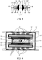
- Figures 2 to 5 show how magnetic poles, in the form of movable and/or adjustable magnetic poles, according to various embodiments of the invention are arranged in relation to the mould, water box beams arranged near the mould and a frame structure arranged around the water box beams.
- At least one static magnetic field 10 is applied, as is clear from Figure 1, to brake and split up the molten metal flowing into the mould 11 through at least one primary flow 20 and to prevent the primary flow 20 of hot molten metal, which usually contains non-metallic particles, from penetrating deep down into the non-solidified parts of the cast strand 1.
- the molten metal can be supplied to the mould 11 through a free molten metal jet but is preferably adapted to be supplied through a casting tube 12.
- the casting tube 12 is provided with an arbitrary number of outlets, directed in an arbitrary manner, and is arranged preferably centrally in the mould 11.
- the primary flow 20 of inflowing hot molten metal will in many cases become unsymmetrical.
- one or a plurality of static magnetic fields 10 are adapted to act over essentially the whole width, W, of the strand 1 formed in the mould 11. This slows down the primary flow 20 and divides it into secondary flows 21, the flow of which is controlled, and a controlled circulation of molten metal in the non-solidified portions of the strand 1 is obtained, which entails a good separation of any accompanying particles, a good control of the casting structure as well as good conditions for increased productivity.
- the intensity and propagation of the magnetic field 10 are controlled and distributed such that the maximum field strength in the mould exceeds 1000 Gauss.
- the maximum field strength in the mould should be kept within an interval of 1000 to 2000 Gauss, preferably within an interval of 1000 to 1800 Gauss.
- the field strength of the applied magnetic field 10, in a plane across the casting direction over the whole width of the cast strand 1 formed in the mould 11 and on a level with the centre of the range of action of the magnetic field, the pole centre may vary within an interval of 60 to 100 per cent of the maximum field strength without the undesired, uncontrolled secondary flows arising.
- continuous casting moulds usually comprise an inner chilled mould 11, preferably a water-cooled copper mould.
- the mould 11 is surrounded by water box beams 14, which in turn are surrounded by a frame structure 17.
- magnetic poles 15 are arranged in or near the water box beams 14 surrounding the mould 11 (see Figure 3).
- the magnetic poles 15 are arranged between the water box beams 14 and the frame structure 17 surrounding the water box beams 14 (see Figure 5).
- magnetic poles 15 are adapted to generate a static magnetic field 10 with a field strength whose intensity and propagation are controlled and distributed to act over essentially the whole width W of the strand 1 cast in the mould 11 and with a maximum magnetic field strength of at least 1000 Gauss, while at the same time the magnetic field strength on a level with the meniscus has a maximum value of 500 Gauss.
- the frame structure 17 is provided with a magnetic return path 18, shown in the figures as an iron core provided in the frame structure 17, which together with the magnetic poles 15 and the magnetic field 10 acting between the poles 15 forms a magnetic circuit for the mould 11.
- the magnetic poles 15, the magnetic field 10 and the iron core 18 may, of course, be arranged such that circuits with magnetic flux balance are obtained for each mould half or for minor parts of the mould 11.
- a construction as described above may entail considerable limitations of the possibility of inserting magnetic poles 15 in the form of both magnetic coils and permanent magnets, especially since a static magnetic field 10 covering essentially the whole width W of the cast strand 1 formed in the mould 11 is desired and where the intensity and propagation of the static magnetic field are controlled according to the invention.
- the magnetic poles 15 are arranged, in one embodiment of the invention, movable in slots in the support beams 14 of the mould (see Figure 3).
- the movable magnetic poles 15 may be arranged between the water box beams and the surrounding frame structure 17 (see Figure 5).
- the magnetic poles 15 are provided with adjustable core elements 19, in the form of both magnetic and non-magnetic sections.
- the core elements 19 are adapted to be alternately inserted/replaced to change the propagation and intensity of the magnetic field 10.
- the core 151 of the coil is provided with adjustable core elements 19 of both magnetic and non-magnetic material. In this way, the possibilities of controlling the intensity and propagation of the magnetic field 10 generated by means of the induction coil 15a are increased.
- a pole core 152 is arranged between the permanent magnet 15b and the mould 11, the pole core 152 consisting of magnetic and non-magnetic core elements 19 which are inserted/replaced to change the magnetic field 10 generated by the permanent magnet 15b.
- the use of permanent magnets 15b/induction coils 15a is, of course, not connected to the installation design in which they are exemplified but the type of magnetic pole 15 and the installation design can be replaced independently of each other.
- Figures 2 to 5 also show how, according to one embodiment of the invention, pole plates 16 are arranged adjacent to two sides of the mould 11 positioned opposite to each other.
- the pole plates 16 are adapted so as to extend along the sides of the mould 11.
- Behind the pole plates one of more magnetic poles 15 are arranged in the form of coils supplied with direct current, or permanent magnets. The fields from these magnetic poles 15 are brought together and distributed to generate and apply a static magnetic field 10 with a maximum field strength amounting to at least 1000 Gauss, suitably to between 1000 and 2000 Gauss, preferably to between 1000 and 1800 Gauss.
- a static magnetic field 10, applied, controlled and distributed according to the invention prevents molten metal from penetrating down into the cast strand 1 without being braked, while at the same time providing a control of the flow of the molten metal in non-solidified portions of the cast strand 1.
Landscapes
- Engineering & Computer Science (AREA)
- Mechanical Engineering (AREA)
- Continuous Casting (AREA)
- Moulds For Moulding Plastics Or The Like (AREA)
- Casting Or Compression Moulding Of Plastics Or The Like (AREA)
- Molds, Cores, And Manufacturing Methods Thereof (AREA)
Abstract
Description
- The invention relates to a method for casting in a mould according to the precharacterising part of
claim 1. The invention also relates to a device for carrying out said method. Such a device is known from the EP-A-0 401 504. - By this method molten liquid metal which flows into the mould is slowed down and the flow of liquid metal in the non-solidified portions of a cast strand is controlled by controlling and distributing the propagation and intensity of the magnetic field, particles accompanying the molten metal thus being separated and floating up to the surface.
- The invention is especially applicable to continuous casting in a chilled mould in which an uncontrolled inflow of hot molten metal, containing slag particles or other non-metallic particles, and/or an uncontrolled secondary flow entail problems both from the points of view of quality and production technique.
- In continuous casting, hot molten metal flows, directly or through a casting tube, into a mould. In the mould the molten metal is cooled and a solidified, self-supporting surface layer is formed before the strand, the blank, leaves the mould. If inflowing molten metal is allowed to flow into the mould in an uncontrolled manner, it will penetrate, due to its impulse, deep down into the non-solidified portions of the strand. This renders difficult the separation of particles trapped in the molten metal, which adhere to the solidification front instead of being separated to the upper surface. In addition, the self-supporting surface layer is weakened, which increases the risk of molten metal breaking through the surface layer formed in the mould.
- The Patent Abstracts of Japan Vol. 11, No. 348 & JP-A-62 130 752 describes a mould casting system with a static magnetic field generator which is positioned at a certain distance below the nozzle of a casting pipe which is submerged in the molten metal in the mould. The magnetic field generator generates a field perpendicular to the casting direction and is arranged symmetrically to the centre of the mould and extends merely over part of the width of the mould. Under operation the field generator generates a magnetic field strength of at least 1,200 Gauss at the centre of the mould. The system is suppose to prevent an increase of inclusions and to evade a breakout accident of the molten metal.
- From, for example, Swedish patent SE 436 251, it is known to arrange one or several static or periodic low-frequency magnetic fields in the path of the molten metal to brake and split up the inflowing molten metal. The magnetic fields are generated by means of magnetic poles, permanent magnets or induction coils supplied with direct current, and are arranged to act across the inflowing molten metal. The magnetic poles are arranged close to two opposite mould walls. However, the solution according to the above does not take into account any changes and unsymmetry in the flow configuration. Changes and unsymmetry in the flow configuration arise, besides in case of changed mould dimension and unsymmetrical location of the casting tubes, also by, for example, erosion and cloggings disturbing the flow out of the casting tube.
- An unsymmetrical flow configuration entails great problems with regard to quality and production engineering; for example, hot molten metal, with or without non-metallic particles, may penetrate without being braked deep down into the non-solidified parts of the strand with ensuing quality problems. The upward flows of hot molten metal towards the upper surface, the meniscus, may become too weak, resulting in a risk of the meniscus freezing. If, instead, the upward flows become too strong, wave formation arises on the upper surface as a result of the turbulence, which pulls down slag from the upper surface into the molten metal with ensuing quality problems.
- According to the invention, the flow of the molten metal in non-solidified portions of a strand is controlled in the casting of metal in which at least one strand - slab, bloom or billet - is formed in a mould which is downwardly open and which, directly or through a casting tube, is supplied with at least one primary flow of hot, inflowing molten metal, by means of at least one static or periodic, low-frequency magnetic field. The static magnetic field is generated close to the mould by means of magnetic poles, permanent magnets or coils supplied with direct current. The mentioned static magnetic field is applied to act, with a maximum magnetic field strength in the mould of at least 1000 Gauss, in the path of the inflowing molten metal to brake and split up the primary flow of molten metal flowing into the mould and thus prevent inflowing hot molten metal from penetrating deep down into the non-solidified parts, the sump, of the strand without being braked. At the same time part of the inflowing hot molten metal is controlled to flow towards the upper surface so as to obtain a desirable controlled circulation of molten metal in the non-solidified parts of the strand.
- A controlled circulation of molten metal, a separation of particles trapped in the inflowing molten metal, and a controlled heat supply to the molten metal in the upper parts of the mould, without the turbulence close to the upper surface of the molten metal, the meniscus, becoming so great that waves are formed and particles are drawn down into the molten metal, are obtained by applying a static magnetic field, according to the invention, which in the mould has a maximum magnetic field strength of at least 1000 Gauss. The static magnetic field is controlled and distributed, preferably by arranging the magnetic poles to be movable and/or providing them with adjustable core elements, to apply at least one static magnetic field to act over essentially the whole width, W, of the cast strand formed in the mould, the magnetic field strength varying within an interval of from 60 to 100 per cent of its maximum value in a plane across the casting direction, on a level with the centre of the range of action of the magnetic field while at the same time the magnetic field strength at the upper surface/the meniscus of the molten metal amounts to 500 Gauss at the most.
- When the variations in the field strength of the magnetic field are larger than those mentioned above in a plane across the casting direction, on a level with the centre of the range of action of the magnetic field, undesired secondary flows arise.
- The magnetic field is suitably controlled and distributed so that the maximum field strength in the mould amounts to between 1000 and 2000 Gauss, preferably to between 1000 and 1800 Gauss.
- To obtain a sufficient flow channel close to the meniscus and thus prevent this from freezing while at the same time the flow in these upper parts of the non-solidified portions of the cast strand does not become so strong that waves are formed on the upper surface of the molten metal, the meniscus, in the application of magnetic fields according to the invention the magnetic poles should be arranged such that the centre of the range of action of the magnetic field, its pole centre, is arranged at a distance of 300 to 600 mm below the upper surface of the molten metal, the meniscus.
- To apply the magnetic field close to the mould, a magnetic circuit is required in which the magnetic field may flow around. Such a magnetic circuit may comprise, in addition to the magnetic poles and the static magnetic field arranged between the poles, a magnetic return path, preferably in the form of an externally applied magnetic yoke. In this way the necessary magnetic flux balance is achieved for a strand or a mould. It is, of course, possible to locate the magnetic field, with associated poles and yokes, so that magnetic flux balance is obtained for each mould half or for parts of a mould. The magnetic material included in the mould may advantageously be used as magnetic return path, and therefore, in many cases, special magnetic yokes are superfluous for obtaining magnetic circuits with magnetic flux balance.
- According to a further embodiment of the invention, the distribution of the static magnetic field over essentially the whole width, W, of the strand formed in the mould is brought about by means of a pole plate arranged adjacent to a magnetic pole and a mould wall. The pole plates preferably extend along the long sides of the mould, Behind the pole plates a number of magnetic poles are arranged. Through the pole plates, magnetic fields from a plurality of magnetic poles are brought together and distributed to generate and apply a static magnetic field to act between the pole plates over essentially the whole width of the strand cast in the mould. In addition, by arranging pole plates the magnetic field is easier to adapt to variations in dimensions of the cast strand, for example the width of slabs in slabs casting.
- The magnetic poles are preferably arranged according to the invention in water box beams arranged around the mould, or in a space between the water box beams and a frame structure surrounding them.
- According to a previously described embodiment of the invention, the magnetic poles are arranged movable and/or with adjustable core elements. In this way, the propagation and intensity of the field can be controlled and distributed to ensure a good control of an incoming primary flow and secondary flows arising, in spite of the mounting limitations which exist in currently used conventional continuous casting moulds. The magnetic poles, in the form of loose coils or permanent magnets, are arranged in slots or on support beams arranged in or near the water box beams arranged around the mould.
- According to an embodiment described above, the static magnetic field can be controlled and distributed by arranging the magnetic poles with adjustable core elements.
- With magnetic poles in the form of coils supplied with direct current, this control is achieved by arranging the core of the coil with magnetic and non-magnetic sections which are inserted and replaced alternately to change the geometry of the coil core and hence the propagation and intensity of the magnetic field generated by means of the coil.
- With magnetic poles in the form of permanent magnets, the above-mentioned control is achieved by providing a pole core, arranged between the permanent magnet and the mould, with magnetic and non-magnetic sections which are inserted and replaced alternately to change the geometry of the pole core and hence the propagation and intensity of the magnetic field generated by means of the permanent magnet.
- Flow is an inert phenomenon, with a time constant of 10 seconds or more, and therefore intensity and direction of the static magnetic field can advantageously be adapted to vary in time, with a low freqency, to control the impulse of secondary flows arising.
- By the invention, the movements of the molten metal in the non-solidified parts of the cast strand are controlled. Quality improvements are obtained since the separation of non-metallic particles is improved while at the same time the structure of the solidified metal is controlled. In addition, improvements from the production point of view are obtained since the risks of remelting of the solidified surface layer or freezing of the upper surface of the molten metal are essentially eliminated, which is reflected in increased productivity in the plant as a result of improved availability and increased casting speed.
- A static magnetic field for controlling the flow in non-solidified portions of a cast strand during casting in a mould is shown in Figure 1, the magnetic field being adapted to act over essentially the whole width of a strand formed in the mould and the propagation and intensity being controlled and distributed according to the invention. Figures 2 to 5 show how magnetic poles, in the form of movable and/or adjustable magnetic poles, according to various embodiments of the invention are arranged in relation to the mould, water box beams arranged near the mould and a frame structure arranged around the water box beams.
- In continuous casting of at least one cast strand in a mould, at least one static
magnetic field 10 is applied, as is clear from Figure 1, to brake and split up the molten metal flowing into themould 11 through at least oneprimary flow 20 and to prevent theprimary flow 20 of hot molten metal, which usually contains non-metallic particles, from penetrating deep down into the non-solidified parts of thecast strand 1. The molten metal can be supplied to themould 11 through a free molten metal jet but is preferably adapted to be supplied through acasting tube 12. Thecasting tube 12 is provided with an arbitrary number of outlets, directed in an arbitrary manner, and is arranged preferably centrally in themould 11. However, for different reasons, theprimary flow 20 of inflowing hot molten metal will in many cases become unsymmetrical. According to the invention, therefore, one or a plurality of staticmagnetic fields 10 are adapted to act over essentially the whole width, W, of thestrand 1 formed in themould 11. This slows down theprimary flow 20 and divides it intosecondary flows 21, the flow of which is controlled, and a controlled circulation of molten metal in the non-solidified portions of thestrand 1 is obtained, which entails a good separation of any accompanying particles, a good control of the casting structure as well as good conditions for increased productivity. - By arranging the static
magnetic field 10, according to the invention, with the centre of its range of action, its pole centre, at a distance, H, of 300 to 600 mm below themeniscus 13, a flow channel is obtained near themeniscus 13. This flow channel ensures a sufficient heat supply to theupper surface 13 of the molten metal to prevent this from solidifying without the turbulence and the wave formation near theupper surface 13 becoming too strong with an ensuing risk of slag being drawn down into the molten metal. In addition, it is ensured that non-metallic particles are separated and float up to the slag layer positioned on theupper surface 13. - According to the invention, the intensity and propagation of the
magnetic field 10 are controlled and distributed such that the maximum field strength in the mould exceeds 1000 Gauss. Suitably, the maximum field strength in the mould should be kept within an interval of 1000 to 2000 Gauss, preferably within an interval of 1000 to 1800 Gauss. According to the invention, the field strength of the appliedmagnetic field 10, in a plane across the casting direction over the whole width of thecast strand 1 formed in themould 11 and on a level with the centre of the range of action of the magnetic field, the pole centre, may vary within an interval of 60 to 100 per cent of the maximum field strength without the undesired, uncontrolled secondary flows arising. - As will be clear from Figures 2 to 5, continuous casting moulds usually comprise an inner
chilled mould 11, preferably a water-cooled copper mould. Themould 11 is surrounded bywater box beams 14, which in turn are surrounded by aframe structure 17. To bring about a control of the flow of the molten metal in the non-solidified portions of astrand 1 cast in the continuous casting mould, according to the invention,magnetic poles 15 are arranged in or near thewater box beams 14 surrounding the mould 11 (see Figure 3). Alternatively, themagnetic poles 15 are arranged between thewater box beams 14 and theframe structure 17 surrounding the water box beams 14 (see Figure 5). According to the invention,magnetic poles 15 are adapted to generate a staticmagnetic field 10 with a field strength whose intensity and propagation are controlled and distributed to act over essentially the whole width W of thestrand 1 cast in themould 11 and with a maximum magnetic field strength of at least 1000 Gauss, while at the same time the magnetic field strength on a level with the meniscus has a maximum value of 500 Gauss. Theframe structure 17 is provided with amagnetic return path 18, shown in the figures as an iron core provided in theframe structure 17, which together with themagnetic poles 15 and themagnetic field 10 acting between thepoles 15 forms a magnetic circuit for themould 11. Themagnetic poles 15, themagnetic field 10 and theiron core 18 may, of course, be arranged such that circuits with magnetic flux balance are obtained for each mould half or for minor parts of themould 11. - A construction as described above may entail considerable limitations of the possibility of inserting
magnetic poles 15 in the form of both magnetic coils and permanent magnets, especially since a staticmagnetic field 10 covering essentially the whole width W of thecast strand 1 formed in themould 11 is desired and where the intensity and propagation of the static magnetic field are controlled according to the invention. To overcome such limitations, themagnetic poles 15 are arranged, in one embodiment of the invention, movable in slots in the support beams 14 of the mould (see Figure 3). Alternatively, the movablemagnetic poles 15 may be arranged between the water box beams and the surrounding frame structure 17 (see Figure 5). Withmagnetic poles 15 arranged movable, the intensity and propagation of the staticmagnetic field 10 can be easily changed in case of changes of the flow configuration, for example as a result of dimensional variations, preferably width variations, of the cast strand. - To further improve the possibilities of controlling and distributing the propagation and intensity of the
magnetic field 10, according to one embodiment of the invention themagnetic poles 15 are provided withadjustable core elements 19, in the form of both magnetic and non-magnetic sections. Thecore elements 19 are adapted to be alternately inserted/replaced to change the propagation and intensity of themagnetic field 10. Withmagnetic poles 15 in the form ofinduction coils 15a supplied with direct current (see Figure 3), thecore 151 of the coil is provided withadjustable core elements 19 of both magnetic and non-magnetic material. In this way, the possibilities of controlling the intensity and propagation of themagnetic field 10 generated by means of theinduction coil 15a are increased. Withmagnetic poles 15 in the form ofpermanent magnets 15b (see Figure 5), apole core 152 is arranged between thepermanent magnet 15b and themould 11, thepole core 152 consisting of magnetic andnon-magnetic core elements 19 which are inserted/replaced to change themagnetic field 10 generated by thepermanent magnet 15b. The use ofpermanent magnets 15b/induction coils 15a is, of course, not connected to the installation design in which they are exemplified but the type ofmagnetic pole 15 and the installation design can be replaced independently of each other. - Figures 2 to 5 also show how, according to one embodiment of the invention,
pole plates 16 are arranged adjacent to two sides of themould 11 positioned opposite to each other. Thepole plates 16 are adapted so as to extend along the sides of themould 11. Behind the pole plates one of moremagnetic poles 15 are arranged in the form of coils supplied with direct current, or permanent magnets. The fields from thesemagnetic poles 15 are brought together and distributed to generate and apply a staticmagnetic field 10 with a maximum field strength amounting to at least 1000 Gauss, suitably to between 1000 and 2000 Gauss, preferably to between 1000 and 1800 Gauss. - A static
magnetic field 10, applied, controlled and distributed according to the invention, prevents molten metal from penetrating down into thecast strand 1 without being braked, while at the same time providing a control of the flow of the molten metal in non-solidified portions of thecast strand 1. In addition, it is ensured that non-metallic particles contained in the inflowing molten metal are separated towards theupper surface 13, that the upper surface/themeniscus 13 is supplied with a sufficient amount of hot molten metal not to solidify, and that the turbulence and wave formation at the meniscus are essentially avoided, which eliminates the risk of casting powder/slag being drawn down from the slag layer positioned on theupper surface 13. All in all, a better yield and a higher productivity are made possible, since improved quality control in the form of improved control of the amount of inclusions and the casting structure can be combined with increased availability and higher casting speed.
Claims (14)
- A method for controlling the flow of molten metal in the non-solidified metal portions in a casting mold, wherein the mould (11) is supplied, directly or through a casting tube (12), with at least one primary flow (20) of hot inflowing molten metal and at least one cast strand (1) is formed in the mould, whereby at least one static or at low frequency alternating magnetic field (10) is generated by magnetic poles (15), consisting of permanent magnets or coils supplied with direct or at low frequency alternating current, which poles are arranged adjacent to the mould, and the magnetic field is applied to act with a maximum magnetic field strength in the mould of at least 1000 Gauss in the path of the inflowing molten metal to brake and split up the primary flow (20) of molten metal flowing into the mould and to control secondary flows (21, 22) arising, and whereby the magnetic field (10) is applied to act over essentially the whole width (W) of the cast strand (1) formed in the mould, characterized in that the magnetic field strength in the plane which extends perpendicular to the casting direction and is positioned on the level where the magnetic field strength reaches its maximum value, varies within an interval of 60 to 100 per cent of this maximum value while at the same time the field strength on a level with the upper surface/the meniscus of the molten metal has a maximum value of 500 Gauss.
- A method according to claim 1, characterized in that the magnetic field (10) is controlled and distributed to act with a maximum field strength in the mould amounting to between 1000 and 2000 Gauss.
- A method according to claim 1 or claim 2, characterized in that the magnetic field (10) is controlled and distributed to act with the centre of its range of action arranged at a distance (H) of 300 to 600 mm below the upper surface/meniscus (13) of the molten metal, to control the flow of the molten metal in non-solidified portions of the cast strand (1).
- A method according to any of the preceding claims, characterized in that the magnetic field (10) is controlled and distributed by arranging the magnetic poles (15) movable and/or with adjustable core elements (19).
- A method according to claim 4, characterized in that the intensity and propagation of the static magnetic field (10) are controlled and distributed by means of adjustable core elements (19) arranged in or adjacent to the magnetic poles (15), the core elements consisting of both magnetic and non-magnetic sections which are alternately inserted into or adjacent to the magnetic poles to control intensity and propagation of the magnetic field generated by means of the magnetic pole.
- A method according any of the preceding claims, characterized in that the magnetic field (10) is distributed to act over essentially the whole width (W) of the cast strand (1) formed in the mould by means of a pole plate (16) which is arranged near the wall of the mould (11).
- A device for controlling the flow of molten metal in the non-solidified metal portions in a casting mold, wherein the mould (11) is adapted to be supplied, directly or through a casting tube (12), with at least one primary flow (20) of hot inflowing molten metal and to form at least one cast strand (1), with magnetic poles (15), permanent magnets or coils adapted to be supplied with direct or at low frequency alternating current, being arranged adjacent to the mould, to generate at least one static or at low frequency alternating magnetic field (10) with a magnetic field strength in the mould of at least 1000 Gauss to act in the path of the inflowing molten metal and thereby to brake and split up the primary flow (20) of molten metal flowing into the mould (11) and to control secondary flows (21, 22) arising, the magnetic poles being arranged such as to distribute the magnetic field (10) to act over essentially the whole width (W) of the cast strand (1) formed in the mould, characterized in that the magnetic poles (15) are further arranged to be movable and/or are provided with adjustable core elements (19) such that the magnetic field strength in the plane which extends perpendicular to the casting direction and is positioned on the level where the magnetic field strength reaches its maximum value, varies within an interval of 60 to 100 per cent of this maximum value while at the same time the field strength on a level with the upper surface/the meniscus of the molten metal has a maximum value of 500 Gauss.
- A device according to claim 7, characterized in that the magnetic poles (15) are arranged with their pole centre at a distance (H) of 300 to 600 mm below the upper surface/meniscus (13) of the molten metal.
- A device according to claim 7 or claim 8, characterized in that the magnetic poles (15), in the form of induction coils (15a) supplied with direct current, are arranged with adjustable core elements (19) in the form of both magnetic and non-magnetic sections and that the core elements are adapted to be alternately inserted into the core (151) of the coil to change the magnetic field (10).
- A device according to claim 7 or claim 8, characterized in that said magnetic poles (15) are arranged in the form of permanent magnets (15b) and a pole core (152) arranged between the permanent magnet (15b) and the mould (11), and that the pole core is arranged with adjustable core elements (19) in the form of both magnetic and non-magnetic sections and that core elements are adapted to be alternately inserted into the pole core (152) to change the magnetic field (10).
- A device according to any of claim 7 to claim 10, characterized in that the magnetic poles (15) are arranged in the water box beams (14) of the mould.
- A device according to any of claim 7 to claim 10, characterized in that the magnetic poles (15) are arranged between the water box beams (14) of the mould and a frame structure (17) surrounding the water box beams of the mould.
- A device according to any of claim 7 to claim 12, characterized in that a magnetic return path (18) is arranged in a frame structure (17), surrounding the water box beams (14) of the mould, to constitute a magnetic circuit together with the magnetic poles (15) and the magnetic field (10) acting between the magnetic poles.
- A device according to any of claim 7 to claim 13, characterized in that a pole plate (16) is arranged near the wall of the mould (11) to distribute the static magnetic field (10) over essentially the whole width (W) of the cast strand (1) formed in the mould.
Applications Claiming Priority (3)
| Application Number | Priority Date | Filing Date | Title |
|---|---|---|---|
| SE9100184 | 1991-01-21 | ||
| SE9100184A SE500745C2 (en) | 1991-01-21 | 1991-01-21 | Methods and apparatus for casting in mold |
| PCT/SE1992/000025 WO1992012814A1 (en) | 1991-01-21 | 1992-01-16 | A method and a device for casting in a mould |
Publications (2)
| Publication Number | Publication Date |
|---|---|
| EP0568579A1 EP0568579A1 (en) | 1993-11-10 |
| EP0568579B1 true EP0568579B1 (en) | 1997-04-23 |
Family
ID=20381675
Family Applications (1)
| Application Number | Title | Priority Date | Filing Date |
|---|---|---|---|
| EP92903418A Expired - Lifetime EP0568579B1 (en) | 1991-01-21 | 1992-01-16 | A method and a device for casting in a mould |
Country Status (8)
| Country | Link |
|---|---|
| US (1) | US5404933A (en) |
| EP (1) | EP0568579B1 (en) |
| JP (1) | JPH06504726A (en) |
| AT (1) | ATE152018T1 (en) |
| DE (1) | DE69219317T2 (en) |
| ES (1) | ES2103362T3 (en) |
| SE (1) | SE500745C2 (en) |
| WO (1) | WO1992012814A1 (en) |
Families Citing this family (17)
| Publication number | Priority date | Publication date | Assignee | Title |
|---|---|---|---|---|
| SE501322C2 (en) * | 1993-01-19 | 1995-01-16 | Asea Brown Boveri | Device for injection molding in mold |
| AT404104B (en) * | 1994-07-01 | 1998-08-25 | Voest Alpine Ind Anlagen | CONTINUOUS CHOCOLATE WITH A STIRRIER INCLUDING A MAGNETIC CIRCLE |
| DE4429685A1 (en) * | 1994-08-22 | 1996-02-29 | Schloemann Siemag Ag | Continuous caster for casting thin slabs |
| SE509112C2 (en) * | 1997-04-18 | 1998-12-07 | Asea Brown Boveri | Device for continuous casting of two blanks in parallel |
| CA2242037C (en) * | 1997-07-01 | 2004-01-27 | Ipsco Inc. | Controllable variable magnetic field apparatus for flow control of molten steel in a casting mold |
| US6341642B1 (en) | 1997-07-01 | 2002-01-29 | Ipsco Enterprises Inc. | Controllable variable magnetic field apparatus for flow control of molten steel in a casting mold |
| FR2772294B1 (en) * | 1997-12-17 | 2000-03-03 | Rotelec Sa | ELECTROMAGNETIC BRAKING EQUIPMENT OF A MOLTEN METAL IN A CONTINUOUS CASTING SYSTEM |
| KR100376504B1 (en) | 1998-08-04 | 2004-12-14 | 주식회사 포스코 | Continuous casting method and continuous casting apparatus used |
| US6929055B2 (en) | 2000-02-29 | 2005-08-16 | Rotelec | Equipment for supplying molten metal to a continuous casting ingot mould |
| FR2805483B1 (en) * | 2000-02-29 | 2002-05-24 | Rotelec Sa | EQUIPMENT FOR SUPPLYING MOLTEN METAL TO A CONTINUOUS CASTING LINGOTIERE, AND METHOD OF USING SAME |
| KR20020051088A (en) * | 2000-12-22 | 2002-06-28 | 이구택 | Molten metal supply method and equipment for continuous casting |
| RU2216427C1 (en) * | 2002-04-24 | 2003-11-20 | Открытое акционерное общество "АВИСМА титано-магниевый комбинат" | Method for casting metallic ingots and apparatus for performing the same |
| ES2287797T3 (en) * | 2003-12-18 | 2007-12-16 | Sms Demag Aktiengesellschaft | MAGNETIC BRAKE FOR CONTINUOUS COLADA COQUILLLA. |
| DE102004046729A1 (en) * | 2003-12-18 | 2005-07-14 | Sms Demag Ag | Continuous casting mold, especially a thin slab mold, used in the continuous casting of metals comprises permanent magnets which give a varying filed strength using differing magnet strengths over the width and/or height |
| US7984749B2 (en) * | 2003-12-18 | 2011-07-26 | Sms Siemag Ag | Magnetic device for continuous casting mold |
| CN103331435A (en) * | 2013-07-03 | 2013-10-02 | 上海大学 | Method for controlling metal solidification phase texture in combined mode through external rotating magnetic field and current and fusion casting device of method |
| KR102310701B1 (en) * | 2019-12-27 | 2021-10-08 | 주식회사 포스코 | Casting apparatus and casting method |
Family Cites Families (5)
| Publication number | Priority date | Publication date | Assignee | Title |
|---|---|---|---|---|
| JPS5855157A (en) * | 1981-09-28 | 1983-04-01 | Sumitomo Metal Ind Ltd | Method and device for controlling charged flow in continuous casting |
| KR930002836B1 (en) * | 1989-04-27 | 1993-04-10 | 가와사끼 세이데쓰 가부시까가이샤 | Continuous casting method of steel using static magnetic field |
| JP2726096B2 (en) * | 1989-04-27 | 1998-03-11 | 川崎製鉄株式会社 | Continuous casting method of steel using static magnetic field |
| WO1991012909A1 (en) * | 1990-02-23 | 1991-09-05 | Nippon Steel Corporation | Continuous casting apparatus |
| US5033534A (en) * | 1990-03-02 | 1991-07-23 | Nkk Corporation | Method for continuous casting of steel |
-
1991
- 1991-01-21 SE SE9100184A patent/SE500745C2/en unknown
-
1992
- 1992-01-16 US US08/087,701 patent/US5404933A/en not_active Expired - Lifetime
- 1992-01-16 DE DE69219317T patent/DE69219317T2/en not_active Expired - Lifetime
- 1992-01-16 EP EP92903418A patent/EP0568579B1/en not_active Expired - Lifetime
- 1992-01-16 ES ES92903418T patent/ES2103362T3/en not_active Expired - Lifetime
- 1992-01-16 JP JP4503316A patent/JPH06504726A/en active Pending
- 1992-01-16 WO PCT/SE1992/000025 patent/WO1992012814A1/en not_active Ceased
- 1992-01-16 AT AT92903418T patent/ATE152018T1/en not_active IP Right Cessation
Non-Patent Citations (1)
| Title |
|---|
| publ 1987-06-13 (KAWASAKI STEEL CORP). * |
Also Published As
| Publication number | Publication date |
|---|---|
| JPH06504726A (en) | 1994-06-02 |
| SE9100184L (en) | 1992-07-22 |
| EP0568579A1 (en) | 1993-11-10 |
| WO1992012814A1 (en) | 1992-08-06 |
| ES2103362T3 (en) | 1997-09-16 |
| SE9100184D0 (en) | 1991-01-21 |
| ATE152018T1 (en) | 1997-05-15 |
| DE69219317D1 (en) | 1997-05-28 |
| SE500745C2 (en) | 1994-08-22 |
| DE69219317T2 (en) | 1997-11-20 |
| US5404933A (en) | 1995-04-11 |
Similar Documents
| Publication | Publication Date | Title |
|---|---|---|
| US5404933A (en) | Method and a device for casting in a mould | |
| US6253832B1 (en) | Device for casting in a mould | |
| SE436251B (en) | SET AND DEVICE FOR MOVING THE NON-STANDED PARTS OF A CASTING STRING | |
| JP3725028B2 (en) | Electromagnetic braking device for molten metal in continuous casting molds. | |
| EP2682201A1 (en) | Method and apparatus for the continuous casting of aluminium alloys | |
| AU778670B2 (en) | Method for vertical continuous casting of metals using electromagnetic fields and casting installation therefor | |
| CA2074866A1 (en) | Process for ingot casting employing a magnetic field for reducing macrosegregation and associated apparatus and ingot | |
| US4986340A (en) | Method for stirring and/or braking of melts and a device for carrying out this method | |
| WO1996026029A1 (en) | A method and a device for casting in a mould | |
| US5613548A (en) | Continuous casting plant for casting thin slabs | |
| EP0873212B1 (en) | Method and device for casting of metal | |
| US4562879A (en) | Electromagnetically stirring the melt in a continuous-casting mold | |
| US6843305B2 (en) | Method and device for controlling stirring in a strand | |
| US6332493B1 (en) | Device for continuous casting of two strands in parallel | |
| EP0797487B1 (en) | Method for casting in a mould | |
| US6006822A (en) | Controllable variable magnetic field apparatus for flow control of molten steel in a casting mold | |
| WO1999011404A1 (en) | Method and device for continuous or semi-continuous casting of metal | |
| JPH04319052A (en) | Method and apparatus for controlling flow of molten steel in mold | |
| WO1995013154A1 (en) | Method and device for braking the movement of a melt during casting in a mould | |
| JPH04274845A (en) | Continuous casting method for multilayer cast billet and casting mold | |
| DE3369258D1 (en) | Method of electromagnetically stirring molten steel in continuous casting |
Legal Events
| Date | Code | Title | Description |
|---|---|---|---|
| PUAI | Public reference made under article 153(3) epc to a published international application that has entered the european phase |
Free format text: ORIGINAL CODE: 0009012 |
|
| 17P | Request for examination filed |
Effective date: 19930705 |
|
| AK | Designated contracting states |
Kind code of ref document: A1 Designated state(s): AT BE DE ES FR GB IT LU NL |
|
| 17Q | First examination report despatched |
Effective date: 19950707 |
|
| GRAG | Despatch of communication of intention to grant |
Free format text: ORIGINAL CODE: EPIDOS AGRA |
|
| GRAH | Despatch of communication of intention to grant a patent |
Free format text: ORIGINAL CODE: EPIDOS IGRA |
|
| GRAH | Despatch of communication of intention to grant a patent |
Free format text: ORIGINAL CODE: EPIDOS IGRA |
|
| GRAH | Despatch of communication of intention to grant a patent |
Free format text: ORIGINAL CODE: EPIDOS IGRA |
|
| GRAH | Despatch of communication of intention to grant a patent |
Free format text: ORIGINAL CODE: EPIDOS IGRA |
|
| GRAA | (expected) grant |
Free format text: ORIGINAL CODE: 0009210 |
|
| AK | Designated contracting states |
Kind code of ref document: B1 Designated state(s): AT BE DE ES FR GB IT LU NL |
|
| REF | Corresponds to: |
Ref document number: 152018 Country of ref document: AT Date of ref document: 19970515 Kind code of ref document: T |
|
| REF | Corresponds to: |
Ref document number: 69219317 Country of ref document: DE Date of ref document: 19970528 |
|
| ET | Fr: translation filed | ||
| REG | Reference to a national code |
Ref country code: ES Ref legal event code: FG2A Ref document number: 2103362 Country of ref document: ES Kind code of ref document: T3 |
|
| PLBE | No opposition filed within time limit |
Free format text: ORIGINAL CODE: 0009261 |
|
| STAA | Information on the status of an ep patent application or granted ep patent |
Free format text: STATUS: NO OPPOSITION FILED WITHIN TIME LIMIT |
|
| 26N | No opposition filed | ||
| PGFP | Annual fee paid to national office [announced via postgrant information from national office to epo] |
Ref country code: LU Payment date: 20010109 Year of fee payment: 10 |
|
| PGFP | Annual fee paid to national office [announced via postgrant information from national office to epo] |
Ref country code: BE Payment date: 20010314 Year of fee payment: 10 |
|
| REG | Reference to a national code |
Ref country code: GB Ref legal event code: IF02 |
|
| PG25 | Lapsed in a contracting state [announced via postgrant information from national office to epo] |
Ref country code: LU Free format text: LAPSE BECAUSE OF NON-PAYMENT OF DUE FEES Effective date: 20020116 |
|
| PG25 | Lapsed in a contracting state [announced via postgrant information from national office to epo] |
Ref country code: BE Free format text: LAPSE BECAUSE OF NON-PAYMENT OF DUE FEES Effective date: 20020131 |
|
| BERE | Be: lapsed |
Owner name: ASEA BROWN BOVERI A.B. Effective date: 20020131 |
|
| PGFP | Annual fee paid to national office [announced via postgrant information from national office to epo] |
Ref country code: IT Payment date: 20110120 Year of fee payment: 20 Ref country code: NL Payment date: 20110117 Year of fee payment: 20 Ref country code: FR Payment date: 20110128 Year of fee payment: 20 Ref country code: AT Payment date: 20101222 Year of fee payment: 20 Ref country code: DE Payment date: 20110112 Year of fee payment: 20 |
|
| PGFP | Annual fee paid to national office [announced via postgrant information from national office to epo] |
Ref country code: ES Payment date: 20110216 Year of fee payment: 20 Ref country code: GB Payment date: 20110112 Year of fee payment: 20 |
|
| REG | Reference to a national code |
Ref country code: DE Ref legal event code: R071 Ref document number: 69219317 Country of ref document: DE |
|
| REG | Reference to a national code |
Ref country code: DE Ref legal event code: R071 Ref document number: 69219317 Country of ref document: DE |
|
| REG | Reference to a national code |
Ref country code: NL Ref legal event code: V4 Effective date: 20120116 |
|
| REG | Reference to a national code |
Ref country code: GB Ref legal event code: PE20 Expiry date: 20120115 |
|
| REG | Reference to a national code |
Ref country code: ES Ref legal event code: FD2A Effective date: 20120411 |
|
| REG | Reference to a national code |
Ref country code: AT Ref legal event code: MK07 Ref document number: 152018 Country of ref document: AT Kind code of ref document: T Effective date: 20120116 |
|
| PG25 | Lapsed in a contracting state [announced via postgrant information from national office to epo] |
Ref country code: ES Free format text: LAPSE BECAUSE OF EXPIRATION OF PROTECTION Effective date: 20120117 Ref country code: DE Free format text: LAPSE BECAUSE OF EXPIRATION OF PROTECTION Effective date: 20120117 |
|
| PG25 | Lapsed in a contracting state [announced via postgrant information from national office to epo] |
Ref country code: GB Free format text: LAPSE BECAUSE OF EXPIRATION OF PROTECTION Effective date: 20120115 |