EP0568559B1 - Device for handling vehicle wheel - Google Patents
Device for handling vehicle wheel Download PDFInfo
- Publication number
- EP0568559B1 EP0568559B1 EP92902768A EP92902768A EP0568559B1 EP 0568559 B1 EP0568559 B1 EP 0568559B1 EP 92902768 A EP92902768 A EP 92902768A EP 92902768 A EP92902768 A EP 92902768A EP 0568559 B1 EP0568559 B1 EP 0568559B1
- Authority
- EP
- European Patent Office
- Prior art keywords
- wheel
- support members
- support member
- disc wheel
- vehicle
- Prior art date
- Legal status (The legal status is an assumption and is not a legal conclusion. Google has not performed a legal analysis and makes no representation as to the accuracy of the status listed.)
- Expired - Lifetime
Links
- 230000000284 resting effect Effects 0.000 description 2
- 238000005452 bending Methods 0.000 description 1
- 238000012423 maintenance Methods 0.000 description 1
- 238000009423 ventilation Methods 0.000 description 1
Images


Classifications
-
- B—PERFORMING OPERATIONS; TRANSPORTING
- B60—VEHICLES IN GENERAL
- B60B—VEHICLE WHEELS; CASTORS; AXLES FOR WHEELS OR CASTORS; INCREASING WHEEL ADHESION
- B60B30/00—Means for holding wheels or parts thereof
- B60B30/06—Means for holding wheels or parts thereof engaging the wheel body, e.g. the rim
-
- B—PERFORMING OPERATIONS; TRANSPORTING
- B60—VEHICLES IN GENERAL
- B60B—VEHICLE WHEELS; CASTORS; AXLES FOR WHEELS OR CASTORS; INCREASING WHEEL ADHESION
- B60B29/00—Apparatus or tools for mounting or dismounting wheels
- B60B29/002—Apparatus or tools for mounting or dismounting wheels provided with a dolly
-
- B—PERFORMING OPERATIONS; TRANSPORTING
- B60—VEHICLES IN GENERAL
- B60B—VEHICLE WHEELS; CASTORS; AXLES FOR WHEELS OR CASTORS; INCREASING WHEEL ADHESION
- B60B30/00—Means for holding wheels or parts thereof
- B60B30/10—Means for holding wheels or parts thereof characterised by being provided on a dolly
-
- B—PERFORMING OPERATIONS; TRANSPORTING
- B66—HOISTING; LIFTING; HAULING
- B66F—HOISTING, LIFTING, HAULING OR PUSHING, NOT OTHERWISE PROVIDED FOR, e.g. DEVICES WHICH APPLY A LIFTING OR PUSHING FORCE DIRECTLY TO THE SURFACE OF A LOAD
- B66F5/00—Mobile jacks of the garage type mounted on wheels or rollers
- B66F5/04—Mobile jacks of the garage type mounted on wheels or rollers with fluid-pressure-operated lifting gear
-
- B—PERFORMING OPERATIONS; TRANSPORTING
- B60—VEHICLES IN GENERAL
- B60B—VEHICLE WHEELS; CASTORS; AXLES FOR WHEELS OR CASTORS; INCREASING WHEEL ADHESION
- B60B2340/00—Wheel transporting, Mounting of wheels
- B60B2340/10—Operation mode
- B60B2340/12—Operated manually
-
- B—PERFORMING OPERATIONS; TRANSPORTING
- B60—VEHICLES IN GENERAL
- B60B—VEHICLE WHEELS; CASTORS; AXLES FOR WHEELS OR CASTORS; INCREASING WHEEL ADHESION
- B60B2340/00—Wheel transporting, Mounting of wheels
- B60B2340/30—Wheel transporting or handling devices
- B60B2340/32—Wheel transporting or handling devices for gripping the wheel
-
- B—PERFORMING OPERATIONS; TRANSPORTING
- B60—VEHICLES IN GENERAL
- B60B—VEHICLE WHEELS; CASTORS; AXLES FOR WHEELS OR CASTORS; INCREASING WHEEL ADHESION
- B60B2340/00—Wheel transporting, Mounting of wheels
- B60B2340/30—Wheel transporting or handling devices
- B60B2340/36—Wheel transporting or handling devices the devices being provided on a dolly
-
- B—PERFORMING OPERATIONS; TRANSPORTING
- B60—VEHICLES IN GENERAL
- B60B—VEHICLE WHEELS; CASTORS; AXLES FOR WHEELS OR CASTORS; INCREASING WHEEL ADHESION
- B60B2900/00—Purpose of invention
- B60B2900/10—Reduction of
- B60B2900/116—Product variety, e.g. by standardisation or use of adapters
-
- B—PERFORMING OPERATIONS; TRANSPORTING
- B60—VEHICLES IN GENERAL
- B60Y—INDEXING SCHEME RELATING TO ASPECTS CROSS-CUTTING VEHICLE TECHNOLOGY
- B60Y2200/00—Type of vehicle
- B60Y2200/10—Road Vehicles
- B60Y2200/14—Trucks; Load vehicles, Busses
-
- Y—GENERAL TAGGING OF NEW TECHNOLOGICAL DEVELOPMENTS; GENERAL TAGGING OF CROSS-SECTIONAL TECHNOLOGIES SPANNING OVER SEVERAL SECTIONS OF THE IPC; TECHNICAL SUBJECTS COVERED BY FORMER USPC CROSS-REFERENCE ART COLLECTIONS [XRACs] AND DIGESTS
- Y10—TECHNICAL SUBJECTS COVERED BY FORMER USPC
- Y10T—TECHNICAL SUBJECTS COVERED BY FORMER US CLASSIFICATION
- Y10T29/00—Metal working
- Y10T29/53—Means to assemble or disassemble
- Y10T29/53909—Means comprising hand manipulatable tool
- Y10T29/53913—Aligner or center
- Y10T29/53922—Auto wheel with auto chassis
Definitions
- the invention relates to a device for handling a vehicle wheel, especially for removing a wheel of a lorry from or installing it on an axle. More particularly, the invention relates to a device for handling a disc wheel of a vehicle according to the preamble of claim 1.
- the device of the invention is used when a vehicle wheel has to be removed from the axle or shaft for repair or maintenance, for instance, or when the wheel has to be removed from the shaft to replace a worn tyre with a new one, or when a spare wheel has to be installed on the road due to tyre failure.
- the weight of a vehicle wheel itself is so great that it may be dangerous to handle it merely by human power. Therefore auxiliary means are required for changing the wheel.
- Labour legislation requires that the specified lifting weights should not be exceeded.
- the handling of the vehicle wheel requires accuracy, as the disc wheel is installed tightly on the shaft of the vehicle, and it is important that the vehicle wheel can be handled easily so that the wheel loading the vehicle shaft can be shifted, that is, in practice, rotated accurately.
- the change of the vehicle wheel is especially difficult when the spare tyre has to be installed in the vehicle in field conditions, because the driver nowadays has to face the problem alone and the conditions are difficult.
- the prior art has many disadvantages.
- the handling of the vehicle wheel is very difficult by means of the existing devices.
- a damaged vehicle tyre e.g. a tyre broken completely apart, in which most of the tyre portion of rubber has disappeared, cannot be gripped appropriately by the prior devices.
- a further disadvantage of certain other known solutions is that the structure of the device is such that it comprises various means positioned close to the end of the shaft positioned in the middle of the disc wheel, and so the inner wheel of twin wheels cannot, for instance, be removed by the prior art devices, because the parts of the device come into contact with the shaft end when one attempts to push the device towards the inner wheel of the twin wheels.
- EP - A - 0 052 586 describes a device according to the preamble of claim 1 for fitting and removing large vehicle wheels, comprising a vertical frame portion and one support member connected to said frame portion and arranged to be fitted into a disc wheel groove such that the wheel is rotatable on the support member.
- US-A-4 022 341 discloses a device for lifting a vehicle wheel from a shaft.
- the wheel is handled with this device by the disc wheel groove, but the support means to be fitted into the disc wheel groove is such in shape that the wheel can only be lifted by means of it, as the support means comprises two adjacent narrow plate portions on which the wheel cannot be rotated.
- lifting in this device is carried out from the upper edge of the device by means of a lifting hook and a wire rope.
- An object of the present invention is to provide a device for handling a vehicle wheel, which avoids the problems and disadvantages of the prior art solutions and enables the vehicle wheel to be removed and/or installed and handled efficiently and easily.
- the solution of the invention enables the vehicle wheel to be rotated on support members fitted into the disc wheel groove, so that it is also possible readily to align the bolt holes of the wheel.
- the present invention consists in a device for handling a disc wheel of a vehicle, having the characterising features of claim 1.
- Various tasks involving handling of a vehicle wheel can be carried out easily by means of the device of the invention.
- the structure of the device enables the wheel to be rotated and, accordingly, the bolt holes of a disc wheel, for instance, to be aligned.
- the inner wheel of twin wheels can be handled easily by the device according to the invention.
- the device of the invention comprises a frame, that is, frame portions 1 and 2 which are movable with respect to each other either by means of an external lifting means or a lifting means 3 comprised in the device.
- the figures show the lifting means 3, such as a hydraulic lifter, having a fixed portion 4 supported on a transverse rod 5 connected to the inner frame portion 1, that is, to the stationary frame portion 1 of the device, and a movable portion 6 supporting a rod 5a interconnecting the two halves of the outer frame portion 2 of the device, the outer frame portion being movable upward with respect to the stationary inner frame portion 1 by said rod 5a under the influence of a force exerted on the lifting means 3 by a crank 7.
- the lifting means 3 may also be supported on an underlying surface.
- the stationary inner frame portion 1 of the device is connected to support wheels 8, of which there are several and by means of which the device is easy to displace on the underlying surface 9.
- the inner frame portion 1 of the device is positioned at least partly within the outer frame portion 2 on two sides so that the device comprises a structure formed by connecting the inner frame tubes 1 with the transverse rod 5 and a structure which comprises the outer frame tubes 2 and an interconnecting upper transverse tube 10 and the rod 5a, on which a lifting force can be exerted by the lifting means 3.
- Both halves of the outer frame tube 2 and the upper transverse tube 10 are preferably made of the same tube by bending.
- the device comprises at least three gripping means 11, 12, 13, by means of which a vehicle wheel 14 can be lifted or otherwise displaced or supported when a tyre 15 with its disc wheel 16 is removed or installed.
- the gripping means 11, 12, 13 comprises arms 17, 18, 19 or other similar means, which are connected to the frame portion 2 liftable by the lifting means 3, and preferably, roller-like support members 21, 22, 23 connected to the arms 17, 18, 19, respectively. These support members are arranged to be fitted into a disc wheel groove 20 at the lifting stage, and form part of the gripping means 11, 12, 13 as do the support arms.
- the term gripping means refers to an entity comprising the support member, such as a roller-like or ball-like support member, and its fastening structure, such as an arm.
- each support member is connected by a fastening mechanism, such as the arm 17, 18, 19, to the outer frame tube 2 of the frame, that is, to the vertically movable portion of the frame structure of the device, so that when the outer frame portion 2 is lifted by the lifting means 3, the gripping means 11, 12, 13 with their support members 21, 22, 23 rise with the outer frame portion 2, which can be moved from below in the vertical direction, and so the support members are fitted into the disc wheel groove 20.
- the wheel 14 remains resting on the support members 21-23 so that the wheel no longer loads the shaft of the vehicle.
- the support member arms 17, 18, 19 comprised in the gripping means 11, 12, 13 are so shaped and dimensioned that two or more roll-like support members 21, 22, 23 can be fitted into the disc wheel groove 20 at the lifting stage, so that the support members 21, 22, 23 are positioned in the disc wheel groove 20, and when the lifting movement is continued, the vehicle wheel 14 rises whilst resting on the gripping means 11, 12, 13, that is, on the support members 21, 22, 23, in practice.
- By adjusting the lifting means 3 it is thus possible to find a lifting height at which the wheel loads the vehicle shaft 24 as little as possible after the fastening bolts of the disc wheel 16 have been removed.
- the vehicle wheel 14 can be rotated easily, which is important for the performance of the work, especially for the alignment of bolt holes 25 in the disc wheel 16.
- the reference numeral 30 indicates ventilation openings in the disc wheel 16.
- Figure 5 shows the mechanism of the gripping means 11, 12 or 13 to be fitted into the disc wheel groove, which mechanism enables the roller-like support member 21, 22 or 23 and the support member arm 17, 18, or 19 to be displaced and tightened against the disc wheel groove 20.
- the mechanism comprises e.g. a gear rack mechanism 31, 32, 33, 34, so that the arm 17, 18, 19 attached to the support member 21, 22 or 23 has a gear rack 31, which can be moved in a housing 32 by means of a gear 33 and a crank handle 34. If required, the disc wheel 16 can be locked by means of the disc wheel groove 20.
- the support members 21, 22, 23 are positioned in the device so that an end 36 of the vehicle shaft 24 carrying the vehicle wheel 14 to be removed or installed is accessible through an opening in the structure of the device. In this way, it is also possible to handle and rotate twin wheels, as the end of the shaft of the vehicle does not make contact with the device.
- a larger wheel is handled on the left side as compared with the right side. It is apparent from the figure that it has to be possible to fasten the support members higher when handling large wheels.
- the support members 21 and 23 above a horizontal centre line F of the wheel are connected to height adjusting means of the support members.
- the height adjusting means is a slide means 40 for the support member 21 and another slide means 41 for the support member 23.
- the first slide means 40 can be moved obliquely upward and downward in the direction shown by the arrow A.
- the second slide means 41 can be moved obliquely upward and downward in the direction of the arrow B.
- the slide means is shown in Figure 8, in which the slide means 40 and 41 comprises an opening 70 for a shaft means 51 and 53, respectively, and an opening 71 shown by broken lines G for a locking means 72 shown in Figure 4.
- the slide means 40 comprises an opening 73 for the upper transverse rod 10 carrying the support members.
- Figure 6 shows the other structural parts shown in Figure 6 mainly correspond to those shown in Figure 1; as shown in Figure 6, the slide means 40 and 41 are attached to the vertically movable frame portion 2 of the frame, which can be lifted by the lifting means 3.
- Figure 6 also shows the preferred embodiment shown in Figures 4 and 7, in which at least one support member is connected to a turning means 43 biassed by a spring member 42, so that the support member 22 can be lifted by the action of the movement of the turning means 43 away from the disc wheel groove 20 and returned into the disc wheel groove 20 by the action of the spring force of the spring member.
- This arrangement also facilitates the handling of larger wheels while it also locks, if required, the wheel in position if the spring force is sufficient.
- arcs C and D show the path of the support member 22, moveable by the turning means 43, when the support member 22 is lifted from the disc wheel groove 20 by the turning means 43.
- the shaft of the turning means is indicated with the reference numeral 44.
- Figure 7 is taken in the same direction as Figures 2 and 4.
- Bolt holes 25 extend through a disc wheel end 54 shown in the middle of Figure 7.
- one or more support members 22 to be fitted into the disc wheel groove 20 are connected to a support member collar portion 45, the edge of the disc wheel groove 20 being arranged to be fitted between the support member 22 and the collar portion 45.
- the spring-loaded support member 22 is the support member which is connected to the collar portion 45.
- the support members 21 and 23 are attached by means of shafts 51 and 53 to the vertically movable frame portion 2 or to the upper transverse tube 10 interconnecting the halves of the frame portion 2.
- At least one support member 21, 23 is connected to a handle means 61, 63, positioned on the shaft 51, 53 of the support member, respectively, the support member 21, 23 being rotatable by the handle means 61, 63, as shown in Figure 7 (also Figures 3 and 4).
- Figure 7 also shows the slide means 40 with the opening 73, through which the upper transverse tube 10 extends.
- the device comprises at least two support members 21, 23 which are fitted into the disc wheel groove 20 above a horizontal centre line F of the wheel on opposite sides of a vertical centre line E of the wheel, and at least one support member 22 which is fitted into the disc wheel groove 20 below the horizontal centre line F, as shown in Figure 6.
- This arrangement enables the wheel to be rotated easily and ensures that the wheel stays in place in the device.
- FIG 3 is a top view of the device.
- the figure shows the outer, vertically movable frame portion 2, which comprises two tubes and an interconnecting transverse tube indicated by the reference numeral 10 similarly as in Figure 1.
- the outer, vertically movable frame portion 2 can be lifted with respect to the stationary inner frame portion 1 by the lifting means 3 from the lower interconnecting rod 5a, which, however, is not shown in Figure 3, as it remains below the upper transverse tube 10.
- the shafts 51 and 53 pass through tubes 81 and 83.
- the shaft 51 for example, is mounted to the tube 81 by a bearing 91.
- the tube 81 and 83 are attached to the upper transverse tube 10 of the vertically movable frame portion 2; in the preferred embodiment of the invention, the support members 21 and 23 are thus attached rotatably to the tubes 81 and 83 by means of the shafts 51 and 53, and so the wheel can be rotated accurately by means of the handle means 61 and 63 connected to the shafts 51 and 53.
- the tubes 81 and 83 act as fastening means for the support members 21 and 23.
- the fastening means that is, the tubes 81 and 83, can be attached directly to the frame portion 2 or the attachment can be made indirectly by attaching the tubes 81 and 82 to the upper transverse tube 10 interconnecting the different halves of the frame portion 2, as shown in Figures 3, 4 and 7.
- the device according to the invention is suitable for handling vehicle wheels.
- the device according to the invention can be used for handling tractor, implement, airplane, car or van wheels, for instance.
Landscapes
- Engineering & Computer Science (AREA)
- Mechanical Engineering (AREA)
- Life Sciences & Earth Sciences (AREA)
- Geology (AREA)
- Structural Engineering (AREA)
- Handcart (AREA)
- Vehicle Cleaning, Maintenance, Repair, Refitting, And Outriggers (AREA)
- Chain Conveyers (AREA)
- Testing Of Balance (AREA)
- Steroid Compounds (AREA)
- Load-Engaging Elements For Cranes (AREA)
- Forklifts And Lifting Vehicles (AREA)
- Automobile Manufacture Line, Endless Track Vehicle, Trailer (AREA)
- Vehicle Body Suspensions (AREA)
- Auxiliary Drives, Propulsion Controls, And Safety Devices (AREA)
Abstract
Description
- The invention relates to a device for handling a vehicle wheel, especially for removing a wheel of a lorry from or installing it on an axle. More particularly, the invention relates to a device for handling a disc wheel of a vehicle according to the preamble of
claim 1. - The device of the invention is used when a vehicle wheel has to be removed from the axle or shaft for repair or maintenance, for instance, or when the wheel has to be removed from the shaft to replace a worn tyre with a new one, or when a spare wheel has to be installed on the road due to tyre failure.
- The weight of a vehicle wheel itself is so great that it may be dangerous to handle it merely by human power. Therefore auxiliary means are required for changing the wheel. Labour legislation requires that the specified lifting weights should not be exceeded. In addition, the handling of the vehicle wheel requires accuracy, as the disc wheel is installed tightly on the shaft of the vehicle, and it is important that the vehicle wheel can be handled easily so that the wheel loading the vehicle shaft can be shifted, that is, in practice, rotated accurately. The change of the vehicle wheel is especially difficult when the spare tyre has to be installed in the vehicle in field conditions, because the driver nowadays has to face the problem alone and the conditions are difficult.
- It is previously known to carry out the change of a worn or e.g. damaged wheel of a vehicle, such as a heavy lorry, by using auxiliary means. Solutions known from the prior art comprise long rollers to be positioned under or on both sides of the tyre, and the vehicle wheel is then lifted by moving the rollers. Such a structure is disclosed e.g. in the publications DE-A-3 047 844; US-A-4 690 605; and EP-A-0 125 551. EP-A-0 114 147 discloses a structure comprising a means by which the wheel can be locked in position by pressing said means against the disc wheel.
- The prior art has many disadvantages. When the tyre of the vehicle wheel is damaged, e.g. blown out, the handling of the vehicle wheel is very difficult by means of the existing devices. A damaged vehicle tyre, e.g. a tyre broken completely apart, in which most of the tyre portion of rubber has disappeared, cannot be gripped appropriately by the prior devices.
- A further disadvantage of certain other known solutions is that the structure of the device is such that it comprises various means positioned close to the end of the shaft positioned in the middle of the disc wheel, and so the inner wheel of twin wheels cannot, for instance, be removed by the prior art devices, because the parts of the device come into contact with the shaft end when one attempts to push the device towards the inner wheel of the twin wheels.
- EP - A - 0 052 586 describes a device according to the preamble of
claim 1 for fitting and removing large vehicle wheels, comprising a vertical frame portion and one support member connected to said frame portion and arranged to be fitted into a disc wheel groove such that the wheel is rotatable on the support member. - US-A-4 022 341 discloses a device for lifting a vehicle wheel from a shaft. The wheel is handled with this device by the disc wheel groove, but the support means to be fitted into the disc wheel groove is such in shape that the wheel can only be lifted by means of it, as the support means comprises two adjacent narrow plate portions on which the wheel cannot be rotated. In addition, lifting in this device is carried out from the upper edge of the device by means of a lifting hook and a wire rope.
- An object of the present invention is to provide a device for handling a vehicle wheel, which avoids the problems and disadvantages of the prior art solutions and enables the vehicle wheel to be removed and/or installed and handled efficiently and easily. The solution of the invention enables the vehicle wheel to be rotated on support members fitted into the disc wheel groove, so that it is also possible readily to align the bolt holes of the wheel.
- Accordingly the present invention consists in a device for handling a disc wheel of a vehicle, having the characterising features of
claim 1. - Various tasks involving handling of a vehicle wheel can be carried out easily by means of the device of the invention. The structure of the device enables the wheel to be rotated and, accordingly, the bolt holes of a disc wheel, for instance, to be aligned. In addition, the inner wheel of twin wheels can be handled easily by the device according to the invention.
- The invention will be described by way of example with reference to the attached drawings, in which:-
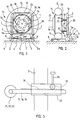
- Figure 1 shows the device of the invention as seen in the direction of the shaft of a vehicle;
- Figure 2 shows the device of the invention as seen in a direction perpendicular to the shaft of the vehicle;
- Figure 3 is a top view of the device of the invention;
- Figure 4 is a side view of the device shown in Figure 3;
- Figure 5 shows a displacing mechanism for a support member of a gripping means to be fitted into the disc wheel groove of a disc wheel;
- Figure 6 shows the device of the invention in the direction of Figure 1;
- Figure 7 shows a fastening mechanism for the support members;
- Figure 8 shows a slide means used as a height adjusting means of the support member.
- As shown in Figures 1 and 2, the device of the invention comprises a frame, that is,
frame portions lifting means 3 comprised in the device. The figures show the lifting means 3, such as a hydraulic lifter, having afixed portion 4 supported on atransverse rod 5 connected to theinner frame portion 1, that is, to thestationary frame portion 1 of the device, and amovable portion 6 supporting arod 5a interconnecting the two halves of theouter frame portion 2 of the device, the outer frame portion being movable upward with respect to the stationaryinner frame portion 1 by saidrod 5a under the influence of a force exerted on the lifting means 3 by acrank 7. The lifting means 3 may also be supported on an underlying surface. - The stationary
inner frame portion 1 of the device is connected to supportwheels 8, of which there are several and by means of which the device is easy to displace on theunderlying surface 9. Theinner frame portion 1 of the device is positioned at least partly within theouter frame portion 2 on two sides so that the device comprises a structure formed by connecting theinner frame tubes 1 with thetransverse rod 5 and a structure which comprises theouter frame tubes 2 and an interconnecting uppertransverse tube 10 and therod 5a, on which a lifting force can be exerted by the lifting means 3. Both halves of theouter frame tube 2 and the uppertransverse tube 10 are preferably made of the same tube by bending. - The device comprises at least three gripping means 11, 12, 13, by means of which a
vehicle wheel 14 can be lifted or otherwise displaced or supported when atyre 15 with itsdisc wheel 16 is removed or installed. The gripping means 11, 12, 13 comprisesarms frame portion 2 liftable by the lifting means 3, and preferably, roller-like support members arms disc wheel groove 20 at the lifting stage, and form part of the gripping means 11, 12, 13 as do the support arms. The term gripping means refers to an entity comprising the support member, such as a roller-like or ball-like support member, and its fastening structure, such as an arm. - As shown in Figures 1 and 2, there may be e.g. three gripping means 11, 12, 13 with the
support members disc wheel groove 20 in the outer edge of thedisc wheel 16 at the lifting stage. Thesupport members arm outer frame tube 2 of the frame, that is, to the vertically movable portion of the frame structure of the device, so that when theouter frame portion 2 is lifted by the lifting means 3, the gripping means 11, 12, 13 with theirsupport members outer frame portion 2, which can be moved from below in the vertical direction, and so the support members are fitted into thedisc wheel groove 20. When the lifting movement is continued, thewheel 14 remains resting on the support members 21-23 so that the wheel no longer loads the shaft of the vehicle. - The
support member arms like support members disc wheel groove 20 at the lifting stage, so that thesupport members disc wheel groove 20, and when the lifting movement is continued, thevehicle wheel 14 rises whilst resting on the gripping means 11, 12, 13, that is, on thesupport members vehicle shaft 24 as little as possible after the fastening bolts of thedisc wheel 16 have been removed. - By means of the preferably roller-shaped or ball-
shaped support members disc wheel groove 20 of thedisc wheel 16 of thevehicle wheel 14, thevehicle wheel 14 can be rotated easily, which is important for the performance of the work, especially for the alignment ofbolt holes 25 in thedisc wheel 16. In Figure 1, thereference numeral 30 indicates ventilation openings in thedisc wheel 16. - Figure 5 shows the mechanism of the gripping means 11, 12 or 13 to be fitted into the disc wheel groove, which mechanism enables the roller-
like support member support member arm disc wheel groove 20. The mechanism comprises e.g. agear rack mechanism arm support member gear rack 31, which can be moved in ahousing 32 by means of agear 33 and acrank handle 34. If required, thedisc wheel 16 can be locked by means of thedisc wheel groove 20. - In the preferred embodiment of the invention, as shown in Figures 1 and 6, the
support members end 36 of thevehicle shaft 24 carrying thevehicle wheel 14 to be removed or installed is accessible through an opening in the structure of the device. In this way, it is also possible to handle and rotate twin wheels, as the end of the shaft of the vehicle does not make contact with the device. In Figure 6, a larger wheel is handled on the left side as compared with the right side. It is apparent from the figure that it has to be possible to fasten the support members higher when handling large wheels. In the preferred embodiment of the invention, thesupport members support member 21 and another slide means 41 for thesupport member 23. The first slide means 40 can be moved obliquely upward and downward in the direction shown by the arrow A. The second slide means 41 can be moved obliquely upward and downward in the direction of the arrow B. The slide means is shown in Figure 8, in which the slide means 40 and 41 comprises anopening 70 for a shaft means 51 and 53, respectively, and anopening 71 shown by broken lines G for a locking means 72 shown in Figure 4. In addition, the slide means 40 comprises anopening 73 for the uppertransverse rod 10 carrying the support members. - The other structural parts shown in Figure 6 mainly correspond to those shown in Figure 1; as shown in Figure 6, the slide means 40 and 41 are attached to the vertically
movable frame portion 2 of the frame, which can be lifted by the lifting means 3. In addition, Figure 6 also shows the preferred embodiment shown in Figures 4 and 7, in which at least one support member is connected to a turning means 43 biassed by aspring member 42, so that thesupport member 22 can be lifted by the action of the movement of the turning means 43 away from thedisc wheel groove 20 and returned into thedisc wheel groove 20 by the action of the spring force of the spring member. This arrangement also facilitates the handling of larger wheels while it also locks, if required, the wheel in position if the spring force is sufficient. In Figure 6, arcs C and D show the path of thesupport member 22, moveable by the turning means 43, when thesupport member 22 is lifted from thedisc wheel groove 20 by the turning means 43. The shaft of the turning means is indicated with thereference numeral 44. - Figure 7 is taken in the same direction as Figures 2 and 4. Bolt holes 25 extend through a
disc wheel end 54 shown in the middle of Figure 7. In one preferred embodiment of the invention, as shown in Figure 7, one ormore support members 22 to be fitted into thedisc wheel groove 20 are connected to a supportmember collar portion 45, the edge of thedisc wheel groove 20 being arranged to be fitted between thesupport member 22 and thecollar portion 45. In the preferred embodiment of the invention, the spring-loadedsupport member 22 is the support member which is connected to thecollar portion 45. As shown in Figures 3, 4 and 7, thesupport members shafts movable frame portion 2 or to the uppertransverse tube 10 interconnecting the halves of theframe portion 2. In the preferred embodiment of the invention, to facilitate the rotation of the wheel and the alignment of bolt holes, at least onesupport member shaft support member opening 73, through which the uppertransverse tube 10 extends. - The device comprises at least two
support members disc wheel groove 20 above a horizontal centre line F of the wheel on opposite sides of a vertical centre line E of the wheel, and at least onesupport member 22 which is fitted into thedisc wheel groove 20 below the horizontal centre line F, as shown in Figure 6. This arrangement enables the wheel to be rotated easily and ensures that the wheel stays in place in the device. - Figure 3 is a top view of the device. The figure shows the outer, vertically
movable frame portion 2, which comprises two tubes and an interconnecting transverse tube indicated by thereference numeral 10 similarly as in Figure 1. The gripping means 11 and 13, that is, thesupport member 21 and theshaft 51 and thesupport member 23 and theshaft 53, are attached to the uppertransverse tube 10. The outer, verticallymovable frame portion 2 can be lifted with respect to the stationaryinner frame portion 1 by the lifting means 3 from thelower interconnecting rod 5a, which, however, is not shown in Figure 3, as it remains below the uppertransverse tube 10. Theshafts tubes shaft 51, for example, is mounted to thetube 81 by abearing 91. Thetube transverse tube 10 of the verticallymovable frame portion 2; in the preferred embodiment of the invention, thesupport members tubes shafts shafts tubes support members tubes frame portion 2 or the attachment can be made indirectly by attaching thetubes 81 and 82 to the uppertransverse tube 10 interconnecting the different halves of theframe portion 2, as shown in Figures 3, 4 and 7. - The drawings and the description related to them are only intended to illustrate the idea of the invention. In its details, the device according to the invention may vary considerably within the inventive idea disclosed in the claims. The device according to the invention is suitable for handling vehicle wheels. In addition to a lorry, the device according to the invention can be used for handling tractor, implement, airplane, car or van wheels, for instance.
Claims (6)
- A device for handling a disc wheel of a vehicle, especially for removing such a wheel of a lorry from or installing it on an axle, comprising a vertically movable frame portion (2) and gripping means (11,12,13) connected to said frame portion for gripping the vehicle wheel (14) and lifting or otherwise displacing the wheel (14) relatively to the axle (24), said gripping means (11,12,13) comprising a support member (21,22,23) arranged to fit into a disc wheel groove (20) in the edge of the disc wheel (16) to be handled, and said support member (21,22,23) being so shaped that the vehicle wheel is rotatable on the support member (21,22,23) fitted into the disc wheel groove (20), characterized in that there are at least three of said support members (21,22,23), at least two of the support members (21,23) being arranged to fit into the disc wheel groove (20) above a horizontal centre line (F) of the wheel on opposite sides of a vertical centre line (E) of the wheel, and at least one of the support members (22) being arranged to fit into the disc wheel groove (20) below the horizontal centre line (F), wherein at least one of the support members (22) is connected to turning means (43) biassed by a spring member (42), said support member (22) being movable away from the disc wheel groove (20) by movement of the turning means and being urged into the disc wheel groove (20) by the force of the spring member (42).
- A device according to claim 1, characterized in that the support members (21,23) arranged above the horizontal centre line (F) are connected to height adjusting means (40,41) for the support members.
- A device according to claim 1 or 2, characterized in that the support members (21,22,23) are positioned so that an end (36) of the axle (24) carrying the vehicle wheel (14) which is to be removed or installed is in an opening in the device.
- A device according to any one of the preceding claims, characterized in that at least one of the support members (21,22,23) is connected to means (31-34 or 42,43) for displacing the support member (21,22,23) and for urging it towards or away from the disc wheel groove (20).
- A device according to any one of the preceding claims, characterized in that the or each support member connected to the turning means (43) has a support member collar portion (45), the edge of the disc wheel groove (20) fitting between the support member (22) and the collar portion (45).
- A device according to any one of the preceding claims, characterized in that at least one of the support members (21,23) is connected to handle means (61,63) positioned on a shaft (51,53) of the support member, said shaft being rotatable by said handle means.
Applications Claiming Priority (3)
| Application Number | Priority Date | Filing Date | Title |
|---|---|---|---|
| FI910347A FI87435C (en) | 1991-01-23 | 1991-01-23 | ANORDNING FOER HANTERING AV ETT FORDON |
| FI910347 | 1991-01-23 | ||
| PCT/FI1992/000016 WO1992012864A1 (en) | 1991-01-23 | 1992-01-23 | Device for handling vehicle wheel |
Publications (2)
| Publication Number | Publication Date |
|---|---|
| EP0568559A1 EP0568559A1 (en) | 1993-11-10 |
| EP0568559B1 true EP0568559B1 (en) | 1997-07-16 |
Family
ID=8531786
Family Applications (1)
| Application Number | Title | Priority Date | Filing Date |
|---|---|---|---|
| EP92902768A Expired - Lifetime EP0568559B1 (en) | 1991-01-23 | 1992-01-23 | Device for handling vehicle wheel |
Country Status (9)
| Country | Link |
|---|---|
| US (1) | US5464314A (en) |
| EP (1) | EP0568559B1 (en) |
| JP (1) | JPH06504506A (en) |
| AT (1) | ATE155399T1 (en) |
| AU (1) | AU660298B2 (en) |
| CA (1) | CA2100358A1 (en) |
| DE (1) | DE69220924T2 (en) |
| FI (2) | FI87435C (en) |
| WO (1) | WO1992012864A1 (en) |
Families Citing this family (19)
| Publication number | Priority date | Publication date | Assignee | Title |
|---|---|---|---|---|
| AU697027B2 (en) * | 1994-09-15 | 1998-09-24 | John Edwin Gultzow | Lifting appparatus |
| GB2298846B (en) * | 1995-03-17 | 1997-11-12 | Steven Ronald Carter | Load handling device |
| WO1997010109A1 (en) * | 1995-09-11 | 1997-03-20 | Investment Facility Company Four Four Five (Proprietary) Limited | Apparatus for manipulating a wheel |
| FR2764240B1 (en) * | 1997-06-09 | 1999-11-05 | Mangin Jacques Celerier | WHEEL HANDLING TROLLEY FOR MAINTENANCE OF INDUSTRIAL VEHICLES, PUBLIC TRANSPORT, PUBLIC WORKS, AGRICULTURE AND SPECIAL AND MILITARY MATERIALS |
| GB2347136B (en) * | 1999-02-24 | 2002-11-13 | Eka Ltd | Jacking mechanism |
| US20020003196A1 (en) | 1999-03-17 | 2002-01-10 | Glen L Nuttall | Apparatus for supporting automotive tires |
| ITMO20010234A1 (en) * | 2001-11-27 | 2003-05-27 | G S Srl Unipersonale | DEVICE FOR THE INSERTION AND EXTRACTION OF A SUPPORT RING IN A TIRE |
| US20040146384A1 (en) * | 2002-07-24 | 2004-07-29 | Whelan Patrick J. | Method and apparatus for moving a vehicle |
| US20050092537A1 (en) * | 2003-10-30 | 2005-05-05 | Larry Szeliga | Air powered tire assembly handling device |
| US7207764B1 (en) | 2004-06-25 | 2007-04-24 | Snook Jonathan D | Wheel lift system |
| US7980804B2 (en) * | 2004-06-25 | 2011-07-19 | Wheelfloat, Inc. | Wheel lift system |
| US7708516B1 (en) * | 2004-06-25 | 2010-05-04 | Wheelfloat, Inc. | Wheel lift system |
| US7635134B2 (en) * | 2005-04-15 | 2009-12-22 | Justoy Pty Ltd | Device for changing a vehicular component |
| ITBO20060245A1 (en) | 2006-04-05 | 2007-10-06 | Ima Spa | SYSTEM TO TRANSFER AND MOVE ELEMENTS OF A MACHINE OPERATOR. |
| ITBO20060244A1 (en) | 2006-04-05 | 2007-10-06 | Ima Spa | SYSTEM AND METHOD TO TRANSFER AND MOVE ELEMENTS OF AN AUTOMATIC PACKAGING MACHINE. |
| BRPI0909863B8 (en) * | 2008-06-13 | 2020-06-02 | Weir Minerals Australia Ltd | pump casing holder for use in a pump assembly, method for fitting a pump casing to a pump casing holder, method for retrofitting a pump casing to a pump casing holder, method for making a casing holder installation, arrangement of assembling a plurality of pump component parts for a pump enclosure holder, and method for mounting pump components on a pump enclosure holder |
| WO2011104851A1 (en) * | 2010-02-25 | 2011-09-01 | 三菱重工業株式会社 | Heavy load cassette transfer device and transfer method |
| US9162855B1 (en) | 2011-10-19 | 2015-10-20 | Wheelfloat, Inc. | Wheel lifting dolly |
| US9174829B2 (en) | 2013-10-04 | 2015-11-03 | Mvp (Hk) Industries, Inc. | Adjustable wheel rack |
Family Cites Families (14)
| Publication number | Priority date | Publication date | Assignee | Title |
|---|---|---|---|---|
| US2379587A (en) * | 1944-04-20 | 1945-07-03 | Robert D Moore | Wheel-mounting dolly |
| US2516260A (en) * | 1945-04-16 | 1950-07-25 | Henry C Schildmeier | Tire lift structure |
| US2692694A (en) * | 1952-07-14 | 1954-10-26 | Desiree M Jacobs | Lift |
| US2846099A (en) * | 1957-02-13 | 1958-08-05 | Carl A Sjoquist | Wheel jack |
| US3273857A (en) * | 1965-04-20 | 1966-09-20 | Branick Mfg Co | Earth-mover tire transporter |
| US3501037A (en) * | 1968-08-29 | 1970-03-17 | Le Center Implement Co | Tractor tire transport holder |
| US3685125A (en) * | 1970-05-14 | 1972-08-22 | Kalamazoo Mfg Co | Dolly for handling large wheels as for aircraft |
| US3653527A (en) * | 1970-11-03 | 1972-04-04 | George R Clapp | Vehicle wheel dolly |
| US4022341A (en) * | 1976-03-11 | 1977-05-10 | Caterpillar Tractor Co. | Lifting device for tire-rim assemblies |
| US4056207A (en) * | 1976-07-15 | 1977-11-01 | Spilker James W | Die changer |
| SE434034B (en) * | 1980-09-08 | 1984-07-02 | Stig Sjovall | DEVICE FOR EASY TO ASSEMBLY AND REMOVE LARGE VEHICLE WHEELS |
| US4930966A (en) * | 1989-06-06 | 1990-06-05 | Chien Kuo Feng | Tire dismantling and setting apparatus |
| US5180274A (en) * | 1990-05-07 | 1993-01-19 | Vix Design Products, Inc. | Wheel handling apparatus |
| US5158416A (en) * | 1991-08-29 | 1992-10-27 | Amsted Industries Incorporated | Apparatus for handling railway wheels |
-
1991
- 1991-01-23 FI FI910347A patent/FI87435C/en not_active IP Right Cessation
-
1992
- 1992-01-23 EP EP92902768A patent/EP0568559B1/en not_active Expired - Lifetime
- 1992-01-23 AT AT92902768T patent/ATE155399T1/en not_active IP Right Cessation
- 1992-01-23 AU AU11660/92A patent/AU660298B2/en not_active Ceased
- 1992-01-23 US US08/084,196 patent/US5464314A/en not_active Expired - Fee Related
- 1992-01-23 DE DE69220924T patent/DE69220924T2/en not_active Expired - Fee Related
- 1992-01-23 CA CA002100358A patent/CA2100358A1/en not_active Abandoned
- 1992-01-23 JP JP50290692A patent/JPH06504506A/en active Pending
- 1992-01-23 WO PCT/FI1992/000016 patent/WO1992012864A1/en active IP Right Grant
- 1992-06-12 FI FI922752A patent/FI90216C/en not_active IP Right Cessation
Also Published As
| Publication number | Publication date |
|---|---|
| AU660298B2 (en) | 1995-06-22 |
| FI87435B (en) | 1992-09-30 |
| JPH06504506A (en) | 1994-05-26 |
| US5464314A (en) | 1995-11-07 |
| FI87435C (en) | 1993-01-11 |
| FI910347A0 (en) | 1991-01-23 |
| EP0568559A1 (en) | 1993-11-10 |
| AU1166092A (en) | 1992-08-27 |
| WO1992012864A1 (en) | 1992-08-06 |
| DE69220924T2 (en) | 1998-03-05 |
| ATE155399T1 (en) | 1997-08-15 |
| FI910347A (en) | 1992-07-24 |
| DE69220924D1 (en) | 1997-08-21 |
| FI922752A (en) | 1992-07-24 |
| FI90216C (en) | 1994-01-10 |
| FI922752A0 (en) | 1992-06-12 |
| FI90216B (en) | 1993-09-30 |
| CA2100358A1 (en) | 1992-07-24 |
Similar Documents
| Publication | Publication Date | Title |
|---|---|---|
| EP0568559B1 (en) | Device for handling vehicle wheel | |
| CA2032119C (en) | Vehicle wheel mounting apparatus | |
| US4599034A (en) | Vehicle lift | |
| CA1192871A (en) | Wheel lift apparatus | |
| US6315109B1 (en) | Split roller wheel and method of assembly | |
| US4549722A (en) | Jack adapter for cradle supporting of vehicle differentials and transmissions | |
| US6164893A (en) | Self-contained and automatic chock for immobilization of vehicles and modular immobilization device utilizing these chocks | |
| US3062500A (en) | Jack | |
| US4671527A (en) | Fifth wheel | |
| US3507512A (en) | Bogie means for vehicles | |
| US5908280A (en) | Wheel lift apparatus for vehicle towing and related methods | |
| US6308638B1 (en) | Wheel stop for an overhead vehicle | |
| US5853283A (en) | Vehicle lifting and towing method and apparatus | |
| EP0622330A2 (en) | Combination wheel jack and trolley | |
| KR102513400B1 (en) | Cart to prevent pipe escape | |
| JPH05330306A (en) | Self-mobil tire dolly | |
| US6455869B1 (en) | Motorcycle wheel lift | |
| CN212450514U (en) | Special tool for mounting front suspension of heavy-duty car | |
| GB2182006A (en) | Device for assisting movement of a wheeled motor vehicle on soft ground | |
| KR20020043102A (en) | Lift-apparatus for automobile | |
| JPH01132401A (en) | Tire conveyor | |
| JP7274364B2 (en) | Attachment/detachment jig for equipment movement | |
| CN218365548U (en) | Prefabricated T roof beam moving trolley | |
| CN111547655A (en) | Special tool for mounting front suspension of heavy-duty car | |
| US2967074A (en) | Axle and wheel mounting |
Legal Events
| Date | Code | Title | Description |
|---|---|---|---|
| PUAI | Public reference made under article 153(3) epc to a published international application that has entered the european phase |
Free format text: ORIGINAL CODE: 0009012 |
|
| 17P | Request for examination filed |
Effective date: 19930814 |
|
| AK | Designated contracting states |
Kind code of ref document: A1 Designated state(s): AT BE CH DE DK ES FR GB IT LI NL SE |
|
| 17Q | First examination report despatched |
Effective date: 19950223 |
|
| GRAG | Despatch of communication of intention to grant |
Free format text: ORIGINAL CODE: EPIDOS AGRA |
|
| GRAH | Despatch of communication of intention to grant a patent |
Free format text: ORIGINAL CODE: EPIDOS IGRA |
|
| GRAH | Despatch of communication of intention to grant a patent |
Free format text: ORIGINAL CODE: EPIDOS IGRA |
|
| GRAA | (expected) grant |
Free format text: ORIGINAL CODE: 0009210 |
|
| AK | Designated contracting states |
Kind code of ref document: B1 Designated state(s): AT BE CH DE DK ES FR GB IT LI NL SE |
|
| PG25 | Lapsed in a contracting state [announced via postgrant information from national office to epo] |
Ref country code: NL Free format text: LAPSE BECAUSE OF FAILURE TO SUBMIT A TRANSLATION OF THE DESCRIPTION OR TO PAY THE FEE WITHIN THE PRESCRIBED TIME-LIMIT Effective date: 19970716 Ref country code: LI Effective date: 19970716 Ref country code: FR Effective date: 19970716 Ref country code: ES Free format text: THE PATENT HAS BEEN ANNULLED BY A DECISION OF A NATIONAL AUTHORITY Effective date: 19970716 Ref country code: DK Effective date: 19970716 Ref country code: CH Effective date: 19970716 Ref country code: BE Effective date: 19970716 Ref country code: AT Effective date: 19970716 |
|
| REF | Corresponds to: |
Ref document number: 155399 Country of ref document: AT Date of ref document: 19970815 Kind code of ref document: T |
|
| REG | Reference to a national code |
Ref country code: CH Ref legal event code: EP |
|
| REF | Corresponds to: |
Ref document number: 69220924 Country of ref document: DE Date of ref document: 19970821 |
|
| ITF | It: translation for a ep patent filed | ||
| NLV1 | Nl: lapsed or annulled due to failure to fulfill the requirements of art. 29p and 29m of the patents act | ||
| EN | Fr: translation not filed | ||
| PG25 | Lapsed in a contracting state [announced via postgrant information from national office to epo] |
Ref country code: GB Free format text: LAPSE BECAUSE OF NON-PAYMENT OF DUE FEES Effective date: 19980123 |
|
| PG25 | Lapsed in a contracting state [announced via postgrant information from national office to epo] |
Ref country code: SE Free format text: LAPSE BECAUSE OF NON-PAYMENT OF DUE FEES Effective date: 19980124 |
|
| REG | Reference to a national code |
Ref country code: CH Ref legal event code: PL |
|
| PLBE | No opposition filed within time limit |
Free format text: ORIGINAL CODE: 0009261 |
|
| STAA | Information on the status of an ep patent application or granted ep patent |
Free format text: STATUS: NO OPPOSITION FILED WITHIN TIME LIMIT |
|
| 26N | No opposition filed | ||
| GBPC | Gb: european patent ceased through non-payment of renewal fee |
Effective date: 19980123 |
|
| PG25 | Lapsed in a contracting state [announced via postgrant information from national office to epo] |
Ref country code: DE Free format text: LAPSE BECAUSE OF NON-PAYMENT OF DUE FEES Effective date: 19981001 |
|
| EUG | Se: european patent has lapsed |
Ref document number: 92902768.8 |
|
| PG25 | Lapsed in a contracting state [announced via postgrant information from national office to epo] |
Ref country code: IT Free format text: LAPSE BECAUSE OF NON-PAYMENT OF DUE FEES Effective date: 20050123 |