EP0567902A2 - Underground storage tank consisting of an internal metal structure of a static external facing and of a filler with increased bond between the metal structure and the filler - Google Patents
Underground storage tank consisting of an internal metal structure of a static external facing and of a filler with increased bond between the metal structure and the filler Download PDFInfo
- Publication number
- EP0567902A2 EP0567902A2 EP93106411A EP93106411A EP0567902A2 EP 0567902 A2 EP0567902 A2 EP 0567902A2 EP 93106411 A EP93106411 A EP 93106411A EP 93106411 A EP93106411 A EP 93106411A EP 0567902 A2 EP0567902 A2 EP 0567902A2
- Authority
- EP
- European Patent Office
- Prior art keywords
- metal structure
- filler
- storage tank
- underground storage
- static
- Prior art date
- Legal status (The legal status is an assumption and is not a legal conclusion. Google has not performed a legal analysis and makes no representation as to the accuracy of the status listed.)
- Granted
Links
Images

Classifications
-
- B—PERFORMING OPERATIONS; TRANSPORTING
- B65—CONVEYING; PACKING; STORING; HANDLING THIN OR FILAMENTARY MATERIAL
- B65D—CONTAINERS FOR STORAGE OR TRANSPORT OF ARTICLES OR MATERIALS, e.g. BAGS, BARRELS, BOTTLES, BOXES, CANS, CARTONS, CRATES, DRUMS, JARS, TANKS, HOPPERS, FORWARDING CONTAINERS; ACCESSORIES, CLOSURES, OR FITTINGS THEREFOR; PACKAGING ELEMENTS; PACKAGES
- B65D88/00—Large containers
- B65D88/76—Large containers for use underground
Definitions
- This invention covers a underground storage tank for storage of liquids of any nature whatsoever.
- tanks are usually cylindrical with horizontal axis and are consisting of an internal metal containment structure, an external static facing in touch with the soil in plain simple or reinforced concrete and a filler located between the metal containment structure and the static facing.
- transverse channels can also be obtained with omega shapes and flat sections, welded onto the rings which, in this case, are without angle-shapes.
- the latter solution is preferable since hot-press rolling of the rings, stiffened by shaping, is rather difficult.
- the metal containment structure is supported by the static reinforced or plain concrete facing, by means of U-bolts and a filler is poured or injected into the hollow space between metal structure and static facing
- the static stability of these large underground tanks is currently guaranteed by providing the metal structure and the static facing with a separate static stability without taking their reciprocal interaction into account.
- An important advantage in building such large sized underground tanks can be achieved if the system is conceived as a metal containment structure, static facing, filler and surrounding soil, i.e. as one single interacting complex structure so that all its components are all together and directly contributing to the structural stability of these tanks which will thus be configurated according to the underground cavity-walled storage tank design.
- the resistance parameters and thickness of the metal structure and of the static facing may be reduced by reducing the quantity of material.
- the metal shell is indeed the tank component most exposed to stresses and strains, especially during filling and emptying of the tank. Such strains in the metal shell will generate deformation of the filler, although these strains are usually well absorbed since hot blown bitumen is used as a filler, having excellent viscous-elastic properties.
- the outer surface of the metal rings forming the shell is designed to improve the bond between metal shell and hot blown bitumen, by means of structural shapes of various kinds, externally welded onto the rings.
- 1 indicates the metal structure of the tank, 2 the static facing in plain or reinforced concrete, 3 the surrounding soil.
- the metal structure 1 is supported inside the static facing 2 by insulating U-bolts secured to the external facing 2.
- the filler 4 is to be located between the metal structure 1 and the static facing 2; the filler is to be hot poured or injected through openings in the metal structure 1 which openings will be closed afterwards.
- the stresses and strains in the metal structure 1 shall be transmitted through the filler 4 to the static facing 2 and vice-versa and it has been found that hot blown bitumen is particularly suitable for this purpose, since it has the following average characteristics: - penetration depth at 25°C 20 - 30 dmm - softening point 80° - 115°C - Fraas breakpoint -5° - 12°C - ductility at 25°C min. 3 cm - flash point min.240°-260°C - specific gravity at 25/25°C 1.01-1.05 gr/cm3
- this blown bitumen After cooling down, this blown bitumen, has sufficient plasticity to transmit the stresses without causing permanent deformation and without breaking, to the tank components and the bitumen is poured into the hollow space at a temperature ranging between 200° and 220°C so as completely to fill the space between the metal structure and the static facing.
- this filler guarantees the overall stability of the tank with its metal structure and static facing, the main sections of which may be calculated for a lower strength than currently required by design criteria and, because of the excellent visco-elastic properties of blown bitumen, the metal containment structure will be no longer subject to the stresses caused by soil deformation in case of of seismic waves.
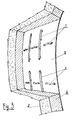
- the figures 2 and 3 show, according to this invention, how to ensure and heighten the bond between the metal structure and the hot blown bitumen filler.
- This bond is improved by structural shapes properly secured by welding to the outer surface of the plates 5 and in the drawings, these sections are consisting of properly spaced and cross-connected round bars. 7.
- This implementation is only by way of example and informative since the structural shapes may be of any kind (flats, angle or Z-shaped etc.) and may be placed in any horizontal or transverse direction as shown in the drawings or even raking.
- cylindrical tanks with horizontal axis is also valid for tanks of any other configuration and implementation (whether upright, subvertical, spherical etc.).
Landscapes
- Engineering & Computer Science (AREA)
- Mechanical Engineering (AREA)
- Filling Or Discharging Of Gas Storage Vessels (AREA)
- Underground Structures, Protecting, Testing And Restoring Foundations (AREA)
- Foundations (AREA)
- Road Paving Structures (AREA)
- Buildings Adapted To Withstand Abnormal External Influences (AREA)
- Inorganic Compounds Of Heavy Metals (AREA)
- Manufacture And Refinement Of Metals (AREA)
Abstract
Description
- This invention covers a underground storage tank for storage of liquids of any nature whatsoever.
- These tanks are usually cylindrical with horizontal axis and are consisting of an internal metal containment structure, an external static facing in touch with the soil in plain simple or reinforced concrete and a filler located between the metal containment structure and the static facing.
- Large underground storage tanks are normally built with hot press rolled metal elements or large sized rings, the transverse edges of which are provided with angle sections, apt automatically to create transverse and longitudinal channels after the rings have been jointed and with the aid of flat sections, for easy detection and sealing of any leaks .
- Such transverse channels can also be obtained with omega shapes and flat sections, welded onto the rings which, in this case, are without angle-shapes. The latter solution is preferable since hot-press rolling of the rings, stiffened by shaping, is rather difficult.
- These large sized metal elements allow for an easier and lower-cost assembly of the metal structure erected at the crown of the static concrete facing on which it is resting and which externally protects it, since handling and installation of these elements is much easier and much more rational than achievable with previous assembly and erection techniques.
- The metal containment structure is supported by the static reinforced or plain concrete facing, by means of U-bolts and a filler is poured or injected into the hollow space between metal structure and static facing
The static stability of these large underground tanks is currently guaranteed by providing the metal structure and the static facing with a separate static stability without taking their reciprocal interaction into account. An important advantage in building such large sized underground tanks can be achieved if the system is conceived as a metal containment structure, static facing, filler and surrounding soil, i.e. as one single interacting complex structure so that all its components are all together and directly contributing to the structural stability of these tanks which will thus be configurated according to the underground cavity-walled storage tank design. - By meeting this requirement, the resistance parameters and thickness of the metal structure and of the static facing may be reduced by reducing the quantity of material.
- These tanks, thus designed, are known from EP-A-0325683 and its related US-A-4915545, in which a special hot blown bitumen is injected between the static facing and the metal shell at a temperature of about 200-200°C.
- The construction of such underground storage tanks, according to these known patents is therefore rather inexpensive and stress resisting, including seismic stresses, but this invention has the aim to provide an even even better structural stability to the three tank components, i.e. its static facing, metal shell and hot blown bitumen filler.
- The metal shell is indeed the tank component most exposed to stresses and strains, especially during filling and emptying of the tank. Such strains in the metal shell will generate deformation of the filler, although these strains are usually well absorbed since hot blown bitumen is used as a filler, having excellent viscous-elastic properties.
- To ensure a continuous, close and optimum bond between blown bitumen and metal shell so as to obtain a uniform structural assembly of the three tank components, the outer surface of the metal rings forming the shell, according to this invention, is designed to improve the bond between metal shell and hot blown bitumen, by means of structural shapes of various kinds, externally welded onto the rings.
- The invention in question is illustrated in its practical and exemplifying implementation in the enclosed drawings, in which:
- Fig.1 shows a schematic cross section of an underground storage tank;
- Fig.2 shows a perspective view of a ring of the metal structure;
- Fig.3 shows an exploded view of the tank components with a ring featuring external structural shapes to improve the bond between the bitumen filler and the plates.
- With reference to fig. 1, 1 indicates the metal structure of the tank, 2 the static facing in plain or reinforced concrete, 3 the surrounding soil. The metal structure 1 is supported inside the static facing 2 by insulating U-bolts secured to the external facing 2.
- The
filler 4 is to be located between the metal structure 1 and the static facing 2; the filler is to be hot poured or injected through openings in the metal structure 1 which openings will be closed afterwards. The stresses and strains in the metal structure 1 shall be transmitted through thefiller 4 to the static facing 2 and vice-versa and it has been found that hot blown bitumen is particularly suitable for this purpose, since it has the following average characteristics:- penetration depth at 25°C 20 - 30 dmm - softening point 80° - 115°C - Fraas breakpoint -5° - 12°C - ductility at 25°C min. 3 cm - flash point min.240°-260°C - specific gravity at 25/25°C 1.01-1.05 gr/cm3 - After cooling down, this blown bitumen, has sufficient plasticity to transmit the stresses without causing permanent deformation and without breaking, to the tank components and the bitumen is poured into the hollow space at a temperature ranging between 200° and 220°C so as completely to fill the space between the metal structure and the static facing.
- As said before, the utilization of this filler guarantees the overall stability of the tank with its metal structure and static facing, the main sections of which may be calculated for a lower strength than currently required by design criteria and, because of the excellent visco-elastic properties of blown bitumen, the metal containment structure will be no longer subject to the stresses caused by soil deformation in case of of seismic waves.
- The figures 2 and 3 show, according to this invention, how to ensure and heighten the bond between the metal structure and the hot blown bitumen filler. This bond is improved by structural shapes properly secured by welding to the outer surface of the
plates 5 and in the drawings, these sections are consisting of properly spaced and cross-connected round bars. 7. This implementation is only by way of example and informative since the structural shapes may be of any kind (flats, angle or Z-shaped etc.) and may be placed in any horizontal or transverse direction as shown in the drawings or even raking. - Furthermore, externally projecting elements may be welded onto the plates. Obviously, this description given for the longitudinal shell is also valid for its front and rear header, whether flat or crowned.
- No need to say that the description regarding cylindrical tanks with horizontal axis is also valid for tanks of any other configuration and implementation (whether upright, subvertical, spherical etc.).
Claims (3)
- Underground storage tank consisting of an internal metal structure (1) formed by large sized hot-press rolled rings (5), of a static external facing (2) in reinforced or plain concrete and of a filler (4) such as hot blown bitumen located between the metal structure (1) and the static facing (2), characterized by the fact that structural shapes (7) are welded onto the outer surface of the rings (5), properly spaced and cross connected to increase the bond between the metal structure (1) and the filler (4).
- Underground storage tank as described in claim 1, characterized by the fact that the structural shapes (7) may be of any kind, such as round bars, flats, angle or Z-shaped etc. and may be placed in any horizontal, transverse or raking position.
- Underground storage tank as described in claim 2, characterized by the fact that the structural shapes (7) may be projecting and located anywhere on the outer ring surface (5).
Applications Claiming Priority (2)
| Application Number | Priority Date | Filing Date | Title |
|---|---|---|---|
| ITGE920051 | 1992-04-28 | ||
| ITGE920051A IT1257338B (en) | 1992-04-28 | 1992-04-28 | TANK-CAVE IN A STRUCTURAL COMPLEX CONSISTING OF THE STATIC FACING, THE OXIDIZED BITUMEN, THE METALLIC CONTAINMENT STRUCTURE AND THE SURROUNDING SOIL, INTERACTING WITH EACH OTHER, ALSO USABLE IN SEISMIC AREA. |
Publications (3)
| Publication Number | Publication Date |
|---|---|
| EP0567902A2 true EP0567902A2 (en) | 1993-11-03 |
| EP0567902A3 EP0567902A3 (en) | 1994-06-01 |
| EP0567902B1 EP0567902B1 (en) | 1996-07-10 |
Family
ID=11354265
Family Applications (1)
| Application Number | Title | Priority Date | Filing Date |
|---|---|---|---|
| EP93106411A Expired - Lifetime EP0567902B1 (en) | 1992-04-28 | 1993-04-19 | Underground storage tank consisting of an internal metal structure of a static external facing and of a filler with increased bond between the metal structure and the filler |
Country Status (7)
| Country | Link |
|---|---|
| US (1) | US5330288A (en) |
| EP (1) | EP0567902B1 (en) |
| AT (1) | ATE140201T1 (en) |
| DE (1) | DE69303536T2 (en) |
| ES (1) | ES2092168T3 (en) |
| IL (1) | IL105509A (en) |
| IT (1) | IT1257338B (en) |
Cited By (2)
| Publication number | Priority date | Publication date | Assignee | Title |
|---|---|---|---|---|
| EP0712793A1 (en) | 1994-11-17 | 1996-05-22 | Ing. Nino Ferrari - Impresa Costruzioni Generali S.r.l. | Underground tank for storage of liquids at ambient temperature and low temperature liquified gases |
| AU726440B2 (en) * | 1997-05-19 | 2000-11-09 | John Brendan Berry | Anchoring for reservoirs |
Families Citing this family (1)
| Publication number | Priority date | Publication date | Assignee | Title |
|---|---|---|---|---|
| CN112198908B (en) * | 2020-10-10 | 2025-07-22 | 中国重型机械研究院股份公司 | Device and method for adjusting liquid level of hot well tank |
Family Cites Families (7)
| Publication number | Priority date | Publication date | Assignee | Title |
|---|---|---|---|---|
| US1853224A (en) * | 1931-02-14 | 1932-04-12 | Commercial Shearing | Tunnel lining for withstanding internal pressure |
| US2080020A (en) * | 1934-08-21 | 1937-05-11 | Youngstown Steel Car Corp | Tunnel lining |
| FR2458740A1 (en) * | 1979-06-08 | 1981-01-02 | Technigaz | METHOD FOR CONSTRUCTING A LOW TEMPERATURE LIQUID STORAGE TANK |
| FR2533064B2 (en) * | 1981-11-09 | 1986-05-16 | Alsthom Atlantique | NUCLEAR PREMISES WITH BOILER AND EARTHQUAKE RESISTANT CONTAINER |
| GB2176230B (en) * | 1984-09-05 | 1988-04-07 | Neste Oy | Cistern for liquid or gas, constructed of reinforced concrete |
| DE3913253A1 (en) * | 1989-04-22 | 1990-10-25 | Holzmann Philipp Ag | CONTAINER FOR THE STORAGE OF FROZEN LIQUIDS |
| US5204054A (en) * | 1990-07-06 | 1993-04-20 | General Electric Company | Nuclear reactor pressure vessel |
-
1992
- 1992-04-28 IT ITGE920051A patent/IT1257338B/en active IP Right Grant
-
1993
- 1993-04-19 DE DE69303536T patent/DE69303536T2/en not_active Expired - Fee Related
- 1993-04-19 EP EP93106411A patent/EP0567902B1/en not_active Expired - Lifetime
- 1993-04-19 ES ES93106411T patent/ES2092168T3/en not_active Expired - Lifetime
- 1993-04-19 AT AT93106411T patent/ATE140201T1/en not_active IP Right Cessation
- 1993-04-23 IL IL10550993A patent/IL105509A/en not_active IP Right Cessation
- 1993-04-23 US US08/052,177 patent/US5330288A/en not_active Expired - Fee Related
Cited By (2)
| Publication number | Priority date | Publication date | Assignee | Title |
|---|---|---|---|---|
| EP0712793A1 (en) | 1994-11-17 | 1996-05-22 | Ing. Nino Ferrari - Impresa Costruzioni Generali S.r.l. | Underground tank for storage of liquids at ambient temperature and low temperature liquified gases |
| AU726440B2 (en) * | 1997-05-19 | 2000-11-09 | John Brendan Berry | Anchoring for reservoirs |
Also Published As
| Publication number | Publication date |
|---|---|
| ES2092168T3 (en) | 1996-11-16 |
| EP0567902B1 (en) | 1996-07-10 |
| EP0567902A3 (en) | 1994-06-01 |
| ATE140201T1 (en) | 1996-07-15 |
| ITGE920051A1 (en) | 1993-10-28 |
| IT1257338B (en) | 1996-01-15 |
| DE69303536T2 (en) | 1997-02-20 |
| IL105509A (en) | 1996-01-31 |
| US5330288A (en) | 1994-07-19 |
| ITGE920051A0 (en) | 1992-04-28 |
| DE69303536D1 (en) | 1996-08-14 |
Similar Documents
| Publication | Publication Date | Title |
|---|---|---|
| CN107740420A (en) | Foundation ditch tears support and support replacement system and method open | |
| EP0567902B1 (en) | Underground storage tank consisting of an internal metal structure of a static external facing and of a filler with increased bond between the metal structure and the filler | |
| EP0140937B1 (en) | Concrete-filled structural tube with cantilevers, particularly for balcony floors | |
| EP0325683B1 (en) | Large sized underground storage tank with structural stability provided by the interaction between the metal shell, the static concrete facing and the filling in the hollow between these two surfaces | |
| US4109438A (en) | Reinforced separable sectional hermetic protective covering | |
| CN211286213U (en) | Simple and easy formula of piecing together soon has hollow superstructure of muscle net to fill case | |
| CA2094734A1 (en) | Underground storage tank consisting of an internal metal structure of a static external facing and of a filler with increased bond between the metal structure and the filler | |
| US4631892A (en) | Composite bearing column | |
| CN112359867A (en) | Enclosure structure for auxiliary structure of underground station | |
| DE69501709T2 (en) | Underground tank for storing liquids at room temperature and gases liquefied at low temperatures | |
| CN218758070U (en) | Ultralow energy consumption building outer wall | |
| JP2576929B2 (en) | How to connect PC dike and base plate | |
| CN213062121U (en) | Basement outer wall expansion joint structure convenient to construction and waterproof | |
| US3377808A (en) | Cap assembly for pile shell | |
| US1186592A (en) | Hollow-wall construction. | |
| CN217872512U (en) | Steel skeleton texture of high strength explosion vent | |
| CN222745098U (en) | Absorption high tower anti-tilting lightning protection foundation | |
| CN220704823U (en) | Assembled antiknock wall | |
| CN221095499U (en) | Shock absorption and isolation filling wall for frame structure house | |
| CN218293039U (en) | Iron tower body safety device | |
| RU214525U1 (en) | Cellar | |
| CN214117746U (en) | A install guardrail fast for steel sheet pile | |
| JP3222597B2 (en) | Concrete structures in the containment vessel | |
| CN211646934U (en) | Heat-insulation building block with steel skeleton structure | |
| CN211815670U (en) | Anti-falling high-speed rail platform |
Legal Events
| Date | Code | Title | Description |
|---|---|---|---|
| PUAI | Public reference made under article 153(3) epc to a published international application that has entered the european phase |
Free format text: ORIGINAL CODE: 0009012 |
|
| AK | Designated contracting states |
Kind code of ref document: A2 Designated state(s): AT BE CH DE DK ES FR GB GR IE LI LU NL PT SE |
|
| PUAL | Search report despatched |
Free format text: ORIGINAL CODE: 0009013 |
|
| AK | Designated contracting states |
Kind code of ref document: A3 Designated state(s): AT BE CH DE DK ES FR GB GR IE LI LU NL PT SE |
|
| 17P | Request for examination filed |
Effective date: 19940711 |
|
| 17Q | First examination report despatched |
Effective date: 19951023 |
|
| GRAG | Despatch of communication of intention to grant |
Free format text: ORIGINAL CODE: EPIDOS AGRA |
|
| GRAH | Despatch of communication of intention to grant a patent |
Free format text: ORIGINAL CODE: EPIDOS IGRA |
|
| GRAA | (expected) grant |
Free format text: ORIGINAL CODE: 0009210 |
|
| AK | Designated contracting states |
Kind code of ref document: B1 Designated state(s): AT BE CH DE DK ES FR GB GR IE LI LU NL PT SE |
|
| PG25 | Lapsed in a contracting state [announced via postgrant information from national office to epo] |
Ref country code: NL Free format text: LAPSE BECAUSE OF FAILURE TO SUBMIT A TRANSLATION OF THE DESCRIPTION OR TO PAY THE FEE WITHIN THE PRESCRIBED TIME-LIMIT Effective date: 19960710 Ref country code: LI Effective date: 19960710 Ref country code: GR Free format text: LAPSE BECAUSE OF FAILURE TO SUBMIT A TRANSLATION OF THE DESCRIPTION OR TO PAY THE FEE WITHIN THE PRESCRIBED TIME-LIMIT Effective date: 19960710 Ref country code: DK Effective date: 19960710 Ref country code: CH Effective date: 19960710 Ref country code: BE Effective date: 19960710 Ref country code: AT Effective date: 19960710 |
|
| REF | Corresponds to: |
Ref document number: 140201 Country of ref document: AT Date of ref document: 19960715 Kind code of ref document: T |
|
| REG | Reference to a national code |
Ref country code: IE Ref legal event code: FG4D Free format text: 69081 |
|
| GRAH | Despatch of communication of intention to grant a patent |
Free format text: ORIGINAL CODE: EPIDOS IGRA |
|
| REF | Corresponds to: |
Ref document number: 69303536 Country of ref document: DE Date of ref document: 19960814 |
|
| PG25 | Lapsed in a contracting state [announced via postgrant information from national office to epo] |
Ref country code: PT Effective date: 19961010 |
|
| ET | Fr: translation filed | ||
| REG | Reference to a national code |
Ref country code: ES Ref legal event code: FG2A Ref document number: 2092168 Country of ref document: ES Kind code of ref document: T3 |
|
| NLV1 | Nl: lapsed or annulled due to failure to fulfill the requirements of art. 29p and 29m of the patents act | ||
| REG | Reference to a national code |
Ref country code: CH Ref legal event code: PL |
|
| PG25 | Lapsed in a contracting state [announced via postgrant information from national office to epo] |
Ref country code: IE Free format text: LAPSE BECAUSE OF NON-PAYMENT OF DUE FEES Effective date: 19970419 |
|
| PG25 | Lapsed in a contracting state [announced via postgrant information from national office to epo] |
Ref country code: LU Free format text: LAPSE BECAUSE OF NON-PAYMENT OF DUE FEES Effective date: 19970430 |
|
| PLBE | No opposition filed within time limit |
Free format text: ORIGINAL CODE: 0009261 |
|
| 26N | No opposition filed | ||
| REG | Reference to a national code |
Ref country code: GB Ref legal event code: IF02 |
|
| PGFP | Annual fee paid to national office [announced via postgrant information from national office to epo] |
Ref country code: GB Payment date: 20050420 Year of fee payment: 13 |
|
| PGFP | Annual fee paid to national office [announced via postgrant information from national office to epo] |
Ref country code: ES Payment date: 20050421 Year of fee payment: 13 |
|
| PGFP | Annual fee paid to national office [announced via postgrant information from national office to epo] |
Ref country code: SE Payment date: 20050425 Year of fee payment: 13 |
|
| PGFP | Annual fee paid to national office [announced via postgrant information from national office to epo] |
Ref country code: FR Payment date: 20050429 Year of fee payment: 13 |
|
| PGFP | Annual fee paid to national office [announced via postgrant information from national office to epo] |
Ref country code: DE Payment date: 20050616 Year of fee payment: 13 |
|
| PG25 | Lapsed in a contracting state [announced via postgrant information from national office to epo] |
Ref country code: GB Free format text: LAPSE BECAUSE OF NON-PAYMENT OF DUE FEES Effective date: 20060419 |
|
| PG25 | Lapsed in a contracting state [announced via postgrant information from national office to epo] |
Ref country code: SE Free format text: LAPSE BECAUSE OF NON-PAYMENT OF DUE FEES Effective date: 20060420 Ref country code: ES Free format text: LAPSE BECAUSE OF NON-PAYMENT OF DUE FEES Effective date: 20060420 |
|
| PG25 | Lapsed in a contracting state [announced via postgrant information from national office to epo] |
Ref country code: DE Free format text: LAPSE BECAUSE OF NON-PAYMENT OF DUE FEES Effective date: 20061101 |
|
| EUG | Se: european patent has lapsed | ||
| GBPC | Gb: european patent ceased through non-payment of renewal fee |
Effective date: 20060419 |
|
| REG | Reference to a national code |
Ref country code: FR Ref legal event code: ST Effective date: 20061230 |
|
| REG | Reference to a national code |
Ref country code: ES Ref legal event code: FD2A Effective date: 20060420 |
|
| PG25 | Lapsed in a contracting state [announced via postgrant information from national office to epo] |
Ref country code: FR Free format text: LAPSE BECAUSE OF NON-PAYMENT OF DUE FEES Effective date: 20060502 |