EP0567799B1 - Apparatus for data reception - Google Patents
Apparatus for data reception Download PDFInfo
- Publication number
- EP0567799B1 EP0567799B1 EP93105480A EP93105480A EP0567799B1 EP 0567799 B1 EP0567799 B1 EP 0567799B1 EP 93105480 A EP93105480 A EP 93105480A EP 93105480 A EP93105480 A EP 93105480A EP 0567799 B1 EP0567799 B1 EP 0567799B1
- Authority
- EP
- European Patent Office
- Prior art keywords
- word
- syndromes
- data word
- data
- syndrome
- Prior art date
- Legal status (The legal status is an assumption and is not a legal conclusion. Google has not performed a legal analysis and makes no representation as to the accuracy of the status listed.)
- Expired - Lifetime
Links
Images


Classifications
-
- H—ELECTRICITY
- H03—ELECTRONIC CIRCUITRY
- H03M—CODING; DECODING; CODE CONVERSION IN GENERAL
- H03M13/00—Coding, decoding or code conversion, for error detection or error correction; Coding theory basic assumptions; Coding bounds; Error probability evaluation methods; Channel models; Simulation or testing of codes
- H03M13/03—Error detection or forward error correction by redundancy in data representation, i.e. code words containing more digits than the source words
- H03M13/05—Error detection or forward error correction by redundancy in data representation, i.e. code words containing more digits than the source words using block codes, i.e. a predetermined number of check bits joined to a predetermined number of information bits
- H03M13/13—Linear codes
-
- H—ELECTRICITY
- H04—ELECTRIC COMMUNICATION TECHNIQUE
- H04B—TRANSMISSION
- H04B1/00—Details of transmission systems, not covered by a single one of groups H04B3/00 - H04B13/00; Details of transmission systems not characterised by the medium used for transmission
- H04B1/06—Receivers
-
- H—ELECTRICITY
- H03—ELECTRONIC CIRCUITRY
- H03M—CODING; DECODING; CODE CONVERSION IN GENERAL
- H03M13/00—Coding, decoding or code conversion, for error detection or error correction; Coding theory basic assumptions; Coding bounds; Error probability evaluation methods; Channel models; Simulation or testing of codes
- H03M13/37—Decoding methods or techniques, not specific to the particular type of coding provided for in groups H03M13/03 - H03M13/35
- H03M13/45—Soft decoding, i.e. using symbol reliability information
-
- H—ELECTRICITY
- H04—ELECTRIC COMMUNICATION TECHNIQUE
- H04H—BROADCAST COMMUNICATION
- H04H2201/00—Aspects of broadcast communication
- H04H2201/10—Aspects of broadcast communication characterised by the type of broadcast system
- H04H2201/13—Aspects of broadcast communication characterised by the type of broadcast system radio data system/radio broadcast data system [RDS/RBDS]
Definitions
- the invention is based on a device according to the type of the main claim, the data being transmitted by means of radio waves, in particular together with other information.
- an auxiliary carrier is modulated with digitally coded signals, specifically the data are transmitted in groups of four data words, one data word each consisting of an information word of 16 bits and a test word of 10 bits.
- the test word is formed from the information word according to a predetermined algorithm, with a so-called offset word which is used for synchronization being superimposed on the actual test word.
- a binary reliability signal is derived, in which 1 bit within a reliability word is assigned to a bit of the data word.
- the known error correction is a so-called erasure correction, which means that only bits marked as bad or suspicious are permitted for modification for the purpose of correction. All combinations with the exception of the zero combination are checked to determine whether the syndrome resulting from the combination in question either corresponds to the error syndrome found (then a correction is possible) or has the value zero (then the correction is not clear). Therefore, the correction is not made in the latter case. Incorrect but well-marked bits lead to a block that cannot be corrected correctly.
- the object of the present invention is to avoid that incorrect bits, but which are referred to as well in the reliability word, lead to an incorrect correction.
- the device according to the invention with the characterizing features of the main claim has the advantage that a significant improvement in error correction is possible only with extremely little additional effort. The number of occurrences Incorrect corrections can be significantly reduced.
- FIG. 1 shows a device according to the invention in a highly simplified manner, only the parts necessary for understanding being shown. Further details, for example on demodulation and word or bit synchronization, are adequately described in the literature, in particular in the EBU publication mentioned at the beginning. Furthermore, for the sake of clarity, the time sequence for signal processing was not taken into account in detail in the illustration according to FIG. 1.
- the output signal of a demodulator is fed via input 1 to the enable (enable) input of a 6-bit counter 2.
- the 6-bit counter 2 is clocked with a signal T 57 , the frequency of which corresponds to the subcarrier frequency of 57 kHz in the exemplary embodiment.
- the 6-bit counter 2 With the bit clock T supplied at 7, the 6-bit counter 2 is set to an initial value.
- the counter reading reached before the setting results in a data signal X and a reliability signal Q.
- the counter is set to the initial value 8 and counts up to 55, ie by 48, since the RDS system Subcarrier frequency corresponds to 48 times the bit frequency.
- the threshold for forming the data signal X lies in the middle of the total range, so that the most significant bit (MSB) of the counter reading can be used directly as the data signal X.
- the upper and lower threshold for the reliability signal include the threshold for the data signal. Between the upper and the lower threshold, the second and the third bit of the counter reading are the same, while below and above these thresholds the second and the third bit are different. It is therefore possible to derive the reliability signal Q using an exclusive-OR circuit 3.
- the bits of the data signal X which are only briefly present at the end of each bit period are fed to a differential decoder consisting of two data flip-flops 4 and 5 and an exclusive-OR circuit 6.
- the flip-flops are triggered with the bit clock T supplied at 7, so that with the aid of the data flip-flops 4, 5 the binary signal is delayed by one clock period.
- the exclusive-OR circuit 6 outputs a 1 if two successive bits of the received signal have different values.
- the information is sent in data words, four of which form a group.
- Each of the data words consists of an information word with 16 bits and a check word of 10 bits, so that the total length of the data word is 26 bits.
- a syndrome S Y is formed from the data word Y present at the output of the differential decoder in a manner known per se at 8.
- the data word Y or its information part is passed either directly or via the AND circuit 9 and the OR circuit 10 to the output 11, from which it is used for further processing, for example for a display , can be directed, or retained if it is unusable.
- the data word is corrected using the exclusive-OR circuit 12 and passed to the output 11 via the AND circuit 13 and the OR circuit 10.
- a data flip-flop 14 is connected to the output of the exclusive-OR circuit 3 and is also clocked with the clock T supplied at 7.
- a digital signal Q is then present at the output of the data flip-flop 14, in which a bit is assigned to a bit of the signal Y in each case. This signal characterizes the reliability or the unreliability of the individual bits of the signal Y before the differential coding.
- a counting and comparison circuit 15 determines whether the number F of the unreliability bits is greater than a predetermined value F m , the value 6 being possible for F m, for example. If this is the case, the circuit 15 outputs a 1, which is inverted at 16, so that the forwarding of the data word by the AND circuit 9 is prevented - regardless of what the evaluation results in detail.
- a syndrome is retrieved from a matrix K, stored in a memory 17 and linked in an exclusive-OR circuit 18 with another syndrome, which is located in the accumulator 19.
- a flip-flop 22 is set. The output signal of the flip-flop also prevents the forwarding of the data word to the output 11 via the AND circuit 9.
- the respective content of the accumulator 19 is compared with all rows of the matrix K if more than one of the syndromes S 1 to S F are involved in the content of the accumulator A, that is if more than one unreliability bit was used in the combination in question.
- This comparison is carried out in the device according to FIG. 1 by a device 30 which sequentially switches the individual rows of the matrix K via a changeover switch 31 of the equivalent circuit 21 feeds.
- This additional comparison must not have any consequences if only one syndrome is involved in the accumulator content, since the content of the accumulator is always equal to one row of the matrix K. It is therefore advantageous for reasons of computational complexity to make the further comparison only if several of the syndromes S 1 to S F contribute to the content of the accumulator A. If any of the combinations of the further syndromes has the value 0 or corresponds to a row of the matrix K in the case of several further syndromes, the data word is thus declared invalid.
- a further equivalence circuit 23 checks whether one of the syndromes corresponds to the syndrome S Y of the data word. If this is the case, then the flip-flop 24 is set, the non-inverted output signal of which is linked with the aid of an AND circuit 25 to the output signal of an equivalent circuit 27 which is inverted at 26.
- a 1 is present at the output of the AND circuit 25 if one of the combinations of the further syndromes S 1 to S F corresponds to the syndrome S Y of the data word Y and if no combination or the syndrome S Y is not equal to 0 and the above the test described was negative. In this case, the AND circuit 13 becomes conductive and a corrected data word is passed to the output 11.
- An error word derived with the aid of circuit 20 is used for the correction and is linked exclusively or with the data word at 12.
- An example of the circuit 20 is explained in more detail in DE 37 07 152 A1.
- the flip-flop 24 remains unset and outputs a 1 to the AND circuit 28 at its inverting output, at the output of which a signal is present if the syndrome is also present S Y is not equal to 0. This means that data word Y cannot be corrected.
- FIG. 2 shows the parity check matrix H proposed in the above-mentioned EBU publication as well as an example of a data word Y and the syndrome S Y formed from this data word and the matrix H.
- the matrix H consists of 26 rows with 10 columns each.
- the syndrome S Y for the data word Y is now calculated in such a way that all rows of the matrix H are exclusively-or-linked to one another in which the data word has the value 1.
- Multiple exclusive-or operations are known to result in a 1 if there is an odd number of ones and a 0 if there is an even number of ones.
- the syndrome is formed from the unreliability bits with the aid of a matrix K, which is partially shown in FIG. 2 and is derived from the matrix H as follows: the first and last lines correspond to the matrix H, while the lines in between each have a Exclusive OR combination of the adjacent rows of the H matrix are formed.
- the matrix K thus has 27 rows. This enables the last bit of the previous reliability word to be taken into account.
- n represents a counting variable, from which the number z is calculated according to a Gray code, which in each case indicates which of the further syndromes S 1 to S 4 are to be linked exclusively or.
- XOR abbreviation XOR.
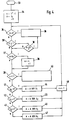
- FIG. 4 shows a flow chart for the combination of the further syndromes explained in connection with FIG. 3.
- the count variable n is set at 34 to the number of possible combinations with F unreliability bits.
- the syndrome S F is read into an accumulator A and a flag is set to 0. It is then checked at 35 whether the content of the accumulator, that is to say the syndrome S F is equal to 0 during the first program run. If this is the case, the test is terminated at 36.
- the program branches at 36 'depending on whether A corresponds to one of the rows of the matrix K. If so, the test is terminated at 36, otherwise it continues at 37.
- FIG. 5 shows the program part 36 '(FIG. 4) in somewhat more detail.
- a count variable i representing the respective line of the matrix K is set to 1 (program part 51). It is then checked at 52 whether the line with the number i corresponds to the contents of the accumulator. If applicable, the test is terminated at 36 (FIG. 4). Otherwise, the counting variable i is incremented at 53 and then compared with the number of rows of the matrix K, namely 27. The program steps 52, 53, 54 are then repeated until either one line of the matrix K corresponds to the contents of the accumulator or until line 27 is reached. The correction attempt is then either terminated at 36 or continued at 37 (FIG. 4).
- FIG. 6 shows a block diagram of an arrangement for evaluating the syndromes S Y and S 1 to S F.
- the syndromes S 1 to S F are stored in a memory 81. That too Data word Y to be checked or corrected is located in a memory 82, while the associated reliability word Q is stored at 83.
- a down counter 84 is set to an initial value n 0 , for which purpose the number F of the unreliability bits is taken from the circuit 20 (FIG. 1) and n 0 is calculated according to the equation 2 F -1.
- addresses for reading the syndromes S 1 to S F are obtained from the memory 81 by using the Gray code in accordance with the table in FIG. 3.
- An exclusive-OR circuit 86 links the syndrome supplied to it with the syndrome stored in the accumulator 87 and writes the syndrome obtained into the accumulator 87.
- the content of the accumulator 87 is compared with the aid of a comparator 88 with the value 0, which is supplied via a changeover switch 98. As soon as a syndrome or a combination of syndromes in the accumulator 87 has the value 0, the comparator emits a signal which means that the operation is terminated.
- the operation is also terminated if the content of the accumulator 87 for the case x> 1 (see FIG. 4) is equal to one row of the K matrix 99.
- the changeover switch is brought into the left position, whereupon the lines of the K matrix 99 are read out in succession.
- the content of the comparator 87 is also compared with the syndrome S Y , which is obtained in a circuit 89 from the data word Y according to the computing method shown in FIG. 2.
- a 10-bit comparator 90 is provided, the output of which is connected to a memory 91, in which a flag and a number m can be stored.
- the number m represents the state of the counter 84 at which the content of the accumulator 87 is equal to the syndrome S Y , and thus marks that combination of unreliability bits which have led to the equality between A and S Y.
- the time processes during the operation of the arrangement according to FIG. 6 are controlled by a sequence control 92.
- This is supplied, among other things, by the counter 84 with a signal when the counter reading n is 1. If this is achieved without the content A of the accumulator 87 having reached the value 0 and the flag being equal to 0, the sequence control 92 activates the dual / gray converter 93, which converts the number m according to the Gray code and feeds the sequencer 92. Those bits of the reliability word Q which indicate correctable bits of the word Y are thereby determined.
- a correction value K X comprising these bits is generated in circuit 94.
- K X is converted into K Y and in the correction circuit 96 with the data word Y exclusively-or-linked, which outputs a corrected data word Y K at its output 97.
Abstract
Description
Die Erfindung geht aus von einem Gerät nach der Gattung des Hauptanspruchs, wobei die Daten mittels Radiowellen, insbesondere zusammen mit anderen Informationen, übertragen werden.The invention is based on a device according to the type of the main claim, the data being transmitted by means of radio waves, in particular together with other information.
Der Empfang solcher Daten kann in vielfältiger Weise gestört sein. Es sind daher Verfahren und Geräte zur Feststellung und/oder Korrektur von Übertragungsfehlern bekanntgeworden. Bei dem sogenannten Radiodatensystem (RDS) wird ein Hilfsträger mit digital-codierten Signalen moduliert, und zwar werden die Daten in Gruppen von jeweils vier Datenworten übertragen, wobei jeweils ein Datenwort aus einem Informationswort von 16 Bits und einem Prüfwort von 10 Bits besteht. Das Prüfwort wird bei dem Radiodatensystem nach einem vorgegebenen Algorithmus aus dem Informationswort gebildet, wobei dem eigentlichen Prüfwort noch ein sogenanntes Offset-Wort überlagert wird, das zur Synchronisierung dient.The reception of such data can be disturbed in many ways. Methods and devices for determining and / or correcting transmission errors have therefore become known. In the so-called radio data system (RDS), an auxiliary carrier is modulated with digitally coded signals, specifically the data are transmitted in groups of four data words, one data word each consisting of an information word of 16 bits and a test word of 10 bits. In the radio data system, the test word is formed from the information word according to a predetermined algorithm, with a so-called offset word which is used for synchronization being superimposed on the actual test word.
Beim Empfang wird nach der Demodulation mit Hilfe des Prüfwortes eine Fehlerprüfung sowie eine Fehlerkorrektur vorgenommen. Eine ausführliche Beschreibung des Radiodatensystems RDS liegt in der Druckschrift vor: "Specifications of the Radio Data System RDS for VHF/FM Sound Broadcasting", Tech. 3244 - E, März 1984, herausgegeben von der European Broadcasting Union (EBU).After receiving the demodulation, an error check and error correction are carried out with the help of the check word. A detailed description of the RDS radio data system is available in the publication: "Specifications of the Radio Data System RDS for VHF / FM Sound Broadcasting", Tech. 3244-E, March 1984, issued by the European Broadcasting Union (EBU).
Bei einem bekannten Gerät zum Empfang von Daten (DE 37 07 152 A1) wird zusätzlich zu dieser Fehlerprüfung und -korrektur ein binäres Zuverlässigkeitssignal abgeleitet, bei welchem jeweils 1 Bit innerhalb eines Zuverlässigkeitswortes einem Bit des Datenwortes zugeordnet ist.In a known device for receiving data (
Die bekannte Fehlerkorrektur ist eine sogenannte Löschkorrektur, das heißt, nur als schlecht bzw. verdächtig gekennzeichnete Bits sind zur Modifikation zwecks Korrektur zugelassen. Dabei werden alle Kombinationen mit Ausnahme der Null-Kombination daraufhin geprüft, ob das aus der betreffenden Kombination resultierende Syndrom entweder dem vorgefundenen Fehlersyndrom entspricht (dann ist eine Korrektur möglich) oder den Wert Null hat (dann ist die Korrektur nicht eindeutig). Deshalb unterbleibt im letzteren Fall die Korrektur. Hierbei führen falsche, aber als gut gekennzeichnete Bits zu einem nicht richtig korrigierbaren Block.The known error correction is a so-called erasure correction, which means that only bits marked as bad or suspicious are permitted for modification for the purpose of correction. All combinations with the exception of the zero combination are checked to determine whether the syndrome resulting from the combination in question either corresponds to the error syndrome found (then a correction is possible) or has the value zero (then the correction is not clear). Therefore, the correction is not made in the latter case. Incorrect but well-marked bits lead to a block that cannot be corrected correctly.
Aufgabe der vorliegenden Erfindung ist es zu vermeiden, daß falsche, aber im Zuverlässigkeitswort als gut bezeichnete Bits zu einer falschen Korrektur führen.The object of the present invention is to avoid that incorrect bits, but which are referred to as well in the reliability word, lead to an incorrect correction.
Das erfindungsgemäße Gerät mit den kennzeichnenden Merkmalen des Hauptanspruchs hat den Vorteil, daß nur mit äußerst geringem Mehraufwand eine wesentliche Verbesserung der Fehlerkorrektur möglich ist. Die Anzahl der auftretenden Fehlkorrekturen kann dabei erheblich gesenkt werden.The device according to the invention with the characterizing features of the main claim has the advantage that a significant improvement in error correction is possible only with extremely little additional effort. The number of occurrences Incorrect corrections can be significantly reduced.
Durch die in den Unteransprüchen aufgeführten Maßnahmen sind vorteilhafte Weiterbildungen und Verbesserungen der im Hauptanspruch angegebenen Erfindung möglich.Advantageous further developments and improvements of the invention specified in the main claim are possible through the measures listed in the subclaims.
Ausführungsbeispiele der Erfindung sind in der Zeichnung anhand mehrerer Figuren dargestellt und in der nachfolgenden Beschreibung näher erläutert. Es zeigt:
- Fig. 1
- ein Blockschaltbild eines erfindungsgemäßen Gerätes,
- Fig. 2
- eine schematische Darstellung der Ableitung eines Syndroms,
- Fig. 3
- eine tabellarische Darstellung zur Erläuterung der Ableitung der Kombinationen weiterer Syndrome,
- Fig. 4
- ein Flußdiagramm für einen in einem erfindungsgemäßen Gerät enthaltenen Mikrocomputer,
- Fig. 5
- ein Detail des Flußdiagramms nach Fig. 4 und
- Fig. 6
- ein Blockschaltbild einer Anordnung zur Auswertung der Syndrome und zur Fehlerkorrektur.
- Fig. 1
- 2 shows a block diagram of a device according to the invention,
- Fig. 2
- a schematic representation of the derivation of a syndrome,
- Fig. 3
- a tabular representation to explain the derivation of the combinations of further syndromes,
- Fig. 4
- 2 shows a flow chart for a microcomputer contained in a device according to the invention,
- Fig. 5
- a detail of the flow chart of FIGS. 4 and
- Fig. 6
- a block diagram of an arrangement for evaluating the syndromes and for error correction.
Das Blockschaltbild gemäß Fig. 1 zeigt in stark vereinfachter Weise ein erfindungsgemäßes Gerät, wobei lediglich die zum Verständnis erforderlichen Teile dargestellt sind. Weitere Einzelheiten, beispielsweise bei der Demodulation und der Wort- bzw. Bitsynchronisierung, sind in der Literatur, insbesondere in der eingangs genannten Veröffentlichung der EBU, ausreichend beschrieben. Ferner wurde der Übersichtlichkeit halber bei der Darstellung gemäß Fig. 1 auf den zeitlichen Ablauf bei der Signalverarbeitung im einzelnen nicht Rücksicht genommen.1 shows a device according to the invention in a highly simplified manner, only the parts necessary for understanding being shown. Further details, for example on demodulation and word or bit synchronization, are adequately described in the literature, in particular in the EBU publication mentioned at the beginning. Furthermore, for the sake of clarity, the time sequence for signal processing was not taken into account in detail in the illustration according to FIG. 1.
Dieser wird im Zusammenhang mit anderen Figuren genauer erläutert.This is explained in more detail in connection with other figures.
Das Ausgangssignal eines nicht dargestellten Demodulators wird über den Eingang 1 dem Freigabe(Enable)-Eingang eines 6-Bit-Zählers 2 zugeführt. Der 6-Bit-Zähler 2 wird mit einem Signal T57 getaktet, dessen Frequenz bei dem Ausführungsbeispiel der Hilfsträgerfrequenz von 57 kHz entspricht. Mit dem bei 7 zugeführten Bit-Takt T wird der 6-Bit-Zähler 2 auf einen Anfangswert gesetzt. Der jeweils vor dem Setzen erreichte Zählerstand ergibt nach der in Fig. 1a) dargestellten Tabelle ein Datensignal X und ein Zuverlässigkeitssignal Q. Dabei wird der Zähler auf den Anfangswert 8 gesetzt und zählt bis 55, also um 48 weiter, da beim RDS-System die Hilfsträgerfrequenz dem 48-fachen der Bitfrequenz entspricht.The output signal of a demodulator, not shown, is fed via
Die Schwelle zur Bildung des Datensignals X liegt bei der Tabelle nach Fig. 1a) in der Mitte des Gesamtbereichs, so daß das höchstwertige Bit (MSB) des Zählerstandes direkt als Datensignal X verwendet werden kann. Die obere und die untere Schwelle für das Zuverlässigkeitssignal schließen die Schwelle für das Datensignal ein. Zwischen der oberen und der unteren Schwelle sind jeweils das zweite und das dritte Bit des Zählerstandes gleich, während unterhalb bzw. oberhalb dieser Schwellen das zweite und das dritte Bit verschieden sind. Es ist daher möglich, mit Hilfe einer Exklusiv-Oder-Schaltung 3 das Zuverlässigkeitssignal Q abzuleiten.In the table according to FIG. 1a), the threshold for forming the data signal X lies in the middle of the total range, so that the most significant bit (MSB) of the counter reading can be used directly as the data signal X. The upper and lower threshold for the reliability signal include the threshold for the data signal. Between the upper and the lower threshold, the second and the third bit of the counter reading are the same, while below and above these thresholds the second and the third bit are different. It is therefore possible to derive the reliability signal Q using an exclusive-
Die am Ende jeweils einer Bitperiode nur kurzzeitig anstehenden Bits des Datensignals X werden einem aus zwei Daten-Flip-Flops 4 und 5 sowie einer Exklusiv-Oder-Schaltung 6 bestehenden Differentialdecoder zugeführt. Die Flip-Flops werden mit dem bei 7 zugeführten Bit-Takt T getriggert, so daß mit Hilfe der Daten-Flip-Flops 4, 5 das binäre Signal jeweils um eine Taktperiode verzögert wird. Die Exklusiv-Oder-Schaltung 6 gibt eine 1 ab, wenn zwei aufeinanderfolgende Bits des empfangenen Signals verschiedene Werte aufweisen.The bits of the data signal X which are only briefly present at the end of each bit period are fed to a differential decoder consisting of two data flip-flops 4 and 5 and an exclusive-
Bei dem Radiodatensystem werden die Informationen in Datenworten gesendet, von denen jeweils vier eine Gruppe bilden. Jedes der Datenworte besteht aus einem Informationswort mit 16 Bits und einem Prüfwort von 10 Bits, so daß die gesamte Länge des Datenwortes 26 Bits beträgt.In the radio data system, the information is sent in data words, four of which form a group. Each of the data words consists of an information word with 16 bits and a check word of 10 bits, so that the total length of the data word is 26 bits.
Aus dem am Ausgang des Differentialdecoders anstehenden Datenwort Y wird in an sich bekannter Weise bei 8 ein Syndrom SY gebildet. In Abhängigkeit vom Wert dieses Syndroms sowie der Werte weiterer Syndrome wird das Datenwort Y bzw. dessen Informationsteil entweder direkt oder über die UND-Schaltung 9 und die Oder-Schaltung 10 zum Ausgang 11 geleitet, von dem es zur weiteren Verarbeitung, beispielsweise für eine Anzeige, geleitet werden kann, oder zurückgehalten wird, wenn es unbrauchbar ist. Für den Fall von korrigierbaren Fehlern wird das Datenwort mit Hilfe der Exklusiv-Oder-Schaltung 12 korrigiert und über die UND-Schaltung 13 und die Oder-Schaltung 10 zum Ausgang 11 geleitet.A syndrome S Y is formed from the data word Y present at the output of the differential decoder in a manner known per se at 8. Depending on the value of this syndrome and the values of further syndromes, the data word Y or its information part is passed either directly or via the
An den Ausgang der Exklusiv-Oder-Schaltung 3 ist ein Daten-Flip-Flop 14 angeschlossen, welches ebenfalls mit dem bei 7 zugeführten Takt T getaktet wird. Am Ausgang des Daten-Flip-Flops 14 steht dann ein digitales Signal Q an, bei welchem jeweils ein Bit einem Bit des Signals Y zugeordnet ist. Dieses Signal kennzeichnet die Zuverlässigkeit bzw. die Unzuverlässigkeit der einzelnen Bits des Signals Y vor der Differentialcodierung.A data flip-
Da der Aufwand für die Auswertung des Zuverlässigkeitssignals stark mit der Anzahl der Unzuverlässigkeitsbits ansteigt und außerdem wegen der geringen Hamming-Distanz des für das Radiodatensystem gewählten Codes eine Korrektur vieler Fehler ohnehin nicht möglich ist, wird von vornherein die Auswertung eines Datenwortes, bei welchem das Zuverlässigkeitswort zuviele Unzuverlässigkeitsbits enthält, abgebrochen. Bei dem Ausführungsbeispiel gemäß Fig. 1 wird daher in einer Zähl- und Vergleichsschaltung 15 festgestellt, ob die Zahl F der Unzuverlässigkeitsbits größer als ein vorgegebener Wert Fm ist, wobei für Fm beispielsweise der Wert 6 in Frage kommt. Ist dieses der Fall, so wird von der Schaltung 15 eine 1 abgegeben, welche bei 16 invertiert wird, so daß die Weiterleitung des Datenwortes durch die UND-Schaltung 9 unterbunden wird - unabhängig davon, was die Auswertung im einzelnen ergibt.Since the effort for evaluating the reliability signal increases sharply with the number of unreliability bits and, because of the short Hamming distance of the code selected for the radio data system, it is not possible to correct many errors anyway, the evaluation of a data word in which the reliability word is used is carried out from the start contains too many unreliability bits, aborted. In the exemplary embodiment according to FIG. 1, it is therefore determined in a counting and
Für jedes Unzuverlässigkeitsbit wird aus einer Matrix K ein Syndrom abgerufen, in einem Speicher 17 abgelegt und in einer Exklusiv-Oder-Schaltung 18 mit einem anderen Syndrom verknüpft, welches sich im Akkumulator 19 befindet. Sobald eine der Kombinationen den Wert 0 aufweist, was in einer Äquivalenzschaltung 21 festgestellt wird, wird ein Flip-Flop 22 gesetzt. Das Ausgangssignal des Flip-Flops verhindert über die UND-Schaltung 9 ebenfalls die Weiterleitung des Datenwortes zum Ausgang 11.For each unreliability bit, a syndrome is retrieved from a matrix K, stored in a
Zusätzlich wird der jeweilige Inhalt des Akkumulators 19 mit allen Zeilen der Matrix K verglichen, wenn mehr als eines der Syndrome S1 bis SF am Inhalt des Akkumulators A beteiligt sind, wenn also mehr als ein Unzuverlässigkeitsbit in der betreffenden Kombination verwendet wurden. Dieser Vergleich erfolgt bei dem Gerät nach Fig. 1 durch eine Einrichtung 30, welche nacheinander die einzelnen Zeilen der Matrix K über einen Umschalter 31 der Äquivalenzschaltung 21 zuführt. Dieser zusätzliche Vergleich darf bei der Beteiligung von nur einem Syndrom an dem Akkumulatorinhalt keine Folgen haben, da der Inhalt des Akkumulators immer gleich einer Zeile der Matrix K ist. Deshalb ist es aus Gründen des Rechenaufwandes vorteilhaft, den weiteren Vergleich nur vorzunehmen, wenn mehrere der Syndrome S1 bis SF zum Inhalt des Akkumulators A beitragen. Wenn irgendeine der Kombinationen der weiteren Syndrome also den Wert 0 aufweist oder im Falle mehrerer weiterer Syndrome einer Zeile der Matrix K entspricht, wird das Datenwort somit für ungültig erklärt.In addition, the respective content of the
In einer weiteren Äquivalenzschaltung 23 wird geprüft, ob eines der Syndrome dem Syndrom SY des Datenwortes entspricht. Ist dieses der Fall, so wird das Flip-Flop 24 gesetzt, dessen nichtinvertiertes Ausgangssignal mit Hilfe einer UND-Schaltung 25 mit dem bei 26 invertierten Ausgangssignal einer Äquivalenzschaltung 27 verknüpft wird. Am Ausgang der UND-Schaltung 25 steht dann eine 1 an, wenn eine der Kombinationen der weiteren Syndrome S1 bis SF dem Syndrom SY des Datenwortes Y entspricht und wenn keine Kombination bzw. das Syndrom SY nicht gleich 0 ist und die oben beschriebene Prüfung negativ verlaufen ist. In diesem Fall wird die UND-Schaltung 13 leitend und ein korrigiertes Datenwort wird zum Ausgang 11 geleitet. Zur Korrektur dient ein mit Hilfe der Schaltung 20 abgeleitetes Fehlerwort, das bei 12 mit dem Datenwort exklusiv-oder-verknüpft wird. Ein Beispiel für die Schaltung 20 ist in DE 37 07 152 A1 näher erläutert.A
Ist keine der Kombinationen der weiteren Syndrome gleich dem Syndrom SY des Datenwortes, so bleibt das Flip-Flop 24 ungesetzt und gibt an seinem invertierenden Ausgang eine 1 an die UND-Schaltung 28 ab, an deren Ausgang ein Signal ansteht, wenn außerdem das Syndrom SY ungleich 0 ist. Dieses bedeutet, daß das Datenwort Y nicht korrigierbar ist.If none of the combinations of the other syndromes is equal to the syndrome S Y of the data word, the flip-
In der folgenden Tabelle sind die im Zusammenhang mit Fig. 1 beschriebenen verschiedenen Möglichkeiten zusammengestellt:
Zur Erläuterung der Syndrombildung ist in Fig. 2 die in der obengenannten EBU-Veröffentlichung vorgeschlagene Paritätsprüfmatrix H sowie ein Beispiel eines Datenwortes Y und des aus diesem Datenwort und der Matrix H gebildeten Syndroms SY dargestellt. Die Matrix H besteht aus 26 Zeilen mit jeweils 10 Spalten. Die Berechnung des Syndroms SY für das Datenwort Y erfolgt nun derart, daß alle Zeilen der Matrix H miteinander exklusiv-oder-verknüpft werden, bei welchen das Datenwort den Wert 1 aufweist. Durch die mehrfache Exklusiv-Oder-Verknüpfung ergibt sich bekanntlich bei Vorliegen einer ungeraden Anzahl von Einsen eine 1 und bei einer geraden Anzahl von Einsen eine 0.To explain the syndrome formation, FIG. 2 shows the parity check matrix H proposed in the above-mentioned EBU publication as well as an example of a data word Y and the syndrome S Y formed from this data word and the matrix H. The matrix H consists of 26 rows with 10 columns each. The syndrome S Y for the data word Y is now calculated in such a way that all rows of the matrix H are exclusively-or-linked to one another in which the data word has the
Durch die Differential-Codierung entstehen aus einem 1-Bit-Fehler des Signals auf der Übertragungsstrecke 2-Bit-Fehler bei dem Datenwort Y. Bei der Erzeugung des Zuverlässigkeitswortes Q wird die Dauer der Fehler auf der Übertragungsstrecke nicht vergrößert, so daß jeweils ein einzelnes Unzuverlässigkeitsbit auf einen 1-Bit-Fehler auf der Übertragungsstrecke, also auf einen 2-Bit-Fehler im Datenwort Y hinweist. Aus diesem Grunde erfolgt die Syndrombildung aus den Unzuverlässigkeitsbits mit Hilfe einer Matrix K, welche in Fig. 2 teilweise dargestellt und aus der Matrix H wie folgt abgeleitet ist: Die erste und die letzte Zeile entsprechen der Matrix H, während die dazwischenliegenden Zeilen jeweils durch eine Exklusiv-Oder-Verknüpfung der benachbarten Zeilen der H-Matrix gebildet sind. Die Matrix K weist somit 27 Zeilen auf. Dieses ermöglicht die Berücksichtigung des letzten Bits des vorangegangenen Zuverlässigkeitswortes.Due to the differential coding, a 1-bit error of the signal on the transmission link results in 2-bit errors in the data word Y. When the reliability word Q is generated, the duration of the errors on the transmission link is not increased, so that a single one Unreliability bit indicates a 1-bit error on the transmission link, i.e. a 2-bit error in data word Y. For this reason, the syndrome is formed from the unreliability bits with the aid of a matrix K, which is partially shown in FIG. 2 and is derived from the matrix H as follows: the first and last lines correspond to the matrix H, while the lines in between each have a Exclusive OR combination of the adjacent rows of the H matrix are formed. The matrix K thus has 27 rows. This enables the last bit of the previous reliability word to be taken into account.
Mit Hilfe der Matrix K werden die Syndrome aller einzelnen Unzuverlässigkeitsbits gebildet und bei 17 (Fig. 1) abgespeichert. Der Rechenaufwand zur Exklusiv-Oder-Verknüpfung der Syndrome S1 bis SF kann erheblich reduziert werden, wenn gemäß Fig. 3 vorgegangen wird.With the help of the matrix K, the syndromes of all individual unreliability bits are formed and stored at 17 (FIG. 1). The computing effort for the exclusive-OR linkage of the syndromes S 1 to S F can be considerably reduced if the procedure according to FIG. 3 is used.
Es wird dabei von maximal vier auszuwertenden Unzuverlässigkeitsbits ausgegangen. Die Zahl n stellt eine Zählvariable dar, aus welcher nach einem Gray-Code die Zahl z errechnet wird, die jweils angibt, welche der weiteren Syndrome S1 bis S4 exklusiv-oder zu verknüpfen sind. Der Einfachheit halber wurde eine Exklusiv-Oder-Verknüpfung in der Zeichnung durch die Abkürzung XOR dargestellt. Dabei bewirkt die Anwendung des Gray-Codes, bei dem sich von Zeile zu Zeile immer nur ein Bit ändert, daß vom Speicher 17 in die Exklusiv-Oder-Verknüpfung 18 für jeden neuen Rechenschritt nur ein neues Syndrom übernommen wird. Dabei wird bei n = 15 das Syndrom S4 ohne Verknüpfung an den Ausgang der Schaltung 19 (Fig. 1) weitergeleitet; bei n = 14 (= 1110) werden die Syndrome bis S1 und S4 miteinander verknüpft, danach wird zusätzlich das Syndrom S2 aus dem Speicher gelesen und mit den Syndromen S1 und S4 verknüpft usw.. Aus jeder Kombination entsteht durch eine einzige Exklusiv-Oder-Verknüpfung eine neue Kombination.A maximum of four unreliability bits to be evaluated are assumed. The number n represents a counting variable, from which the number z is calculated according to a Gray code, which in each case indicates which of the further syndromes S 1 to S 4 are to be linked exclusively or. For the sake of simplicity, an exclusive-OR link was represented in the drawing by the abbreviation XOR. Here causes the application of the Gray code, in which only one bit changes from line to line, so that only a new syndrome is taken over from the
Fig. 4 zeigt ein Flußdiagramm für die im Zusammenhang mit Fig. 3 erläuterte Kombination der weiteren Syndrome. Nach dem Start des Programms bei 33 wird bei 34 die Zählvariable n auf die Zahl der möglichen Kombinationen bei F Unzuverlässigkeitsbits gesetzt. Außerdem wird in einem Akkumulator A das Syndrom SF eingelesen und ein Merker (Flag) = 0 gesetzt. Danach wird bei 35 geprüft, ob der Inhalt des Akkumulators, also beim ersten Programmdurchlauf das Syndrom SF gleich 0 ist. Ist dieses der Fall, wird die Prüfung bei 36 abgebrochen.FIG. 4 shows a flow chart for the combination of the further syndromes explained in connection with FIG. 3. After starting the program at 33, the count variable n is set at 34 to the number of possible combinations with F unreliability bits. In addition, the syndrome S F is read into an accumulator A and a flag is set to 0. It is then checked at 35 whether the content of the accumulator, that is to say the syndrome S F is equal to 0 during the first program run. If this is the case, the test is terminated at 36.
Ist der Inhalt des Akkumulators A ungleich 0, wird geprüft, ob die Anzahl x der Einsen in der Gray-codierten Zählvariablen n größer als 1 ist. Trifft dieses zu, verzweigt sich das Programm bei 36' in Abhängigkeit davon, ob A einer der Zeilen der Matrix K entspricht. Wenn ja, wird bei 36 die Prüfung abgebrochen, anderenfalls bei 37 fortgesetzt.If the content of the accumulator A is not equal to 0, it is checked whether the number x of ones in the Gray-coded counting variable n is greater than 1. If this is the case, the program branches at 36 'depending on whether A corresponds to one of the rows of the matrix K. If so, the test is terminated at 36, otherwise it continues at 37.
Bei 37 wird geprüft, ob der Inhalt des Akkumulators mit dem Syndrom SY übereinstimmt. Zutreffendenfalls wird der Merker auf 1 und eine Zahl m gleich der Zahl n gesetzt. Letzteres dient dazu, beim späteren Ende der Prüfung diejenige Kombination festgehalten zu haben, bei welcher A = SY ist.At 37 it is checked whether the contents of the accumulator match the syndrome S Y. If applicable, the flag is set to 1 and a number m is equal to the number n. The latter is used at the end of the test to record the combination in which A = S Y.
Bei 39 wird geprüft, ob die Zählvariable n den Wert 1 erreicht hat. Wenn dieses der Fall ist und der Merker auf 1 gesetzt ist, wird bei 40 die Zahl m zur Korrektur des Datenwortes ausgegeben.At 39 it is checked whether the count variable n has reached the
Solange n noch nicht den Wert 1 erreicht hat, wird mit Hilfe der Programmschritte 41 bis 43 jeweils geprüft, ob jeweils eines der Bits n0 bis n2 (n0 = LSB) der Dualzahl n den Wert 1 hat. Damit erfolgt eine Aufteilung des weiteren Programmablaufs nach einem Gray-Code zu den Exklusiv-Oder-Verknüpfungen 44 bis 47. In diesen Programmteilen wird jeweils der Inhalt A des Akkumulators durch Exklusiv-Oder-Verknüpfung des vorangegangenen Akkumulatorinhalts mit einem der Syndrome S1 bis S4 ermittelt. Danach wird die Zählvariable n bei 48 dekrementiert und das Programm bei 35 fortgesetzt.As long as n has not yet reached the
Fig. 5 stellt den Programmteil 36' (Fig. 4) etwas detaillierter dar. Zu Beginn wird eine die jeweilige Zeile der Matrix K darstellende Zählvariable i auf 1 gesetzt (Programmteil 51). Danach wird bei 52 geprüft, ob die Zeile mit der Nummer i dem Inhalt des Akkumulators entspricht. Zutreffendenfalls wird die Prüfung bei 36 (Fig. 4) abgebrochen. Anderenfalls wird bei 53 die Zählvariable i inkrementiert und danach mit der Anzahl der Zeilen der Matrix K, nämlich 27, verglichen. Daraufhin werden die Programmschritte 52, 53, 54 solange wiederholt, bis entweder eine Zeile der Matrix K dem Akkumulatorinhalt entspricht oder bis die Zeile 27 erreicht ist. Dann wird der Korrekturversuch entweder bei 36 abgebrochen oder bei 37 (Fig. 4) fortgesetzt.FIG. 5 shows the program part 36 '(FIG. 4) in somewhat more detail. At the beginning, a count variable i representing the respective line of the matrix K is set to 1 (program part 51). It is then checked at 52 whether the line with the number i corresponds to the contents of the accumulator. If applicable, the test is terminated at 36 (FIG. 4). Otherwise, the counting variable i is incremented at 53 and then compared with the number of rows of the matrix K, namely 27. The program steps 52, 53, 54 are then repeated until either one line of the matrix K corresponds to the contents of the accumulator or until
Fig. 6 zeigt ein Blockschaltbild einer Anordnung zur Auswertung der Syndrome SY und S1 bis SF. Dabei sind die Syndrome S1 bis SF in einem Speicher 81 abgelegt. Das zu prüfende bzw. zu korrigierende Datenwort Y befindet sich in einem Speicher 82, während das zugehörige Zuverlässigkeitswort Q bei 83 abgelegt ist.6 shows a block diagram of an arrangement for evaluating the syndromes S Y and S 1 to S F. The syndromes S 1 to S F are stored in a
Ein Abwärtszähler 84 wird auf einen Anfangswert n0 gesetzt, wozu die Zahl F der Unzuverlässigkeitsbits aus der Schaltung 20 (Fig. 1) übernommen wird und n0 nach der Gleichung 2F-1 berechnet wird. In einem Adressengenerator 85 werden gemäß der Tabelle in Fig. 3 durch Anwendung des Gray-Codes Adressen zum Auslesen der Syndrome S1 bis SF aus dem Speicher 81 gewonnen.A down
Eine Exklusiv-Oder-Schaltung 86 verknüpft das jeweils ihr zugeführte Syndrom mit dem im Akkumulator 87 gespeicherten Syndrom und schreibt das erhaltene Syndrom in den Akkumulator 87 ein. Der Inhalt des Akkumulators 87 wird mit Hilfe eines Komparators 88 mit dem Wert 0 verglichen, der über einen Umschalter 98 zugeführt wird. Sobald ein Syndrom oder eine Kombination von Syndromen im Akkumulator 87 den Wert 0 aufweist, wird vom Komparator ein Signal abgegeben, welches den Abbruch der Operation bedeutet.An exclusive-
Die Operation wird ferner abgebrochen, wenn der Inhalt des Akkumulators 87 für den Fall x>1 (siehe Fig. 4) gleich einer Zeile der K-Matrix 99 ist. Dazu wird der Umschalter in die linke Stellung gebracht, worauf die Zeilen der K-Matrix 99 nacheinander ausgelesen werden.The operation is also terminated if the content of the
Der Inhalt des Komparators 87 wird ferner mit dem Syndrom SY verglichen, welches in einer Schaltung 89 aus dem Datenwort Y nach dem in Fig. 2 dargestellten Rechenverfahren gewonnen wird. Zum Vergleich des Akkumulatorinhalts und des Syndroms SY ist ein 10-Bit-Komparator 90 vorgesehen, dessen Ausgang mit einem Speicher 91 verbunden ist, in welchem ein Merker (Flag) sowie eine Zahl m gespeichert werden können. Die Zahl m stellt denjenigen Stand des Zählers 84 dar, bei welchem der Inhalt des Akkumulators 87 gleich dem Syndrom SY ist, und markiert somit diejenige Kombination von Unzuverlässigkeitsbits, welche zur Gleichheit zwischen A und SY geführt haben.The content of the
Die zeitlichen Vorgänge beim Betrieb der Anordnung nach Fig. 6 werden von einer Ablaufsteuerung 92 gesteuert. Dieser wird unter anderem vom Zähler 84 ein Signal zugeführt, wenn der Zählerstand n gleich 1 ist. Wird dieses erreicht, ohne daß der Inhalt A des Akkumulators 87 den Wert 0 erreicht hat und das Flag gleich 0 ist, so wird von der Ablaufsteuerung 92 der Dual/Gray-Converter 93 aktiviert, welcher die Zahl m nach dem Gray-Code umwandelt und der Ablaufsteuerung 92 zuführt. Diejenigen Bits des Zuverlässigkeitswortes Q, welche auf korrekturfähige Bits des Wortes Y hinweisen, werden dadurch festgelegt. Ein diese Bits umfassender Korrekturwert KX wird in der Schaltung 94 erzeugt. In der Schaltung 95 wird KX in KY umgewandelt und in der Korrekturschaltung 96 mit dem Datenwort Y exklusiv-oder-verknüpft, welche an ihrem Ausgang 97 ein korrigiertes Datenwort YK abgibt.The time processes during the operation of the arrangement according to FIG. 6 are controlled by a
Claims (4)
- Apparatus for receiving data which is transmitted by means of radio waves, in particular together with other information,the data being made up of output signals of a threshold value circuit which is connected downstream of a demodulator,in each case a data word comprising an information word and a check word,a syndrome (Sy) being formed from the received data word (y) and a parity check matrix, and being used to detect, and if appropriate correct, faults, anda binary reliability signal being derived, at which in each case a bit within a reliability word is assigned to a bit of the data word, characterized in that a fault correction is not carried out if a combination, formed from this reliability word, of at least two syndromes has the value of one row of the parity check matrix (H; K).
- Apparatus according to Claim l, characterized in that in the case of data words which are transmitted with differential coding, a parity check matrix (K) is used which has one row more than the transmitted data word bits.
- Apparatus according to Claim l, characterized in that further syndromes are formed using those bits (unreliability bits) of the reliability word which have that value which signifies unreliability of the respective bit of the data word, in that exclusive-OR operations are carried out on all the combinations of the further syndromes, in that the received data word is declared invalid if either at least one of the combinations of the further syndromes yields the value 0 or if at least one of the combinations of at least two syndromes corresponds to one row of the parity check matrix, in that the correctness of the data word is determined if none of the combinations of the further syndromes yields 0 and the syndrome of the data word is equal to 0, in that the data word is determined as being uncorrectable if none of the combinations of the further syndromes yields the value 0 and the syndrome of the data word is both unequal to 0 and is different from all the combinations of the further syndromes, and in that the data word is corrected if both all the combinations of the further syndromes and the syndrome derived from the data word are unequal to 0 and in addition a combination of the further syndromes is equal to the syndrome derived from the data word.
- Apparatus according to Claim 3, characterized in that the further syndromes are read out of a memory, addresses which are each derived from the position of one of the unreliability bits within the reliability word being fed to the memory, in that the exclusive-OR operation carried out on the further syndromes is performed according to such a sequence that a binary number which represents the selection of the respective further syndromes to be logically linked only changes by one binary position in each case (Gray code), in that when the combinations of the further syndromes are checked, a counting variable is used from which the syndromes to be combined are selected according to a Gray code, in that the highest counting value resulting from the number of unreliability bits is started at and counted down from, and in that a check to determine whether a combination corresponds to a row of the parity check matrix only takes place if the number of ones in the counting variable is greater than 1.
Applications Claiming Priority (2)
| Application Number | Priority Date | Filing Date | Title |
|---|---|---|---|
| DE4214015 | 1992-04-29 | ||
| DE4214015A DE4214015C2 (en) | 1992-04-29 | 1992-04-29 | RDS receiver |
Publications (2)
| Publication Number | Publication Date |
|---|---|
| EP0567799A1 EP0567799A1 (en) | 1993-11-03 |
| EP0567799B1 true EP0567799B1 (en) | 1996-08-14 |
Family
ID=6457697
Family Applications (1)
| Application Number | Title | Priority Date | Filing Date |
|---|---|---|---|
| EP93105480A Expired - Lifetime EP0567799B1 (en) | 1992-04-29 | 1993-04-02 | Apparatus for data reception |
Country Status (6)
| Country | Link |
|---|---|
| EP (1) | EP0567799B1 (en) |
| JP (1) | JP3295174B2 (en) |
| KR (1) | KR100262102B1 (en) |
| AT (1) | ATE141453T1 (en) |
| DE (2) | DE4214015C2 (en) |
| ES (1) | ES2090751T3 (en) |
Families Citing this family (4)
| Publication number | Priority date | Publication date | Assignee | Title |
|---|---|---|---|---|
| DE19520685A1 (en) * | 1995-06-07 | 1996-12-12 | Blaupunkt Werke Gmbh | Method for decoding data blocks received with an RDS receiver |
| US6009552A (en) * | 1997-06-18 | 1999-12-28 | Motorola, Inc. | Soft-decision syndrome-based decoder for convolutional codes |
| CN1322695C (en) * | 2001-02-28 | 2007-06-20 | 因芬尼昂技术股份公司 | Method and device for error correction of data blocks |
| US8213546B2 (en) | 2007-11-13 | 2012-07-03 | Silicon Laboratories Inc. | System and method for decoding RDS/RBDS data |
Family Cites Families (2)
| Publication number | Priority date | Publication date | Assignee | Title |
|---|---|---|---|---|
| DE3707152C2 (en) * | 1987-03-06 | 1995-06-14 | Blaupunkt Werke Gmbh | RDS receiver |
| DE59009376D1 (en) * | 1990-01-30 | 1995-08-10 | Siemens Ag | Device for generating error patterns in soft decision decoding of block codes. |
-
1992
- 1992-04-29 DE DE4214015A patent/DE4214015C2/en not_active Expired - Fee Related
-
1993
- 1993-03-16 KR KR1019930004027A patent/KR100262102B1/en not_active IP Right Cessation
- 1993-04-02 DE DE59303398T patent/DE59303398D1/en not_active Expired - Lifetime
- 1993-04-02 ES ES93105480T patent/ES2090751T3/en not_active Expired - Lifetime
- 1993-04-02 EP EP93105480A patent/EP0567799B1/en not_active Expired - Lifetime
- 1993-04-02 AT AT93105480T patent/ATE141453T1/en not_active IP Right Cessation
- 1993-04-28 JP JP10248493A patent/JP3295174B2/en not_active Expired - Fee Related
Also Published As
| Publication number | Publication date |
|---|---|
| DE4214015A1 (en) | 1993-11-04 |
| JPH0689195A (en) | 1994-03-29 |
| ATE141453T1 (en) | 1996-08-15 |
| DE59303398D1 (en) | 1996-09-19 |
| KR930022740A (en) | 1993-11-24 |
| DE4214015C2 (en) | 1996-12-19 |
| KR100262102B1 (en) | 2000-07-15 |
| ES2090751T3 (en) | 1996-10-16 |
| JP3295174B2 (en) | 2002-06-24 |
| EP0567799A1 (en) | 1993-11-03 |
Similar Documents
| Publication | Publication Date | Title |
|---|---|---|
| DE3124425C2 (en) | Method and device for error detection and error correction | |
| DE3123978C2 (en) | Method for decoding and correcting block-wise digital information words and application of the method | |
| DE19815597B4 (en) | A data transmission system, mobile station, and method of reducing frame error rate in data frame data transmission | |
| DE2942825A1 (en) | METHOD AND DEVICE FOR PROCESSING SEQUENTLY TRANSMITTING DIGITAL INFORMATION WORDS | |
| EP0219917B1 (en) | Switching device with fault correction | |
| EP0567799B1 (en) | Apparatus for data reception | |
| DE2360929B1 (en) | Circuit arrangement for selecting a diversity channel via which data is transmitted in the form of bits | |
| EP0280913B1 (en) | Apparatus for data reception | |
| EP0195421B1 (en) | Method and arrangement for the synchronisation of digital information signals | |
| DE3707143C2 (en) | ||
| EP0439649A1 (en) | Device for generating error patterns with soft decision decoding of block codes | |
| DE2734696A1 (en) | Error correction system for transmission of graphic information - compares faulty line with adjacent lines and non-coincident part of line is shifted (NL 14.2.78) | |
| EP1609266B1 (en) | Method and measuring device for determining an error rate without incremental redundancy | |
| DE1944963A1 (en) | Failure-proof transmission system | |
| DE3805169A1 (en) | Method for transmitting a digitally coded audio signal | |
| DE3150927C2 (en) | ||
| DE102013203423B3 (en) | Method and device for transmitting a data packet | |
| EP1016236B1 (en) | Rapid decoding of partially received convolution-coded data | |
| DE2163105A1 (en) | PROCEDURE AND CIRCUIT ARRANGEMENT FOR DECODING AND CORRECTING A SO-CALLED CONVOLUTIONAL CODE | |
| EP1861974B1 (en) | Correction of individual bit errors in dpsk-encoded code words using the received cumulative digital sum | |
| EP3917048A1 (en) | Devices and method for transferring data | |
| DE3737730A1 (en) | METHOD AND ARRANGEMENT FOR DERIVING SYNCHRONOUS SIGNALS | |
| DE3229111C1 (en) | Method for data error correction | |
| DE2445508A1 (en) | Apparatus for transmitting BCH coded data - uses two separate data correction networks with registers and buffer stores | |
| DE10253949B3 (en) | Method for determining a residual probability of error in the transmission of data |
Legal Events
| Date | Code | Title | Description |
|---|---|---|---|
| PUAI | Public reference made under article 153(3) epc to a published international application that has entered the european phase |
Free format text: ORIGINAL CODE: 0009012 |
|
| AK | Designated contracting states |
Kind code of ref document: A1 Designated state(s): AT DE ES FR GB |
|
| 17P | Request for examination filed |
Effective date: 19940428 |
|
| GRAG | Despatch of communication of intention to grant |
Free format text: ORIGINAL CODE: EPIDOS AGRA |
|
| GRAH | Despatch of communication of intention to grant a patent |
Free format text: ORIGINAL CODE: EPIDOS IGRA |
|
| 17Q | First examination report despatched |
Effective date: 19960119 |
|
| GRAH | Despatch of communication of intention to grant a patent |
Free format text: ORIGINAL CODE: EPIDOS IGRA |
|
| GRAA | (expected) grant |
Free format text: ORIGINAL CODE: 0009210 |
|
| AK | Designated contracting states |
Kind code of ref document: B1 Designated state(s): AT DE ES FR GB |
|
| REF | Corresponds to: |
Ref document number: 141453 Country of ref document: AT Date of ref document: 19960815 Kind code of ref document: T |
|
| REF | Corresponds to: |
Ref document number: 59303398 Country of ref document: DE Date of ref document: 19960919 |
|
| ET | Fr: translation filed | ||
| REG | Reference to a national code |
Ref country code: ES Ref legal event code: FG2A Ref document number: 2090751 Country of ref document: ES Kind code of ref document: T3 |
|
| REG | Reference to a national code |
Ref country code: ES Ref legal event code: FG2A Ref document number: 2090751 Country of ref document: ES Kind code of ref document: T3 |
|
| GBT | Gb: translation of ep patent filed (gb section 77(6)(a)/1977) |
Effective date: 19961025 |
|
| PLBE | No opposition filed within time limit |
Free format text: ORIGINAL CODE: 0009261 |
|
| STAA | Information on the status of an ep patent application or granted ep patent |
Free format text: STATUS: NO OPPOSITION FILED WITHIN TIME LIMIT |
|
| 26N | No opposition filed | ||
| REG | Reference to a national code |
Ref country code: GB Ref legal event code: IF02 |
|
| PGFP | Annual fee paid to national office [announced via postgrant information from national office to epo] |
Ref country code: AT Payment date: 20070423 Year of fee payment: 15 |
|
| PG25 | Lapsed in a contracting state [announced via postgrant information from national office to epo] |
Ref country code: AT Free format text: LAPSE BECAUSE OF NON-PAYMENT OF DUE FEES Effective date: 20080402 |
|
| PGFP | Annual fee paid to national office [announced via postgrant information from national office to epo] |
Ref country code: FR Payment date: 20120511 Year of fee payment: 20 Ref country code: GB Payment date: 20120423 Year of fee payment: 20 |
|
| PGFP | Annual fee paid to national office [announced via postgrant information from national office to epo] |
Ref country code: DE Payment date: 20120626 Year of fee payment: 20 Ref country code: ES Payment date: 20120423 Year of fee payment: 20 |
|
| REG | Reference to a national code |
Ref country code: DE Ref legal event code: R071 Ref document number: 59303398 Country of ref document: DE |
|
| REG | Reference to a national code |
Ref country code: GB Ref legal event code: PE20 Expiry date: 20130401 |
|
| PG25 | Lapsed in a contracting state [announced via postgrant information from national office to epo] |
Ref country code: GB Free format text: LAPSE BECAUSE OF EXPIRATION OF PROTECTION Effective date: 20130401 |
|
| REG | Reference to a national code |
Ref country code: ES Ref legal event code: FD2A Effective date: 20130717 |
|
| PG25 | Lapsed in a contracting state [announced via postgrant information from national office to epo] |
Ref country code: ES Free format text: LAPSE BECAUSE OF EXPIRATION OF PROTECTION Effective date: 20130403 Ref country code: DE Free format text: LAPSE BECAUSE OF EXPIRATION OF PROTECTION Effective date: 20130403 |