EP0567719B1 - Electrical switching mechanism - Google Patents
Electrical switching mechanism Download PDFInfo
- Publication number
- EP0567719B1 EP0567719B1 EP92850268A EP92850268A EP0567719B1 EP 0567719 B1 EP0567719 B1 EP 0567719B1 EP 92850268 A EP92850268 A EP 92850268A EP 92850268 A EP92850268 A EP 92850268A EP 0567719 B1 EP0567719 B1 EP 0567719B1
- Authority
- EP
- European Patent Office
- Prior art keywords
- housing
- switching mechanism
- carriage
- electrical switching
- contacts
- Prior art date
- Legal status (The legal status is an assumption and is not a legal conclusion. Google has not performed a legal analysis and makes no representation as to the accuracy of the status listed.)
- Expired - Lifetime
Links
Images
Classifications
-
- H—ELECTRICITY
- H01—ELECTRIC ELEMENTS
- H01H—ELECTRIC SWITCHES; RELAYS; SELECTORS; EMERGENCY PROTECTIVE DEVICES
- H01H5/00—Snap-action arrangements, i.e. in which during a single opening operation or a single closing operation energy is first stored and then released to produce or assist the contact movement
- H01H5/04—Energy stored by deformation of elastic members
- H01H5/30—Energy stored by deformation of elastic members by buckling of disc springs
-
- H—ELECTRICITY
- H01—ELECTRIC ELEMENTS
- H01H—ELECTRIC SWITCHES; RELAYS; SELECTORS; EMERGENCY PROTECTIVE DEVICES
- H01H35/00—Switches operated by change of a physical condition
- H01H35/24—Switches operated by change of fluid pressure, by fluid pressure waves, or by change of fluid flow
- H01H35/26—Details
- H01H35/2657—Details with different switches operated at substantially different pressures
-
- H—ELECTRICITY
- H01—ELECTRIC ELEMENTS
- H01H—ELECTRIC SWITCHES; RELAYS; SELECTORS; EMERGENCY PROTECTIVE DEVICES
- H01H35/00—Switches operated by change of a physical condition
- H01H35/24—Switches operated by change of fluid pressure, by fluid pressure waves, or by change of fluid flow
- H01H35/34—Switches operated by change of fluid pressure, by fluid pressure waves, or by change of fluid flow actuated by diaphragm
Definitions
- This invention pertains to an electrical switching mechanism according to the preamble of claim 1 (US-A-3,876,845).
- a belleville snap spring is employed to actuate and deactuate microswitch-type elements.
- the snap spring translates an actuator which, in turn, actuates the aforesaid elements, and the latter elements, in turn, open and close electrical circuits.
- the novel, electrical, switching mechanism 10 has a cylindrical shell 12 which is threaded at the left-hand end where a correspondingly threaded mounting header 14 is threadedly engaged. At the opposite, right-hand end of the shell 12, an end adapter 16 is joined by weld. The adapter 16 receives an electrical connector 18. Within the shell 12, the connector 18 has wiring terminals 20. Welded to an inner face of the header 14 is an open-ended cylinder 22. The remote, open end of the cylinder 22 is internally threaded and has a threaded platform 24 engaged therewith. The platform 24 mounts a pair of electrical contacts 26 therein, the latter being fixed in place, in parallel, in insulating sleeves 28. Inwardly -projecting, terminal ends of the contacts 26 lie in a plane "A", and the outwardly -extending portions thereof are joined to wires 30.
- an inner threaded, annular portion 32 Intermediate the length of the cylinder 22 is an inner threaded, annular portion 32.
- Another threaded platform 34 is threadedly joined to portion 32, and mounts a second pair of electrical contacts 36.
- Adjacent to threaded, annular portion 32, the cylinder 22 has a pair of apertures 38 through which further wires 40 penetrate and are electrically bound to the contacts 36.
- Contacts 36 are fixed in place, in platform 34 in additional insulating sleeves 28. Terminal ends of the contacts 36, which confront the terminal ends of contacts 26, lie in a plane "B".
- Header 14 mounts, centrally therein, a conduit 42 for admitting a fluid medium therethrough and into the cylinder 22.
- Platform 34 has a threaded, central bore 44, and threaded thereinto is the shank 46 of a support 48.
- Support 48, and its shank 46 have a throughgoing bore 50 formed therein, and slidably receives therein a shaft 52 of an elongate, contact disc assembly 54.
- a piston head 56 At the left-hand end of shaft 52 there is mounted a piston head 56. The latter is disposed in immediate adjacency to the innermost end of conduit 42.
- a carriage 60 Set within the inner or left-hand end of the cylinder 22 is a carriage 60.
- the same comprises an outer, internally threaded sleeve 62, an innermost, annular, belleville spring retainer 64, a cup-shaped, centrally-bored, and externally threaded abutment member 66.
- a dual-walled, annular element 68 Interpositioned between, and threadedly engaged with, member 66 and sleeve 62, is a dual-walled, annular element 68 which nests therein the outer periphery of a belleville spring 70.
- the inner periphery of the spring 70 is nested in a groove provided therefor in the support 48.
- a second belleville spring 72 has its outer periphery nested in retainer 64, and its inner periphery set about a reduced diameter portion of piston head 56.
- Contact disc assembly 54 has, at its right-hand end, a disc holder 74. The latter is threadedly coupled to the correspondingly threaded end of shaft 52, and has an annular insulation piece 76 thereat. An electrically-conducting disc 78 is mounted upon the insulation piece 76, and as shown lies along plane "B" in electrically-contacting or shunting engagement with the contacts 36. Consequently, disc 78 completes a circuit through wires 40 and contacts 36. This is the normal or quiescent state of the mechanism 10.
- Belleville spring 72 is outwardly biased, as shown, to hold the piston head 56 against the diaphragm 58 and inner face of the header 14 with a given preload.
- the spring 72 snaps inwardly, instantly to move the contact disc assembly 54 to the right.
- the piston head 56 meets the abutment presented by abutment member 66, and the shunting disc 78 withdraws from plane "B" and the terminal ends of contacts 36.
- the belleville spring 70 is stressed, but does not yield to the pressure; it has a higher preload than has spring 72.
- the carriage 60 then, which is only slidably disposed in the cylinder 22, remains in place, held by spring 70.
- the spring 72 returns to its normal, preloaded disposition, and snaps the contact disc assembly 54 back to the normal, quiescent state, as shown in the figure, with the disc 78 in shunting engagement with the contacts 36.
- the contacts 26 and 36 are securely fixed in place, and the shunting disc 78, in the manner described in the forgoing, makes positive, instant contacting engagement therewith. No normal vibration, shock or the like, can cause the mechanism 10 to switch faultingly, or erringly disengage from contact.
- the mechanism 10 switches two electrical circuits at two different fluid medium pressures; hence, the mechanism 10 is useful for dual set point requirements: alarm and shutdown, or warning and shutdown, etc. It offers accuracy, repeatability and reliability not found in prior art dual set point switches or switching mechanisms.
- the mechanism 10 lends itself to infinite adjustment, for differing, selected pressures or set points, in that the shank 46 of the support 48 is axially adjustable in the platform 34, the disc holder 74 is threadedly adjustable on the shaft 52, platform 34 is axially adjustable within the cylinder 22 at portion 32, the threaded abutment member 66 is adjustable within annular element 68, and the latter is adjustable, axially, within the sleeve 62.
- pressured fluid medium is set forth as the motive force.
- a liquid could be admitted via the conduit 42, a liquid which is heated giving rise to a pressure escalation thereof which moves the diaphragm 58 and displaces the piston head 56 as a consequence thereof. Therefore the mechanism would be temperature-actuated in the same manner as described herein for a pressured fluid medium admitted via the conduit 42.
Landscapes
- Physics & Mathematics (AREA)
- Fluid Mechanics (AREA)
- Switches Operated By Changes In Physical Conditions (AREA)
Description
- This invention pertains to an electrical switching mechanism according to the preamble of claim 1 (US-A-3,876,845).
- There have been temperature or pressure actuated switches or switching mechanisms which use belleville-type springs for resisting actuation, in order to give the same an operating, snap action. Exemplary thereof is U.S. patent No. 4,853,504, issued to Hazime Tanaka et al, on August 1, 1989, for a Triple Action Pressure Switch. This patented switch employs snap disc assemblies to open and close resiliently supported contacts. Such switches, it is found, are susceptible to faulty operation and functioning due to vibration, shock and the like. Another reference of interest is U.S. patent No. 5,004,873, issued on April 2, 1991, to Robert H. Schnut, for Plural Set Point Pressure Responsive Switching Apparatus Utilizing a Single Pressure Sensing Driver. In this apparatus, a belleville snap spring is employed to actuate and deactuate microswitch-type elements. The snap spring translates an actuator which, in turn, actuates the aforesaid elements, and the latter elements, in turn, open and close electrical circuits. Such sequential functioning invites failures, and requires considerable maintenance.
- In U.S. patent No. 3,876,845, issued on April 8, 1975, to Donald L. Griffith and Lawrence A. Dunham, for Pressure and Temperature Actuated Switches Utilizing Belleville springs, is disclosed a belleville spring-actuated switch which is not susceptible to malfunctioning due to shock or vibration. Too, the switch comprises fixed contacts, and an actuator which carries a shunting disc for direct make or break contact with the fixed contacts. What has been needed is an electrical switching mechanism, similar to the aforecited patent 3,876,845, which, however, will offer dual setpoints.
- It is an object of this invention to set forth an electrical switching mechanism, pressure, or temperature actuated, which uses belleville springs, pursuant to the teaching in the aforecited patent 3,876,845, but which presents a novel structure in which two electrical circuits are switched at two different, and predetermined pressures or forces.
- Particularly, it is an object of this invention to disclose an electrical switching mechanism according to claim 1.
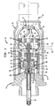
- Further objects of this invention, as well as the novel features thereof, will become apparent by reference to the following description, taken in conjunction with the accompanying figure, the same being an axial, cross-sectional view of the invention according to an embodiment thereof.
- The novel, electrical,
switching mechanism 10, has acylindrical shell 12 which is threaded at the left-hand end where a correspondingly threadedmounting header 14 is threadedly engaged. At the opposite, right-hand end of theshell 12, anend adapter 16 is joined by weld. Theadapter 16 receives anelectrical connector 18. Within theshell 12, theconnector 18 haswiring terminals 20. Welded to an inner face of theheader 14 is an open-ended cylinder 22. The remote, open end of thecylinder 22 is internally threaded and has a threadedplatform 24 engaged therewith. Theplatform 24 mounts a pair ofelectrical contacts 26 therein, the latter being fixed in place, in parallel, ininsulating sleeves 28. Inwardly -projecting, terminal ends of thecontacts 26 lie in a plane "A", and the outwardly -extending portions thereof are joined towires 30. - Intermediate the length of the
cylinder 22 is an inner threaded,annular portion 32. Another threadedplatform 34 is threadedly joined toportion 32, and mounts a second pair ofelectrical contacts 36. Adjacent to threaded,annular portion 32, thecylinder 22 has a pair ofapertures 38 through whichfurther wires 40 penetrate and are electrically bound to thecontacts 36.Contacts 36, too, are fixed in place, inplatform 34 in additionalinsulating sleeves 28. Terminal ends of thecontacts 36, which confront the terminal ends ofcontacts 26, lie in a plane "B". -
Header 14 mounts, centrally therein, aconduit 42 for admitting a fluid medium therethrough and into thecylinder 22.Platform 34 has a threaded,central bore 44, and threaded thereinto is theshank 46 of asupport 48. Support 48, and itsshank 46, have athroughgoing bore 50 formed therein, and slidably receives therein ashaft 52 of an elongate,contact disc assembly 54. At the left-hand end ofshaft 52 there is mounted a piston head 56. The latter is disposed in immediate adjacency to the innermost end ofconduit 42. Fixed to the inner face of theheader 14, to isolate the piston head 56 from admitted fluid medium, is adiaphragm 58. - Set within the inner or left-hand end of the
cylinder 22 is acarriage 60. The same comprises an outer, internally threadedsleeve 62, an innermost, annular,belleville spring retainer 64, a cup-shaped, centrally-bored, and externally threadedabutment member 66. Interpositioned between, and threadedly engaged with,member 66 andsleeve 62, is a dual-walled,annular element 68 which nests therein the outer periphery of abelleville spring 70. The inner periphery of thespring 70 is nested in a groove provided therefor in thesupport 48. Asecond belleville spring 72 has its outer periphery nested inretainer 64, and its inner periphery set about a reduced diameter portion of piston head 56. -
Contact disc assembly 54 has, at its right-hand end, adisc holder 74. The latter is threadedly coupled to the correspondingly threaded end ofshaft 52, and has anannular insulation piece 76 thereat. An electrically-conductingdisc 78 is mounted upon theinsulation piece 76, and as shown lies along plane "B" in electrically-contacting or shunting engagement with thecontacts 36. Consequently,disc 78 completes a circuit throughwires 40 andcontacts 36. This is the normal or quiescent state of themechanism 10. - Belleville
spring 72 is outwardly biased, as shown, to hold the piston head 56 against thediaphragm 58 and inner face of theheader 14 with a given preload. Upon a pressured fluid medium having greater force than such preload being introduced into the housing, i.e.,shell 12 andcylinder 22, behind thediaphragm 58, via theconduit 42, thespring 72 snaps inwardly, instantly to move thecontact disc assembly 54 to the right. As a result of this, the piston head 56 meets the abutment presented byabutment member 66, and theshunting disc 78 withdraws from plane "B" and the terminal ends ofcontacts 36. At this time, thebelleville spring 70 is stressed, but does not yield to the pressure; it has a higher preload than hasspring 72. Thecarriage 60, then, which is only slidably disposed in thecylinder 22, remains in place, held byspring 70. - If the pressure of the fluid medium is diminished, or the medium itself is evacuated, the
spring 72 returns to its normal, preloaded disposition, and snaps thecontact disc assembly 54 back to the normal, quiescent state, as shown in the figure, with thedisc 78 in shunting engagement with thecontacts 36. - If the pressure of the fluid medium is increased, beyond the preload of
belleville spring 70, then this spring yields and, with a snap action, carries thecarriage 60 rightward until the inner, annular end ofsleeve 62 meets the abutment presented byplatform 34, and thecontact disc assembly 54 moves along therewith. Now, in this circumstance, thedisc 78 occupies plane "A" and is in shunting engagement with thecontacts 26. - Again, if the pressure of the fluid medium is diminished to a level between the threshold at which it causes the
spring 70 to yield, and the threshold at which it causes thespring 72 to yield,spring 70 will snap back to its normal attitude, and retract thecarriage 60.Spring 72 however will still be flexed, as the assumed pressure level will not permit it to relax. Consequently, thedisc 78 will be between planes "A" and "B", and will retrain thereat until the pressure of the fluid medium diminishes to the below threshold level at whichspring 72 can snap back to its relaxed attitude. - It is to be noted that when the
carriage 60 is snapped to the right, by the yielding ofspring 70, it carries the abutment ofabutment member 66 therewith. As a consequence, with the concomitant flexing ofspring 72, the piston head 56 can translate further into theshell 22. This is how it is that thedisc 78 succeeds to plane "A" and shunting contact withcontacts 26. - The
contacts shunting disc 78, in the manner described in the forgoing, makes positive, instant contacting engagement therewith. No normal vibration, shock or the like, can cause themechanism 10 to switch faultingly, or erringly disengage from contact. Themechanism 10 switches two electrical circuits at two different fluid medium pressures; hence, themechanism 10 is useful for dual set point requirements: alarm and shutdown, or warning and shutdown, etc. It offers accuracy, repeatability and reliability not found in prior art dual set point switches or switching mechanisms. Themechanism 10 lends itself to infinite adjustment, for differing, selected pressures or set points, in that theshank 46 of thesupport 48 is axially adjustable in theplatform 34, thedisc holder 74 is threadedly adjustable on theshaft 52,platform 34 is axially adjustable within thecylinder 22 atportion 32, the threadedabutment member 66 is adjustable withinannular element 68, and the latter is adjustable, axially, within thesleeve 62. - While I have described my invention in connection with a specific embodiment thereof, it is to be clearly understood that this is done only by way of example, and not as a limitation to the scope of the invention as set forth in the objects thereof and in the appended claims. For instance, herein pressured fluid medium is set forth as the motive force. Clearly, a liquid could be admitted via the
conduit 42, a liquid which is heated giving rise to a pressure escalation thereof which moves thediaphragm 58 and displaces the piston head 56 as a consequence thereof. Therefore the mechanism would be temperature-actuated in the same manner as described herein for a pressured fluid medium admitted via theconduit 42.
Claims (12)
- An electrical switching mechanism comprising:
a housing (12), wherein said housing has means for admitting a pressured fluidum thereinto; a first pair of electrical contacts (26), mounted within said housing having terminal ends thereof lying in a first plane (A), characterized in that a second pair of electrical contacts (36) are mounted within said housing having terminal ends thereof lying in a second plane (B), a shunting, contact disc (78), movably disposed within said housing (12) being interposed between said first and second pairs of contacts and that means (72) are confined within said housing (a) for constraining said disc in one (A) of said planes in normal engagement with said ends of one of said pairs of contacts (26), and (b) for instantly, with snap action, displacing said disc (78) from said engagement and said one plane, in response to admittance of fluid medium at a first threshold of pressure, and for instantly, with snap action, moving said disc (78) to the other (B) of said planes and into engagement with said ends of said other pair of contacts (36), in response to admittance of fluid medium at a second threshold of pressure. - An electrical switching mechanism according to claim 1, characterized in that a carriage (60) is movably disposed in said housing (12), the latter being provided with an abutment (66) for delimiting movement of said carriage, that an elongate, contact disc assembly (54) is movable disposed within said carriage (60), that said assembly is provided with piston means (56) at one end thereof, and disposed in immediate adjacency to said medium admitting means (42), for moving said assembly in response to an admittance of fluid medium into said housing (12), that said carriage (60) has an abutment (66) thereon for delimiting movement of said assembly (54) therewithin, that first means (72) are confined in said housing and engaged with said assembly for (a) constraining said disc (78) in contact with one of said first (26) and second (36) pairs of contacts and (b) restraining said assembly against movements thereof relative said carriage (60), and that second means (70) are disposed within said housing and engaged with said carriage (60) for restraining said carriage against movement thereof relative to said housing (12).
- An electrical switching mechanism, according to claim 2, characterized in that said abutment (66) within said carriage has an aperture formed therein, centrally thereof; and further including a support (48), mounted in said aperture; wherein said support has a throughgoing bore formed therein; and said assembly (54) is slidably engaged with said bore.
- An electrical switching mechanism, according to claim 2, characterized in that it includes a support (48) mounted to said abutment (66) within said housing; on which said second means (70) is mounted.
- An electrical switching mechanism, according to claim 2, characterized in that said first means (72), is interposed between said piston means (56) and said carriage (60).
- An electrical switching mechanism, according to claim 2, characterized in that one of said first and second means comprises a belleville spring (70).
- An electrical switching mechanism, according to claim 2, characterized in that said first and second means comprise belleville springs (70, 72).
- An electrical switching mechanism, according to claim 1, characterized in that said abutment (66) within said housing comprises means for supporting one (36) of said pairs of electrical contacts within said housing.
- An electrical switching mechanism, according to claim 2, characterized in that it includes means (58) interposed between said housing and said piston means (56) for isolating said piston means from fluid medium admitted via said admitting means (42).
- An electrical switching mechanism, according to claim 9, characterized in that said isolating means comprises a diaphragm (58).
- An electrical switching mechanism, according to claim 2, characterized in that said housing carriage (60) is internally threaded; and that said abutment (66) within said carriage is externally threaded, and adjustably threadedly engaged with such carriage internal threads.
- An electrical switching mechanism, according to claim 3, characterized in that said aperture is threaded; that said support (48) has an externally threaded shank (46); and that said shank is threadedly engaged with said aperture.
Applications Claiming Priority (2)
| Application Number | Priority Date | Filing Date | Title |
|---|---|---|---|
| US876647 | 1992-04-30 | ||
| US07/876,647 US5233142A (en) | 1992-04-30 | 1992-04-30 | Snap action electrical switching mechanism with dual set points |
Publications (3)
| Publication Number | Publication Date |
|---|---|
| EP0567719A2 EP0567719A2 (en) | 1993-11-03 |
| EP0567719A3 EP0567719A3 (en) | 1994-01-26 |
| EP0567719B1 true EP0567719B1 (en) | 1997-01-29 |
Family
ID=25368262
Family Applications (1)
| Application Number | Title | Priority Date | Filing Date |
|---|---|---|---|
| EP92850268A Expired - Lifetime EP0567719B1 (en) | 1992-04-30 | 1992-11-13 | Electrical switching mechanism |
Country Status (3)
| Country | Link |
|---|---|
| US (1) | US5233142A (en) |
| EP (1) | EP0567719B1 (en) |
| DE (1) | DE69217202T2 (en) |
Families Citing this family (3)
| Publication number | Priority date | Publication date | Assignee | Title |
|---|---|---|---|---|
| US5538185A (en) * | 1992-05-29 | 1996-07-23 | Rabitsch; Benjamin F. | Vehicle mounted liquid spray apparatus |
| US5469978A (en) * | 1994-07-12 | 1995-11-28 | Keystone Railway Equipment Company, Inc. | Condition indicating system for railway car cushioning unit |
| DE19847614A1 (en) * | 1998-10-15 | 2000-05-04 | Magenwirth Gmbh Co Gustav | Snap switch |
Family Cites Families (8)
| Publication number | Priority date | Publication date | Assignee | Title |
|---|---|---|---|---|
| US3668347A (en) * | 1970-01-19 | 1972-06-06 | Robertshaw Controls Co | Snap acting electrical switch construction having reset means |
| US3876845A (en) * | 1973-11-16 | 1975-04-08 | Neo Dyn Inc | Pressure and temperature actuated switches |
| US4225760A (en) * | 1978-05-30 | 1980-09-30 | International Telephone And Telegraph Corporation | Pressure actuated unit with high temperature protection |
| US4757165A (en) * | 1986-12-23 | 1988-07-12 | Texas Instruments Incorporated | Dual condition responsive electrical switch |
| JPH07114094B2 (en) * | 1987-07-23 | 1995-12-06 | 株式会社不二工機製作所 | Three-action pressure switch |
| US4794214A (en) * | 1987-10-28 | 1988-12-27 | Texas Instruments Incorporated | Fluid pressure responsive electrical switch |
| US4820890A (en) * | 1987-12-09 | 1989-04-11 | Fuji Koki Mfg. Co. Ltd. | Three-function pressure switch |
| US5004873A (en) * | 1989-09-20 | 1991-04-02 | Eaton Corporation | Plural set point pressure responsive switching apparatus utilizing a single pressure sensing driver element |
-
1992
- 1992-04-30 US US07/876,647 patent/US5233142A/en not_active Expired - Fee Related
- 1992-11-13 DE DE69217202T patent/DE69217202T2/en not_active Expired - Lifetime
- 1992-11-13 EP EP92850268A patent/EP0567719B1/en not_active Expired - Lifetime
Also Published As
| Publication number | Publication date |
|---|---|
| EP0567719A3 (en) | 1994-01-26 |
| US5233142A (en) | 1993-08-03 |
| DE69217202T2 (en) | 1997-07-17 |
| EP0567719A2 (en) | 1993-11-03 |
| DE69217202D1 (en) | 1997-03-13 |
Similar Documents
| Publication | Publication Date | Title |
|---|---|---|
| US4642603A (en) | Brake rod extension indicator | |
| JPH02500473A (en) | Pressure detection type electric pressure switch | |
| US2803718A (en) | Pressure controlled device | |
| EP0567719B1 (en) | Electrical switching mechanism | |
| US4892985A (en) | Vacuum responsive multicontact switch | |
| US2275556A (en) | Switch | |
| US3364321A (en) | Condition sensing and controlling switch device | |
| US5508483A (en) | High pressure switch apparatus | |
| US3848517A (en) | Pressure sensitive device for operating a switch or the like | |
| US4168415A (en) | Pressure switch having modular construction | |
| JPH07260602A (en) | Sensor | |
| US2902557A (en) | Pressure-responsive switches | |
| US3330925A (en) | Snap-acting pressure switch | |
| US3746810A (en) | Pressure operated electric switches with flexible helical bridging contact | |
| US4493957A (en) | Multimodal pressure switch | |
| US4048455A (en) | Pressure switch with plural axes pivoted conduction plate | |
| US2418222A (en) | Overtravel switch actuator | |
| US2640896A (en) | Thermostat device | |
| US4238651A (en) | Snap action fluid pressure switch | |
| US3706133A (en) | Electrical switches | |
| US3319024A (en) | Pressure responsive electric switches | |
| CA1253544A (en) | Multimodal pressure switch | |
| US4392608A (en) | Thermally responsive fluid and electrical switch and control system | |
| US3774138A (en) | Temperature responsive switch | |
| US3340371A (en) | Switch device for pressure cylinders |
Legal Events
| Date | Code | Title | Description |
|---|---|---|---|
| PUAI | Public reference made under article 153(3) epc to a published international application that has entered the european phase |
Free format text: ORIGINAL CODE: 0009012 |
|
| AK | Designated contracting states |
Kind code of ref document: A2 Designated state(s): DE FR GB |
|
| PUAL | Search report despatched |
Free format text: ORIGINAL CODE: 0009013 |
|
| AK | Designated contracting states |
Kind code of ref document: A3 Designated state(s): DE FR GB |
|
| 17P | Request for examination filed |
Effective date: 19940712 |
|
| 17Q | First examination report despatched |
Effective date: 19960108 |
|
| GRAG | Despatch of communication of intention to grant |
Free format text: ORIGINAL CODE: EPIDOS AGRA |
|
| GRAH | Despatch of communication of intention to grant a patent |
Free format text: ORIGINAL CODE: EPIDOS IGRA |
|
| GRAH | Despatch of communication of intention to grant a patent |
Free format text: ORIGINAL CODE: EPIDOS IGRA |
|
| GRAA | (expected) grant |
Free format text: ORIGINAL CODE: 0009210 |
|
| AK | Designated contracting states |
Kind code of ref document: B1 Designated state(s): DE FR GB |
|
| REF | Corresponds to: |
Ref document number: 69217202 Country of ref document: DE Date of ref document: 19970313 |
|
| ET | Fr: translation filed | ||
| PLBE | No opposition filed within time limit |
Free format text: ORIGINAL CODE: 0009261 |
|
| STAA | Information on the status of an ep patent application or granted ep patent |
Free format text: STATUS: NO OPPOSITION FILED WITHIN TIME LIMIT |
|
| 26N | No opposition filed | ||
| REG | Reference to a national code |
Ref country code: GB Ref legal event code: IF02 |
|
| PGFP | Annual fee paid to national office [announced via postgrant information from national office to epo] |
Ref country code: DE Payment date: 20101126 Year of fee payment: 19 |
|
| PGFP | Annual fee paid to national office [announced via postgrant information from national office to epo] |
Ref country code: GB Payment date: 20101124 Year of fee payment: 19 |
|
| PGFP | Annual fee paid to national office [announced via postgrant information from national office to epo] |
Ref country code: FR Payment date: 20111128 Year of fee payment: 20 |
|
| REG | Reference to a national code |
Ref country code: DE Ref legal event code: R071 Ref document number: 69217202 Country of ref document: DE |
|
| REG | Reference to a national code |
Ref country code: DE Ref legal event code: R071 Ref document number: 69217202 Country of ref document: DE |
|
| REG | Reference to a national code |
Ref country code: GB Ref legal event code: PE20 Expiry date: 20121112 |
|
| PG25 | Lapsed in a contracting state [announced via postgrant information from national office to epo] |
Ref country code: GB Free format text: LAPSE BECAUSE OF EXPIRATION OF PROTECTION Effective date: 20121112 |