EP0567290B1 - Frame assembly for carrying electrical signals and the like - Google Patents
Frame assembly for carrying electrical signals and the like Download PDFInfo
- Publication number
- EP0567290B1 EP0567290B1 EP93303041A EP93303041A EP0567290B1 EP 0567290 B1 EP0567290 B1 EP 0567290B1 EP 93303041 A EP93303041 A EP 93303041A EP 93303041 A EP93303041 A EP 93303041A EP 0567290 B1 EP0567290 B1 EP 0567290B1
- Authority
- EP
- European Patent Office
- Prior art keywords
- frame
- conductors
- pultrusion
- frame assembly
- machine
- Prior art date
- Legal status (The legal status is an assumption and is not a legal conclusion. Google has not performed a legal analysis and makes no representation as to the accuracy of the status listed.)
- Expired - Lifetime
Links
Images






Classifications
-
- H—ELECTRICITY
- H05—ELECTRIC TECHNIQUES NOT OTHERWISE PROVIDED FOR
- H05K—PRINTED CIRCUITS; CASINGS OR CONSTRUCTIONAL DETAILS OF ELECTRIC APPARATUS; MANUFACTURE OF ASSEMBLAGES OF ELECTRICAL COMPONENTS
- H05K7/00—Constructional details common to different types of electric apparatus
- H05K7/18—Construction of rack or frame
- H05K7/183—Construction of rack or frame support rails therefor
-
- H—ELECTRICITY
- H02—GENERATION; CONVERSION OR DISTRIBUTION OF ELECTRIC POWER
- H02B—BOARDS, SUBSTATIONS OR SWITCHING ARRANGEMENTS FOR THE SUPPLY OR DISTRIBUTION OF ELECTRIC POWER
- H02B1/00—Frameworks, boards, panels, desks, casings; Details of substations or switching arrangements
- H02B1/01—Frameworks
-
- H—ELECTRICITY
- H02—GENERATION; CONVERSION OR DISTRIBUTION OF ELECTRIC POWER
- H02B—BOARDS, SUBSTATIONS OR SWITCHING ARRANGEMENTS FOR THE SUPPLY OR DISTRIBUTION OF ELECTRIC POWER
- H02B1/00—Frameworks, boards, panels, desks, casings; Details of substations or switching arrangements
- H02B1/20—Bus-bar or other wiring layouts, e.g. in cubicles, in switchyards
- H02B1/202—Cable lay-outs
-
- H—ELECTRICITY
- H02—GENERATION; CONVERSION OR DISTRIBUTION OF ELECTRIC POWER
- H02B—BOARDS, SUBSTATIONS OR SWITCHING ARRANGEMENTS FOR THE SUPPLY OR DISTRIBUTION OF ELECTRIC POWER
- H02B1/00—Frameworks, boards, panels, desks, casings; Details of substations or switching arrangements
- H02B1/01—Frameworks
- H02B1/013—Profiles for cabinet frames
-
- H—ELECTRICITY
- H02—GENERATION; CONVERSION OR DISTRIBUTION OF ELECTRIC POWER
- H02B—BOARDS, SUBSTATIONS OR SWITCHING ARRANGEMENTS FOR THE SUPPLY OR DISTRIBUTION OF ELECTRIC POWER
- H02B1/00—Frameworks, boards, panels, desks, casings; Details of substations or switching arrangements
- H02B1/01—Frameworks
- H02B1/014—Corner connections for frameworks
Definitions
- This invention relates to improvements in structural frame members and assemblies, and more particularly to improvements in frame members and assemblies for use in conjunction with machines requiring electrical circuit interconnections, and still more particularly to improvements in frame members and assemblies of the type which are capable of conducting electrical signals, voltages, and the like, to and from the circuitry of an associated machine.
- a photoconductive insulating surface often in the form of a moving belt, is uniformly charged and exposed to a light image from an original document.
- the light image causes the exposed or background areas to become discharged, and creates an electrostatic latent image on the surface corresponding to the image contained within the original document.
- a light beam such as a laser beam may be modulated and used to selectively discharge portions of the photoconductive surface to record the desired information thereon.
- the electrostatic latent image is made visible by developing the image with a developer powder, referred to in the art as toner, which may be subsequently transferred to a support surface such as paper to which it may be permanently affixed by the application of heat and/or pressure.
- New manufacturing processes are likely to be required for efficient and economical patterning, plating, and component loading of the large multifunctional parts envisioned for copiers of the future. Also required will be new materials and methods to construct key structural members.
- US-A-4,689,726 to Kretzschmar discloses a lighting system for an adjustable shelf system.
- the lighting system comprises a fixture laterally extending along a shelf, the shelf being adjustably positionable along a combination electrical conductor and shelf positioner.
- the fixture includes an electrically conductive strip.
- US-A-4,997,240 to Schmalzl et al. discloses a modular housing system for electronic equipment.
- the housing system consists of capping pieces of extruded sections provided with keyhole shaped guide grooves in a longitudinal direction that are modularly joined with corner nodes and connector elements adaptable for respective utilization.
- US-A-5,003,741 to Yen discloses a structure of multi-function frame members.
- a tubular member of octagonal shape is provided on its outer sides with dovetail slots and on its inside with opposed longitudinal engaging surfaces.
- a connector is in the form of a support with orthogonally disposed legs that can be received in the octagonal tube.
- a frame may be made up from a number of the tubes and connectors and numerous other fittings may be provided which fit in the dovetail slots.
- US-A-3,973,371 to Heller discloses an apparatus and system for constructing a skeletal framework out of extruded aluminum members adapted to support wall, furniture or other structural panels.
- the apparatus includes a plurality of elongated channel members, each having a generally rectangular cross section, one side which defines an axial slot. A cover for this side is also provided which when put together with the channel member gives a complete skeletal frame member.
- a plurality of spline members are provided to interconnect the frame members at their ends.
- the recesses provided by the structural framework support structural panels to provide an interior wall or furniture piece.
- US-A-4,187,649 to Chaffee discloses a frame construction adapted for the use in framing panels and forming parallelepiped configurations.
- the frame is constructed out of a metallic material and is comprised of tubular frame members and corner connectors.
- US-A-4,931,326 to Weil discloses a reinforced flexible plastic tubing and method of manufacture.
- the tubing is a composite tubular device comprising a flexible, hollow, plastic tube and a flexible, hollow, tubular, porous member at least substantially embedded in the plastic tube.
- the tubular member should both have an outer and an inner side as well as macroscopic pores substantially uniformly distributed around and along the tubular member.
- the plastic of the tube is extended through a multiplicity of the pores between the inner and outer sides of the tubular member.
- EP-A-428,055 discloses a conductor rail (10) comprising a support structure (13), an insulator (11) and a conductor or condutors (12).
- the supporting structure (13) and the insulator (11) of the conductor rail (19) are formed into one and the same uniform profile by means of a pultrusion method.
- US-A-4,795,355 discloses a movable panel member incorporating an integrated electrical current distributing busbar.
- the panel member comprises a channel member forming a current duct in which there is inserted a current distributing busbar, and a communication duct, separated by a partition, for accommodating communication cables.
- a frame assembly comprising: a frame member for providing mechanical support, and for carrying electrical conduction paths for connection to circuitry of a machine, the frame member including a pultrusion including an insulating body and reinforcing fibers within said insulating body, and conductors on surface portions of said pultrusion, said conductors providing electrical conduction paths connectable to circuitry of said machine; and at least one contact block, said contact block being attachable to at least one of said frame members and having conductor contacting portions for contacting at least some of said conductors when said contact block is attached to said at least one frame member.
- the invention enables a frame assembly to be constructed from a number of similar frame members of the type described, for use in carrying a machine or machine components.
- the invention enables fully automated frame assembly construction, including the installation of Integrated Input Output Connector (llOC) modules and other interconnecting connectors.
- llOC Integrated Input Output Connector
- Such a frame assembly reduces wiring harness requirements, particularly in reprographic copy machines.
- a frame member of the type described is of extremely high reliability, due to the extent of integration possible and use of auto assembly processes.
- the frame member and frame assembly including it can have AC conductors located on interior surfaces of the structure, reducing shorting and safety hazards as well as providing ready access for module mounting and interconnection.
- the electrical buss/wires may be provided that are interconnected to the llOC module to derive its function.
- Other DC signals may be provided on the frame members.
- a frame member and frame assembly may be provided in which frame member joining modules can be provided with programming capabilities to create unique llOC networks.
- a frame member for affording mechanical support, and for carrying electrical conduction paths for connection to circuitry of a machine.
- the frame member is comprised of a pultrusion having an insulating resin binder and reinforcing fibers within the insulating resin binder.
- the pultrusion has grooves in surface portions along an elongated dimension with conductors in the grooves.
- the conductors provide electrical conduction paths that are connectable to circuitry of the machine.
- the pultrusion may be a thermal setting polymer, for example, selected from the group consisting essentially of polyester, vinyl ester, and epoxies, and, preferably, may be reinforced with fiberglass.
- the reinforcing fibers can be conductive fibers, such as conductive carbon fibers, metalized carbon fibers, or the like, that may be contained in the pultrusion aligned perpendicularly to the elongated dimension, and in one embodiment, additionally can be arranged in planes substantially perpendicular to the elongated dimension.
- the frame member in one embodiment, has a hollow interior portion within which conductors can be arranged to conduct AC power to the circuitry of the machine, and the conductors on the exterior surface of the frame member can be arranged to conduct llOC bus signals and low voltage power.
- the frame member in another embodiment, includes a semi-cylindrically shaped member formed by the pultrusion that serves as a corner member on an external periphery of the machine.
- the corner member can be aesthetically colored and textured, and arranged to secure an external machine cover.
- a plurality of the frame members are provided with grooves and conductors corresponding ones of which can be interconnected to facilitate supplying and directing the electrical signals to the machine.
- the connections can be made to and among the electrical conductors carried by the pultrusions by blocks that are attachable to the pultrusions, in one embodiment of "T" shape.
- a frame assembly for use in machine constructions, in general, and reprographic copy machine constructions, in particular.
- the frame assembly is formed of pultruded frame members interconnected by joining members of various shapes or configurations.
- the individual frame members are pultruded composites, such as those routinely manufactured by commercial vendor sources such as the MMFG Company of Bristol Virginia as linear shapes that use continuous filament reinforcement.
- Such pultruded composites are easily capable of achieving mechanical properties that can match, or in many cases, exceed those of most metals.
- pultrusions are fabricated from a thermal setting polymer matrix, such as a polyester, a vinyl ester or an epoxy resin, formulated to meet specific chemical, flame retardant, electrical, and environmental requirements, containing, at least one type of fiber reinforcement filler, such as fiberglass, polyester fiber, carbon fiber, and ceramic fiber being among those most widely used.
- a thermal setting polymer matrix such as a polyester, a vinyl ester or an epoxy resin
- fiber reinforcement filler such as fiberglass, polyester fiber, carbon fiber, and ceramic fiber being among those most widely used.
- Individual conductive traces provided on one, or more, surfaces of the pultruded frame members for selective interconnection with the conductive traces of other pultruded frame members comprise the circuitry of the machine with which the frame is associated to interconnect signals or voltages, or the like.
- the pultrusions by which the frame members are formed can be of pultruded square, or rectangular, or any other suitably shaped tubular, straight, or right angle, configured sections, and may include molded corner, "T", and spline sections to join the pultruded members into solid frame structures.
- the frame members can also be attached to each other or the joining members through the use of adhesives, ultrasonics, heat fusing, or other securing techniques suitable to the materials being joined.
- multiple power and logic circuits can be incorporated within or upon the surfaces of the pultruded sections, and, if desired, a means to place through-hole interconnects in the walls of the pultrusions can be provided to enable IIOC's and other input/Output (I/O) connectors to be connected to the signal/power runs.
- I/O input/Output
- the frame member can assume various embodiments, such as those characterized by any of a number of cross sectional shapes, and provisions such as grooves or the like can be made, if desired as shown, to provide conductor paths along virtually any surface of the pultrusion, for instance, on interior surfaces, as shown in Figures 1a and 1b, exterior surfaces, as shown in Figure 1d, or both interior and exterior surfaces, as below described.
- the lengths of the frame members can be 3 or more metres long if desired, to carry thin (for example of thickness between about 0.05 to 1.25 mm) conductor strips, such as of copper foil co-pultruded together, or alternately adhesively joined together with the polymer matrix to form the desired configuration.
- the widths of the conductor strips can be adjusted, for instance, to form wider power buses or narrower signal traces.
- Figure 1c illustrates an embodiment wherein an array of, for example, eight conductor strips are provided on an exterior surface.
- the conductor strips can be approximately 1.8 mm wide, the conductor strips having approximately 0.75 mm wide insulator strips provided therebetween.
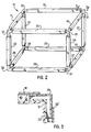
- One frame assembly embodiment 15 in accordance with the invention is shown in Figure 2, and is constructed with pultruded frame members 17 - 28 carrying circuit bus and power conductors (not shown) running continuously along the periphery of at least one surface of the structure. Corner joining members 30 - 37 mechanically interconnect the pultruded frame members 17 - 28, and also establish electrical connections between selected ones of the circuit bus and power conductors carried on the pultruded frame members. Interior corner encoder 101 as illustrated in Figure 6a is selectively connected to external conductors to create desired nets.
- FIG. 3 An enlarged view of a corner connection, taken at section 3-3 in Figure 2 is shown in Figure 3, illustrating an arrangement in which circuit paths 38 and 38' are located on the inner walls 40 and 41 of the respective pultruded frame members 18 and 22 to be interconnected by a conductor 39 on the outer walls of the corner section 31.
- the corner member 31 has a good interference fit, but nevertheless may be secured in a permanent position by adhesive, or thermal bonding, or by ultrasonic welding of the plastic and/or metal members or by screws or other appropriate fasteners (not shown)
- the Conductors shown can be joined by soldering, snap fits, conventional welding, ultrasonic welding or other suitable electrical joining techniques.
- connections may be established to the conductors of the pultruded frame members 18 - 27 or the various corner connectors 30 - 37 at virtually any desired location along their lengths to facilitate conduction of the desired selected signals or voltages to the various machine parts which may be carried within or by the frame assembly 15.
- connections can be established by connection blocks, screws, pins, or other means, depending upon the particular embodiment employed.
- the circuit bus and power conductors can be of any suitable electrically conducting material, such as copper or other suitable metal plated or otherwise formed on the desired surfaces of the pultrusions as described above.
- the frame members can be formed through known techniques for forming electrically conductive paths in a polymer matrix which is filled with electrically insulating fibers that are capable of heat conversion to electrically conducting fibers. By such technique, by selectively heating the filled polymer matrix the electrically conductive paths can be formed in situ in selected regions of the individual frame members 17 - 28.
- Such a technique may be performed, for example, by providing an electrically insulating polymer matrix which will form a frame member, loaded or doped with a suitable polymeric fibrous material capable of heat conversion to conductive fibrous carbon within the polymer matrix.
- suitable fibrous filler are cellulose (rayon), petroleum pitch based carbon fibers which are heat convertible carbonaceous fibers, and thermally stabilized, polyacrylonitrile fibers.
- the fiber filled polymer matrix doped with such fibers can be formed into the desired frame member configuration by conventional injection molding, extrusion, or pultrusion techniques, then selectively heated, preferably by a laser such as a carbon dioxide laser, to convert the electrically insulating fibrous filler to an electrically conductive filler along the desired paths.
- a laser such as a carbon dioxide laser
- a number of similarly constructed pultruded frame members can be provided, each contributing a substantially identical "building block” that can easily and selectively be interconnected to adjoining building blocks.
- FIGs 4 and Sa One configuration for such building block frame members and frame assemblies formed therewith is shown in Figures 4 and Sa.
- the pultruded frame member 50 is of generally square or rectangular shape, having a similarly shaped square or rectangular core 51 with enclosed inner surfaces 53 and exposed outer surfaces 54.
- Square corner members 56 are provided as shown to enable physical connections to be made to the frame member 50, such as by screws, or the like, affixed to standard hole patterns created in the frames.
- the holes can also be used to mount mechanical sub-systems, provide screw holes for the joining and programming modules (described below), and for mounting signal bus or other connectors.
- the matrix of the pultruded frame member 50 contains continuous fiber strands to resist stresses of tension, compression, and bending of the part, plus, continuous strand mat to reinforce surfaces and prevent lineal splitting and chipping from impact.
- one or more filament winding processes is employed to provide for fiber rich inner and outer layers where a portion of the continuous fiber reinforcement 58 in these layers is aligned perpendicular to an elongated dimension of the frame member 50.
- the square corner member 56 carries reinforcing continuous fibers 59, predominantly oriented lengthwise along the elongated dimension of the pultruded frame member 50.
- the reinforcing fibers 59 can be conductive fibers, for example, conductive carbon fibers, metalized carbon fibers, or the like.
- not all of the fibers should be conductive. Preferably, however, at least 5% by weight of the fibers should be conductive fibers. Further, the use of carbon is effective in building stiffer frame structures than frame structures obtained, for example, by using fiberglass alone.
- three conductors 60, 61, and 62 are provided on one of the inner surfaces 53 of the frame member 50 to serve as power conductors for the AC bus, and five conductors 70 - 74 are provided in grooves on three of the outer sides 54 of the frame member 50 to provide a signal bus, such as an llOC bus.
- a signal bus such as an llOC bus.
- the pultruded frame member 50 provides a basic building block from which a machine frame having a convenient wiring configuration can easily be assembled by interconnecting several of the building block frame elements.
- three frame members 50 I , 50 II and 50 III of similar construction to the frame member 50 described above are provided for interconnection at a "T" junction.
- a "T" shaped molded corner section 84 is constructed by conventional insert molding techniques, and is provided having copper circuit runs 88 configured to mate with the AC power conductors 60-62 in the interior of the individual frame members 50 I -50 III when the legs of the "T" shaped member 84 are inserted into their interior portions.
- Rails 89 are attached to the body of the "T" shaped molded corner section 84 to contact the mating corner members 56 of respective ones of the pultruded frame members 50 I , 50 II , and 50 III , and, if desired, the rails 89 may be provided with interior continuous reinforcement fibers (not shown).
- the reinforcing fibers can be conductive fibers, for example, conductive carbon fibers, metalized carbon fibers, or the like to electrically contact the fibers 59 within the corner members 56, for example to establish a ground or noise isolation capability within the frame members 50.
- the conductors 70-74 on the outer surfaces of the members 50 I -50 III are interconnected by one or more "T" shaped connector 90.
- the "T” shaped connector 90 has a number of conductors or wires 92 mounted onto a block 93, in turn carried by a "T" bracket or backing plate 94.
- the components of the "T" shaped member 90 are of such dimensions that when the backing plate 90 is attached to the corner members 56 and rails 89, such as by screws 95 or the like, the block 93 brings the conductors 92 into contact with respective ones of the conductors 70-74 on the outside surfaces 54 of the pultruded frame members 50 I , 50 II , and 50 III .
- programming of bus routing can be accomplished by drilling or punching out various selected ones of the conductors 92 prior to attachment of the "T" shaped connector 90; therefore, the "T" shaped connector 90 serves not only physical and electrical interconnection functions, but enables programming of bus routing as well.
- FIGSb illustrates another embodiment of a "T" interconnection module assembly for use in conjunction with the present invention.
- a "T” connector 84' has legs 150 which are inserted into interior portions of frame members.
- the "T” connector 84' has bolts 152 extending through legs 150. Wedges 154 in the frame members mate with bolts 152.
- conductors of the frame members are soldered all around within each leg 150 of "T" connector 84'.
- Figure 5c illustrates a "T” connector 84" for use in conjunction with the present invention.
- the "T” connector 84" includes a molded conductor pattern 158 mounted therein.
- Conductor pattern 158 enables "T” connector 84" to serve as both a physical and electrical interconnection.
- Figure Sd illustrates a "T” connector 84"' wherein molded conductor pattern 158 is insert molded in glass 160.
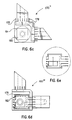
- FIG. 6a A corner construction for a frame assembly, in accordance with a preferred embodiment of the invention, for the interconnection of three pultrusion frame member building blocks 50 IV , 50 V , and 50 VI is shown in Figure 6a.
- the corner connection shown in Figure 6a is similar to the "T" connection described above with reference to Figure 5b, except for the differently configured base corner 100 and connection bracket 101.
- FIG. 6b illustrates another embodiment of a corner module assembly for use in conjunction with the present invention.
- Corner module 100' is similar to "T" connector 84'.
- Corner module 100' has legs 170 which are inserted into interior portions of frame members.
- Corner module 100' has bolts 172 extending through legs 170. Wedges 174 in the frame members mate with bolts 172.
- conductors of the frame members are soldered all around within each leg 170 of corner module 100'.
- FIG. 6c illustrates a corner module 100" for use in conjunction with the present invention.
- Corner module 100" includes a molded conductor pattern 178 mounted therein.
- An exploded view of member 180 illustrates a vertical conductor pattern within member 180.
- Figure 6d illustrates a corner module 100"' wherein molded conductor pattern 178 is insert molded in glass 182.
- Addition of llOC or other connectors can be accomplished at almost any position of the frame members, as illustrated in Figure 8. As shown, for example, connections may be made to any arbitrary location along the elongated dimension of a pultruded frame member 50 Y by various special purposes connectors. Connectors to drawer sub-systems can be made by a drawer connector 120, to frame mounted components by multiple pin terminals 126 of an llOC module 121, to sub-systems connected requiring wire bus connections by a bus connector 122, and so on. Power connections can be made by a power bus connector 123.
- circuit buses are located on inner wall surfaces
- laser or mechanical drilling techniques can be used to produce through holes, such as through holes 125 on frame member 50 Y , to locate and connect the connectors to the runs.
- the AC circuit buses can be located on the outer, accessible surfaces (not shown) for surface or snap mount connections directly onto the runs at appropriate locations.
- spring type contacts are provided on the surfaces of the connector blocks facing the frame member 50 Y .
- the spring contacts are located so that when the connector blocks 120-122 are fastened to the frame member 50 Y , such as by screws 128, or other fastening means, the spring contacts are brought into electrical connection with respective desired conductors of the frame member 50 Y .
- the frame members in accordance with preferred embodiments of the invention enable full automation of frame assemblies, including installation of llOC modules and interconnecting connectors, and results in frame assemblies which have extremely high reliability due to the large extent of integration possible and use of automatic assembly processes which are enabled.
- AC conductors can be run on the interior surfaces of the structure with ground included, thereby preventing shorting and reducing safety hazards, as well as providing ready access for module mounting and interconnection to the inner conductors, for example, with a screw, or the like
- the joining and programming modules impart final mechanical strength, enabling programming by drilling or punching out selected buses to create unique llOC nets as illustrated in Figure 12.
- a pultruded frame member 135 of rectangular shaped cross-section suitable for use as a "Smart Frame” member is shown in Figure 9.
- another pultruded frame member configuration 138 which can be employed is shown in Figure 10.
- the configuration 138 of Figure 10 provides a corner 140 that can be used to engage machine enclosing panels 141, as shown in Figure 11, in which panels or sliding covers 141 are received and secured by members 138 I , 138 II , and 138 III , by screws 143, or other fastening means.
- Color, texture, and other aesthetic features can also be provided within members 138 by the pultrusion process.
- Figure 12 illustrates a "Smart Frame” Nets diagram in accordance with the present invention.
- insert molded connections are selectively connected to pultrusions, thus creating “Nets” having differing electrical functions.
- the “Nets” are created in the case of both “T” and corner connections.
- An electrical “Net” is defined as several segments of an electrically conductive surface joined together at the same electrical potential.
- a “Net” is formed by selectively connecting the insert molded features of the corners and tees with the desired frame member.
Landscapes
- Engineering & Computer Science (AREA)
- Power Engineering (AREA)
- Microelectronics & Electronic Packaging (AREA)
- Electrophotography Configuration And Component (AREA)
- Casings For Electric Apparatus (AREA)
Description
- This invention relates to improvements in structural frame members and assemblies, and more particularly to improvements in frame members and assemblies for use in conjunction with machines requiring electrical circuit interconnections, and still more particularly to improvements in frame members and assemblies of the type which are capable of conducting electrical signals, voltages, and the like, to and from the circuitry of an associated machine.
- Although the invention has wide applications, as will become apparent, a preferred embodiment of the invention is particularly suitable for applications in electrostatographic reproducing machines. In a typical electrostatographic reproducing machine, a photoconductive insulating surface, often in the form of a moving belt, is uniformly charged and exposed to a light image from an original document. The light image causes the exposed or background areas to become discharged, and creates an electrostatic latent image on the surface corresponding to the image contained within the original document. Alternatively, a light beam such as a laser beam may be modulated and used to selectively discharge portions of the photoconductive surface to record the desired information thereon. The electrostatic latent image is made visible by developing the image with a developer powder, referred to in the art as toner, which may be subsequently transferred to a support surface such as paper to which it may be permanently affixed by the application of heat and/or pressure.
- In these commercial applications, it is of course necessary to distribute electrical power, high voltage and/or logic signals between the various units, subsystems, customer replaceable units and/or cartridges of the machine. Traditionally, this has been accomplished utilizing conventional wires and wiring harnesses in each machine to distribute power and logic signals between, for example, the main processor and frame of the machine and a removable processing unit. For instance, conventional plug and socket arrangements have been used which can be either manually connected or joined automatically on insertion of the unit into the main processor. Such automatic joining requires precision positioning and alignment of the unit on insertion with very low tolerance for error. Typically locating members such as pins or rails are used to insure proper positioning, all of which adds to the manufacturing cost of the machine. In addition, conventional wires and wiring harnesses are flexible and therefore, do not lend themselves to automated assembly such as with the use of conventional robots further leading to increased manufacturing costs.
- In many typical copier systems, flexible interconnects have been accomplished by such techniques as flexible ribbon wires with plugs that attach to mating plugs on the members to be interconnected. Such ribbon wiring arrangements, however, do not lend physical support between the interconnected members, and also often involve intensive labor fabrication requirements. Furthermore, such harnesses may have to be handled or moved several times to make all connections required. This is a highly labor intensive task, frequently requiring routing of the several harnesses through channels and around components manually with the final connections being also accomplished manually, thereby resulting in potential human error in the assembly, which might be reduced with the use of automated and in particular robotic assembly. Conventional harnesses also often require chafe protection, standoffs, and tie wraps which further add to the assembly and installation costs. In addition to the relatively high labor costs associated with electrical harness construction and installation, it is well to note that such wiring harnesses are less than totally reliable in producing their intended function. Furthermore, and with increasing sophistication of the capabilities of such products, a plurality of wiring harnesses may be required in any individual machine which can require a large volume of space thereby increasing the overall size of the machine. Accordingly, there is a desire to provide an alternative to the conventional wiring and wiring harnesses that overcomes these difficulties.
- One of the considerations for the development of wiring harnesses and interconnects in electrostatic copier environments is the relatively hostile machine surroundings having surfaces possibly contaminated by dirt, toner, silicone oil, or other debris. Furthermore, metal contacts that might be used often tend to oxidize forming an insulating layer on the contact surface thereby further degrading the reliability and performance of the contact and of the machine. Such contacts, therefore, need to be either improved or minimized.
- To address these and other problems, and with recent emphasis toward the goal of replacing conventional wire harnesses in copier products to achieve a so-called "wireless copier", what is needed is the incorporation of circuit functions directly into large structural machine parts. For example, the surfaces of machine covers, frames housings, support brackets, bases, and the like, can all provide vacant "real estate" for circuitization, given that the substrate materials are, or can be made, insulating and can be appropriately "circuitized ".
- New manufacturing processes are likely to be required for efficient and economical patterning, plating, and component loading of the large multifunctional parts envisioned for copiers of the future. Also required will be new materials and methods to construct key structural members.
- What is needed is the identification of new materials and fabrication techniques by which structural frames having integrated electrical interconnect features can be provided.
- US-A-4,689,726 to Kretzschmar discloses a lighting system for an adjustable shelf system. The lighting system comprises a fixture laterally extending along a shelf, the shelf being adjustably positionable along a combination electrical conductor and shelf positioner. The fixture includes an electrically conductive strip. By use of this design, no wiring is needed within the structure of the bookshelf.
- US-A-4,997,240 to Schmalzl et al. discloses a modular housing system for electronic equipment. The housing system consists of capping pieces of extruded sections provided with keyhole shaped guide grooves in a longitudinal direction that are modularly joined with corner nodes and connector elements adaptable for respective utilization.
- US-A-5,003,741 to Yen discloses a structure of multi-function frame members. A tubular member of octagonal shape is provided on its outer sides with dovetail slots and on its inside with opposed longitudinal engaging surfaces. A connector is in the form of a support with orthogonally disposed legs that can be received in the octagonal tube. A frame may be made up from a number of the tubes and connectors and numerous other fittings may be provided which fit in the dovetail slots.
- US-A-4,912,288 and 5,003,693, both to Atkinson et al., disclose methods of providing an electrical circuit molded within a three-dimensional plastic substrate by the application of heat and pressure.
- US-A-4,841,099 and 4,970,533, to Epstein et al. and Orlowski et al., respectively, and both assigned to the assignee of the present invention, disclose a three-dimensional electrical component made from an electrically insulating polymer matrix which is capable of heat conversion to electrically conductive fibrous filler to provide a conductive trace on the component. A structural frame of a copier is shown having electroconductive paths.
- US-A-3,973,371 to Heller discloses an apparatus and system for constructing a skeletal framework out of extruded aluminum members adapted to support wall, furniture or other structural panels. The apparatus includes a plurality of elongated channel members, each having a generally rectangular cross section, one side which defines an axial slot. A cover for this side is also provided which when put together with the channel member gives a complete skeletal frame member. A plurality of spline members are provided to interconnect the frame members at their ends. The recesses provided by the structural framework support structural panels to provide an interior wall or furniture piece.
- US-A-4,187,649 to Chaffee discloses a frame construction adapted for the use in framing panels and forming parallelepiped configurations. The frame is constructed out of a metallic material and is comprised of tubular frame members and corner connectors.
- US-A-4,931,326 to Weil discloses a reinforced flexible plastic tubing and method of manufacture. The tubing is a composite tubular device comprising a flexible, hollow, plastic tube and a flexible, hollow, tubular, porous member at least substantially embedded in the plastic tube. The tubular member should both have an outer and an inner side as well as macroscopic pores substantially uniformly distributed around and along the tubular member. Before the member is incorporated into the composite tubular device, the plastic of the tube is extended through a multiplicity of the pores between the inner and outer sides of the tubular member.
- EP-A-428,055 discloses a conductor rail (10) comprising a support structure (13), an insulator (11) and a conductor or condutors (12). The supporting structure (13) and the insulator (11) of the conductor rail (19) are formed into one and the same uniform profile by means of a pultrusion method.
- US-A-4,795,355 discloses a movable panel member incorporating an integrated electrical current distributing busbar. The panel member comprises a channel member forming a current duct in which there is inserted a current distributing busbar, and a communication duct, separated by a partition, for accommodating communication cables.
- It is an object of the invention to provide a frame member for affording mechanical support and for carrying electrical conduction paths for connection to circuitry of a machine.
- According to the present invention as defined in claim 1, there is provided a frame assembly, comprising: a frame member for providing mechanical support, and for carrying electrical conduction paths for connection to circuitry of a machine, the frame member including a pultrusion including an insulating body and reinforcing fibers within said insulating body, and conductors on surface portions of said pultrusion, said conductors providing electrical conduction paths connectable to circuitry of said machine; and at least one contact block, said contact block being attachable to at least one of said frame members and having conductor contacting portions for contacting at least some of said conductors when said contact block is attached to said at least one frame member.
- The invention enables a frame assembly to be constructed from a number of similar frame members of the type described, for use in carrying a machine or machine components.
- The invention enables fully automated frame assembly construction, including the installation of Integrated Input Output Connector (llOC) modules and other interconnecting connectors.
- Such a frame assembly reduces wiring harness requirements, particularly in reprographic copy machines.
- A frame member of the type described is of extremely high reliability, due to the extent of integration possible and use of auto assembly processes.
- The frame member and frame assembly including it can have AC conductors located on interior surfaces of the structure, reducing shorting and safety hazards as well as providing ready access for module mounting and interconnection.
- The electrical buss/wires (net) may be provided that are interconnected to the llOC module to derive its function. Other DC signals may be provided on the frame members.
- A frame member and frame assembly may be provided in which frame member joining modules can be provided with programming capabilities to create unique llOC networks.
- By virtue of the present invention, new materials and fabrication techniques which result in structural frames having integrated electrical interconnect features can be provided. More particularly, a "Smart Frame" concept is disclosed which can be used as the basis for comprehension of, as well as for the construction of a commercially viable "wireless copier" architecture for mid and high volume copiers and other electrical and electronic products. By means of such "Smart Frame" concepts, integration of electronic functions into traditional machine frame members can be easily realized by which additional layers of multifunctionality of the frame members are enabled by the various frame member configurations described below.
- Thus, a frame member is provided for affording mechanical support, and for carrying electrical conduction paths for connection to circuitry of a machine. The frame member is comprised of a pultrusion having an insulating resin binder and reinforcing fibers within the insulating resin binder. The pultrusion has grooves in surface portions along an elongated dimension with conductors in the grooves. The conductors provide electrical conduction paths that are connectable to circuitry of the machine. The pultrusion may be a thermal setting polymer, for example, selected from the group consisting essentially of polyester, vinyl ester, and epoxies, and, preferably, may be reinforced with fiberglass.
- The reinforcing fibers can be conductive fibers, such as conductive carbon fibers, metalized carbon fibers, or the like, that may be contained in the pultrusion aligned perpendicularly to the elongated dimension, and in one embodiment, additionally can be arranged in planes substantially perpendicular to the elongated dimension.
- The frame member, in one embodiment, has a hollow interior portion within which conductors can be arranged to conduct AC power to the circuitry of the machine, and the conductors on the exterior surface of the frame member can be arranged to conduct llOC bus signals and low voltage power.
- The frame member, in another embodiment, includes a semi-cylindrically shaped member formed by the pultrusion that serves as a corner member on an external periphery of the machine. The corner member can be aesthetically colored and textured, and arranged to secure an external machine cover.
- A plurality of the frame members, in accordance with still another embodiment of the invention, are provided with grooves and conductors corresponding ones of which can be interconnected to facilitate supplying and directing the electrical signals to the machine. The connections can be made to and among the electrical conductors carried by the pultrusions by blocks that are attachable to the pultrusions, in one embodiment of "T" shape.
- The invention is illustrated in the accompanying drawings, in which:
- Figures la - le are cross sectional. views of various pultrusion shapes which are exemplary of shapes suitable for practicing the invention;
- Figure 2 is an isometric view of a machine frame having interconnected pultrusion elements, in accordance with a preferred embodiment of the invention;
- Figure 3 is a cross sectional view of a corner connection of the machine frame, taken at 3-3 in Figure 2;
- Figure 4 is a top view of a pultruded frame member, in accordance with a preferred embodiment of the invention;
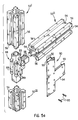
- Figure 5a is an exploded isometric view of a first embodiment of a "T" interconnection of three pultruded frame members of the type shown in Figure 4;
- Figure 5b is a view of a second embodiment of a "T" interconnection module assembly;
- Figures 5c and 5d are two views of the second embodiment of the "T" interconnection in accordance with the present invention referenced in Figure 5b;
- Figure 6a is an exploded isometric view of a first embodiment of a corner interconnection of three pultruded frame members of the type shown in Figure 4;
- Figure 6b is a view of another embodiment of a corner module assembly;
- Figures 6c and 6d are two views of the second embodiment of corner modules used in accordance with the present invention referenced in Figure 6b;
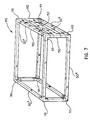
- Figure 7 is an isometric view of a completed frame assembly using a number of pultruded frame members of Figure 4 and "T" and corner interconnections of Figures 5 and 6;
- Figure 8 is an isometric view of a frame member with various connectors which can be used to establish electrical contact to the various conductors of the frame member;
- Figure 9 is an isometric view of a pultruded frame member having a single electrical bus array in accordance with another preferred embodiment of the invention;
- Figures 10 and 11 are top diagrammatic views of another pultruded frame member of configuration suitable for presenting decorative features for use in external or publicly visible portions of a frame assembly as well as for providing securing capabilities for machine enclosing panels or the like; and
- Figure 12 is an isometric view of a "Smart Frame" nets diagram showing some possible combinations of nets routing utilizing the conductors that are fabricated on the frame member of Figure 4.
- In the various figures of the drawings, the sizes and dimensions of the parts are not necessarily to scale and have been exaggerated or distorted in some instances for clarity of illustration and ease of description. In addition, in the various figures, like reference numerals are used to denote like or similar parts.
- Although the invention in its broad aspect has many applications, in accordance with one aspect of the present invention a frame assembly is provided for use in machine constructions, in general, and reprographic copy machine constructions, in particular. The frame assembly is formed of pultruded frame members interconnected by joining members of various shapes or configurations. Still more particularly, the individual frame members are pultruded composites, such as those routinely manufactured by commercial vendor sources such as the MMFG Company of Bristol Virginia as linear shapes that use continuous filament reinforcement. Such pultruded composites are easily capable of achieving mechanical properties that can match, or in many cases, exceed those of most metals. Usually, pultrusions are fabricated from a thermal setting polymer matrix, such as a polyester, a vinyl ester or an epoxy resin, formulated to meet specific chemical, flame retardant, electrical, and environmental requirements, containing, at least one type of fiber reinforcement filler, such as fiberglass, polyester fiber, carbon fiber, and ceramic fiber being among those most widely used. Individual conductive traces provided on one, or more, surfaces of the pultruded frame members for selective interconnection with the conductive traces of other pultruded frame members, comprise the circuitry of the machine with which the frame is associated to interconnect signals or voltages, or the like.
- The pultrusions by which the frame members are formed can be of pultruded square, or rectangular, or any other suitably shaped tubular, straight, or right angle, configured sections, and may include molded corner, "T", and spline sections to join the pultruded members into solid frame structures. The frame members can also be attached to each other or the joining members through the use of adhesives, ultrasonics, heat fusing, or other securing techniques suitable to the materials being joined. Moreover, multiple power and logic circuits can be incorporated within or upon the surfaces of the pultruded sections, and, if desired, a means to place through-hole interconnects in the walls of the pultrusions can be provided to enable IIOC's and other input/Output (I/O) connectors to be connected to the signal/power runs.
- For example, as shown in Figures la - le, the frame member can assume various embodiments, such as those characterized by any of a number of cross sectional shapes, and provisions such as grooves or the like can be made, if desired as shown, to provide conductor paths along virtually any surface of the pultrusion, for instance, on interior surfaces, as shown in Figures 1a and 1b, exterior surfaces, as shown in Figure 1d, or both interior and exterior surfaces, as below described. The lengths of the frame members can be 3 or more metres long if desired, to carry thin (for example of thickness between about 0.05 to 1.25 mm) conductor strips, such as of copper foil co-pultruded together, or alternately adhesively joined together with the polymer matrix to form the desired configuration. The widths of the conductor strips can be adjusted, for instance, to form wider power buses or narrower signal traces.
- Figure 1c illustrates an embodiment wherein an array of, for example, eight conductor strips are provided on an exterior surface. In this embodiment, the conductor strips can be approximately 1.8 mm wide, the conductor strips having approximately 0.75 mm wide insulator strips provided therebetween.
- One
frame assembly embodiment 15 in accordance with the invention is shown in Figure 2, and is constructed with pultruded frame members 17 - 28 carrying circuit bus and power conductors (not shown) running continuously along the periphery of at least one surface of the structure. Corner joining members 30 - 37 mechanically interconnect the pultruded frame members 17 - 28, and also establish electrical connections between selected ones of the circuit bus and power conductors carried on the pultruded frame members.Interior corner encoder 101 as illustrated in Figure 6a is selectively connected to external conductors to create desired nets. An enlarged view of a corner connection, taken at section 3-3 in Figure 2 is shown in Figure 3, illustrating an arrangement in whichcircuit paths 38 and 38' are located on theinner walls pultruded frame members conductor 39 on the outer walls of thecorner section 31. Thecorner member 31 has a good interference fit, but nevertheless may be secured in a permanent position by adhesive, or thermal bonding, or by ultrasonic welding of the plastic and/or metal members or by screws or other appropriate fasteners (not shown) The Conductors shown can be joined by soldering, snap fits, conventional welding, ultrasonic welding or other suitable electrical joining techniques. - As described below in detail, connections may be established to the conductors of the pultruded frame members 18 - 27 or the various corner connectors 30 - 37 at virtually any desired location along their lengths to facilitate conduction of the desired selected signals or voltages to the various machine parts which may be carried within or by the
frame assembly 15. As will become apparent, such connections can be established by connection blocks, screws, pins, or other means, depending upon the particular embodiment employed. - In the embodiment illustrated, the circuit bus and power conductors can be of any suitable electrically conducting material, such as copper or other suitable metal plated or otherwise formed on the desired surfaces of the pultrusions as described above. Alternatively, the frame members can be formed through known techniques for forming electrically conductive paths in a polymer matrix which is filled with electrically insulating fibers that are capable of heat conversion to electrically conducting fibers. By such technique, by selectively heating the filled polymer matrix the electrically conductive paths can be formed in situ in selected regions of the individual frame members 17 - 28.
- Such a technique may be performed, for example, by providing an electrically insulating polymer matrix which will form a frame member, loaded or doped with a suitable polymeric fibrous material capable of heat conversion to conductive fibrous carbon within the polymer matrix. Examples of suitable fibrous filler are cellulose (rayon), petroleum pitch based carbon fibers which are heat convertible carbonaceous fibers, and thermally stabilized, polyacrylonitrile fibers. The fiber filled polymer matrix doped with such fibers can be formed into the desired frame member configuration by conventional injection molding, extrusion, or pultrusion techniques, then selectively heated, preferably by a laser such as a carbon dioxide laser, to convert the electrically insulating fibrous filler to an electrically conductive filler along the desired paths. Thus, directing the laser beam onto the selected portions of the polymer matrix to be pyrolyzed results in melting the polymer and heat converting the electrically insulating fibers to electrically conductive fibers to form the required conductive paths.
- In accordance with a preferred embodiment of the invention, a number of similarly constructed pultruded frame members can be provided, each contributing a substantially identical "building block" that can easily and selectively be interconnected to adjoining building blocks. One configuration for such building block frame members and frame assemblies formed therewith is shown in Figures 4 and Sa. As can be seen from the details of the end view of a typical
pultruded frame member 50 shown in Figure 4, thepultruded frame member 50 is of generally square or rectangular shape, having a similarly shaped square orrectangular core 51 with enclosedinner surfaces 53 and exposedouter surfaces 54.Square corner members 56 are provided as shown to enable physical connections to be made to theframe member 50, such as by screws, or the like, affixed to standard hole patterns created in the frames. The holes can also be used to mount mechanical sub-systems, provide screw holes for the joining and programming modules (described below), and for mounting signal bus or other connectors. - The matrix of the
pultruded frame member 50 contains continuous fiber strands to resist stresses of tension, compression, and bending of the part, plus, continuous strand mat to reinforce surfaces and prevent lineal splitting and chipping from impact. In the embodiment illustrated, one or more filament winding processes is employed to provide for fiber rich inner and outer layers where a portion of thecontinuous fiber reinforcement 58 in these layers is aligned perpendicular to an elongated dimension of theframe member 50. Moreover, thesquare corner member 56 carries reinforcingcontinuous fibers 59, predominantly oriented lengthwise along the elongated dimension of thepultruded frame member 50. The reinforcingfibers 59 can be conductive fibers, for example, conductive carbon fibers, metalized carbon fibers, or the like. In order to prevent shorting of electrical runs from occurring, not all of the fibers should be conductive. Preferably, however, at least 5% by weight of the fibers should be conductive fibers. Further, the use of carbon is effective in building stiffer frame structures than frame structures obtained, for example, by using fiberglass alone. - As shown, three
conductors inner surfaces 53 of theframe member 50 to serve as power conductors for the AC bus, and five conductors 70 - 74 are provided in grooves on three of theouter sides 54 of theframe member 50 to provide a signal bus, such as an llOC bus. It should, of course, be noted that although three redundant sets of bus conductors are provided on three sides of theframe member 50 to enable convenient routing and connection of the bus conductors, the conductors on each of the three sides can be provided for separate or independent functions as may be desired. - As mentioned, the
pultruded frame member 50, constructed as described above, provides a basic building block from which a machine frame having a convenient wiring configuration can easily be assembled by interconnecting several of the building block frame elements. Thus, as shown in Figure 5a, threeframe members frame member 50 described above are provided for interconnection at a "T" junction. A "T" shaped moldedcorner section 84 is constructed by conventional insert molding techniques, and is provided having copper circuit runs 88 configured to mate with the AC power conductors 60-62 in the interior of the individual frame members 50I-50III when the legs of the "T" shapedmember 84 are inserted into their interior portions.Rails 89 are attached to the body of the "T" shaped moldedcorner section 84 to contact themating corner members 56 of respective ones of thepultruded frame members rails 89 may be provided with interior continuous reinforcement fibers (not shown). The reinforcing fibers can be conductive fibers, for example, conductive carbon fibers, metalized carbon fibers, or the like to electrically contact thefibers 59 within thecorner members 56, for example to establish a ground or noise isolation capability within theframe members 50. - The conductors 70-74 on the outer surfaces of the members 50I-50III are interconnected by one or more "T" shaped
connector 90. The "T" shapedconnector 90 has a number of conductors orwires 92 mounted onto ablock 93, in turn carried by a "T" bracket or backingplate 94. The components of the "T" shapedmember 90 are of such dimensions that when thebacking plate 90 is attached to thecorner members 56 and rails 89, such as byscrews 95 or the like, theblock 93 brings theconductors 92 into contact with respective ones of the conductors 70-74 on the outside surfaces 54 of thepultruded frame members conductors 92 prior to attachment of the "T" shapedconnector 90; therefore, the "T" shapedconnector 90 serves not only physical and electrical interconnection functions, but enables programming of bus routing as well. - Figure Sb illustrates another embodiment of a "T" interconnection module assembly for use in conjunction with the present invention. A "T" connector 84' has
legs 150 which are inserted into interior portions of frame members. The "T" connector 84' hasbolts 152 extending throughlegs 150.Wedges 154 in the frame members mate withbolts 152. As illustrated byreference numeral 156, in the Figure 5b embodiment, conductors of the frame members are soldered all around within eachleg 150 of "T" connector 84'. - Figure 5c illustrates a "T"
connector 84" for use in conjunction with the present invention. The "T"connector 84" includes a moldedconductor pattern 158 mounted therein.Conductor pattern 158 enables "T"connector 84" to serve as both a physical and electrical interconnection. Figure Sd illustrates a "T"connector 84"' wherein moldedconductor pattern 158 is insert molded inglass 160. - A corner construction for a frame assembly, in accordance with a preferred embodiment of the invention, for the interconnection of three pultrusion frame
member building blocks base corner 100 andconnection bracket 101. - Figure 6b illustrates another embodiment of a corner module assembly for use in conjunction with the present invention. Corner module 100' is similar to "T" connector 84'. Corner module 100' has
legs 170 which are inserted into interior portions of frame members. Corner module 100' hasbolts 172 extending throughlegs 170.Wedges 174 in the frame members mate withbolts 172. As illustrated by reference numeral 176, in the Figure 6b embodiment, conductors of the frame members are soldered all around within eachleg 170 of corner module 100'. - Figure 6c illustrates a
corner module 100" for use in conjunction with the present invention.Corner module 100" includes a moldedconductor pattern 178 mounted therein. An exploded view ofmember 180 illustrates a vertical conductor pattern withinmember 180. Figure 6d illustrates acorner module 100"' wherein moldedconductor pattern 178 is insert molded inglass 182. - By provision of the corner and "T" sections described, the construction of a complete machine frame, such as the
frame 110 shown in Figure 7 can be envisioned by joining appropriate lengths ofbuilding blocks 50X together atcorner junctions 111 and "T"junctions 112. - Addition of llOC or other connectors can be accomplished at almost any position of the frame members, as illustrated in Figure 8. As shown, for example, connections may be made to any arbitrary location along the elongated dimension of a
pultruded frame member 50Y by various special purposes connectors. Connectors to drawer sub-systems can be made by adrawer connector 120, to frame mounted components bymultiple pin terminals 126 of anllOC module 121, to sub-systems connected requiring wire bus connections by abus connector 122, and so on. Power connections can be made by apower bus connector 123. For locations where the circuit buses are located on inner wall surfaces, laser or mechanical drilling techniques can be used to produce through holes, such as throughholes 125 onframe member 50Y, to locate and connect the connectors to the runs. Alternatively, the AC circuit buses can be located on the outer, accessible surfaces (not shown) for surface or snap mount connections directly onto the runs at appropriate locations. - To enable the various connector blocks 120-122 to establish connections to the conductors 70-74 on the outside surfaces 54 of the
frame member 50Y, preferably spring type contacts (not shown) are provided on the surfaces of the connector blocks facing theframe member 50Y. The spring contacts are located so that when the connector blocks 120-122 are fastened to theframe member 50Y, such as byscrews 128, or other fastening means, the spring contacts are brought into electrical connection with respective desired conductors of theframe member 50Y. - It can be seen that the frame members, in accordance with preferred embodiments of the invention enable full automation of frame assemblies, including installation of llOC modules and interconnecting connectors, and results in frame assemblies which have extremely high reliability due to the large extent of integration possible and use of automatic assembly processes which are enabled. AC conductors can be run on the interior surfaces of the structure with ground included, thereby preventing shorting and reducing safety hazards, as well as providing ready access for module mounting and interconnection to the inner conductors, for example, with a screw, or the like The joining and programming modules impart final mechanical strength, enabling programming by drilling or punching out selected buses to create unique llOC nets as illustrated in Figure 12.
- The manufacturing of composite plastic frame parts as described above by pultrusion processes lends itself readily to the formation of non-traditional and highly featured structures For example, a
pultruded frame member 135 of rectangular shaped cross-section suitable for use as a "Smart Frame" member is shown in Figure 9. Additionally, another pultrudedframe member configuration 138 which can be employed is shown in Figure 10. Theconfiguration 138 of Figure 10 provides acorner 140 that can be used to engagemachine enclosing panels 141, as shown in Figure 11, in which panels or slidingcovers 141 are received and secured bymembers screws 143, or other fastening means. Color, texture, and other aesthetic features can also be provided withinmembers 138 by the pultrusion process. - Figure 12 illustrates a "Smart Frame" Nets diagram in accordance with the present invention. In this figure, insert molded connections are selectively connected to pultrusions, thus creating "Nets" having differing electrical functions. The "Nets" are created in the case of both "T" and corner connections. An electrical "Net" is defined as several segments of an electrically conductive surface joined together at the same electrical potential. A "Net" is formed by selectively connecting the insert molded features of the corners and tees with the desired frame member.
Claims (8)
- A frame assembly, comprising:a frame member for providing mechanical support, and for carrying electrical conduction paths for connection to circuitry of a machine, the frame member including a pultrusion (17-28, 50, 135, 138) including an insulating body (51,56) and reinforcing fibers (59) within said insulating body, and conductors (70-74) on surface portions of said pultrusion, said conductors providing electrical conduction paths connectable to circuitry of said machine; andat least one contact block (30-37, 84, 100, 111, 112), said contact block being attachable to at least one of said frame members and having conductor contacting portions for contacting at least some of said conductors when said contact block is attached to said at least one frame member.
- The frame assembly of claim 1 wherein said pultrusion is a thermal setting polymer selected from polyesters, vinyl esters, and epoxies.
- The frame assembly of claim 1 or claim 2 wherein said pultrusion (50) has a hollow interior portion (53) extending along the direction of an elongated dimension of said pultrusion.
- The frame assembly of claim 3 including conductors (60-62) located within said hollow interior portion of said pultrusion.
- The frame assembly of any one of claims 1 to 4 further comprising a longitudinally extending member (140) carried by said pultrusion (138), said member serving as a corner member on an external periphery of the machine, and adapted to secure an external machine cover (141).
- The frame assembly of any one of claims 1 to 5 wherein said pultrusion has grooves in surface portions along an elongated dimension.
- The frame assembly of claim 6 including a plurality of conductors in said grooves.
- A frame assembly of any of the preceding claims wherein said plurality of conductors of one of said frame members connect to a respective plurality of conductors of another of said frame members when said one and said another of said frame members are connected together.
Applications Claiming Priority (2)
| Application Number | Priority Date | Filing Date | Title |
|---|---|---|---|
| US07/871,163 US5298681A (en) | 1992-04-20 | 1992-04-20 | Frame member and assembly for carrying electrical signals and the like |
| US871163 | 1992-04-20 |
Publications (2)
| Publication Number | Publication Date |
|---|---|
| EP0567290A1 EP0567290A1 (en) | 1993-10-27 |
| EP0567290B1 true EP0567290B1 (en) | 1997-01-22 |
Family
ID=25356851
Family Applications (1)
| Application Number | Title | Priority Date | Filing Date |
|---|---|---|---|
| EP93303041A Expired - Lifetime EP0567290B1 (en) | 1992-04-20 | 1993-04-20 | Frame assembly for carrying electrical signals and the like |
Country Status (4)
| Country | Link |
|---|---|
| US (1) | US5298681A (en) |
| EP (1) | EP0567290B1 (en) |
| JP (1) | JP3536986B2 (en) |
| DE (1) | DE69307580T2 (en) |
Cited By (1)
| Publication number | Priority date | Publication date | Assignee | Title |
|---|---|---|---|---|
| US11505899B2 (en) | 2018-12-05 | 2022-11-22 | Nvent Services Gmbh | Anti-icing surface with polymeric supports |
Families Citing this family (48)
| Publication number | Priority date | Publication date | Assignee | Title |
|---|---|---|---|---|
| JP2693906B2 (en) * | 1993-12-03 | 1997-12-24 | 日本電気エンジニアリング株式会社 | Communication device mounting frame |
| US5474460A (en) * | 1994-08-23 | 1995-12-12 | Emc Corporation | Power interconnect system for electronic assemblies |
| US5899025A (en) * | 1996-03-22 | 1999-05-04 | Steelcase Inc. | Furniture system (pathways-spaceframe) |
| US5897400A (en) * | 1997-06-30 | 1999-04-27 | Digital Equipment Corporation | Tower building block system |
| US6024476A (en) * | 1998-04-21 | 2000-02-15 | Us Sign And Fabrication Corporation | Optical fiber lighting of channel letters |
| FR2783642B1 (en) * | 1998-09-21 | 2000-12-01 | Schneider Electric Sa | METAL STRUCTURE WITH ELECTRICAL CONNECTION PIECE |
| US7245291B2 (en) | 2000-07-11 | 2007-07-17 | Imran Sharif | System and method for internet appliance data entry and navigation |
| US20020078445A1 (en) * | 2000-07-11 | 2002-06-20 | Imran Sharif | Internet appliance for interactive audio/video display using a remote control unit for user input |
| US6980313B2 (en) * | 2000-07-11 | 2005-12-27 | Imran Sharif | Fax-compatible internet appliance |
| US20030115167A1 (en) * | 2000-07-11 | 2003-06-19 | Imran Sharif | Web browser implemented in an Internet appliance |
| US6722471B2 (en) * | 2000-12-22 | 2004-04-20 | Albert A. Wolfe | Scaffolding system having improved safety structures and connecting members |
| ITMI20010505A1 (en) * | 2001-03-09 | 2002-09-09 | Abb Ricerca Spa | JUNCTION DEVICE AND EARTHING OF COMPONENTS OF A FRAME FOR AN ELECTRIC PANEL CABINET |
| US6481582B1 (en) * | 2001-06-04 | 2002-11-19 | Cooper Technologies Company | Rack |
| US7194513B2 (en) * | 2001-07-08 | 2007-03-20 | Imran Sharif | System and method for using an internet appliance to send/receive digital content files as E-mail attachments |
| US7034227B2 (en) * | 2002-08-19 | 2006-04-25 | Fox Ron W | Cable trough |
| US7007431B2 (en) * | 2003-05-09 | 2006-03-07 | Nci Building Systems, Lp | Multi-story building and method for construction thereof |
| US20060059790A1 (en) * | 2004-08-31 | 2006-03-23 | Yeung Hubert K | Systems and methods for modular instrument design and fabrication |
| US20110036966A1 (en) * | 2006-06-12 | 2011-02-17 | Bryan Benedict | Stay-in-Place Concrete Footing Forms |
| WO2008117462A1 (en) * | 2007-03-27 | 2008-10-02 | Fujitsu Limited | Electronic device with keyboard |
| WO2008117461A1 (en) * | 2007-03-27 | 2008-10-02 | Fujitsu Limited | Electronic device and frame therefor |
| US7518060B1 (en) | 2007-05-31 | 2009-04-14 | Comfort Line, Ltd. | Prefabricated structural member having a wire routing system |
| US8099859B2 (en) * | 2007-09-24 | 2012-01-24 | Malm Robert E | Modular assembly |
| US20100175919A1 (en) * | 2009-01-14 | 2010-07-15 | Boston Retail Products, Inc. | System and method for distribution of electrical power |
| EP2270287A1 (en) * | 2009-06-29 | 2011-01-05 | Rockwool International A/S | A building assembly with a corner profile for an insulating building system |
| US8439333B2 (en) | 2010-05-25 | 2013-05-14 | Caldwell Tanks, Inc. | Removable misting array assembly for an abatement system |
| US8870166B2 (en) | 2010-05-25 | 2014-10-28 | Caldwell Tanks, Inc. | Misting array assembly of an abatement system |
| CN102316697A (en) * | 2010-07-09 | 2012-01-11 | 鸿富锦精密工业(深圳)有限公司 | Machine cabinet frame |
| KR101201740B1 (en) * | 2010-11-12 | 2012-11-15 | 에스비리모티브 주식회사 | Battery module |
| US8772650B2 (en) * | 2011-01-10 | 2014-07-08 | Apple Inc. | Systems and methods for coupling sections of an electronic device |
| JP5559135B2 (en) * | 2011-12-22 | 2014-07-23 | タキゲン製造株式会社 | Equipment storage rack |
| FR2995464B1 (en) * | 2012-09-08 | 2021-05-14 | Cqfd Composites | BEAM CONTAINING ELECTRICAL CONDUCTORS AND ELECTRIFICATION SYSTEM USING SUCH BEAMS |
| WO2014047874A1 (en) * | 2012-09-28 | 2014-04-03 | 中联重科股份有限公司 | Proportional steering valve, proportional steering hydraulic circuit, proportional steering system and vehicle |
| US9200658B2 (en) * | 2013-08-29 | 2015-12-01 | Paul R. Gerst | Gusset |
| US10201110B1 (en) * | 2014-02-19 | 2019-02-05 | Lockheed Martin Corporation | Device rack incorporating multiple mounting planes |
| CN104953472A (en) * | 2015-05-27 | 2015-09-30 | 国家电网公司 | Novel combined heat-insulating moisture-proof box |
| US10213026B2 (en) | 2015-08-24 | 2019-02-26 | L&P Property Management Company | Pultruded adjustable bed frame |
| GB2550920A (en) * | 2016-05-31 | 2017-12-06 | Bombardier Transp Gmbh | Cubicle and rail vehicle comprising a cubicle |
| WO2018081415A1 (en) | 2016-10-27 | 2018-05-03 | Steelcase Inc. | Flip top table |
| CN108551063B (en) * | 2018-05-31 | 2024-03-26 | 企鹅创新(北京)科技有限公司 | Detachable conductive track of carbon fiber |
| US10745901B2 (en) * | 2018-11-21 | 2020-08-18 | Steel Worx Solutions LLC | System and method of constructing a multi-story building utilizing modular components |
| US11164146B2 (en) | 2019-11-12 | 2021-11-02 | Dell Products L.P. | Inventory identification |
| US11582874B2 (en) | 2020-01-15 | 2023-02-14 | Dell Products L.P. | Interlocking transportation totes |
| US11388836B2 (en) * | 2020-01-15 | 2022-07-12 | Dell Products L.P. | Plastic tote |
| CN212623545U (en) * | 2020-08-28 | 2021-02-26 | 中强光电股份有限公司 | Frame Modules and Projection Units |
| DE202022105380U1 (en) | 2022-09-26 | 2022-10-31 | Megger Germany Gmbh | Measuring device arrangement for functional testing of electrical lines and vehicle with measuring device arrangement |
| AT18097U1 (en) * | 2022-09-26 | 2024-01-15 | Megger Germany Gmbh | Measuring device arrangement for functional testing of electrical cables and vehicle with measuring device arrangement |
| DE202023100716U1 (en) | 2023-02-15 | 2023-04-04 | Megger Germany Gmbh | Installation frame for the detachable attachment of a measuring device arrangement in a vehicle |
| USD1067019S1 (en) * | 2024-03-18 | 2025-03-18 | Xing Luo | Cabinet column |
Citations (2)
| Publication number | Priority date | Publication date | Assignee | Title |
|---|---|---|---|---|
| US4795355A (en) * | 1986-08-23 | 1989-01-03 | E C O Gmbh Elektric Concept For Offices Produktion + Marketing | Movable panel member incorporating an integrated electrical current distributing busbar |
| EP0428055A2 (en) * | 1989-11-15 | 1991-05-22 | Neste Oy | Conductor rail |
Family Cites Families (18)
| Publication number | Priority date | Publication date | Assignee | Title |
|---|---|---|---|---|
| US3594490A (en) * | 1970-07-17 | 1971-07-20 | Ibm | Electronic grounding system |
| JPS4944601A (en) * | 1972-08-31 | 1974-04-26 | ||
| DE7246552U (en) * | 1972-12-20 | 1973-03-22 | Rehau Plastiks Gmbh | Flat profile with flat conductors |
| US3973371A (en) * | 1974-10-21 | 1976-08-10 | Heller Stephen M | Furniture and wall structural system |
| US4187649A (en) * | 1978-07-26 | 1980-02-12 | Technical Exhibits Corporation | Frame construction |
| JPS57211296A (en) * | 1981-06-22 | 1982-12-25 | Fujitsu Ltd | Joint structure for electronic device housing frame |
| JPS6127286U (en) * | 1984-07-25 | 1986-02-18 | 楊 其聖 | Multi-directional assembly type electronic block |
| JPS61210805A (en) * | 1985-03-14 | 1986-09-19 | 日東工業株式会社 | Box for housing electric equipment |
| US4912288A (en) * | 1985-09-04 | 1990-03-27 | Allen-Bradley International Limited | Moulded electric circuit package |
| US4689726A (en) * | 1986-02-28 | 1987-08-25 | Kretzschmar Thomas E | Lighting mechanism |
| JPS62216396A (en) * | 1986-03-18 | 1987-09-22 | 富士通株式会社 | Manufacture of resin cubicle with conductor pattern for electronic equipment |
| US4931326A (en) * | 1988-04-25 | 1990-06-05 | Davlyn Manufacturing Co., Inc. | Reinforced flexible plastic tubing and methods of manufacture |
| US4841099A (en) * | 1988-05-02 | 1989-06-20 | Xerox Corporation | Electrically insulating polymer matrix with conductive path formed in situ |
| US5003741A (en) * | 1988-06-20 | 1991-04-02 | Yeh Kuo Huei | Structure of multi-function frame members |
| US4997240A (en) * | 1989-03-28 | 1991-03-05 | Siemens Aktiengesellschaft | Modular housing system for electronic equipment |
| JP2695921B2 (en) * | 1989-06-16 | 1998-01-14 | 株式会社日立製作所 | Circuit structure insert molded transmission medium |
| US4970553A (en) * | 1989-12-04 | 1990-11-13 | Xerox Corporation | Electrical component with conductive path |
| JPH04290499A (en) * | 1991-03-19 | 1992-10-15 | Fujitsu Ltd | Electronic device of planar block structure |
-
1992
- 1992-04-20 US US07/871,163 patent/US5298681A/en not_active Expired - Fee Related
-
1993
- 1993-04-13 JP JP08627693A patent/JP3536986B2/en not_active Expired - Fee Related
- 1993-04-20 DE DE69307580T patent/DE69307580T2/en not_active Expired - Fee Related
- 1993-04-20 EP EP93303041A patent/EP0567290B1/en not_active Expired - Lifetime
Patent Citations (2)
| Publication number | Priority date | Publication date | Assignee | Title |
|---|---|---|---|---|
| US4795355A (en) * | 1986-08-23 | 1989-01-03 | E C O Gmbh Elektric Concept For Offices Produktion + Marketing | Movable panel member incorporating an integrated electrical current distributing busbar |
| EP0428055A2 (en) * | 1989-11-15 | 1991-05-22 | Neste Oy | Conductor rail |
Cited By (1)
| Publication number | Priority date | Publication date | Assignee | Title |
|---|---|---|---|---|
| US11505899B2 (en) | 2018-12-05 | 2022-11-22 | Nvent Services Gmbh | Anti-icing surface with polymeric supports |
Also Published As
| Publication number | Publication date |
|---|---|
| JPH0621672A (en) | 1994-01-28 |
| JP3536986B2 (en) | 2004-06-14 |
| DE69307580D1 (en) | 1997-03-06 |
| US5298681A (en) | 1994-03-29 |
| EP0567290A1 (en) | 1993-10-27 |
| DE69307580T2 (en) | 1997-07-10 |
Similar Documents
| Publication | Publication Date | Title |
|---|---|---|
| US5298681A (en) | Frame member and assembly for carrying electrical signals and the like | |
| CN101087059B (en) | Modular UPS systems and methods using modular interconnect assemblies | |
| EP1161854B1 (en) | Ionizing bar and method of its fabrication | |
| JP3785276B2 (en) | Electrical junction box | |
| CN108281225B (en) | Wiring member, method of manufacturing wiring member, and wiring member connection structure | |
| EP0299595B1 (en) | A multilayer circuit board | |
| US5797757A (en) | PCB multi-pole connector | |
| EP2040347B1 (en) | A busbar device and circuit board mounted with the same | |
| KR20110052526A (en) | Power distribution system | |
| CN101106257A (en) | Power interconnect assemblies and methods for configuring the same | |
| CN1230330A (en) | Modular Hearing Aid Circuit Structure | |
| US6206711B1 (en) | High density high performance telecommunications/data link and connector with tap and contact displacement assembly | |
| CN107953839A (en) | Electronic component unit, connection box and harness | |
| US7470130B2 (en) | Junction box having components combined to an inner cover | |
| EP0308434B1 (en) | Casing system for the laying of electrical supply conductors, and if desired also signal conductors, and method of making a casing section for such a system | |
| US20180287317A1 (en) | Power Bus Connection System with Fusible Conductive Material | |
| EP2678903B1 (en) | A modular electrical connection unit | |
| US11165178B2 (en) | Electrical interconnection system and method for electrically interconnecting electrical components of a module | |
| EP0613214B1 (en) | Terminal table for electrical equipment and power converting device employing the same | |
| JPS642375Y2 (en) | ||
| CN1272972A (en) | Terminal block for protective relay | |
| JPH089856Y2 (en) | Tape wire with shield | |
| JPS59220009A (en) | Automotive wiring device | |
| US20190260172A1 (en) | Tapping apparatus for transmitting electrical energy | |
| JP2001177950A (en) | Wiring connection device |
Legal Events
| Date | Code | Title | Description |
|---|---|---|---|
| PUAI | Public reference made under article 153(3) epc to a published international application that has entered the european phase |
Free format text: ORIGINAL CODE: 0009012 |
|
| AK | Designated contracting states |
Kind code of ref document: A1 Designated state(s): DE FR GB |
|
| 17P | Request for examination filed |
Effective date: 19940412 |
|
| 17Q | First examination report despatched |
Effective date: 19950503 |
|
| GRAG | Despatch of communication of intention to grant |
Free format text: ORIGINAL CODE: EPIDOS AGRA |
|
| GRAH | Despatch of communication of intention to grant a patent |
Free format text: ORIGINAL CODE: EPIDOS IGRA |
|
| GRAH | Despatch of communication of intention to grant a patent |
Free format text: ORIGINAL CODE: EPIDOS IGRA |
|
| GRAA | (expected) grant |
Free format text: ORIGINAL CODE: 0009210 |
|
| AK | Designated contracting states |
Kind code of ref document: B1 Designated state(s): DE FR GB |
|
| REF | Corresponds to: |
Ref document number: 69307580 Country of ref document: DE Date of ref document: 19970306 |
|
| ET | Fr: translation filed | ||
| PLBE | No opposition filed within time limit |
Free format text: ORIGINAL CODE: 0009261 |
|
| 26N | No opposition filed | ||
| REG | Reference to a national code |
Ref country code: GB Ref legal event code: IF02 |
|
| PGFP | Annual fee paid to national office [announced via postgrant information from national office to epo] |
Ref country code: FR Payment date: 20050408 Year of fee payment: 13 |
|
| PGFP | Annual fee paid to national office [announced via postgrant information from national office to epo] |
Ref country code: DE Payment date: 20050414 Year of fee payment: 13 |
|
| PGFP | Annual fee paid to national office [announced via postgrant information from national office to epo] |
Ref country code: GB Payment date: 20050420 Year of fee payment: 13 |
|
| PG25 | Lapsed in a contracting state [announced via postgrant information from national office to epo] |
Ref country code: GB Free format text: LAPSE BECAUSE OF NON-PAYMENT OF DUE FEES Effective date: 20060420 |
|
| PG25 | Lapsed in a contracting state [announced via postgrant information from national office to epo] |
Ref country code: DE Free format text: LAPSE BECAUSE OF NON-PAYMENT OF DUE FEES Effective date: 20061101 |
|
| GBPC | Gb: european patent ceased through non-payment of renewal fee |
Effective date: 20060420 |
|
| REG | Reference to a national code |
Ref country code: FR Ref legal event code: ST Effective date: 20061230 |
|
| PG25 | Lapsed in a contracting state [announced via postgrant information from national office to epo] |
Ref country code: FR Free format text: LAPSE BECAUSE OF NON-PAYMENT OF DUE FEES Effective date: 20060502 |