EP0567135B1 - Telephone answering apparatus having a plurality of selectable outgoing messages - Google Patents
Telephone answering apparatus having a plurality of selectable outgoing messages Download PDFInfo
- Publication number
- EP0567135B1 EP0567135B1 EP93106581A EP93106581A EP0567135B1 EP 0567135 B1 EP0567135 B1 EP 0567135B1 EP 93106581 A EP93106581 A EP 93106581A EP 93106581 A EP93106581 A EP 93106581A EP 0567135 B1 EP0567135 B1 EP 0567135B1
- Authority
- EP
- European Patent Office
- Prior art keywords
- control circuit
- identification number
- signal
- speech
- response
- Prior art date
- Legal status (The legal status is an assumption and is not a legal conclusion. Google has not performed a legal analysis and makes no representation as to the accuracy of the status listed.)
- Expired - Lifetime
Links
Images


Classifications
-
- H—ELECTRICITY
- H04—ELECTRIC COMMUNICATION TECHNIQUE
- H04M—TELEPHONIC COMMUNICATION
- H04M1/00—Substation equipment, e.g. for use by subscribers
- H04M1/66—Substation equipment, e.g. for use by subscribers with means for preventing unauthorised or fraudulent calling
- H04M1/663—Preventing unauthorised calls to a telephone set
-
- H—ELECTRICITY
- H04—ELECTRIC COMMUNICATION TECHNIQUE
- H04M—TELEPHONIC COMMUNICATION
- H04M1/00—Substation equipment, e.g. for use by subscribers
- H04M1/64—Automatic arrangements for answering calls; Automatic arrangements for recording messages for absent subscribers; Arrangements for recording conversations
- H04M1/642—Automatic arrangements for answering calls; Automatic arrangements for recording messages for absent subscribers; Arrangements for recording conversations storing speech in digital form
-
- H—ELECTRICITY
- H04—ELECTRIC COMMUNICATION TECHNIQUE
- H04M—TELEPHONIC COMMUNICATION
- H04M1/00—Substation equipment, e.g. for use by subscribers
- H04M1/57—Arrangements for indicating or recording the number of the calling subscriber at the called subscriber's set
Definitions
- the present invention relates to a telephone apparatus having an automatic answering function.
- US-A-4,847,889 discloses a single-line, plug-in telephone answering machine which comprises either means for providing multiple out-going messages, or multiple in-coming message locations, or both, with the message locations being selectable by the caller by means of preselected code sequences entered by the owner.
- code sequences When both portions are present, there are two sets of code sequences, one for out-going messages and another for in-coming messages.
- the number of digits in each code sequence can be the same or different, as can the actual codes since the detection of the proper code is time dependent on where in the cycle of the answering sequence the answering machine is at the time that the caller enters the code sequence.
- this system does not comprise a first and a second control circuit.
- WO-A-89/12937 discloses a telephone answering apparatus which is suitable for use with mobile telephone systems such as vehicle mounted cellular telephone systems.
- the telephone answering apparatus comprises an interface unit, a recorder unit and a control unit.
- the interface unit is interposed between the transceiver and handset of an existing mobile telephone system.
- the recorder unit includes answering means, recording and playback means and operates in response to commands from the control unit. Also disclosed are the recording and playing back of digitally recorded instructional message phrases, automatic message number finding and indication, and restriction of access to the answering apparatus using a predefined user identification code.
- a correspondence table between a plurality of record areas and a plurality of identification numbers is provided when an identification (ID) number is received from a calling party, and an answer message is output from one record area corresponding to the received identification number of the calling party.
- reference numeral 1 designates a main control portion, 2 an automatic answering control portion, 3 a radio unit, 4 a main microphone, 5 a hand-free adapter microphone associated with an adapter CPU 5a, 6 a keyboard, and 7 a liquid crystal device (LCD).
- a main control portion designates a main control portion, 2 an automatic answering control portion, 3 a radio unit, 4 a main microphone, 5 a hand-free adapter microphone associated with an adapter CPU 5a, 6 a keyboard, and 7 a liquid crystal device (LCD).
- LCD liquid crystal device
- the main control portion 1 includes a master CPU 11 for receiving a call from the radio unit 3, accessing a nonvolatile memory such as an EEPROM 12, activating the main microphone 4, and activating the adapter microphone 5 via the adapter CPU 5a.
- a master CPU 11 for receiving a call from the radio unit 3, accessing a nonvolatile memory such as an EEPROM 12, activating the main microphone 4, and activating the adapter microphone 5 via the adapter CPU 5a.
- the adapter CPU 5a gives a priority to operate the adapter microphone 5. That is, when the adapter microphone 5 is activated by the switch (not shown), the main microphone 4 is not activated.
- Reference numeral 14 designates a ROM for storing constants and programs for the master CPU 11.
- reference numeral 15 designates a slave CPU for accessing the keyboard 6 and the LCD 7, and 16 designates a ROM for storing constants and programs for the slave CPU 15.
- the keyboard 6 includes an automatic answering mode key, an ID registration start key, selection keys, an input start key, a record end key, and the like.
- the automatic answering control portion 2 includes a speech CPU 21 for accessing a speech memory 22 formed by a random access memory (RAM) via a memory control unit 23, and receiving a signal from a dual-tone multi-frequency signal (DTMF) receiving unit 24. Also, reference numeral 25 designates a ROM for storing constants and programs for the speech CPU 21.
- a speech CPU 21 for accessing a speech memory 22 formed by a random access memory (RAM) via a memory control unit 23, and receiving a signal from a dual-tone multi-frequency signal (DTMF) receiving unit 24.
- DTMF dual-tone multi-frequency signal
- the outputs of the main microphone 4 and the adapter microphone 5 are supplied to the speech memory 22 as well as the radio unit 3.
- the speech memory 22 is divided into a plurality of record areas (channels) each for storing an answer message, and the EEPROM 12 stores a correspondence table between the channels and ID numbers, as shown in Fig. 2.
- Fig. 3 which shows a main routine of the master CPU 11, at step 301, an ID number preset for a calling party is registered, i.e., written into the EEPROM 12. Also, at step 302, an answer message is input. At step 303, it is determined whether or not the control is in an automatic answering mode. Note that the automatic answering mode is set by pushing an automatic answering key of the keyboard 6. Only if in an automatic answering mode, does the control proceed to step 304 which outputs an answer message. The steps 301, 302, 303 and 304 are repeated. These steps will be explained later in detail.
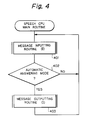
- Fig. 4 which shows a main routine of the speech CPU 21, at step 401, an answer message is input.
- step 402 it is determined whether or not the control is in an automatic answering mode. Only if in an automatic answering mode, does the control proceed to step 403 which outputs an answer message.
- step 403 which outputs an answer message.
- step 501 it is determined whether the ID registration start key of the keyboard 6 is pushed. Only if this key is pushed, does the control proceed to step 503. Contrary to this, when this key is not pushed for a predetermined time period, the control proceeds via step 502 to step 509, thus completing this routine.
- step 503 the numbers such as 1, 2, 3, 4, 5 and 6 of channels of the speech memory 22 are displayed on the LCD 7, and at step 504, it is determined whether one of the selection keys of the keyboard 6 is pushed. Only if such an selection key is pushed, does the control proceed to step 506. Contrary to this, when no selection key is pushed for a predetermined time period, the control proceeds via step 505 to step 509 thus completing this routine.
- step 506 it is determined whether or not an ID number, which is, for example, formed by 4 arbitrary decimal digits, is input from the keyboard 6. Only if such an ID number is input, does the control proceed to step 508. Contrary to this, when an ID number is not input for a predetermined time period, the control proceeds via step 507 to step 509, thus completing this routine.
- an ID number which is, for example, formed by 4 arbitrary decimal digits
- the input ID number is written into the EEPROM 12 in correspondence with the selected channel number.
- one ID number can be registered for the selected channel of the speech memory 22.
- step 601 it is determined whether the input start key of the keyboard 6 is pushed. Only if this key is pushed, does the control proceed to step 603. Contrary to this, when this key is not pushed for a predetermined time period, the control proceeds via step 602 to step 612, thus completing this routine.
- step 604 the numbers such as 1, 2, 3, 4, 5 and 6 of channels of the speech memory 22 are displayed on the LCD 7, and at step 604, it is determined whether one of the selection keys of the keyboard 6 is pushed. Only if such an selection key is pushed, does the control proceed to step 606. Contrary to this, when no selection key is pushed for a predetermined time period, the control proceeds via step 605 to step 612 thus completing this routine.
- the master CPU 11 generates an area designating signal for designating one of the record areas of the speech memory 22 in accordance with the selected channel number, and transmits it to the speech CPU 21. Also, at step 607, the master CPU 11 controls the path of a signal from a microphone to the speech memory 22. In this case, the master CPU 11 activates the main microphone 4 or the adapter microphone 5 in accordance with the selection switch (not shown). Further, at step 608, the CPU 11 generates a record start signal and transmits it to the speech CPU 21.
- step 609 it is determined whether the record end key of the keyboard 6 is pushed. Also, at step 610, it is determined whether or not a predetermined time period has passed. As a result, when the record end key is pushed or the predetermined time period has passed, the control proceeds to step 611 which generates a record end signal and transmits it to the speech CPU 21.
- step 701 it is determined whether or not an area designating signal from the master CPU 11 is received. Only if this area designating signal is received by the speech CPU 21, does the control proceed to step 703. Contrary to this, when this area designating signal has not been received by the speech CPU 21 for a predetermined time period, the control proceeds via step 702 to step 709, thus completing this routine.
- the speech CPU 21 makes the memory control unit 23 designate a record area of the speech memory 22 in accordance with the received area designating signal.
- the speech CPU 21 makes the memory control unit 23 start a write (record) operation of the speech memory 22 for the main microphone 4 or the adapter microphone 5.
- the speech CPU 21 awaits a record end signal from the master CPU 11.
- the speech CPU 21 makes the memory control unit 23 complete the write (record) operation of the speech memory 22 for the main microphone 4 or the adapter microphone 5.
- step 709 the routine of Fig. 7 is completed by step 709.
- a plurality of answer messages can be stored in the record areas of the speech memory 22.
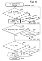
- step 801 it is determined whether or not a call from the radio unit 3 is received. Only if such a call is received by the master CPU 11, does the control proceed to step 803. Contrary to this, when a call has not been received by the master CPU 11 for a predetermined time period, the control proceeds via step 802 to step 810, thus completing this routine.
- the master CPU 11 At step 803, the master CPU 11 generates an ID reception preparing signal for a calling party and transmits it to the speech CPU 21, and at step 804, the master CPU 11 awaits an acknowledgement of receipt from the speech CPU 21.
- step 805 which generates an ID reception requesting signal for the calling party and transmits it to the speech CPU 21.
- step 806 the master CPU 11 awaits a four-digit ID number from the speech CPU 21 for a predetermined time period. Only if such an ID number is received by the master CPU 11, does the control proceed to step 808. Contrary to this, when such an ID number has not been received by the master CPU 11 for the predetermined time period, the control proceeds via step 802 to step 810, thus completing this routine.
- step 808 it is determined whether or not the ID number received by the speech CPU 21 is located in the EEPROM 12. As a result, if such an ID number is located in the EEPROM 12, the control proceeds to step 809. Otherwise, the control proceeds directly to step 810.
- the master CPU 11 generates an output indicating signal for designating one of the record areas of the speech memory 22 in accordance with the received ID number and transmits it to the speech CPU 21.
- step 810 the routine of Fig. 8 is completed by step 810.
- step 901 it is determined whether or not an ID reception preparing signal from the master CPU 11 (see: step 803 of Fig. 8) is received. Only if this ID reception preparing signal is received by the speech CPU 21, does the control proceed to step 903. Contrary to this, when this ID reception preparing signal has not been received by the speech CPU 21 for a predetermined time period, the control proceeds via step 902 to step 912, thus completing this routine.
- the speech CPU 21 makes the memory control unit 23 designate a predetermined record area of the speech memory 22 to generate a message such as "Please key in a four-digit ID.”
- the speech CPU 21 generates an acknowledgement of receipt of the reception preparing signal from the master CPU 11 and transmits it to the master CPU 11 (see step 804 of Fig. 8).
- the speech CPU 21 awaits an ID reception requesting signal from the master CPU 11.
- the control proceeds to step 906.
- step 906 it is determined whether or not an ID designating signal from the master CPU 11 is received. Only if such an ID number is received by the speech CPU 21, does the control proceed to step 908. Contrary to this, when such an ID number has not been received by the speech CPU 21 for a predetermined time period, the control proceeds via step 902 to step 912, thus completing this routine.
- the speech CPU 21 transmits the received ID number to the master CPU 11 (see step 806 of Fig. 8).
- step 909 it is determined whether or not an output indicating signal from the master CPU 11 is received. Only if this output indicating signal is received by the speech CPU 21, does the control proceed to step 911. Contrary to this, when such an output indicating signal has not been received by the speech CPU 21 for a predetermined time period, the control proceeds via step 910 to step 912, thus completing this routine.
- the speech CPU 21 makes the memory control unit 23 designate one of the record areas of the speech memory 22, thus outputting an answer message in response to the received ID number.
- confidential answer messages can be output to specific calling parties.
Landscapes
- Engineering & Computer Science (AREA)
- Computer Security & Cryptography (AREA)
- Signal Processing (AREA)
- Mobile Radio Communication Systems (AREA)
Description
"Please key in a four-digit ID."
Claims (4)
- A radio telephone apparatus having an automatic answering function comprising:wherein said first control circuit (11) includes:a) a radio unit (3):b) a speech memory (22) connected to said radio unit (3), said speech memory being divided into a plurality of record areas, each area for storing an answer message;c) a correspondence table memory (12) for storing a correspondence between identification numbers and said record areas;d) an identification number receiving circuit (24), connected to said radio unit (3), for receiving one of said identification numbers from a caller;e) a first control circuit (11) connected to said radio unit (3) and said correspondence table memory (12), andf) a second control circuit (21) connected via a memory control unit (2) to said speech memory (22), to said identification number receiving circuit (24) and to said first control circuit (11),wherein said second control circuit (21) includes:e1) means for determining whether or not said radio unit (3) is receiving a call:e2) means for transmitting an identification number reception preparing signal to said second control circuit (21) in response to said call being received by said radio unit (3),e3) means for transmitting an identification number reception requesting signal to said second control circuit (21) in response to said identification number reception signal being received by said second control circuit (21),e4) means for determining whether or not an identification number received by said second control circuit (21) is located in said correspondence table memory (12),e5) means for transmitting an output indicating signal to said second control circuit (21) in response to said identification number being located in said correspondence table memory (12),e6) means for transmitting an area designating signal for designating one of said record areas to said second control circuit (21) in response to a pushing operation of a selection key;e7) means for transmitting a record start signal to said second control circuit (21) after said area designating signal is transmitted from said first control circuit (11) to said second control circuit; ande8) means for transmitting a record end signal to said second control circuit (21) in response to a pushing operation of a record end key; andf1) means for transmitting a first message from said speech memory (22) to said radio unit (3) in response to said identification number reception preparing signal from said first control circuit (11),f2) means for receiving said identification number from said identification number receiving circuit (24) in response to said identification number reception requesting signal from said first control circuit (11),f3) means for transmitting said identification number to said first control circuit (11),f4) means for transmitting a second message to said radio unit (3) in response to said output indicating signal from said first control circuit (11), said second message being derived from one of said record areas which corresponds in said correspondence table memory (12) to said identification number,f5) means for designating one of said record areas of said speech memory (22) in response to said area designating signal from said first control circuit (11),f6) means for starting a write operation of a message on said one of record areas of said speech memory (22) in response to said record start signal from said first control circuit (11), andf7) means for ending said write operation in response to said record end signal from said first control circuit.
- An apparatus as set forth in claim 1, wherein said first control circuit (11) further comprises means for registering said identification number in said correspondence table memory (12).
- An apparatus as set forth in claims 1 or 2, wherein said correspondence table memory (12) comprises a nonvolatile memory.
- An apparatus as set forth in any of claims 1 to 3, wherein said identification number receiving circuit (24) comprises a DTMF receiving unit.
Applications Claiming Priority (2)
| Application Number | Priority Date | Filing Date | Title |
|---|---|---|---|
| JP4104450A JPH0646124A (en) | 1992-04-23 | 1992-04-23 | Telephone set with automatic responding function |
| JP104450/92 | 1992-04-23 |
Publications (2)
| Publication Number | Publication Date |
|---|---|
| EP0567135A1 EP0567135A1 (en) | 1993-10-27 |
| EP0567135B1 true EP0567135B1 (en) | 1999-01-07 |
Family
ID=14380970
Family Applications (1)
| Application Number | Title | Priority Date | Filing Date |
|---|---|---|---|
| EP93106581A Expired - Lifetime EP0567135B1 (en) | 1992-04-23 | 1993-04-22 | Telephone answering apparatus having a plurality of selectable outgoing messages |
Country Status (7)
| Country | Link |
|---|---|
| US (1) | US5475739A (en) |
| EP (1) | EP0567135B1 (en) |
| JP (1) | JPH0646124A (en) |
| KR (1) | KR970004228B1 (en) |
| AU (1) | AU660076B2 (en) |
| CA (1) | CA2092352C (en) |
| DE (1) | DE69322898T2 (en) |
Families Citing this family (35)
| Publication number | Priority date | Publication date | Assignee | Title |
|---|---|---|---|---|
| DE3722336C1 (en) * | 1987-07-07 | 1989-03-23 | Ifm Electronic Gmbh | Electronic, preferably non-contact switching device |
| JP2546501B2 (en) * | 1993-07-12 | 1996-10-23 | 日本電気株式会社 | Radiotelephone device, radiotelephone system including the same, and radiotelephone response method |
| DE4402901A1 (en) * | 1994-02-02 | 1995-08-03 | Sel Alcatel Ag | Device and method for storing and reproducing digital data |
| FR2718592B1 (en) * | 1994-04-12 | 1996-07-05 | Flipeaux Jean Luc | Telephone answering device. |
| JPH0833049A (en) * | 1994-07-19 | 1996-02-02 | Mitsubishi Electric Corp | Portable radio communication equipment |
| DE4446520A1 (en) * | 1994-12-24 | 1996-06-27 | Sel Alcatel Ag | Method for issuing an announcement in one of several languages and apparatus therefor |
| DE4446507A1 (en) * | 1994-12-24 | 1996-06-27 | Sel Alcatel Ag | Digital phone |
| FR2731121B1 (en) * | 1995-02-23 | 1997-04-04 | Alcatel Business Systems | METHOD FOR STORING ANNOUNCEMENTS IN TELEPHONE OR RADIO-TELEPHONE ANSWERING APPARATUS, AND SUBSCRIBER APPARATUS IMPLEMENTING SUCH A METHOD |
| JP3281753B2 (en) * | 1995-03-31 | 2002-05-13 | シャープ株式会社 | Answering machine |
| US5884159A (en) * | 1995-11-27 | 1999-03-16 | Motorola, Inc. | Method of spawning a communication service |
| FI101661B1 (en) * | 1996-01-08 | 1998-07-31 | Nokia Mobile Phones Ltd | Activate the phone's own answering machine according to the caller's number |
| US6073101A (en) | 1996-02-02 | 2000-06-06 | International Business Machines Corporation | Text independent speaker recognition for transparent command ambiguity resolution and continuous access control |
| US5966651A (en) * | 1996-03-28 | 1999-10-12 | Motorola, Inc. | Apparatus for communicating a user created message from a portable transceiver to a caller |
| EP0831630A1 (en) * | 1996-09-06 | 1998-03-25 | Siemens Aktiengesellschaft | Telecommunication terminal |
| CA2186926A1 (en) * | 1996-10-01 | 1998-04-01 | Peter Couse | Customized telephone greeting system |
| US5883942A (en) * | 1996-11-20 | 1999-03-16 | Cybiotronics, Ltd. | Voice caller I.D. apparatus |
| DE19648991A1 (en) * | 1996-11-26 | 1998-06-04 | Zeno Datenverarbeitungs Gmbh | Switching unit for mobile telephone |
| SE9701669L (en) * | 1997-05-02 | 1999-02-05 | Anders Bjoerhn | Procedure and device in telephone |
| US5924070A (en) * | 1997-06-06 | 1999-07-13 | International Business Machines Corporation | Corporate voice dialing with shared directories |
| US5897616A (en) | 1997-06-11 | 1999-04-27 | International Business Machines Corporation | Apparatus and methods for speaker verification/identification/classification employing non-acoustic and/or acoustic models and databases |
| US6240170B1 (en) * | 1997-06-20 | 2001-05-29 | Siemens Information And Communication Networks, Inc. | Method and apparatus for automatic language mode selection |
| JPH11112647A (en) * | 1997-09-30 | 1999-04-23 | Nec Mobile Commun Ltd | Message reception system for mobile telephone set |
| KR100263742B1 (en) * | 1998-02-02 | 2000-08-01 | 이면우 | A portable equipment and a method for transmitting and playing message between two of them |
| EP0939535A3 (en) * | 1998-02-27 | 1999-12-29 | Siemens Aktiengesellschaft | Answering machine |
| US6377795B1 (en) * | 1998-03-10 | 2002-04-23 | Lanae E. Bach | Cellular phone with special standby feature |
| US6226363B1 (en) | 1998-04-20 | 2001-05-01 | James H. Miller | Method and system for the recording and selective accessing of messages using a computer, a remote unit, and a public communication system |
| JP2000115838A (en) | 1998-09-30 | 2000-04-21 | Mitsubishi Electric Corp | Mobile communication terminal |
| US7142841B1 (en) * | 2000-09-28 | 2006-11-28 | Texas Instruments Incorporated | Telephone personal information manager |
| US20030023688A1 (en) * | 2001-07-26 | 2003-01-30 | Denenberg Lawrence A. | Voice-based message sorting and retrieval method |
| SE520635C2 (en) | 2001-12-13 | 2003-08-05 | Ericsson Telefon Ab L M | Voicemail system, procedure and wireless telecommunication system for A subscriber to choose message format and level of detail on B subscriber information |
| US20050002498A1 (en) * | 2003-07-01 | 2005-01-06 | Yi-Ming Kao | Method of notifying a caller of a telephone profile status |
| US8000685B2 (en) * | 2005-06-13 | 2011-08-16 | Alcatel Lucent | Network support for distinctive voicemail greeting |
| US20070263784A1 (en) * | 2006-04-10 | 2007-11-15 | Forrer Thomas R Jr | Automated voice answering system correlated to user calendar to provide telephone voice responses based upon user schedule |
| CN101605162A (en) * | 2008-06-10 | 2009-12-16 | 鸿富锦精密工业(深圳)有限公司 | Communication means and device |
| EP2296357A1 (en) * | 2009-09-11 | 2011-03-16 | Unione Consulenti Srl | Multiple message answer machine with ID recognition |
Citations (1)
| Publication number | Priority date | Publication date | Assignee | Title |
|---|---|---|---|---|
| WO1989012937A1 (en) * | 1988-06-16 | 1989-12-28 | Celcom Australia Pty. Ltd. | Telephone answering apparatus for mobile telephone systems |
Family Cites Families (10)
| Publication number | Priority date | Publication date | Assignee | Title |
|---|---|---|---|---|
| US4122306A (en) * | 1975-11-24 | 1978-10-24 | Jacob Friedman | Telephone answering apparatus providing selective message communication |
| US4517410A (en) * | 1982-04-02 | 1985-05-14 | Data Acquisition Services | Automatic user selected variable telephone message record and playback system |
| US4591664A (en) * | 1982-11-23 | 1986-05-27 | Michael Freeman | Multichannel interactive telephone answering apparatus |
| US4847889B1 (en) * | 1988-02-02 | 1996-06-18 | Eswaran Kapali | Single-line plug-in telephone answering machine |
| JPH02202751A (en) * | 1989-02-01 | 1990-08-10 | Takachiho Tsushin Kiki Seisakusho:Kk | Cordless telephone set |
| JPH02268054A (en) * | 1989-04-10 | 1990-11-01 | Sharp Corp | Communication terminal equipment with automatic answering telephone function |
| US4985913A (en) * | 1989-08-29 | 1991-01-15 | Stephen R. Shalom | Multiple message answering machine keyed to the incoming phone number |
| JP2765161B2 (en) * | 1990-02-23 | 1998-06-11 | ソニー株式会社 | Cordless phone |
| JPH0831909B2 (en) * | 1990-06-18 | 1996-03-27 | 松下電器産業株式会社 | Cordless answering machine |
| US5251250A (en) * | 1990-09-12 | 1993-10-05 | Alpine Electronics, Inc. | Method of storing callers telephone numbers in during-absence automatic telephone answering state |
-
1992
- 1992-04-23 JP JP4104450A patent/JPH0646124A/en active Pending
-
1993
- 1993-03-24 AU AU35500/93A patent/AU660076B2/en not_active Ceased
- 1993-03-24 CA CA002092352A patent/CA2092352C/en not_active Expired - Fee Related
- 1993-04-07 US US08/043,860 patent/US5475739A/en not_active Expired - Fee Related
- 1993-04-22 DE DE69322898T patent/DE69322898T2/en not_active Expired - Fee Related
- 1993-04-22 EP EP93106581A patent/EP0567135B1/en not_active Expired - Lifetime
- 1993-04-22 KR KR1019930006771A patent/KR970004228B1/en not_active IP Right Cessation
Patent Citations (1)
| Publication number | Priority date | Publication date | Assignee | Title |
|---|---|---|---|---|
| WO1989012937A1 (en) * | 1988-06-16 | 1989-12-28 | Celcom Australia Pty. Ltd. | Telephone answering apparatus for mobile telephone systems |
Also Published As
| Publication number | Publication date |
|---|---|
| AU3550093A (en) | 1993-10-28 |
| EP0567135A1 (en) | 1993-10-27 |
| US5475739A (en) | 1995-12-12 |
| DE69322898D1 (en) | 1999-02-18 |
| JPH0646124A (en) | 1994-02-18 |
| AU660076B2 (en) | 1995-06-08 |
| CA2092352C (en) | 1996-12-31 |
| KR970004228B1 (en) | 1997-03-26 |
| KR930022790A (en) | 1993-11-24 |
| CA2092352A1 (en) | 1993-10-24 |
| DE69322898T2 (en) | 1999-07-01 |
Similar Documents
| Publication | Publication Date | Title |
|---|---|---|
| EP0567135B1 (en) | Telephone answering apparatus having a plurality of selectable outgoing messages | |
| EP0763958B1 (en) | Radio communication apparatus | |
| US4600809A (en) | Telephone systems | |
| US4263480A (en) | Pager receiver | |
| JP3098442B2 (en) | Telephone system | |
| US4985913A (en) | Multiple message answering machine keyed to the incoming phone number | |
| US4336524A (en) | Video display pager receiver with memory | |
| US5128980A (en) | Automatic paging telephone set and method for controlling thereof | |
| CA1248650A (en) | Telephone apparatus | |
| GB2287856A (en) | Relaying calling party information to a remote receiver | |
| CA2141042A1 (en) | Method for memory dialing for cellular telephones | |
| US4220820A (en) | Control circuitry for a radio telephone | |
| US5485513A (en) | Circuit and method for automatic memory dialing | |
| KR19990018666A (en) | How to remotely verify your phone number | |
| JP2904052B2 (en) | Password verification method | |
| KR940005527B1 (en) | Automatic answering telephone system | |
| KR100237643B1 (en) | Caller data certifying method of a keyphone system | |
| KR100617800B1 (en) | Method for anouncing input telephon number in digital portable telephone | |
| KR0121961B1 (en) | Driving method of answering machine | |
| US5974307A (en) | Method and system communicating with a voice response unit over a cellular telephone network | |
| EP0410461B1 (en) | Facsimile communication device | |
| KR960011702B1 (en) | Man history display method in calling mode of memory telephone | |
| CA1185026A (en) | Dialing device and method | |
| EP0660571A1 (en) | Automatic call screening for answering machines and smart telephones | |
| JPS63272152A (en) | Key telephone system |
Legal Events
| Date | Code | Title | Description |
|---|---|---|---|
| PUAI | Public reference made under article 153(3) epc to a published international application that has entered the european phase |
Free format text: ORIGINAL CODE: 0009012 |
|
| 17P | Request for examination filed |
Effective date: 19930728 |
|
| AK | Designated contracting states |
Kind code of ref document: A1 Designated state(s): DE GB IT |
|
| 17Q | First examination report despatched |
Effective date: 19960517 |
|
| GRAG | Despatch of communication of intention to grant |
Free format text: ORIGINAL CODE: EPIDOS AGRA |
|
| GRAG | Despatch of communication of intention to grant |
Free format text: ORIGINAL CODE: EPIDOS AGRA |
|
| GRAG | Despatch of communication of intention to grant |
Free format text: ORIGINAL CODE: EPIDOS AGRA |
|
| GRAH | Despatch of communication of intention to grant a patent |
Free format text: ORIGINAL CODE: EPIDOS IGRA |
|
| GRAH | Despatch of communication of intention to grant a patent |
Free format text: ORIGINAL CODE: EPIDOS IGRA |
|
| GRAA | (expected) grant |
Free format text: ORIGINAL CODE: 0009210 |
|
| AK | Designated contracting states |
Kind code of ref document: B1 Designated state(s): DE GB IT |
|
| REF | Corresponds to: |
Ref document number: 69322898 Country of ref document: DE Date of ref document: 19990218 |
|
| ITF | It: translation for a ep patent filed |
Owner name: MODIANO & ASSOCIATI S.R.L. |
|
| PLBE | No opposition filed within time limit |
Free format text: ORIGINAL CODE: 0009261 |
|
| STAA | Information on the status of an ep patent application or granted ep patent |
Free format text: STATUS: NO OPPOSITION FILED WITHIN TIME LIMIT |
|
| 26N | No opposition filed | ||
| REG | Reference to a national code |
Ref country code: GB Ref legal event code: IF02 |
|
| PG25 | Lapsed in a contracting state [announced via postgrant information from national office to epo] |
Ref country code: IT Free format text: LAPSE BECAUSE OF NON-PAYMENT OF DUE FEES;WARNING: LAPSES OF ITALIAN PATENTS WITH EFFECTIVE DATE BEFORE 2007 MAY HAVE OCCURRED AT ANY TIME BEFORE 2007. THE CORRECT EFFECTIVE DATE MAY BE DIFFERENT FROM THE ONE RECORDED. Effective date: 20050422 |
|
| PGFP | Annual fee paid to national office [announced via postgrant information from national office to epo] |
Ref country code: GB Payment date: 20060419 Year of fee payment: 14 |
|
| PGFP | Annual fee paid to national office [announced via postgrant information from national office to epo] |
Ref country code: DE Payment date: 20060420 Year of fee payment: 14 |
|
| GBPC | Gb: european patent ceased through non-payment of renewal fee |
Effective date: 20070422 |
|
| PG25 | Lapsed in a contracting state [announced via postgrant information from national office to epo] |
Ref country code: DE Free format text: LAPSE BECAUSE OF NON-PAYMENT OF DUE FEES Effective date: 20071101 |
|
| PG25 | Lapsed in a contracting state [announced via postgrant information from national office to epo] |
Ref country code: GB Free format text: LAPSE BECAUSE OF NON-PAYMENT OF DUE FEES Effective date: 20070422 |