EP0566723B1 - Body spray nozzle - Google Patents
Body spray nozzle Download PDFInfo
- Publication number
- EP0566723B1 EP0566723B1 EP19920924291 EP92924291A EP0566723B1 EP 0566723 B1 EP0566723 B1 EP 0566723B1 EP 19920924291 EP19920924291 EP 19920924291 EP 92924291 A EP92924291 A EP 92924291A EP 0566723 B1 EP0566723 B1 EP 0566723B1
- Authority
- EP
- European Patent Office
- Prior art keywords
- valve element
- nozzle
- spray nozzle
- spray
- stationary
- Prior art date
- Legal status (The legal status is an assumption and is not a legal conclusion. Google has not performed a legal analysis and makes no representation as to the accuracy of the status listed.)
- Expired - Lifetime
Links
- 239000007921 spray Substances 0.000 title claims abstract description 65
- 239000012530 fluid Substances 0.000 claims description 19
- 230000037361 pathway Effects 0.000 claims description 12
- 238000004891 communication Methods 0.000 claims description 4
- 230000000717 retained effect Effects 0.000 claims description 3
- 230000010355 oscillation Effects 0.000 abstract description 7
- XLYOFNOQVPJJNP-UHFFFAOYSA-N water Substances O XLYOFNOQVPJJNP-UHFFFAOYSA-N 0.000 description 20
- 238000001125 extrusion Methods 0.000 description 3
- 238000010276 construction Methods 0.000 description 2
- 230000000694 effects Effects 0.000 description 2
- 238000004140 cleaning Methods 0.000 description 1
- 238000012423 maintenance Methods 0.000 description 1
- 238000012986 modification Methods 0.000 description 1
- 230000004048 modification Effects 0.000 description 1
- 230000002265 prevention Effects 0.000 description 1
Images



Classifications
-
- B—PERFORMING OPERATIONS; TRANSPORTING
- B05—SPRAYING OR ATOMISING IN GENERAL; APPLYING FLUENT MATERIALS TO SURFACES, IN GENERAL
- B05B—SPRAYING APPARATUS; ATOMISING APPARATUS; NOZZLES
- B05B1/00—Nozzles, spray heads or other outlets, with or without auxiliary devices such as valves, heating means
- B05B1/14—Nozzles, spray heads or other outlets, with or without auxiliary devices such as valves, heating means with multiple outlet openings; with strainers in or outside the outlet opening
- B05B1/16—Nozzles, spray heads or other outlets, with or without auxiliary devices such as valves, heating means with multiple outlet openings; with strainers in or outside the outlet opening having selectively- effective outlets
- B05B1/1627—Nozzles, spray heads or other outlets, with or without auxiliary devices such as valves, heating means with multiple outlet openings; with strainers in or outside the outlet opening having selectively- effective outlets with a selecting mechanism comprising a gate valve, a sliding valve or a cock
- B05B1/1636—Nozzles, spray heads or other outlets, with or without auxiliary devices such as valves, heating means with multiple outlet openings; with strainers in or outside the outlet opening having selectively- effective outlets with a selecting mechanism comprising a gate valve, a sliding valve or a cock by relative rotative movement of the valve elements
-
- B—PERFORMING OPERATIONS; TRANSPORTING
- B05—SPRAYING OR ATOMISING IN GENERAL; APPLYING FLUENT MATERIALS TO SURFACES, IN GENERAL
- B05B—SPRAYING APPARATUS; ATOMISING APPARATUS; NOZZLES
- B05B15/00—Details of spraying plant or spraying apparatus not otherwise provided for; Accessories
- B05B15/60—Arrangements for mounting, supporting or holding spraying apparatus
- B05B15/65—Mounting arrangements for fluid connection of the spraying apparatus or its outlets to flow conduits
- B05B15/652—Mounting arrangements for fluid connection of the spraying apparatus or its outlets to flow conduits whereby the jet can be oriented
-
- B—PERFORMING OPERATIONS; TRANSPORTING
- B05—SPRAYING OR ATOMISING IN GENERAL; APPLYING FLUENT MATERIALS TO SURFACES, IN GENERAL
- B05B—SPRAYING APPARATUS; ATOMISING APPARATUS; NOZZLES
- B05B3/00—Spraying or sprinkling apparatus with moving outlet elements or moving deflecting elements
- B05B3/14—Spraying or sprinkling apparatus with moving outlet elements or moving deflecting elements with oscillating elements; with intermittent operation
-
- B—PERFORMING OPERATIONS; TRANSPORTING
- B05—SPRAYING OR ATOMISING IN GENERAL; APPLYING FLUENT MATERIALS TO SURFACES, IN GENERAL
- B05B—SPRAYING APPARATUS; ATOMISING APPARATUS; NOZZLES
- B05B1/00—Nozzles, spray heads or other outlets, with or without auxiliary devices such as valves, heating means
- B05B1/14—Nozzles, spray heads or other outlets, with or without auxiliary devices such as valves, heating means with multiple outlet openings; with strainers in or outside the outlet opening
- B05B1/18—Roses; Shower heads
-
- Y—GENERAL TAGGING OF NEW TECHNOLOGICAL DEVELOPMENTS; GENERAL TAGGING OF CROSS-SECTIONAL TECHNOLOGIES SPANNING OVER SEVERAL SECTIONS OF THE IPC; TECHNICAL SUBJECTS COVERED BY FORMER USPC CROSS-REFERENCE ART COLLECTIONS [XRACs] AND DIGESTS
- Y10—TECHNICAL SUBJECTS COVERED BY FORMER USPC
- Y10T—TECHNICAL SUBJECTS COVERED BY FORMER US CLASSIFICATION
- Y10T137/00—Fluid handling
- Y10T137/8593—Systems
- Y10T137/877—With flow control means for branched passages
- Y10T137/87788—With valve or movable deflector at junction
- Y10T137/87804—Valve or deflector is tubular passageway
Definitions
- This invention relates primarily to body spray nozzles wherein the spray pattern can be easily adjusted. More particularly, the invention relates to nozzles of the foregoing type which can be oscillated in a shower fixture.
- the present invention provides a body spray nozzle for use in a housing and of a type wherein the flow path of fluid from outlets in the valve can be interchanged to produce two kinds of sprays, comprising : a valve body having an inlet portion and an outlet portion; a stationary valve element connected to said housing in said inlet portion, said stationary valve element having at least one fluid passage therethrough to define a fluid pathway; a movable valve element having a first wall portion extending over a portion of the stationary valve element at an inlet side thereof, said movable valve element having a first aperture for alignment with said fluid pathway in said stationary valve element to provide a first fluid pathway, said movable valve element having a second aperture to provide a second fluid pathway in conjunction with said stationary valve element said movable valve element having a second wall extending from said first wall to the outside of said housing; and a nozzle member receivable in said housing, said nozzle member having first and second spray portions; wherein the stationary valve element and the movable valve element are constructed and arranged to provide communication of
- the movable valve element is of a generally cup-shape with first wall portion forming the base thereof.
- first and second apertures of the movable valve element are disposed on different diameters of the first wall portion.
- the invention provides a body spray nozzle of the above kind which is durable in its construction and is not easily disassembled during use; which is aesthetically attractive; and which is adaptable to be oscillated in a shower fixture.
- Fig. 1 is a perspective view showing the spray nozzles of this invention in a shower enclosure.
- Fig. 2 is an enlarged perspective view showing the back of the enclosure shown in Fig. 1.
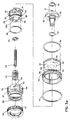
- Figs. 3a and 3b are assembly views of one of the spray nozzles of this invention.
- Fig. 4 is a view in section taken along line 4-4 of Fig. 2.
- Fig. 5 is a view in vertical section showing one of the spray nozzles of this invention in one mode of operation.
- Fig. 6 is a view taken along line 6-6 of Fig. 5.
- Fig. 7 is a view similar to Fig. 5 showing the body spray nozzle in another mode of operation.
- Fig. 8 is a view taken along line 8-8 of Fig. 7.
- Fig. 9 is a partial and enlarged view showing the placement of a bearing member in the nozzle housing.
- Fig. 10 is a view in vertical section illustrating the non-rotation prevention means of the nozzle in conjunction with a bearing member.
- Fig. 11 is a view in partial vertical section illustrating the pivoting of the spray nozzle.
- the spray nozzles generally 10 are mounted in the panel housing 11 which also contains the usual mixing valve 12.
- the panel housing is mounted to a wall 19 forming a part of a shower fixture.
- two spray nozzles are depicted and are disposed for oscillation as will be described later in conjunction with Fig. 2.
- the spray nozzles include a housing 13 to which is threadably attached such as by threads 16, the back flange portion 15.
- a water inlet as indicated at 17 feeds water to the valve body 20 which is in the form of an eye.
- a bearing 22 is disposed between the housing 13 and the valve body 20.
- Appropriate O-type seals 26 and 27 are provided between the bearing 22 and the seal 23 as well as the bearing 22 and the flange 15.
- Water passages 29 are provided in the valve body 20 to deliver water into the cavity 30 of the valve body 20.
- a sleeve assembly 40 Disposed in the cavity 30 is a sleeve assembly 40 having a back wall 42 and a side wall 44.
- a hub member 32 extends through the back wall 42 of the sleeve assembly 40 and abuts against the wall 42 with the shoulder 45. Hub member 32 is secured to the valve body 20 by the screw 34 and the washer 35.
- the hub 32 has the water passages 33 for communication with the water passages 29 in the valve body 20.
- a stem member 36 is frictionally received over the hub 32 and retains the sleeve assembly 40 onto the hub 32 in a rotatable manner such as between the end wall 28 of the stem member 36 and the shoulder 45 of the hub member 32.
- a nozzle portion 47 is retained over the stem 36 such as by the projections 43 extending from the stem 36 and the bayonet type slots 54 in the annular body section 58 of nozzle portion 47. This is best seen in conjunction with Fig. 3a.
- An appropriate seal 39 is placed between the stem 36 and the nozzle portion 47.
- a spring 53 is housed in the nozzle cavity 51 for biasing the nozzle portion 47 onto the stem 36 in conjunction with the projections 43 and the bayonet slots 54.
- An outer spray ring 50 is secured to the nozzle portion 47 and has the outer nozzle spray passages 57, whereas the central portion has the inner spray passages 48. This is best seen in conjunction with Fig. 10.
- FIGs. 5 and 6 there the position of the sleeve assembly 40 is such that the water flow through the spray nozzles 10 and 10' will be from the inlet 17 and out through the center spray passages 48 of the nozzle portion 47. This is effected by orienting the inner fluid passages 46 of the sleeve assembly 40 with the elongated passages 38 in the stem 36. The inner fluid passages 46 are seen in Figs. 3a and 8.
- the two spray nozzles 10 and 10' are pivotally mounted in the extrusion 62 of the panel housing 11 to comprise a shower apparatus generally 60.
- the spray nozzles 10 and 10' are mounted in casing rings 64 which in turn are connected to the panel extrusion 62 by brackets 65 and screws 66.
- Opposing pivot pins 67 and 69 are threaded in the casing ring 64 and extend into the openings 68 and 70 of the valve body 13.
- Upper and lower pivotal bearing surfaces are provided by the brackets 71 and 75 which are mounted onto the valve housing 13 of each spray nozzle 10 and 10' such as by the screws 73. This is best seen in Fig. 11.
- Brackets 75 are in turn connected to linkage members 77, such as by the shoulder screws 74, which in turn connect to rod member 80 by means of the connectors 82 and screws 74.
- Suitable guides 84 are provided for the rod 80, and a bearing 86 which is attached to rod 80 provides for rotatable support on the lower guide member 84'.
- Rod 80 is interconnected to an oscillating hub 90 of an oscillating motor 92 through the link 88.
- a switch 94 is placed in close proximity to the oscillating hub 90. The purpose of this switch is to provide a means through suitable electronics for always orienting spray nozzles in a central position when they are turned off.
- Water is delivered to the spray nozzles 10 and 10' through the inlet hoses 96 and 97 which will connect to the respective water inlets 17 of the spray nozzles 10 and 10'.
- the hose 98 will be connected to the mixing valve 12 and will feed the electronically controlled valves. These valves in turn regulate flow to the inlet hoses 96 and 97.
- a spray nozzle which is of a very durable construction in that a minimum number of parts is required in order to effect different spray patterns. Only the rotation of a sleeve assembly is required to effect this and without any internal gears.
- the sleeve assembly is readily accessible from the front of the nozzle and lends an aesthetic appearance thereto such as with the trim ring 49 in a compact design.
- the spray nozzles are readily adaptable for use in conjunction with an oscillation means wherein the nozzles can be moved from side to side. Further, there is provided herein a linkage and connection means for oscillating the nozzles which lends itself to a compact design in that it can be placed on a single panel extrusion.
- the spray nozzles are easily disassembled by removal of a nozzle portion which provides ready access through the nozzle portion for any cleaning as well to ready access to the inside of the spray nozzles if further disassembly is required.
- the invention provides an improved spray nozzle.
Landscapes
- Nozzles (AREA)
Abstract
Description
- This invention relates primarily to body spray nozzles wherein the spray pattern can be easily adjusted. More particularly, the invention relates to nozzles of the foregoing type which can be oscillated in a shower fixture.
- It is desirable to provide shower type nozzles with different spray patterns to accommodate the likes of the bather. It is known to provide nozzles with different spray patterns which are achieved by rotating a portion of the shower head. For example in U.S. Patent 166,654 different flow paths are obtained in a nozzle head by rotating a cup-like member so as to orient different passages with parts in the nozzle. U.S. Patents 3,558,054 and 3,801,019 also disclose different flow paths in a nozzle structure. In the '054 patent the spray head is rotated and in the '019 patent a shutter plate is used in conjunction with gears and pinions. A problem with these prior art nozzles is that they are not aesthetically appealing, can become disassembled during use or require a multiplicity of moving parts.
- A need exists for an improved nozzle which can overcome the foregoing problems of the prior art.
- The present invention provides a body spray nozzle for use in a housing and of a type wherein the flow path of fluid from outlets in the valve can be interchanged to produce two kinds of sprays, comprising : a valve body having an inlet portion and an outlet portion; a stationary valve element connected to said housing in said inlet portion, said stationary valve element having at least one fluid passage therethrough to define a fluid pathway; a movable valve element having a first wall portion extending over a portion of the stationary valve element at an inlet side thereof, said movable valve element having a first aperture for alignment with said fluid pathway in said stationary valve element to provide a first fluid pathway, said movable valve element having a second aperture to provide a second fluid pathway in conjunction with said stationary valve element said movable valve element having a second wall extending from said first wall to the outside of said housing; and a nozzle member receivable in said housing, said nozzle member having first and second spray portions; wherein the stationary valve element and the movable valve element are constructed and arranged to provide communication of said first fluid pathway with said first nozzle spray portion when in one position and with said second fluid pathway and said second spray portion when said movable valve element is rotated to a second position.
- In a preferred form the movable valve element is of a generally cup-shape with first wall portion forming the base thereof.
- Also preferably the first and second apertures of the movable valve element are disposed on different diameters of the first wall portion.
- The invention provides a body spray nozzle of the above kind which is durable in its construction and is not easily disassembled during use; which is aesthetically attractive; and which is adaptable to be oscillated in a shower fixture.
- These and still other features and advantages of the invention will be apparent from the description which follows. In the detailed description below, the preferred embodiments of the invention will be described in reference to the accompanying drawings. These embodiments do not represent the full scope of the invention. Rather the invention may be employed in other embodiments. Reference should therefore be made to the claims herein for interpreting the breadth of the invention.
- Fig. 1 is a perspective view showing the spray nozzles of this invention in a shower enclosure.
- Fig. 2 is an enlarged perspective view showing the back of the enclosure shown in Fig. 1.
- Figs. 3a and 3b are assembly views of one of the spray nozzles of this invention.
- Fig. 4 is a view in section taken along line 4-4 of Fig. 2.
- Fig. 5 is a view in vertical section showing one of the spray nozzles of this invention in one mode of operation.
- Fig. 6 is a view taken along line 6-6 of Fig. 5.
- Fig. 7 is a view similar to Fig. 5 showing the body spray nozzle in another mode of operation.
- Fig. 8 is a view taken along line 8-8 of Fig. 7.
- Fig. 9 is a partial and enlarged view showing the placement of a bearing member in the nozzle housing.
- Fig. 10 is a view in vertical section illustrating the non-rotation prevention means of the nozzle in conjunction with a bearing member.
- Fig. 11 is a view in partial vertical section illustrating the pivoting of the spray nozzle.
- Referring to Figs. 1 and 2, the spray nozzles generally 10 are mounted in the panel housing 11 which also contains the
usual mixing valve 12. The panel housing is mounted to awall 19 forming a part of a shower fixture. As there indicated, two spray nozzles are depicted and are disposed for oscillation as will be described later in conjunction with Fig. 2. - Referring first to the nozzles per se, these are shown in Figs. 3a, 3b, as well as Figs. 5 and 7. The spray nozzles include a
housing 13 to which is threadably attached such as bythreads 16, theback flange portion 15. A water inlet as indicated at 17 feeds water to thevalve body 20 which is in the form of an eye. Abearing 22 is disposed between thehousing 13 and thevalve body 20. There is also aseal 23 which is biased against thevalve body 20 by means of theconical spring 25. Appropriate O-type seals bearing 22 and theseal 23 as well as the bearing 22 and theflange 15. -
Water passages 29 are provided in thevalve body 20 to deliver water into thecavity 30 of thevalve body 20. Disposed in thecavity 30 is asleeve assembly 40 having aback wall 42 and aside wall 44. Ahub member 32 extends through theback wall 42 of thesleeve assembly 40 and abuts against thewall 42 with theshoulder 45.Hub member 32 is secured to thevalve body 20 by thescrew 34 and thewasher 35. Thehub 32 has thewater passages 33 for communication with thewater passages 29 in thevalve body 20. Astem member 36 is frictionally received over thehub 32 and retains thesleeve assembly 40 onto thehub 32 in a rotatable manner such as between theend wall 28 of thestem member 36 and theshoulder 45 of thehub member 32. There are suitable seals such as 37 placed between thehub member 32 and thevalve body 20 as well as thestem 36. There are arcuate likewater passages back wall 42 of the sleeve assembly 40 (See Fig. 6), and there are twoelongated water passages 38 in thehub 32 member. - A
nozzle portion 47 is retained over thestem 36 such as by theprojections 43 extending from thestem 36 and thebayonet type slots 54 in the annular body section 58 ofnozzle portion 47. This is best seen in conjunction with Fig. 3a. Anappropriate seal 39 is placed between thestem 36 and thenozzle portion 47. Aspring 53 is housed in thenozzle cavity 51 for biasing thenozzle portion 47 onto thestem 36 in conjunction with theprojections 43 and thebayonet slots 54. Anouter spray ring 50 is secured to thenozzle portion 47 and has the outernozzle spray passages 57, whereas the central portion has theinner spray passages 48. This is best seen in conjunction with Fig. 10. - A better understanding of the
spray nozzles 10 will be had by a description of the flow of water through the various passages by means of the rotation of thesleeve assembly 40 to provide the different spray patterns. Looking at Figs. 5 and 6 first, there the position of thesleeve assembly 40 is such that the water flow through thespray nozzles 10 and 10' will be from theinlet 17 and out through thecenter spray passages 48 of thenozzle portion 47. This is effected by orienting theinner fluid passages 46 of thesleeve assembly 40 with theelongated passages 38 in thestem 36. Theinner fluid passages 46 are seen in Figs. 3a and 8. In this manner, water will flow from thewater inlet 17 through thepassages 29 of thevalve body hub 32, through thepassages 46 in thewall 42 of thesleeve assembly 40, through theelongated slots 38 of thestem 36, into thecavity 51 of thenozzle portion 47 and out through thecentral spray passages 48. It should be noted in conjunction with Fig. 6 that in this instance water will not flow through the outerarcuate passages 56 in thesleeve assembly 40 as they will be blocked by theflange portions 41 of thestem 36. - When it is desired to have flow through the outer
water spray passages 57, this is accomplished by rotating thesleeve assembly 40 to the position shown in Figs. 7 and 8. Note in this instance that the rotation is stopped by aprojection stop 55 which extends outwardly from thebase wall 42 of thesleeve assembly 40 to engage aflange portion 41 of the stem. As illustrated in Fig. 8, outerarcuate passages 56 inback wall 42 are now in open communication past theflange portions 41 of thestem 36 whereas theapertures 46 which were previously aligned withwater passages 38 are now disoriented, and consequently any flow is blocked to them. Water will, however, flow through thepassages 56 around the outside of thestem 36, over the outside of thenozzle portion 47 through thegrooves 52 with the water flow ultimately issuing fromspray passages 57. It should be understood that the flow of water frominlet 17 topassages 56 is the same as previously described with respect topassages 46 in conjunction with Fig. 6. - Referring specifically to Figs. 9 and 10, there is shown a means of preventing rotation of the
valve body 20 inside thehousing 13. This is accomplished by fixing thebearing 22 in thehousing 13 by anotch 14 in thehousing 13 and a projection orenlargement 18 extending from thebearing 22. Additionally, thevalve body 20 has the flat portions 20a at opposite sides and the bearing has the flat portions 22a adjacent thereto. Thus as viewed in Fig. 10, this will allow an upward and downward pivoting of thevalve body 20 but will prevent side to side rotation. This will be better understood in conjunction with the following description of the oscillation means wherein a side to side oscillation of thespray nozzles 10 and 10' is provided. - Referring to Figs. 2 and 4, the two
spray nozzles 10 and 10' are pivotally mounted in theextrusion 62 of the panel housing 11 to comprise a shower apparatus generally 60. The spray nozzles 10 and 10' are mounted in casing rings 64 which in turn are connected to thepanel extrusion 62 bybrackets 65 and screws 66. Opposing pivot pins 67 and 69 are threaded in thecasing ring 64 and extend into theopenings valve body 13. Upper and lower pivotal bearing surfaces are provided by thebrackets valve housing 13 of eachspray nozzle 10 and 10' such as by thescrews 73. This is best seen in Fig. 11.Brackets 75 are in turn connected tolinkage members 77, such as by the shoulder screws 74, which in turn connect torod member 80 by means of theconnectors 82 and screws 74.Suitable guides 84 are provided for therod 80, and abearing 86 which is attached torod 80 provides for rotatable support on the lower guide member 84'.Rod 80 is interconnected to anoscillating hub 90 of anoscillating motor 92 through thelink 88. Aswitch 94 is placed in close proximity to theoscillating hub 90. The purpose of this switch is to provide a means through suitable electronics for always orienting spray nozzles in a central position when they are turned off. Water is delivered to thespray nozzles 10 and 10' through theinlet hoses respective water inlets 17 of thespray nozzles 10 and 10'. It should be understood in this instance that thehose 98 will be connected to the mixingvalve 12 and will feed the electronically controlled valves. These valves in turn regulate flow to theinlet hoses - It will therefore be appreciated that a spray nozzle is provided which is of a very durable construction in that a minimum number of parts is required in order to effect different spray patterns. Only the rotation of a sleeve assembly is required to effect this and without any internal gears. The sleeve assembly is readily accessible from the front of the nozzle and lends an aesthetic appearance thereto such as with the
trim ring 49 in a compact design. The spray nozzles are readily adaptable for use in conjunction with an oscillation means wherein the nozzles can be moved from side to side. Further, there is provided herein a linkage and connection means for oscillating the nozzles which lends itself to a compact design in that it can be placed on a single panel extrusion. In the instance where maintenance is required for any reason, the spray nozzles are easily disassembled by removal of a nozzle portion which provides ready access through the nozzle portion for any cleaning as well to ready access to the inside of the spray nozzles if further disassembly is required. Thus, the invention provides an improved spray nozzle. - While the preferred embodiments have been described above, it should be readily apparent to those skilled in the art that a number of modifications and changes may be made without departing from the scope of the invention as defined in the claims. For example, while the spray nozzles have been shown in conjunction with an oscillation means, they are suitable for use as only a single spray nozzle. Further, while two spray nozzles have been shown for oscillation, it is readily apparent that any number of nozzles could be interconnected by the linkage means as described herein. Also, while a specific number of passageways have been described for use in conjunction with the component parts, the number of passageways can also be varied if desired.
Claims (10)
- A body spray nozzle for use in a housing (13) and of a type wherein the flow path of fluid from outlets in the valve can be interchanged to produce two kinds of sprays, comprising : a valve body (20) having an inlet portion and an outlet portion; a stationary valve element (36) connected to said housing in said inlet portion, said stationary valve element having at least one fluid passage (38) therethrough to define a fluid pathway; a movable valve element (40) having a first wall (42) portion extending over a portion of the stationary valve element at an inlet side thereof, said movable valve element having a first aperture (46) for alignment with said fluid pathway in said stationary valve element to provide a first fluid pathway, said movable valve element having a second aperture (56) to provide a second fluid pathway in conjunction with said stationary valve element (36), said movable valve element (40) having a second wall (44) extending from said first wall to the outside of said housing; and a nozzle member (47) receivable in said housing, said nozzle member having first (48) and second (57) spray portions; wherein the stationary valve element (36) and the movable valve element (40) are constructed and arranged to provide communication of said first fluid pathway with said first nozzle spray portion (48) when in one position and with said second fluid pathway and said second spray portion when said movable valve element (40) is rotated to a second position.
- The body spray nozzle of claim 1, characterized in that the movable valve element is of a generally cup-shape with said first wall portion (42) forming the base thereof.
- The body spray nozzle of claim 1, characterized in that the first and second apertures (46,56) of the movable valve element are disposed on different diameters of the first wall portion (42).
- The body spray nozzle of claim 1, characterized in that the stationary valve element (36) is secured to the valve body (20) by a hub member (32).
- The body spray nozzle of claim 1, characterized in that the stationary valve element (36) is formed with two opposing sections with a fluid passage (38) in each section.
- The body spray nozzle of claim 1, characterized in that the hub member (32) has a plurality of apertures (33) for orientation with apertures (29) in the valve body (20).
- The body spray nozzle of claim 1, characterized in that the nozzle member (47) is retained in the valve body (20) by an annular body portion having slots (54) for engagement by projections (43) on the stationary valve element (36).
- The body spray nozzle of claim 1, characterized in that the stationary valve element (36) has a stop surface (41) for engagement by a stop member (55) on the first wall (42) of the movable valve element (40).
- The body spray nozzle of claim 1, characterized in that the valve body (20) is pivotally retained in the housing (13).
- The body spray nozzle of claim 1, characterized in that the second spray portion is circumferentially positioned with respect to the first spray portion (48).
Priority Applications (1)
| Application Number | Priority Date | Filing Date | Title |
|---|---|---|---|
| EP19960105908 EP0723814B1 (en) | 1991-11-08 | 1992-11-05 | Oscillating shower apparatus |
Applications Claiming Priority (3)
| Application Number | Priority Date | Filing Date | Title |
|---|---|---|---|
| US790274 | 1991-11-08 | ||
| US07/790,274 US5205490A (en) | 1991-11-08 | 1991-11-08 | Body spray nozzle |
| PCT/US1992/009516 WO1993008921A1 (en) | 1991-11-08 | 1992-11-05 | Body spray nozzle |
Related Child Applications (2)
| Application Number | Title | Priority Date | Filing Date |
|---|---|---|---|
| EP19960105908 Division EP0723814B1 (en) | 1991-11-08 | 1992-11-05 | Oscillating shower apparatus |
| EP96105908.6 Division-Into | 1996-04-15 |
Publications (3)
| Publication Number | Publication Date |
|---|---|
| EP0566723A1 EP0566723A1 (en) | 1993-10-27 |
| EP0566723A4 EP0566723A4 (en) | 1994-12-07 |
| EP0566723B1 true EP0566723B1 (en) | 1997-09-17 |
Family
ID=25150185
Family Applications (2)
| Application Number | Title | Priority Date | Filing Date |
|---|---|---|---|
| EP19960105908 Expired - Lifetime EP0723814B1 (en) | 1991-11-08 | 1992-11-05 | Oscillating shower apparatus |
| EP19920924291 Expired - Lifetime EP0566723B1 (en) | 1991-11-08 | 1992-11-05 | Body spray nozzle |
Family Applications Before (1)
| Application Number | Title | Priority Date | Filing Date |
|---|---|---|---|
| EP19960105908 Expired - Lifetime EP0723814B1 (en) | 1991-11-08 | 1992-11-05 | Oscillating shower apparatus |
Country Status (4)
| Country | Link |
|---|---|
| US (2) | US5205490A (en) |
| EP (2) | EP0723814B1 (en) |
| CA (1) | CA2096253C (en) |
| WO (1) | WO1993008921A1 (en) |
Families Citing this family (34)
| Publication number | Priority date | Publication date | Assignee | Title |
|---|---|---|---|---|
| US5735467A (en) * | 1996-09-05 | 1998-04-07 | Lee; Cheng-Chung | Three-way adjustable shower device |
| US7082948B2 (en) * | 1997-10-08 | 2006-08-01 | Laughlin Products, Inc. | Method of and apparatus for automatically coating the human body |
| US6881417B1 (en) | 1997-10-08 | 2005-04-19 | Laughlin Products, Inc. | Method, apparatus, and composition for automatically coating the human body with plural components |
| US6886572B2 (en) | 1997-10-08 | 2005-05-03 | Laughlin Products, Inc. | Automated system for coating the human body: virtual motion |
| US6199557B1 (en) * | 1997-10-08 | 2001-03-13 | Laughlin Products, Inc. | Method of and apparatus for automatically coating the human body |
| US7041089B2 (en) * | 1997-10-08 | 2006-05-09 | Laughlin Products, Inc. | Automated system for coating the human body: virtual motion |
| US6439243B2 (en) * | 1997-10-08 | 2002-08-27 | Laughlin Products, Inc. | Method of and apparatus for automatically coating the human body |
| US6431180B2 (en) * | 1997-10-08 | 2002-08-13 | Laughlin Products, Inc. | Automated system for coating the human body |
| US6802830B1 (en) * | 2000-06-16 | 2004-10-12 | Drew Waters | Device and method that generates a fog capable of altering the color of human skin |
| DE10114356A1 (en) * | 2001-03-22 | 2002-09-26 | Hansgrohe Ag | Sanitary device used as a shower, whirlpool, etc. comprises a water outlet nozzle fixed in an opening on a holder by holding devices engaging behind the front side of a front wall |
| US20030094509A1 (en) * | 2001-11-21 | 2003-05-22 | Ralph Venuto | Spray booth |
| US6908047B2 (en) | 2001-12-07 | 2005-06-21 | Nottingham Spirk, Llc | Oscillating shower sprayer |
| US7014128B2 (en) * | 2002-10-01 | 2006-03-21 | Conair Corporation | Showerhead assembly |
| AU2003282855A1 (en) * | 2002-10-31 | 2004-06-07 | Conair Corporation | Hair treatment system and method |
| US7472846B2 (en) * | 2004-01-16 | 2009-01-06 | Masco Corporation Of Indiana | Integrated swivel spray aerator with diverter |
| US7246760B2 (en) * | 2004-02-20 | 2007-07-24 | Masco Corporation Of Indiana | Swivel mount for a spray head |
| DE102005010550B4 (en) * | 2005-03-04 | 2007-03-22 | Neoperl Gmbh | Sanitary water outlet |
| US7766261B1 (en) * | 2005-10-28 | 2010-08-03 | Bowles Fluidics Corporation | Compact fluidic spa nozzle |
| GB2432785B (en) * | 2005-12-05 | 2011-08-10 | Gerald Hipperson | A lotion application compartment |
| DE102007003416A1 (en) * | 2007-01-16 | 2008-07-17 | Hansgrohe Ag | shower |
| US8360346B2 (en) * | 2007-11-01 | 2013-01-29 | Kohler Co. | Bodyspray assembly |
| DE102008031558A1 (en) * | 2008-07-07 | 2010-01-14 | Grohe Ag | Head or side shower |
| US8733674B2 (en) * | 2009-04-30 | 2014-05-27 | Kohler Co. | Body spray nozzle |
| WO2012025030A1 (en) * | 2010-08-23 | 2012-03-01 | 厦门松霖科技有限公司 | Rotary switching water outlet mechanism |
| JP2014104989A (en) * | 2012-11-26 | 2014-06-09 | Mitsubishi Electric Corp | Packing member |
| JP6257341B2 (en) * | 2014-01-16 | 2018-01-10 | 株式会社ミツバ | NOZZLE, MANUFACTURING METHOD THEREOF, AND WASHER NOZZLE |
| US9757740B2 (en) | 2014-11-19 | 2017-09-12 | Kohler Co. | Multi-function sprayhead |
| US9868125B2 (en) * | 2015-01-19 | 2018-01-16 | Moen Incorporated | Multifunction pivoting body spray |
| US10179254B2 (en) * | 2015-09-21 | 2019-01-15 | Apple Inc. | Capacitor structure with acoustic noise self-canceling characteristics |
| DE202015007677U1 (en) * | 2015-11-05 | 2017-02-07 | Neoperl Gmbh | aerator |
| US9707572B2 (en) | 2015-12-18 | 2017-07-18 | Kohler Co. | Multi-function splashless sprayhead |
| DE102016210063B3 (en) * | 2016-06-08 | 2017-08-24 | Hansgrohe Se | Shower unit with selectable jet shaped bodies |
| US20180369850A1 (en) * | 2017-06-22 | 2018-12-27 | Durst Corporation, Inc. | Adjustable Escutcheon Assembly |
| US11130145B2 (en) | 2017-06-22 | 2021-09-28 | Durst Corporation, Inc. | Adjustable escutcheon assembly |
Family Cites Families (25)
| Publication number | Priority date | Publication date | Assignee | Title |
|---|---|---|---|---|
| US166654A (en) * | 1875-08-10 | Improvement in hose-nozzles | ||
| DE29798C (en) * | L. LÖFBERG in Hamburg | Spray lance with full jet or shower | ||
| US910400A (en) * | 1908-02-24 | 1909-01-19 | John W Lischer | Plant-sprinkling apparatus. |
| US2453368A (en) * | 1945-04-26 | 1948-11-09 | Alfred D Goodwin | Spray operating mechanism |
| US2561432A (en) * | 1947-08-07 | 1951-07-24 | Farquhar Company Ab | Sprayer |
| US3261369A (en) * | 1964-07-13 | 1966-07-19 | Ross And White Company | Vehicle cleaning apparatus |
| US3269661A (en) * | 1965-01-14 | 1966-08-30 | Seth W Thompson | Oscillatory lawn sprinkler |
| FR1551892A (en) * | 1967-07-24 | 1969-01-03 | ||
| US3713587A (en) * | 1971-07-22 | 1973-01-30 | W Carson | Shower head |
| US3801019A (en) * | 1972-06-21 | 1974-04-02 | Teledyne Ind | Spray nozzle |
| DE2644765A1 (en) * | 1975-10-10 | 1977-04-14 | Alsons Corp | Spray head for shower bath - has rotating disc system to produce pulsating water delivery |
| US4128017A (en) * | 1977-04-27 | 1978-12-05 | Clarke George C | Variable speed drive |
| US4218017A (en) * | 1978-09-20 | 1980-08-19 | Claber S.P.A. | Oscillable sprinkler for cultivated plots, such as fields, meadows, gardens and the like |
| AT362867B (en) * | 1979-02-07 | 1981-06-25 | Huber Markus | BODY SHOWER |
| US4221338A (en) * | 1979-02-08 | 1980-09-09 | Shames Sidney J | Combination spray and aerator |
| DE2911405C2 (en) * | 1979-03-23 | 1982-12-23 | Hans Grohe Gmbh & Co Kg, 7622 Schiltach | Massage shower head with a device for the optional generation of pulsating and / or non-pulsating liquid jets |
| US4339833A (en) * | 1980-12-31 | 1982-07-20 | Mandell Gerald D | Reciprocating hydro-massage apparatus |
| US4598866A (en) * | 1983-01-19 | 1986-07-08 | Teledyne Industries, Inc. | Showerhead |
| US4674687A (en) * | 1985-08-09 | 1987-06-23 | Teledyne Industries, Inc. | Showerhead |
| US4782551A (en) * | 1985-09-06 | 1988-11-08 | Ballwebber Arnold E | Apparatus for cleaning surfaces |
| US4754928A (en) * | 1987-01-14 | 1988-07-05 | Alsons Corporation | Variable massage showerhead |
| US4826079A (en) * | 1988-04-29 | 1989-05-02 | Gunter Przystawik | Moving means for fountain nozzle |
| DE3901162C2 (en) * | 1989-01-17 | 2000-08-17 | Hansgrohe Ag | Shower cubicle |
| US4944457A (en) * | 1989-05-01 | 1990-07-31 | Mark Brewer | Oscillating device for fluid nozzles |
| US5033897A (en) * | 1990-01-19 | 1991-07-23 | Chen I Cheng | Hand held shower apparatus |
-
1991
- 1991-11-08 US US07/790,274 patent/US5205490A/en not_active Expired - Lifetime
-
1992
- 1992-11-05 WO PCT/US1992/009516 patent/WO1993008921A1/en not_active Ceased
- 1992-11-05 EP EP19960105908 patent/EP0723814B1/en not_active Expired - Lifetime
- 1992-11-05 CA CA 2096253 patent/CA2096253C/en not_active Expired - Fee Related
- 1992-11-05 EP EP19920924291 patent/EP0566723B1/en not_active Expired - Lifetime
-
1993
- 1993-01-19 US US08/006,360 patent/US5299743A/en not_active Expired - Lifetime
Also Published As
| Publication number | Publication date |
|---|---|
| EP0566723A1 (en) | 1993-10-27 |
| CA2096253A1 (en) | 1993-05-09 |
| US5299743A (en) | 1994-04-05 |
| CA2096253C (en) | 1999-05-04 |
| EP0723814B1 (en) | 2002-05-02 |
| EP0723814A2 (en) | 1996-07-31 |
| EP0723814A3 (en) | 1996-12-04 |
| WO1993008921A1 (en) | 1993-05-13 |
| EP0566723A4 (en) | 1994-12-07 |
| US5205490A (en) | 1993-04-27 |
Similar Documents
| Publication | Publication Date | Title |
|---|---|---|
| US5205490A (en) | Body spray nozzle | |
| US5918811A (en) | Showerhead with variable spray patterns and internal shutoff valve | |
| US8905332B2 (en) | Dual turbine showerhead | |
| US5499767A (en) | Shower head having elongated arm, plural nozzles, and plural inlet lines | |
| US4588130A (en) | Showerhead | |
| US4629125A (en) | Spray nozzle | |
| US4754928A (en) | Variable massage showerhead | |
| CA2690919C (en) | Revolving spray shower head | |
| US6533194B2 (en) | Shower head | |
| CA1089897A (en) | Fluid-spray discharge apparatus | |
| US4219160A (en) | Fluid spray nozzle having leak resistant sealing means | |
| US4901927A (en) | Dual shower head assembly | |
| US5050800A (en) | Full range sprinkler nozzle | |
| US7584906B2 (en) | Fluid dampening mechanism incorporated into a water delivery system for modifying a flow pattern | |
| EP0697249A2 (en) | Multi spray pattern shower head | |
| KR20010085628A (en) | Multi-functional shower head | |
| US20090289129A1 (en) | Parent-child showerhead | |
| WO2000003810A2 (en) | Nutating fluid delivery apparatus | |
| US6170765B1 (en) | Pressure actuated shower head mechanism | |
| US6354518B1 (en) | Pressure actuated shower head mechanism | |
| AU8611598A (en) | Pressure actuated shower head mechanism | |
| KR200180454Y1 (en) | Body shower tool of booth type shower bath | |
| HK1003339A1 (en) | Showerhead |
Legal Events
| Date | Code | Title | Description |
|---|---|---|---|
| PUAI | Public reference made under article 153(3) epc to a published international application that has entered the european phase |
Free format text: ORIGINAL CODE: 0009012 |
|
| AK | Designated contracting states |
Kind code of ref document: A1 Designated state(s): FR |
|
| 17P | Request for examination filed |
Effective date: 19930914 |
|
| A4 | Supplementary search report drawn up and despatched | ||
| AK | Designated contracting states |
Kind code of ref document: A4 Designated state(s): FR |
|
| 17Q | First examination report despatched |
Effective date: 19951017 |
|
| GRAG | Despatch of communication of intention to grant |
Free format text: ORIGINAL CODE: EPIDOS AGRA |
|
| GRAH | Despatch of communication of intention to grant a patent |
Free format text: ORIGINAL CODE: EPIDOS IGRA |
|
| GRAH | Despatch of communication of intention to grant a patent |
Free format text: ORIGINAL CODE: EPIDOS IGRA |
|
| GRAA | (expected) grant |
Free format text: ORIGINAL CODE: 0009210 |
|
| AK | Designated contracting states |
Kind code of ref document: B1 Designated state(s): FR |
|
| DX | Miscellaneous (deleted) | ||
| ET | Fr: translation filed | ||
| PLBE | No opposition filed within time limit |
Free format text: ORIGINAL CODE: 0009261 |
|
| STAA | Information on the status of an ep patent application or granted ep patent |
Free format text: STATUS: NO OPPOSITION FILED WITHIN TIME LIMIT |
|
| 26N | No opposition filed | ||
| PGFP | Annual fee paid to national office [announced via postgrant information from national office to epo] |
Ref country code: FR Payment date: 20051021 Year of fee payment: 14 |
|
| REG | Reference to a national code |
Ref country code: FR Ref legal event code: ST Effective date: 20070731 |
|
| PG25 | Lapsed in a contracting state [announced via postgrant information from national office to epo] |
Ref country code: FR Free format text: LAPSE BECAUSE OF NON-PAYMENT OF DUE FEES Effective date: 20061130 |