EP0566292B1 - Electric razor - Google Patents
Electric razor Download PDFInfo
- Publication number
- EP0566292B1 EP0566292B1 EP93302643A EP93302643A EP0566292B1 EP 0566292 B1 EP0566292 B1 EP 0566292B1 EP 93302643 A EP93302643 A EP 93302643A EP 93302643 A EP93302643 A EP 93302643A EP 0566292 B1 EP0566292 B1 EP 0566292B1
- Authority
- EP
- European Patent Office
- Prior art keywords
- slits
- cutting member
- shaving
- electric razor
- cutters
- Prior art date
- Legal status (The legal status is an assumption and is not a legal conclusion. Google has not performed a legal analysis and makes no representation as to the accuracy of the status listed.)
- Expired - Lifetime
Links
- 238000005192 partition Methods 0.000 description 32
- 230000005540 biological transmission Effects 0.000 description 7
- 238000009825 accumulation Methods 0.000 description 1
- 238000000034 method Methods 0.000 description 1
- 238000012986 modification Methods 0.000 description 1
- 230000004048 modification Effects 0.000 description 1
Images

Classifications
-
- B—PERFORMING OPERATIONS; TRANSPORTING
- B26—HAND CUTTING TOOLS; CUTTING; SEVERING
- B26B—HAND-HELD CUTTING TOOLS NOT OTHERWISE PROVIDED FOR
- B26B19/00—Clippers or shavers operating with a plurality of cutting edges, e.g. hair clippers, dry shavers
- B26B19/14—Clippers or shavers operating with a plurality of cutting edges, e.g. hair clippers, dry shavers of the rotary-cutter type; Cutting heads therefor; Cutters therefor
- B26B19/143—Details of outer cutters
-
- B—PERFORMING OPERATIONS; TRANSPORTING
- B26—HAND CUTTING TOOLS; CUTTING; SEVERING
- B26B—HAND-HELD CUTTING TOOLS NOT OTHERWISE PROVIDED FOR
- B26B19/00—Clippers or shavers operating with a plurality of cutting edges, e.g. hair clippers, dry shavers
- B26B19/14—Clippers or shavers operating with a plurality of cutting edges, e.g. hair clippers, dry shavers of the rotary-cutter type; Cutting heads therefor; Cutters therefor
- B26B19/141—Details of inner cutters having their axes of rotation perpendicular to the cutting surface
-
- B—PERFORMING OPERATIONS; TRANSPORTING
- B26—HAND CUTTING TOOLS; CUTTING; SEVERING
- B26B—HAND-HELD CUTTING TOOLS NOT OTHERWISE PROVIDED FOR
- B26B19/00—Clippers or shavers operating with a plurality of cutting edges, e.g. hair clippers, dry shavers
- B26B19/38—Details of, or accessories for, hair clippers, or dry shavers, e.g. housings, casings, grips, guards
- B26B19/384—Dry-shaver foils; Manufacture thereof
Definitions
- the present invention relates to an electric razor according to the preamble of claim 1 (FR-A-998132) and more particularly to a multiple track electric razor with external cutting members that have hair-entry slits.
- Japanese Patent Application Publication (Kokoku) No. 41-14339 and FR-A-895433 each disclose an electric razor which has an external cutting member that includes two concentric circular shaving sections.
- a partition groove that divides the shaving surface into inner and outer shaving sections is provided in the shaving surface.
- the edges of this partition groove are formed at a right angle.
- the partition groove has an angled-U-shape cross section.
- the two shaving sections thus obtained by the partition groove are provided with a plurality of radial slits.
- the hair that enters into the partition groove may bend when the hair comes in contact with the bottom of the groove. As a result, a smooth shave is often hindered.
- the external cutting member as described above may be made by pressing, it is difficult to form the slits with high precision.
- FR-A-998132 discloses an electric razor which has an external cutting member that includes three concentric circular shaving sections according to the pre-characterizing portion of claim 1.
- the present invention provides an electric razor comprising a plurality of external cutting members each having a round top divided into three concentric circular shaving sections, the rear surfaces of said three shaving sections being defined as circular tracks, and first and second slits for hair entry opened on said round top at predetermined intervals in a circumferential direction of said internal cutting member, each one of said second slits crossing the outer two shaving sections, and a plurality of internal cutting members each being provided with cutters at ends of outwardly extending arms, said cutters fitting in said three circular tracks of said external cutting member; characterized in that said three shaving sections are divided by two circular grooves formed concentrically with a center of said external cutting member, in that said first slits are opened so as to cross said three shaving sections and said two circular grooves, in that said second slits are opened between said first slits, and in that each external cutting member has third slits for hair entry opened at predetermined intervals in a circumferential direction of said internal cutting member, each one of said third slits being opened
- the slits are substantially in a radial direction.
- inward imaginary lines of each one of the slits can be set so as not to intersect the center of the round shaving surface of the external cutting member.
- the cross section of the partition groove may have a V-shape or a U-shape, thus having a narrow bottom.
- the cutters of the internal cutting member that slide along the inner (or rear) surface of the shaving surface may have a size that can cover at least one partition groove and have a concave-edge at a portion that corresponds to the partition groove of the external cutting member.
- the cutting edge of the cutters provided on the internal cutting member may have a wave shape so that it conforms with the cross sectional configuration of the partition grooves of the external cutting member.
- the slits are opened at appropriate intervals on the shaving surface ranging from the outermost shaving section to the innermost shaving section, and those shaving sections are obtained by a plurality of partition grooves, the skin in contact with the external cutting member is partially stretched out by the partition grooves. As a result, the hair can be brought into the slits and cut by the internal cutting member smoothly.
- the external cutting member is a shallow cylinder with an integral top.
- a center cover 18 is fixed.
- the head of a drive transmission block 16 that is fixed to the center of an internal cutting member 40 is inserted in the center cover 18.
- the circumferential edge on the open side (or the underside) of the external cutting member 12 is provided with an outward flange 13.
- the flange 13 prevents the external cutting member 12 from coming out of the casing of the razor 10 after it is fitted into a through hole 11a from inside of the external cutting member mount 11.
- the area not covered by the center cover 18 is a shaving surface 20 that comes into contact with the skin when shaving is performed.
- the shaving surface 20 is concentrically divided into three circular shaving sections by grooves. Starting from the section closest to the center of the shaving surface 20, the three sections are an innermost shaving section 21, an intermediate shaving section 22, and an outermost shaving section 23. These shaving sections are divided (or partitioned) by concentric circular partition grooves 25, 26.
- the partition grooves 25, 26 are shallow U-shape depressions, which have round bottoms. They can also be shallow V-shape depressions. These sectional shapes are for the purpose of obtaining narrow bottoms in the grooves 25, 26.
- Each of the partition grooves protrudes to the rear of the external cutting member 12, and the rear of the shaving sections 21, 22 and 23 define circular tracks, which are also concentric. These tracks are an innermost track 31, an intermediate track 32, and an outermost track 33, into which the cutters of the internal cutting member 40 (described below) are fitted respectively.
- the shaving surface 20 is provided with uneven length slits that cross the shaving sections 21, 22 and 23 differently.
- the slits will be described hereinbelow.
- the slits There are three types of slits which are opened substantially in the radial direction.
- the slits differ in length so that they correspond to the number of circular shaving sections 21, 22 and 23.
- the first slits 24a are laid out rectilinearly and cross not only all three shaving sections 21, 22 and 23 but also the partition grooves 25, 26. Thus, they are the longest among the three.
- the second slits 24b are opened between adjacent first slits 24a, and they are laid out to cross the innermost and intermediate shaving sections 22, 23 and the partition groove 26.
- the third slits 24c are opened between an adjacent first slit 24a and second slit 24b, crossing only the outermost shaving section 23. Thus, they are the shortest among the three.
- These slits 24a, 24b and 24c are formed over the entire shaving surface 20 with a predetermined interval.
- the ratio of the number of the slits on each one of the shaving sections 21, 22 and 23 is 1 : 2 : 4, when the number of the slits on the innermost shaving section 21 is set as 1.
- the innermost shaving section 21 on the center side is the smallest, and the surface area increases as the location of the shaving section comes closer to the outer side. Accordingly, a larger number of slits are formed on the shaving sections located to the outer side.
- the internal cutting member 40 is provided with three rows of cutters, namely, innermost cutters 42a, intermediate cutters 42b and outermost cutters 42c. These cutters differ in position from the center of the inner cutting member 40 in view of the arms 46a, 46b and 46c being of uneven length.
- the cutters 42a, 42b and 42c provided at the end of the arms 46a, 46b and 46c, respectively, can fit in the three circular tracks 31, 32 and 33 of the external cutting member 12.
- the drive transmission block 16 is fixed at the center of the circular plate 44 which is a main body of the internal cutting member 40.
- This drive transmission block 16 has a guiding unit 16A and a drive transmission unit 16B.
- the guiding unit 16A protrudes above the circular plate 44, and the drive transmission unit 16B protrudes downwardly therefrom.
- the guiding unit 16A is inserted and guided into the internal depression of the center cover 18, and the drive transmission unit 16B is formed with a conical lead-in recess into which the head of a drive shaft 15 for transmitting power from a driving power source (not shown) is fitted.
- the drive transmission unit 16B has a fitting portion 16d that is above the guiding portion 16c. The flat head portion 15a at the upper end of the drive shaft 15 fits in the fitting portion 16d.
- arms of different or uneven length for mounting the cutters 42a (shortest), 42b (intermediate) and 42c (longest) are extended at regular intervals.
- the innermost cutters 42a are located at the position closest to the center and provided on the shortest arms 46a in a form so as to rise from the arms 46a.
- the innermost cutters 42a are fitted and rotated in the innermost circular track 31.
- the intermediate cutters 42b are provided in a form so as to rise from the tip end of the arms 46b, which are of an intermediate length compared to the other arms.
- the cutters 42b are fitted into the intermediate circular track 32.
- the outermost cutters 42c are provided in a form so as to rise from the tip end of the arms 46c, which are the longest compared to the other arms.
- the cutters 42c are fitted and rotated in the outermost circular track 33 located in the outermost portion of the external cutting member 12.
- Figure 5 shows a different type of internal cutting member for use in the present invention.
- the cutter 48 (only one is shown) of the internal cutting member 40 in Figure 5 has a width sufficient for sliding along the inner surfaces of the three circular tracks of the external cutting member 12.
- the cutter 48 is provided at the tip of an arm 49 extending from the circular plate 44 of the internal cutting member 40.
- the cutter 48 has a cutting edge 48a on its upper edge so as to slide along the inner surfaces of the circular tracks 31, 32 and 33 as well as the inner surfaces of the partition grooves 25, 26.
- the portions that correspond to the partition grooves 25, 26 are formed in a concave shape so as to conform with the inner configuration of the partition grooves 25, 26.
- the cutter 48 shown in Figure 5 has a wave cutting edge, and a plurality of cutters of this shape are provided on the internal cutting member 40 at regular intervals by way of arms 49.
- the cutter has a width that can cover the entire inner (or rear) surface of the shaving surface 20.
- the width may be set so as to be sufficient to span at least one of the partition grooves 25, 26, that is, the width that covers only the circular tracks 31 and 32 of the external cutting member 12 or covers only the circular tracks 32 and 33 of the external cutting member 12.
- respective cutters may be supported by arms that differ in length and are bent upwardly (in the drawing) from the circular plate 44.
- the external cutting member can have, for example, quadruple or quintuple concentric circular shaving sections.
- the internal cutting member has four or five rows of cutters on uneven length arms extending outwardly from the internal cutting member.
- the difference in the length of the slits can depend upon the number of shaving sections and circular tracks.
- the electric razor according to the present invention has slits opened in the partition grooves as well as in the concentric circular shaving sections of the surface of each one of the external cutting members. Therefore, it can be kept in a sanitary condition since pieces of hair and the oil that is secreted from the skin are hardly accumulated in the partition grooves. Furthermore, since the partition grooves are U- or V-shaped in a cross section, the accumulation of pieces of hair and oil is more efficiently avoided.
- the slits are opened in the partition grooves and the cutters are provided so as to cut the hair led in through the slits of the partition grooves, a large surface area can be secured for shaving the hair.
- the hair since the skin is stretched out by the inner and outer surfaces of the partition grooves, a deep shave is possible. Furthermore, with the use of the electric razor of the present invention, the hair, that would have been impossible to be brought in through the slits of conventional razors in which the hair merely comes into close contact with the shaving surfaces, is first cut when brought into the slits of the partition grooves, and then further cut on the shaving surface that comes into close contact with the skin. Thus, a very clean cut of the hair is obtained. In addition, with partition grooves in a U-shape or V-shape, the hair can be drawn in more smoothly.
Landscapes
- Engineering & Computer Science (AREA)
- Life Sciences & Earth Sciences (AREA)
- Forests & Forestry (AREA)
- Mechanical Engineering (AREA)
- Manufacturing & Machinery (AREA)
- Dry Shavers And Clippers (AREA)
- Iron Core Of Rotating Electric Machines (AREA)
- Glass Compositions (AREA)
Abstract
Description
- The present invention relates to an electric razor according to the preamble of claim 1 (FR-A-998132) and more particularly to a multiple track electric razor with external cutting members that have hair-entry slits.
- Japanese Patent Application Publication (Kokoku) No. 41-14339 and FR-A-895433 each disclose an electric razor which has an external cutting member that includes two concentric circular shaving sections.
- In the external cutting member of this prior art, a partition groove that divides the shaving surface into inner and outer shaving sections is provided in the shaving surface. The edges of this partition groove are formed at a right angle. In other words, the partition groove has an angled-U-shape cross section. The two shaving sections thus obtained by the partition groove are provided with a plurality of radial slits.
- Since the partition groove for dividing the shaving surface of this external cutting member is simply concaved with sharp edges, pieces of hair and the oil that is secreted from the skin tend to accumulate easily in the partition groove, thus making it unsanitary. In addition, the process for making the angled-U-shaped groove is troublesome.
- Furthermore, the hair that enters into the partition groove may bend when the hair comes in contact with the bottom of the groove. As a result, a smooth shave is often hindered.
- On the other hand, while the external cutting member as described above may be made by pressing, it is difficult to form the slits with high precision.
- FR-A-998132 discloses an electric razor which has an external cutting member that includes three concentric circular shaving sections according to the pre-characterizing portion of claim 1.
- Accordingly, it is a primary aim of the present invention to provide an electric razor that can smoothly bring the hair into the slits.
- The present invention provides an electric razor comprising a plurality of external cutting members each having a round top divided into three concentric circular shaving sections, the rear surfaces of said three shaving sections being defined as circular tracks, and first and second slits for hair entry opened on said round top at predetermined intervals in a circumferential direction of said internal cutting member, each one of said second slits crossing the outer two shaving sections, and a plurality of internal cutting members each being provided with cutters at ends of outwardly extending arms, said cutters fitting in said three circular tracks of said external cutting member; characterized in that said three shaving sections are divided by two circular grooves formed concentrically with a center of said external cutting member, in that said first slits are opened so as to cross said three shaving sections and said two circular grooves, in that said second slits are opened between said first slits, and in that each external cutting member has third slits for hair entry opened at predetermined intervals in a circumferential direction of said internal cutting member, each one of said third slits being opened between adjacent first slits and second slits and crossing only the outermost shaving section.
- The slits are substantially in a radial direction. In other words, inward imaginary lines of each one of the slits can be set so as not to intersect the center of the round shaving surface of the external cutting member. The cross section of the partition groove may have a V-shape or a U-shape, thus having a narrow bottom. Furthermore, the cutters of the internal cutting member that slide along the inner (or rear) surface of the shaving surface may have a size that can cover at least one partition groove and have a concave-edge at a portion that corresponds to the partition groove of the external cutting member. In other words, the cutting edge of the cutters provided on the internal cutting member may have a wave shape so that it conforms with the cross sectional configuration of the partition grooves of the external cutting member.
- Because the slits are opened at appropriate intervals on the shaving surface ranging from the outermost shaving section to the innermost shaving section, and those shaving sections are obtained by a plurality of partition grooves, the skin in contact with the external cutting member is partially stretched out by the partition grooves. As a result, the hair can be brought into the slits and cut by the internal cutting member smoothly.
- Embodiments of the invention are now described, by way of example only, with reference to the following drawings, in which:
- Figure 1 is a partial top view of the external cutting member for an electric razor according to the present invention;
- Figure 2 is a sectional view illustrating the internal and external cutting members as assembled together;
- Figure 3 is a top view of one type of internal cutting member used in the electric razor of the present invention;
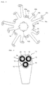
- Figure 4 is a front view of the electric razor according to the present invention; and
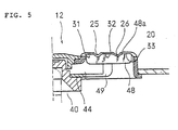
- Figure 5 is a sectional view illustrating the relationship between the cutter of another type of internal cutting member and the external cutting members.
- Turning now to the drawings, as shown in Figure 4, three external cutting members (or shear plates) 12 are disposed in the form of an inverted triangle on the external
cutting member mount 11 which is at the upper portion of the casing of anelectric razor 10. - As shown in Figure 2, the external cutting member is a shallow cylinder with an integral top. At the center of the round
external cutting member 12, acenter cover 18 is fixed. The head of adrive transmission block 16 that is fixed to the center of aninternal cutting member 40 is inserted in thecenter cover 18. The circumferential edge on the open side (or the underside) of theexternal cutting member 12 is provided with anoutward flange 13. Theflange 13 prevents theexternal cutting member 12 from coming out of the casing of therazor 10 after it is fitted into a throughhole 11a from inside of the externalcutting member mount 11. - The area not covered by the
center cover 18 is a shavingsurface 20 that comes into contact with the skin when shaving is performed. The shavingsurface 20 is concentrically divided into three circular shaving sections by grooves. Starting from the section closest to the center of theshaving surface 20, the three sections are aninnermost shaving section 21, anintermediate shaving section 22, and anoutermost shaving section 23. These shaving sections are divided (or partitioned) by concentriccircular partition grooves grooves - Each of the partition grooves protrudes to the rear of the
external cutting member 12, and the rear of theshaving sections innermost track 31, anintermediate track 32, and anoutermost track 33, into which the cutters of the internal cutting member 40 (described below) are fitted respectively. - The shaving
surface 20 is provided with uneven length slits that cross theshaving sections - There are three types of slits which are opened substantially in the radial direction. The slits differ in length so that they correspond to the number of
circular shaving sections - The
first slits 24a are laid out rectilinearly and cross not only all threeshaving sections partition grooves - The second slits 24b are opened between adjacent
first slits 24a, and they are laid out to cross the innermost andintermediate shaving sections partition groove 26. - The
third slits 24c are opened between an adjacentfirst slit 24a and second slit 24b, crossing only theoutermost shaving section 23. Thus, they are the shortest among the three. - These
slits entire shaving surface 20 with a predetermined interval. The ratio of the number of the slits on each one of theshaving sections innermost shaving section 21 is set as 1. - When the surface areas of the three shaving sections are compared with each other, the
innermost shaving section 21 on the center side is the smallest, and the surface area increases as the location of the shaving section comes closer to the outer side. Accordingly, a larger number of slits are formed on the shaving sections located to the outer side. - A description of the internal cutting member that is used together with the outer cutting member described above will be provided below with reference to Figures 2 and 3.
- The
internal cutting member 40 is provided with three rows of cutters, namely,innermost cutters 42a,intermediate cutters 42b andoutermost cutters 42c. These cutters differ in position from the center of theinner cutting member 40 in view of thearms cutters arms circular tracks external cutting member 12. - More specifically, with regard to the internal cutting member, the
drive transmission block 16 is fixed at the center of thecircular plate 44 which is a main body of theinternal cutting member 40. Thisdrive transmission block 16 has a guidingunit 16A and a drive transmission unit 16B. - The guiding
unit 16A protrudes above thecircular plate 44, and the drive transmission unit 16B protrudes downwardly therefrom. In addition, the guidingunit 16A is inserted and guided into the internal depression of thecenter cover 18, and the drive transmission unit 16B is formed with a conical lead-in recess into which the head of adrive shaft 15 for transmitting power from a driving power source (not shown) is fitted. Also, the drive transmission unit 16B has afitting portion 16d that is above the guidingportion 16c. Theflat head portion 15a at the upper end of thedrive shaft 15 fits in thefitting portion 16d. - From the periphery of the
circular plate 44, arms of different or uneven length for mounting thecutters 42a (shortest), 42b (intermediate) and 42c (longest) are extended at regular intervals. - The
innermost cutters 42a are located at the position closest to the center and provided on theshortest arms 46a in a form so as to rise from thearms 46a. Theinnermost cutters 42a are fitted and rotated in the innermostcircular track 31. - The
intermediate cutters 42b are provided in a form so as to rise from the tip end of the arms 46b, which are of an intermediate length compared to the other arms. Thecutters 42b are fitted into the intermediatecircular track 32. - The
outermost cutters 42c are provided in a form so as to rise from the tip end of thearms 46c, which are the longest compared to the other arms. Thecutters 42c are fitted and rotated in the outermostcircular track 33 located in the outermost portion of theexternal cutting member 12. - Figure 5 shows a different type of internal cutting member for use in the present invention.
- The cutter 48 (only one is shown) of the
internal cutting member 40 in Figure 5 has a width sufficient for sliding along the inner surfaces of the three circular tracks of theexternal cutting member 12. Thecutter 48 is provided at the tip of anarm 49 extending from thecircular plate 44 of theinternal cutting member 40. - The
cutter 48 has acutting edge 48a on its upper edge so as to slide along the inner surfaces of thecircular tracks partition grooves partition grooves partition grooves cutter 48 shown in Figure 5 has a wave cutting edge, and a plurality of cutters of this shape are provided on theinternal cutting member 40 at regular intervals by way ofarms 49. - In this embodiment, the cutter has a width that can cover the entire inner (or rear) surface of the shaving
surface 20. However, the width may be set so as to be sufficient to span at least one of thepartition grooves circular tracks external cutting member 12 or covers only thecircular tracks external cutting member 12. In this case, respective cutters may be supported by arms that differ in length and are bent upwardly (in the drawing) from thecircular plate 44. - With the use of the internal cutting member that has cutters as shown in Figure 5, longer hair that enters through the slits opened in the
partition grooves cutting edge 48a that is formed for the entire width of thecutter 48. The hair that has been cut in thepartition grooves surface 20. - Though the shaving
surface 20 is divided into three (or triple) concentric circular shaving sections in the foregoing embodiments, the external cutting member can have, for example, quadruple or quintuple concentric circular shaving sections. In those cases, the internal cutting member has four or five rows of cutters on uneven length arms extending outwardly from the internal cutting member. In addition, the difference in the length of the slits can depend upon the number of shaving sections and circular tracks. - In addition, though the invention has been described in various ways in relation to its most preferable embodiments, it should be understood that the present invention is not limited to the embodiments described above, and various changes and modifications may be made in the invention without departing from the scope of the invention as defined on the appended claims. Such includes the cutters of the internal cutting member being in various different shapes as far as they can fit in the circular tracks of the external cutting member.
- As described above, the electric razor according to the present invention has slits opened in the partition grooves as well as in the concentric circular shaving sections of the surface of each one of the external cutting members. Therefore, it can be kept in a sanitary condition since pieces of hair and the oil that is secreted from the skin are hardly accumulated in the partition grooves. Furthermore, since the partition grooves are U- or V-shaped in a cross section, the accumulation of pieces of hair and oil is more efficiently avoided.
- Also, because the slits are opened in the partition grooves and the cutters are provided so as to cut the hair led in through the slits of the partition grooves, a large surface area can be secured for shaving the hair.
- In addition, since the skin is stretched out by the inner and outer surfaces of the partition grooves, a deep shave is possible. Furthermore, with the use of the electric razor of the present invention, the hair, that would have been impossible to be brought in through the slits of conventional razors in which the hair merely comes into close contact with the shaving surfaces, is first cut when brought into the slits of the partition grooves, and then further cut on the shaving surface that comes into close contact with the skin. Thus, a very clean cut of the hair is obtained. In addition, with partition grooves in a U-shape or V-shape, the hair can be drawn in more smoothly.
Claims (8)
- An electric razor comprising a plurality of external cutting members (12) each having a round top divided into three concentric circular shaving sections (21,22,23), the rear surfaces of said three shaving sections (21,22,23) being defined as circular tracks (31,32,33), and first and second slits (24a,24b) for hair entry opened on said round top at predetermined intervals in a circumferential direction of said external cutting member (12), each one of said second slits (24b) crossing the outer two shaving sections (22,23), and a plurality of internal cutting members (40) each being provided with cutters (42a,b,c;48) at ends of outwardly extending arms (46a,b,c;49), said cutters (42a,b,c;48) fitting in said three circular tracks (31,32,33) of said external cutting member (12); characterized in that said three shaving sections (21,22,23) are divided by two circular grooves (25,26) formed concentrically with a center of said external cutting member (12), in that said first slits (24a) are opened so as to cross said three shaving sections (21,22,23) and said two circular grooves (25,26), in that said second slits (24b) are opened between said first slits (24a), and in that each external cutting member (12) has third slits (24c) for hair entry opened at predetermined intervals in a circumferential direction of said external cutting member (12), each one of said third slits (24c) being opened between adjacent first slits (24a) and second slits (24b) and crossing only the outermost shaving section (23).
- An electric razor according to claim 1, wherein each one of said circular grooves (25,26) is formed to have a narrowed bottom.
- An electric razor according to claim 2, wherein each one of said circular grooves (25,26) has a U-shaped cross section.
- An electric razor according to claim 2, wherein each one of said circular grooves (25,26) has a V-shaped cross section.
- An electric razor according to any one of claims 1 to 4, wherein each internal cutting member (40) has a plurality of arms (49) extending outwardly and cutters (48) at ends of said arms (49), each one of said cutters (48) having a cutting edge (48a) which has a width equal to the width of the rear surface of said shaving surface (20).
- An electric razor according to claim 5, wherein said cutting edge (48a) has a wave shape so as to conform with the configuration of said rear surface of said shaving surface (20).
- An electric razor according to any one of claims 1 to 4, wherein said arms (46a,b,c) extend outwardly in three different lengths.
- An electric razor according to any one of claims 1 to 7, wherein said slits (24a,b,c) are provided so that inwardly extending imaginary lines of said slits (24a,b,c) do not intersect a center of said respective external cutting member (12).
Applications Claiming Priority (2)
| Application Number | Priority Date | Filing Date | Title |
|---|---|---|---|
| JP12569492 | 1992-04-17 | ||
| JP125694/92 | 1992-04-17 |
Publications (2)
| Publication Number | Publication Date |
|---|---|
| EP0566292A1 EP0566292A1 (en) | 1993-10-20 |
| EP0566292B1 true EP0566292B1 (en) | 1997-07-16 |
Family
ID=14916393
Family Applications (1)
| Application Number | Title | Priority Date | Filing Date |
|---|---|---|---|
| EP93302643A Expired - Lifetime EP0566292B1 (en) | 1992-04-17 | 1993-04-05 | Electric razor |
Country Status (5)
| Country | Link |
|---|---|
| US (1) | US5329702A (en) |
| EP (1) | EP0566292B1 (en) |
| AT (1) | ATE155384T1 (en) |
| CA (1) | CA2092892C (en) |
| DE (1) | DE69312149T2 (en) |
Families Citing this family (20)
| Publication number | Priority date | Publication date | Assignee | Title |
|---|---|---|---|---|
| USD405921S (en) | 1993-06-11 | 1999-02-16 | Izumi Products Company | Cutter for electric shaver |
| EP0918599B1 (en) * | 1997-02-19 | 2003-04-23 | Koninklijke Philips Electronics N.V. | Shaving apparatus |
| AUPO592297A0 (en) | 1997-03-27 | 1997-04-24 | Parke, Terrence James | A rotary cutting device having adjustable tension |
| JPH114980A (en) * | 1997-06-17 | 1999-01-12 | Izumi Prod Co | Electric shaver |
| JP4519219B2 (en) * | 1999-06-21 | 2010-08-04 | 株式会社泉精器製作所 | Rotary electric razor |
| JP4338422B2 (en) * | 2002-04-18 | 2009-10-07 | 株式会社泉精器製作所 | Inner blade unit of rotary electric razor |
| US8245404B2 (en) * | 2004-11-01 | 2012-08-21 | Koninklijke Philips Electronics N.A. | Inner cutter with cutter blades at different radii, method for manufacturing such unit, shaver head and rotary shaver provided therewith |
| EP1827773B1 (en) * | 2004-11-01 | 2009-06-03 | Koninklijke Philips Electronics N.V. | Cutter member for a rotary shaver, and rotary shaver provided therwith |
| JP2006218219A (en) * | 2005-02-14 | 2006-08-24 | Izumi Products Co | Rotary type electric razor |
| JP2006218217A (en) * | 2005-02-14 | 2006-08-24 | Izumi Products Co | Rotary type electric razor |
| EP1927441A1 (en) * | 2006-11-28 | 2008-06-04 | Koninklijke Philips Electronics N.V. | Cap having a comfort profile, which is intended to be applied in a shaving head of a shaving apparatus |
| JP5578724B2 (en) * | 2010-11-08 | 2014-08-27 | 株式会社泉精器製作所 | Rotary electric razor |
| JP5649213B2 (en) * | 2010-11-08 | 2015-01-07 | 株式会社泉精器製作所 | Electric razor outer blade and inner blade manufacturing method |
| DE112012004401B4 (en) * | 2011-10-18 | 2015-11-12 | Shanghai Povos Electric Works Co. Ltd. | Rotating electric shaving head |
| US11247351B2 (en) * | 2014-02-24 | 2022-02-15 | Koninklijke Philips N.V. | Rotary shaver comprising a disc-shaped element |
| JP5919455B1 (en) * | 2014-02-24 | 2016-05-18 | コーニンクレッカ フィリップス エヌ ヴェKoninklijke Philips N.V. | Rotary shaver with disc-shaped element |
| JP6712849B2 (en) | 2015-11-02 | 2020-06-24 | マクセルイズミ株式会社 | Rotary electric razor |
| WO2018223682A1 (en) * | 2017-06-05 | 2018-12-13 | 黄勇辉 | Novel rotary shaver |
| EP3736092A1 (en) * | 2019-05-08 | 2020-11-11 | Koninklijke Philips N.V. | Method of manufacturing a guard element for use in a hair-cutting unit |
| CN113172668A (en) * | 2021-05-21 | 2021-07-27 | 中山市小石陶瓷刀片有限公司 | Shaver circular knife net |
Family Cites Families (13)
| Publication number | Priority date | Publication date | Assignee | Title |
|---|---|---|---|---|
| NL59161C (en) * | 1942-03-18 | |||
| GB598664A (en) * | 1944-03-08 | 1948-02-24 | Hermann Konrad S A | Razor |
| GB615670A (en) * | 1945-07-02 | 1949-01-10 | Gear Grinding Mach Co | One-way clutch and method of forming the same |
| CH290390A (en) * | 1948-12-06 | 1953-04-30 | Konrad Hermann | Mechanical razor. |
| NL296894A (en) * | 1963-08-20 | |||
| NL6612851A (en) * | 1966-09-13 | 1968-03-14 | ||
| NL6812448A (en) * | 1968-08-31 | 1970-03-03 | ||
| NL7108535A (en) * | 1971-06-21 | 1972-12-27 | ||
| DE2342677C2 (en) * | 1972-09-13 | 1982-01-14 | Matsushita Electric Works Ltd., Kadoma, Osaka | Shaving comb film for the shaving head of an electric dry shaver |
| GB2057333B (en) * | 1979-08-07 | 1982-12-15 | Matsushita Electric Works Ltd | Shaving blade assembly |
| JPS5793080A (en) * | 1980-11-29 | 1982-06-09 | Matsushita Electric Works Ltd | Rotary type electric razor |
| JPS615868A (en) * | 1984-06-20 | 1986-01-11 | 松下電工株式会社 | Outer blade of electric razor |
| NL8900071A (en) * | 1989-01-12 | 1990-08-01 | Philips Nv | SHAVER. |
-
1993
- 1993-03-03 US US08/025,971 patent/US5329702A/en not_active Expired - Lifetime
- 1993-03-29 CA CA002092892A patent/CA2092892C/en not_active Expired - Lifetime
- 1993-04-05 AT AT93302643T patent/ATE155384T1/en not_active IP Right Cessation
- 1993-04-05 EP EP93302643A patent/EP0566292B1/en not_active Expired - Lifetime
- 1993-04-05 DE DE69312149T patent/DE69312149T2/en not_active Expired - Fee Related
Also Published As
| Publication number | Publication date |
|---|---|
| DE69312149D1 (en) | 1997-08-21 |
| MX9302216A (en) | 1998-05-31 |
| DE69312149T2 (en) | 1998-02-05 |
| CA2092892C (en) | 1998-05-19 |
| HK1012305A1 (en) | 1999-07-30 |
| CA2092892A1 (en) | 1993-10-18 |
| US5329702A (en) | 1994-07-19 |
| ATE155384T1 (en) | 1997-08-15 |
| EP0566292A1 (en) | 1993-10-20 |
Similar Documents
| Publication | Publication Date | Title |
|---|---|---|
| US5329702A (en) | Electric razor | |
| EP0566234B1 (en) | Electric razor | |
| EP2158067B1 (en) | A shaving apparatus, a cutting unit and a shaving head | |
| EP1537964B1 (en) | Razor heads with intermediate guard elements | |
| EP1930137B1 (en) | Shaving foil for a dry shaver | |
| KR100913519B1 (en) | Dry shaver | |
| US6199282B1 (en) | Electric shaver | |
| US4393586A (en) | Shaving blade assembly for rotary type electric shaver | |
| CN100546777C (en) | rotary electric shaver | |
| US8061040B2 (en) | Cutter blade assembly and dry shaver for variable height of cut | |
| EP0652086A1 (en) | Shaving apparatus | |
| CN114829093A (en) | Guard for a depilation device | |
| EP1819488B1 (en) | Cutter unit for a rotary shaver and rotary shaver provided therewith | |
| EP1827773B1 (en) | Cutter member for a rotary shaver, and rotary shaver provided therwith | |
| HK1012305B (en) | Electric razor | |
| HK1012609A (en) | Electric razor | |
| JPH06218156A (en) | Shaver device | |
| MXPA05001908A (en) | An electric shaver. | |
| JP3514483B2 (en) | Electric razor | |
| NL8802311A (en) | SHAVER. | |
| MXPA93002216A (en) | Electric shave machine | |
| EP1452282A1 (en) | A rotary type electric shaver | |
| US5329700A (en) | Flexible razor unit employing embossed blades | |
| HK1017231B (en) | Electric razor | |
| JPS6324714B2 (en) |
Legal Events
| Date | Code | Title | Description |
|---|---|---|---|
| PUAI | Public reference made under article 153(3) epc to a published international application that has entered the european phase |
Free format text: ORIGINAL CODE: 0009012 |
|
| AK | Designated contracting states |
Kind code of ref document: A1 Designated state(s): AT BE CH DE DK ES FR GB GR IE IT LI LU MC NL PT SE |
|
| 17P | Request for examination filed |
Effective date: 19940103 |
|
| 17Q | First examination report despatched |
Effective date: 19951027 |
|
| GRAG | Despatch of communication of intention to grant |
Free format text: ORIGINAL CODE: EPIDOS AGRA |
|
| GRAH | Despatch of communication of intention to grant a patent |
Free format text: ORIGINAL CODE: EPIDOS IGRA |
|
| GRAH | Despatch of communication of intention to grant a patent |
Free format text: ORIGINAL CODE: EPIDOS IGRA |
|
| GRAH | Despatch of communication of intention to grant a patent |
Free format text: ORIGINAL CODE: EPIDOS IGRA |
|
| GRAA | (expected) grant |
Free format text: ORIGINAL CODE: 0009210 |
|
| AK | Designated contracting states |
Kind code of ref document: B1 Designated state(s): AT BE CH DE DK ES FR GB GR IE IT LI LU MC NL PT SE |
|
| PG25 | Lapsed in a contracting state [announced via postgrant information from national office to epo] |
Ref country code: LI Free format text: LAPSE BECAUSE OF FAILURE TO SUBMIT A TRANSLATION OF THE DESCRIPTION OR TO PAY THE FEE WITHIN THE PRESCRIBED TIME-LIMIT Effective date: 19970716 Ref country code: GR Free format text: LAPSE BECAUSE OF FAILURE TO SUBMIT A TRANSLATION OF THE DESCRIPTION OR TO PAY THE FEE WITHIN THE PRESCRIBED TIME-LIMIT Effective date: 19970716 Ref country code: ES Free format text: THE PATENT HAS BEEN ANNULLED BY A DECISION OF A NATIONAL AUTHORITY Effective date: 19970716 Ref country code: DK Effective date: 19970716 Ref country code: CH Free format text: LAPSE BECAUSE OF FAILURE TO SUBMIT A TRANSLATION OF THE DESCRIPTION OR TO PAY THE FEE WITHIN THE PRESCRIBED TIME-LIMIT Effective date: 19970716 Ref country code: BE Effective date: 19970716 Ref country code: AT Effective date: 19970716 |
|
| REF | Corresponds to: |
Ref document number: 155384 Country of ref document: AT Date of ref document: 19970815 Kind code of ref document: T |
|
| REG | Reference to a national code |
Ref country code: CH Ref legal event code: EP |
|
| REF | Corresponds to: |
Ref document number: 69312149 Country of ref document: DE Date of ref document: 19970821 |
|
| ITF | It: translation for a ep patent filed | ||
| PG25 | Lapsed in a contracting state [announced via postgrant information from national office to epo] |
Ref country code: SE Effective date: 19971016 |
|
| PG25 | Lapsed in a contracting state [announced via postgrant information from national office to epo] |
Ref country code: PT Effective date: 19971022 |
|
| ET | Fr: translation filed | ||
| REG | Reference to a national code |
Ref country code: CH Ref legal event code: PL |
|
| PG25 | Lapsed in a contracting state [announced via postgrant information from national office to epo] |
Ref country code: LU Free format text: LAPSE BECAUSE OF NON-PAYMENT OF DUE FEES Effective date: 19980405 Ref country code: IE Free format text: LAPSE BECAUSE OF NON-PAYMENT OF DUE FEES Effective date: 19980405 |
|
| PLBE | No opposition filed within time limit |
Free format text: ORIGINAL CODE: 0009261 |
|
| STAA | Information on the status of an ep patent application or granted ep patent |
Free format text: STATUS: NO OPPOSITION FILED WITHIN TIME LIMIT |
|
| 26N | No opposition filed | ||
| PG25 | Lapsed in a contracting state [announced via postgrant information from national office to epo] |
Ref country code: MC Free format text: LAPSE BECAUSE OF NON-PAYMENT OF DUE FEES Effective date: 19981031 |
|
| REG | Reference to a national code |
Ref country code: GB Ref legal event code: IF02 |
|
| REG | Reference to a national code |
Ref country code: HK Ref legal event code: WD Ref document number: 1012609 Country of ref document: HK |
|
| PGFP | Annual fee paid to national office [announced via postgrant information from national office to epo] |
Ref country code: NL Payment date: 20070430 Year of fee payment: 15 Ref country code: DE Payment date: 20070430 Year of fee payment: 15 |
|
| PGFP | Annual fee paid to national office [announced via postgrant information from national office to epo] |
Ref country code: GB Payment date: 20070427 Year of fee payment: 15 |
|
| PGFP | Annual fee paid to national office [announced via postgrant information from national office to epo] |
Ref country code: IT Payment date: 20070629 Year of fee payment: 15 |
|
| PGFP | Annual fee paid to national office [announced via postgrant information from national office to epo] |
Ref country code: FR Payment date: 20070430 Year of fee payment: 15 |
|
| GBPC | Gb: european patent ceased through non-payment of renewal fee |
Effective date: 20080405 |
|
| NLV4 | Nl: lapsed or anulled due to non-payment of the annual fee |
Effective date: 20081101 |
|
| PG25 | Lapsed in a contracting state [announced via postgrant information from national office to epo] |
Ref country code: NL Free format text: LAPSE BECAUSE OF NON-PAYMENT OF DUE FEES Effective date: 20081101 Ref country code: DE Free format text: LAPSE BECAUSE OF NON-PAYMENT OF DUE FEES Effective date: 20081101 |
|
| REG | Reference to a national code |
Ref country code: FR Ref legal event code: ST Effective date: 20081231 |
|
| PG25 | Lapsed in a contracting state [announced via postgrant information from national office to epo] |
Ref country code: FR Free format text: LAPSE BECAUSE OF NON-PAYMENT OF DUE FEES Effective date: 20080430 |
|
| PG25 | Lapsed in a contracting state [announced via postgrant information from national office to epo] |
Ref country code: GB Free format text: LAPSE BECAUSE OF NON-PAYMENT OF DUE FEES Effective date: 20080405 |
|
| PG25 | Lapsed in a contracting state [announced via postgrant information from national office to epo] |
Ref country code: IT Free format text: LAPSE BECAUSE OF NON-PAYMENT OF DUE FEES Effective date: 20080405 |