EP0566008B1 - Air operated disc brake - Google Patents
Air operated disc brake Download PDFInfo
- Publication number
- EP0566008B1 EP0566008B1 EP93105709A EP93105709A EP0566008B1 EP 0566008 B1 EP0566008 B1 EP 0566008B1 EP 93105709 A EP93105709 A EP 93105709A EP 93105709 A EP93105709 A EP 93105709A EP 0566008 B1 EP0566008 B1 EP 0566008B1
- Authority
- EP
- European Patent Office
- Prior art keywords
- brake
- disk
- compressed
- adjusting
- caliper
- Prior art date
- Legal status (The legal status is an assumption and is not a legal conclusion. Google has not performed a legal analysis and makes no representation as to the accuracy of the status listed.)
- Revoked
Links
Images


Classifications
-
- F—MECHANICAL ENGINEERING; LIGHTING; HEATING; WEAPONS; BLASTING
- F16—ENGINEERING ELEMENTS AND UNITS; GENERAL MEASURES FOR PRODUCING AND MAINTAINING EFFECTIVE FUNCTIONING OF MACHINES OR INSTALLATIONS; THERMAL INSULATION IN GENERAL
- F16D—COUPLINGS FOR TRANSMITTING ROTATION; CLUTCHES; BRAKES
- F16D65/00—Parts or details
- F16D65/14—Actuating mechanisms for brakes; Means for initiating operation at a predetermined position
- F16D65/16—Actuating mechanisms for brakes; Means for initiating operation at a predetermined position arranged in or on the brake
- F16D65/18—Actuating mechanisms for brakes; Means for initiating operation at a predetermined position arranged in or on the brake adapted for drawing members together, e.g. for disc brakes
- F16D65/183—Actuating mechanisms for brakes; Means for initiating operation at a predetermined position arranged in or on the brake adapted for drawing members together, e.g. for disc brakes with force-transmitting members arranged side by side acting on a spot type force-applying member
-
- F—MECHANICAL ENGINEERING; LIGHTING; HEATING; WEAPONS; BLASTING
- F16—ENGINEERING ELEMENTS AND UNITS; GENERAL MEASURES FOR PRODUCING AND MAINTAINING EFFECTIVE FUNCTIONING OF MACHINES OR INSTALLATIONS; THERMAL INSULATION IN GENERAL
- F16D—COUPLINGS FOR TRANSMITTING ROTATION; CLUTCHES; BRAKES
- F16D65/00—Parts or details
- F16D65/38—Slack adjusters
- F16D65/40—Slack adjusters mechanical
- F16D65/52—Slack adjusters mechanical self-acting in one direction for adjusting excessive play
- F16D65/56—Slack adjusters mechanical self-acting in one direction for adjusting excessive play with screw-thread and nut
- F16D65/567—Slack adjusters mechanical self-acting in one direction for adjusting excessive play with screw-thread and nut for mounting on a disc brake
- F16D65/568—Slack adjusters mechanical self-acting in one direction for adjusting excessive play with screw-thread and nut for mounting on a disc brake for synchronous adjustment of actuators arranged in parallel
-
- F—MECHANICAL ENGINEERING; LIGHTING; HEATING; WEAPONS; BLASTING
- F16—ENGINEERING ELEMENTS AND UNITS; GENERAL MEASURES FOR PRODUCING AND MAINTAINING EFFECTIVE FUNCTIONING OF MACHINES OR INSTALLATIONS; THERMAL INSULATION IN GENERAL
- F16D—COUPLINGS FOR TRANSMITTING ROTATION; CLUTCHES; BRAKES
- F16D2121/00—Type of actuator operation force
- F16D2121/14—Mechanical
-
- F—MECHANICAL ENGINEERING; LIGHTING; HEATING; WEAPONS; BLASTING
- F16—ENGINEERING ELEMENTS AND UNITS; GENERAL MEASURES FOR PRODUCING AND MAINTAINING EFFECTIVE FUNCTIONING OF MACHINES OR INSTALLATIONS; THERMAL INSULATION IN GENERAL
- F16D—COUPLINGS FOR TRANSMITTING ROTATION; CLUTCHES; BRAKES
- F16D2125/00—Components of actuators
- F16D2125/18—Mechanical mechanisms
- F16D2125/20—Mechanical mechanisms converting rotation to linear movement or vice versa
- F16D2125/22—Mechanical mechanisms converting rotation to linear movement or vice versa acting transversely to the axis of rotation
- F16D2125/26—Cranks
-
- F—MECHANICAL ENGINEERING; LIGHTING; HEATING; WEAPONS; BLASTING
- F16—ENGINEERING ELEMENTS AND UNITS; GENERAL MEASURES FOR PRODUCING AND MAINTAINING EFFECTIVE FUNCTIONING OF MACHINES OR INSTALLATIONS; THERMAL INSULATION IN GENERAL
- F16D—COUPLINGS FOR TRANSMITTING ROTATION; CLUTCHES; BRAKES
- F16D2125/00—Components of actuators
- F16D2125/18—Mechanical mechanisms
- F16D2125/58—Mechanical mechanisms transmitting linear movement
- F16D2125/64—Levers
Definitions
- the invention relates to a compressed air-operated disc brake according to the preamble of claim 1, which is provided in particular for road vehicles and preferably for commercial vehicles.
- Compressed air or pneumatic disc brakes of the generic type are known, for example, from DE-OS 37 16 202 and from unpublished DE-OS 40 32 885.
- a brake disc is encompassed by a brake caliper displaceably mounted in the axial direction, with a compressed air-operated application device being arranged on one side of the brake caliper, upon actuation of which a brake shoe located on this side of the brake disc is pressed against it, causing the brake caliper to move due to the Reaction forces shifts in the opposite direction and thereby also presses a brake shoe on the opposite side against the brake disc.
- the application device has a rotary lever as the actuating element, which is pivotably mounted about an axis of rotation running parallel to the plane of the brake disc.
- the rotary lever here lies on its side facing the brake disc by means of an eccentric approximately longitudinally against a cross-piece extending parallel to the axis of rotation, which is displaceably guided with respect to the brake disc and in which at least one adjusting spindle having an external thread is screwed adjustably in a respectively assigned internal thread of the cross-beam is, the adjusting spindle over a on her Brake disc-side end of the pressure piece acts on the brake side of the brake caliper, which is slidably mounted with respect to the brake disc.
- an adjusting device is provided which is non-rotatably coupled to the adjusting spindle and each time the rotary lever is actuated, the adjusting spindle then rotates through a certain angle if the Brake shoe is not yet in contact with the brake disc after overcoming the target air gap.
- the adjustment device has, among other things, functionally essential parts. a freewheel and a slip clutch.
- the adjusting device has at its end remote from the brake disc, for example in the form of a hexagon, which, by means of a suitable socket wrench, enables the adjusting device (and thus the adjusting spindle coupled thereto) to be rotated counter to the adjusting direction.
- the invention has for its object to develop a compressed air operated disc brake according to the preamble of claim 1 such that a brake failure due to improper implementation of the pad change can be largely avoided.
- the separating device in which the torque transmission path is formed by a shaft formed with the rotary head, the separating device is formed as a notch in the region of the shaft adjoining the rotary head.
- This design of the separating device can be implemented with little effort, in particular in the case of a predetermined breaking point designed as a notch, and moreover allows a very exact setting of the desired limit torque, which is of course selected taking into account the maximum load capacity of the functional elements of the adjusting device.
- a (internally ventilated) brake disc 1 which is fastened to an axle of a commercial vehicle, which is not specified in more detail, is encompassed by a brake caliper 2.
- the brake caliper 2 is mounted on the vehicle in an axially displaceable manner with respect to the brake disc 1 by means of a rigid guide bearing 52 and by means of a compensating bearing 51. Otherwise, the structure and function of the brake caliper are known, so that a further explanation is unnecessary.
- a (two-spindle) application device schematically designated by the reference number 3 is arranged.
- a substantially semicircular pivot bearing 30 is provided, the axis of rotation of which runs parallel to the level of the brake disc 1 and which receives the correspondingly rounded region of a rotary lever 4, so that the rotary lever 4 can be pivoted parallel to the level of the brake disc 1.
- a brake cylinder 40 which is only shown schematically, is provided, which engages with a piston in a suitably shaped recess in an actuating arm 4a of the rotary lever 4.
- the actuating arm 4a of the rotary lever 4 is consequently moved from its rest position into the position indicated in broken lines in FIG. 1. It should be noted that the actuation of the rotary lever 4 can of course also take place via a brake linkage, so that the brake cylinder 40 can optionally be placed at a different location if the available installation space for the disc brake or its application device is limited.
- the side of the rotary lever 4 facing away from the half-shell-shaped rotary bearing 30 is coupled via an eccentric 6 serving as a cam to a cross member 7 which is located within the Brake caliper 2 extends substantially parallel to the axis of rotation of the brake disc 1 and is slidably mounted in this plane.
- the cross member 7 At its end facing the brake disc 1, the cross member 7 has a blind hole-like recess, which is surrounded by a tubular extension projecting in the direction of the brake disc 1.
- This approach of the cross member 7 is in a corresponding recess of the brake caliper 2 perpendicular to the plane of the brake disc 1 while maintaining such a play that the cross member 7 can perform slight pivoting movements in the plane of the drawing.
- a spiral spring 78 is arranged within the recess and is clamped between the cross member 7 and the end of the brake caliper 2 facing the brake disc 1 and thereby prestresses the cross member 7 towards the rotary lever 4.
- the cross member 7 has on both sides a bore provided with an internal thread, in each of which an adjusting spindle 72 or 73 is adjustably screwed, the external thread designated in FIG a correspondingly shaped internal thread of the cross member 7 is guided.
- a conically widening pressure piece 70 or 71 is fastened. Since the two adjusting spindles 72 and 73 extend perpendicular to the plane of the brake disc 1 due to their arrangement in the crossmember 7, the pressure pieces 70 and 71 rest with their flat ends on a brake shoe 10.
- the brake shoe 10 is guided in particular in the circumferential direction to the brake disc 1 by means of brackets (not shown) displaceable transversely to the brake disk 1, wherein the brackets can either be assigned to the brake caliper 2 or a brake carrier.
- An adjusting device 74 is arranged in the interior of the adjusting spindle 72 and is rotationally fixed as a result of an axial toothing is coupled to the adjusting spindle 72 and is displaceable in the axial direction.
- the adjusting device 74 is rotated by a certain angular amount each time the rotary lever 4 is actuated, which ensures continuous readjustment of the brake.
- a gear engages in a corresponding axial toothing of the opposite adjusting spindle 73, which gear is coupled via a shaft to a synchronization device 75, which rotates the internal gear and thus the spindle 73 synchronously with the adjusting device 74. This ensures that the pressure piece 71 is adjusted synchronously with the pressure piece 70.
- the adjusting spindle is arranged, for example, in the middle of the cross member 7, while the eccentric 6 and the bearing of the cross member 7 having the compression spring are each produced in duplicate are provided on both sides of the central adjusting spindle.
- the adjusting device 74 has on its upper, i.e. End facing away from the brake disc on a turret in the form of a hexagon 19; this is coupled via a shaft 16 to the inner functional elements, which are only indicated schematically, such that turning the hexagon in the counter-tightening direction causes the adjusting spindle in FIG. 3 to move back up to its starting position, so that a new brake shoe 10 is installed can be.
- the cross member 7 is therefore pressed against the biasing force of a coil spring 78 by this distance to the brake disc 1.
- the pressure pieces 70 and 71 attached to the crossbeam 7 via the adjusting spindles 72 and 73 consequently press the brake shoe 10 against the brake disk 1 while overcoming the clearance (which in practice is approximately 0.4 mm). If the actuating arm 4a continues to move is pivoted to the left, the brake caliper moves due to the force exerted on the brake disc 1 in FIG. 1 to the right, so that finally the left brake shoe 10 is also pressed against the brake disc 1.
- the adjusting device 74 ensures that the adjusting spindles 72 and 73 rotate until the air gap reaches its desired value. In this way it is ensured that the disc brake remains functional until the brake shoes 10 are completely worn.
- the adjusting spindles 72 and 73 can reach their limit position facing away from the brake disk, in which their rotation is inhibited, as a result of which a strong moment is built up between the adjusting spindle and the adjusting device which is coupled to it in a rotationally fixed manner; when this moment is in the form of a separating device shown in FIG. 3 and formed in a shaft 16 connecting the hexagon 19 to the functional elements a predetermined breaking point SB exceeds the predetermined limit value, the shaft 16 breaks at the predetermined breaking point SB, so that destruction of the parts necessary for the safe operation of the brake can be reliably prevented.
- the predetermined breaking point SB can be produced in a simple manner by means of a notch in the shaft or another material weakening.
- the predetermined breaking point SB in the embodiment shown is expediently arranged outside the housing cover of the application device 3; this ensures that all parts necessary for the operation of the brake, in particular also a link chain of the synchronization device 75, continue to be operated correctly despite the response of the predetermined breaking point SB.
- the separating device As a slip clutch which responds at a predetermined torque.
- the force transmission takes place by means of a rotatably mounted lever 4, which acts on a crossbar 7 via an eccentric;
- the principle of the invention can of course also be used in other application devices, for example in those in which the force transmission takes place by means of an expansion wedge or a ball ramp.
- the invention is not limited to the embodiments of the adjusting spindle and adjusting device shown; the separating device can rather be used with all adjusting elements whose axial position relative to the brake disc increases with increasing Pad wear is changed by a suitable drive device.
Description
Die Erfindung bezieht sich auf eine druckluftbetätigte Scheibenbremse gemäß dem Oberbegriff des Anspruchs 1, die insbesondere für Straßenfahrzeuge und vorzugsweise für Nutzfahrzeuge vorgesehen ist.The invention relates to a compressed air-operated disc brake according to the preamble of
Druckluftbetätigte bzw. pneumatische Scheibenbremsen der gattungsgemäßen Art sind beispielsweise aus der DE-OS 37 16 202 sowie aus der nicht vorveröffentlichten DE-OS 40 32 885 bekannt. Bei diesen bekannten Scheibenbremsen wird eine Bremsscheibe von einem in Axialrichtung verschiebbar gelagerten Bremssattel umfaßt, wobei auf einer Seite des Bremssattels eine druckluftbetätigte Zuspannvorrichtung angeordnet ist, bei deren Betätigung eine auf dieser Seite der Bremsscheibe befindliche Bremsbacke gegen diese gedrückt wird, worauf sich der Bremssattel aufgrund der Reaktionskräfte in Gegenrichtung verschiebt und dadurch eine auf der gegenüberliegenden Seite befindliche Bremsbacke gleichfalls an die Bremsscheibe andrückt.Compressed air or pneumatic disc brakes of the generic type are known, for example, from DE-OS 37 16 202 and from unpublished DE-OS 40 32 885. In these known disc brakes, a brake disc is encompassed by a brake caliper displaceably mounted in the axial direction, with a compressed air-operated application device being arranged on one side of the brake caliper, upon actuation of which a brake shoe located on this side of the brake disc is pressed against it, causing the brake caliper to move due to the Reaction forces shifts in the opposite direction and thereby also presses a brake shoe on the opposite side against the brake disc.
Die Zuspannvorrichtung weist bei diesen bekannten Scheibenbremsen als Betätigungsorgan einen Drehhebel auf, der um eine zur Ebene der Bremsscheibe parallel verlaufende Drehachse schwenkbar gelagert ist. Der Drehhebel liegt hierbei auf seiner der Bremsscheibe zugewandten Seite mittels eines Exzenters etwa längsmittig an einer sich parallel zur Drehachse erstreckenden Traverse an, die bezüglich der Bremsscheibe verschiebbar geführt ist und in der mindestens eine ein Außengewinde aufweisende Stellspindel in einem jeweils zugeordneten Innengewinde der Traverse verstellbar verschraubt ist, wobei die Stellspindel über ein an ihrem bremsscheibenseitigen Ende sitzendes Druckstück auf die zuspannseitig im Bremssattel bezüglich der Bremsscheibe verschiebbar gelagerte Bremsbacke einwirkt.In these known disc brakes, the application device has a rotary lever as the actuating element, which is pivotably mounted about an axis of rotation running parallel to the plane of the brake disc. The rotary lever here lies on its side facing the brake disc by means of an eccentric approximately longitudinally against a cross-piece extending parallel to the axis of rotation, which is displaceably guided with respect to the brake disc and in which at least one adjusting spindle having an external thread is screwed adjustably in a respectively assigned internal thread of the cross-beam is, the adjusting spindle over a on her Brake disc-side end of the pressure piece acts on the brake side of the brake caliper, which is slidably mounted with respect to the brake disc.
Um das Lüftspiel, d.h. den Abstand der Bremsbacken zur Bremsscheibe im unbetätigten Zustand unter Ausgleich der sich durch Abrieb ändernden Belagstärke konstant zu halten, ist eine Nachstelleinrichtung vorgesehen, die mit der Stellspindel drehfest gekoppelt ist und bei jeder Betätigung des Drehhebels die Stellspindel dann um einen bestimmten Winkel dreht, wenn die Bremsbacke nach Überwindung des Soll-Lüftspiels noch nicht an der Bremsscheibe anliegt. Zu diesem Zweck weist die Nachstelleinrichtung als funktionswesentliche Teile u.a. einen Freilauf sowie eine Rutschkupplung auf. Zu näheren Einzelheiten des Aufbaus einer derartigen Nachstelleinrichtung wird im übrigen auf die DE-OS 40 34 165 verwiesen und vollinhaltlich bezug genommen.For the air play, i.e. to keep the distance of the brake shoes to the brake disc in the unactuated state while compensating for the lining thickness that changes due to abrasion, an adjusting device is provided which is non-rotatably coupled to the adjusting spindle and each time the rotary lever is actuated, the adjusting spindle then rotates through a certain angle if the Brake shoe is not yet in contact with the brake disc after overcoming the target air gap. For this purpose, the adjustment device has, among other things, functionally essential parts. a freewheel and a slip clutch. For further details of the construction of such an adjustment device, reference is made to DE-OS 40 34 165 and refer to the full content.
Wenn der Bremsbelag weitgehend abgerieben ist, ist zum Vermeiden eines Bremsenausfalls ein neuer Bremsbelag einzubauen, wozu der Wartungstechniker die Stellspindel(n) wieder in ihre Ausgangslage zurückbringen muß, um ausreichend Platz für den neuen Bremsbelag zu schaffen. Um diesen Rückstellvorgang möglichst einfach zu gestalten, weist die Nachstelleinrichtung an ihrem bremsscheibenabgewandten Ende einen Drehkopf beispielsweise in Form eines Sechskants auf, der mittels eines geeigneten Steckschlüssels ein entsprechendes Drehen der Nachstelleinrichtung (und damit der mit dieser gekoppelten Stellspindel) entgegen der Nachstellrichtung ermöglicht.If the brake pad has largely rubbed off, a new brake pad must be installed to avoid a brake failure, for which the maintenance technician must return the adjusting spindle (s) to their initial position in order to create enough space for the new brake pad. In order to make this resetting process as simple as possible, the adjusting device has at its end remote from the brake disc, for example in the form of a hexagon, which, by means of a suitable socket wrench, enables the adjusting device (and thus the adjusting spindle coupled thereto) to be rotated counter to the adjusting direction.
Hierbei besteht jedoch die Gefahr, daß der Wartungstechniker auch dann noch dreht, wenn die Stellspindel bereits ihren Endanschlag erreicht hat. In diesem Fall wird die Drehung der Stellspindel gehemmt, wodurch zwischen der Stellspindel und der mit ihr drehfest gekoppelten Nachstelleinrichtung ein starkes Moment aufgebaut wird, das ohne weiteres ausreicht, die empfindlichen Funktionsteile der Nachstelleinrichtung zu zerstören. Diese Beschädigung der Nachstelleinrichtung wird jedoch nicht ohne weiteres bemerkt, so daß die Gefahr besteht, daß der Wartungstechniker den Belagwechsel ohne Austausch der beschädigten Nachstelleinrichtung zu Ende führt. Ein Bremsversagen ist in diesem Fall nicht vermeidbar.Here, however, there is a risk that the maintenance technician will still turn even if the adjusting spindle has already reached its end stop. In this case, the rotation of the adjusting spindle is inhibited, which means that between the adjusting spindle and the adjusting device coupled to it in a rotationally fixed manner builds up a strong moment which is easily sufficient to destroy the sensitive functional parts of the adjusting device. However, this damage to the adjusting device is not readily noticed, so that there is a risk that the maintenance technician will finish the pad replacement without replacing the damaged adjusting device. In this case, brake failure cannot be avoided.
Der Erfindung liegt die Aufgabe zugrunde, eine druckluftbetätigte Scheibenbremse gemäß dem Oberbegriff des Anspruchs 1 derart weiterzubilden, daß ein durch eine unsachgemäße Durchführung des Belagwechsels bedingtes Bremsversagen weitgehend vermieden werden kann.The invention has for its object to develop a compressed air operated disc brake according to the preamble of
Diese Aufgabe wird erfindungsgemäß mit den im Kennzeichnungsteil des Anspruchs 1 angegebenen Maßnahmen gelöst.This object is achieved with the measures specified in the characterizing part of
Hierdurch wird erreicht, daß im eingangs genannten Fall einer übermäßigen Betätigung des Drehkopfs der Kraftschluß zu den Funktionselementen der Nachstelleinrichtung unterbrochen wird, so daß eine Beschädigung derselben sicher vermieden wird. Die Funktionssicherheit der Bremse ist daher bei einer solch unsachgemäßen Handhabung selbst dann nicht in Frage gestellt, wenn der Wartungstechniker das Ansprechen der Trenneinrichtung nicht registriert. Lediglich der nachfolgende Belagwechsel ist insoweit erschwert, als das Zurückdrehen der Stellspindeln nunmehr mit wesentlich mehr Aufwand verbunden ist.This ensures that in the case of excessive actuation of the rotary head, the frictional connection to the functional elements of the adjusting device is interrupted, so that damage to the same is reliably avoided. With such improper handling, the functional reliability of the brake is therefore not called into question even if the maintenance technician does not register the response of the separating device. Only the subsequent change of pad is more difficult in that the turning back of the adjusting spindles is now associated with considerably more effort.
Damit beim Ansprechen der erfindungsgemäßen Trenneinrichtung keine Reparatur erforderlich, ist es möglich, diese vermittels einer Rutschkupplung auszubilden.So that no repair is required when the separating device according to the invention responds, it is possible to design it by means of a slip clutch.
Gemäß einer Weiterbildung der Erfindung ist vorgesehen, daß bei einer Scheibenbremse, bei der der Momentenübertragungsweg durch eine mit dem Drehkopf gebildete Welle gebildet ist, die Trenneinrichtung in dem sich an den Drehkopf anschließenden Bereich der Welle als Einkerbung derselben ausgebildet wird. Diese Ausgestaltung der Trenneinrichtung ist insbesondere bei einer als Einkerbung ausgebildeten Sollbruchstelle mit wenig Aufwand zu realisieren und erlaubt zudem eine sehr exakte Einstellung des gewünschten Grenz-Drehmoments, das selbstverständlich unter Berücksichtigung der maximalen Belastbarkeit der Funktionselemente der Nachstelleinrichtung gewählt wird.According to a development of the invention, it is provided that in a disc brake, in which the torque transmission path is formed by a shaft formed with the rotary head, the separating device is formed as a notch in the region of the shaft adjoining the rotary head. This design of the separating device can be implemented with little effort, in particular in the case of a predetermined breaking point designed as a notch, and moreover allows a very exact setting of the desired limit torque, which is of course selected taking into account the maximum load capacity of the functional elements of the adjusting device.
Die Erfindung wird nachstehend anhand der Beschreibung von Ausführungsbeispielen unter Bezugnahme auf die Zeichnung näher erläutert. Es zeigen:
- Fig. 1 anhand eines Querschnitts den schematischen Aufbau der Zuspannvorrichtung;
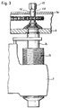
- Fig. 2 einen Längsschnitt der in Fig. 1 gezeigten Zuspannvorrichtung; und
- Fig. 3 ein vergrößertes Detail der Fig.2 zur Erläuterung der Funktionsweise der Sollbruchstelle.
- 1 shows the schematic structure of the application device on the basis of a cross section;
- FIG. 2 shows a longitudinal section of the application device shown in FIG. 1; and
- Fig. 3 is an enlarged detail of Figure 2 to explain the operation of the predetermined breaking point.
Um die der Erfindung zugrundeliegende Problematik zu verdeutlichen, sollen zunächst der prinzipielle Aufbau und die Wirkungsweise der gattungsgemäßen Scheibenbremse und deren Zuspannvorrichtung näher erläutert werden. Obgleich die gezeigte Ausführungsform der Zuspannvorrichtung zwei Spindeln aufweist, sei darauf hingewiesen, daß die Erfindung selbstverständlich auch bei einer einspindeligen Zuspannvorrichtung verwendbar ist.In order to clarify the problem on which the invention is based, the basic structure and mode of operation of the generic disc brake and its application device should first be explained in more detail. Although the embodiment of the clamping device shown has two spindles, it should be pointed out that the invention can of course also be used with a single-spindle clamping device.
Wie aus den Figuren 1 und 2 zu erkennen ist, wird eine (innenbelüftete) Bremsscheibe 1, die an einer nicht näher bezeichneten Achse eines Nutzfahrzeugs befestigt ist, von einem Bremssattel 2 umfaßt. Der Bremssattel 2 ist gemäß Fig. 2 mittels eines starren Führungslagers 52 sowie mittels eines Ausgleichslagers 51 in axialer Verschiebbarkeit bezüglich der Bremsscheibe 1 am Fahrzeug gelagert. Im übrigen sind Aufbau und Funktion des Bremssattels bekannt, so daß sich eine nähere Erläuterung erübrigt.As can be seen from FIGS. 1 and 2, a (internally ventilated)
Auf der in Fig. 1 rechten bzw. der in Fig. 2 unteren Seite der Bremsscheibe 1 ist eine schematisch mit dem Bezugszeichen 3 bezeichnete (zweispindelige) Zuspannvorrichtung angeordnet. Im Bremssattel 2 ist ein im wesentlichen halbkreisförmiges Drehlager 30 vorgesehen, dessen Drehachse parallel zur Ebene der Bremsscheibe 1 verläuft und das den entsprechend abgerundeten Bereich eines Drehhebels 4 aufnimmt, so daß der Drehhebel 4 parallel zur Ebene der Bremsscheibe 1 verschwenkt werden kann. Zur Betätigung des Drehhebels 4 ist ein lediglich schematisch dargestellter Bremszylinder 40 vorgesehen, der mit einem Kolben in eine geeignet geformte Ausnehmung eines Betätigungsarms 4a des Drehhebels 4 eingreift. Wenn der Bremszylinder 40 mit der Druckluft beaufschlagt wird, wird der Betätigungsarm 4a des Drehhebels 4 folglich von seiner Ruheposition in die in Fig. 1 in gestrichelter Darstellung angedeutete Position bewegt. Es sei angemerkt, daß die Betätigung des Drehhebels 4 selbstverständlich auch über ein Bremsgestänge erfolgen kann, so daß der Bremszylinder 40 gegebenenfalls an einem anderen Ort plaziert werden kann, falls der verfügbare Einbauraum für die Scheibenbremse bzw. deren Zuspannvorrichtung begrenzt ist.On the right side in FIG. 1 or the lower side of the
Die dem halbschalenförmigen Drehlager 30 abgewandte Seite des Drehhebels 4 ist über einen als Nocken dienenden Exzenter 6 mit einer Traverse 7 gekoppelt, die sich innerhalb des Bremssattels 2 im wesentlichen parallel zur Drehachse der Bremsscheibe 1 erstreckt und in dieser Ebene verschiebbar gelagert ist. An ihrem der Bremsscheibe 1 zugewandten Ende weist die Traverse 7 eine sacklochartige Ausnehmung auf, die von einem in Richtung zur Bremsscheibe 1 auskragenden, rohrartigen Ansatz umgeben ist. Dieser Ansatz der Traverse 7 ist in einer entsprechenden Ausnehmung des Bremssattels 2 rechtwinklig zur Ebene der Bremsscheibe 1 unter Beibehaltung eines derartigen Spiels schiebegelagert, daß die Traverse 7 geringfügige Schwenkbewegungen in der Zeichnungsebene ausführen kann. Innerhalb der Ausnehmung ist eine Spiralfeder 78 angeordnet, die zwischen die Traverse 7 und das der Bremsscheibe 1 zugewandte Ende des Bremssattels 2 eingespannt ist und dadurch die Traverse 7 zum Drehhebel 4 hin vorspannt.The side of the
Wie insbesondere dem Längsschnitt der Fig. 2 entnehmbar ist, weist die Traverse 7 an beiden Seiten jeweils eine mit einem Innengewinde versehene Bohrung auf, in der jeweils eine Stellspindel 72 bzw. 73 justierbar verschraubt ist, deren in Fig.3 mit 711 bezeichnetes Außengewinde in einem entsprechend geformten Innengewinde der Traverse 7 geführt ist. An dem der Bremsscheibe 1 zugewandten Ende jeder der Stellspindeln 72 und 73 ist ein sich kegelförmig verbreiterndes Druckstück 70 bzw. 71 befestigt. Da sich die beiden Stellspindeln 72 und 73 infolge ihrer Anordnung in der Traverse 7 senkrecht zur Ebene der Bremsscheibe 1 erstrecken, liegen die Druckstücke 70 und 71 mit ihren flachen Enden an einer Bremsbacke 10 an. Die Bremsbacke 10 ist insbesondere in Umfangsrichtung zur Bremsscheibe 1 über nicht gezeigte Halterungen quer zur Bremsscheibe 1 verschiebbar geführt, wobei die Halterungen entweder dem Bremssattel 2 oder einem Bremsträger zugeordnet sein können.As can be seen in particular from the longitudinal section of FIG. 2, the
Im Inneren der Stellspindel 72 ist eine Nachstelleinrichtung 74 angeordnet, die infolge einer Axialverzahnung drehfest mit der Stellspindel 72 gekoppelt und in axialer Richtung verschiebbar ist. Die Nachstelleinrichtung 74 wird bei jeder Betätigung des Drehhebels 4 um einen bestimmten Winkelbetrag gedreht, wodurch ein kontinuierliches Nachstellen der Bremse gewährleistet ist. In eine entsprechende Axialverzahnung der gegenüberliegenden Stellspindel 73 greift ein Zahnrad ein, das über eine Welle mit einer Synchronisationseinrichtung 75 gekoppelt ist, die das innenliegende Zahnrad und damit die Spindel 73 synchron mit der Nachstelleinrichtung 74 dreht. Hierdurch wird erreicht, daß das Druckstück 71 synchron mit dem Druckstück 70 nachgestellt wird.An adjusting
Bei einer einspindeligen Ausführungsform der Traverse 7, die demzufolge lediglich eine einzige Stellspindel und damit nur ein Druckstück aufweist, wird die Stellspindel beispielsweise in der Mitte der Traverse 7 angeordnet, während der Exzenter 6 sowie die die Druckfeder aufweisende Lagerung der Traverse 7 jeweils in zweifacher Ausfertigung auf beiden Seiten der zentralen Stellspindel vorgesehen sind.In a single-spindle embodiment of the
Wie insbesondere aus der Fig.3 zu erkennen ist, weist die Nachstelleinrichtung 74 an ihrem oberen, d.h. bremsscheibenabgewandten Ende einen Drehkopf in Form eines Sechskants 19 auf; dieser ist über eine Welle 16 so mit den lediglich schematisch angedeuteten inneren Funktionselementen gekoppelt, daß ein Drehen des Sechskants in Gegen-Zuspannrichtung dazu führt, daß sich die Stellspindel in Fig.3 nach oben in ihre Ausgangslage zurückbewegt, so daß eine neue Bremsbacke 10 eingebaut werden kann.As can be seen in particular from FIG. 3, the
Nachfolgend wird das Arbeitsprinzip der erfindungsgemäßen Zuspanneinrichtung kurz erläutert. Bei Druckluftbeaufschlagung des Bremszylinders 40 wird der Betätigungsarm 4a gemäß Fig. 1 nach links verschwenkt, wodurch der am Drehhebel 4 wirkende Exzenter 6 um eine entsprechend den Hebelgesetzen verringerte Strecke gleichfalls nach links verschoben wird.The working principle of the application device according to the invention is briefly explained below. When compressed air is applied to the
Die Traverse 7 wird daher entgegen der Vorspannkraft einer Schraubenfeder 78 um diese Wegstrecke zur Bremsscheibe 1 hin gedrückt. Die an der Traverse 7 über die Stellspindeln 72 und 73 befestigten Druckstücke 70 bzw. 71 drücken folglich unter Überwindung des Lüftspiels (das in der Praxis ca. 0,4 mm beträgt) die Bremsbacke 10 gegen die Bremsscheibe 1. Wenn der Betätigungsarm 4a weiter nach links verschwenkt wird, verschiebt sich der Bremssattel aufgrund der auf die Bremsscheibe 1 ausgeübten Kraft in Fig. 1 nach rechts, so daß schließlich auch die linke Bremsbacke 10 gegen die Bremsscheibe 1 gepreßt wird.The
Falls ein zu großes Lüftspiel vorliegt, was beispielsweise bei zunehmendem Verschleiß der Bremsbacken 10 der Fall ist, sorgt die Nachstelleinrichtung 74 dafür, daß sich die Stellspindeln 72 und 73 solange drehen, bis das Lüftspiel seinen Sollwert erreicht. Auf diese Weise ist gewährleistet, daß die Scheibenbremse bis zum vollständigen Abrieb der Bremsbacken 10 funktionsfähig bleibt.If the air gap is too great, which is the case, for example, with increasing wear of the
Bei vollständigem Abrieb der Bremsbacken 10 muß ein Belagwechsel vorgenommen werden, in dessen Verlauf, wie bereits erläutert, die Stellspindeln 72 und 73 in ihre Ausgangslage zurückgebracht werden müssen. Zu diesem Zweck dreht die Wartungsperson den Sechskant 19 unter Zuhilfenahme eines Steckschlüssels oder dergleichen solange, bis die Stellspindeln 72 und 73 so weit eingefahren sind, daß genügend Platz für das Einsetzen des neuen Bremsbelags vorhanden ist. Wenn die Wartungsperson hierbei nicht aufmerksam ist, können die Stellspindeln 72 und 73 bis in ihre bremsscheibenabgewandte Grenzposition gelangen, in der ihre Drehung gehemmt wird, wodurch zwischen den Stellspindel und der mit ihr drehfest gekoppelten Nachstelleinrichtung ein starkes Moment aufgebaut wird; wenn dieses Moment einen durch eine in Fig.3 gezeigte, in einer den Sechskant 19 mit den Funktionselementen verbindenden Welle 16 ausgebildete Trenneinrichtung in Form einer Sollbruchstelle SB vorgegebenen Grenzwert übersteigt, bricht die Welle 16 an der Sollbruchstelle SB, so daß eine Zerstörung der für den sicheren Betrieb der Bremse notwendigen Teile sicher verhindert werden kann. Die Sollbruchstelle SB kann auf einfache Weise mittels einer Einkerbung der Welle oder eine andere Materialschwächung hergestellt werden.When the
Wie aus Fig.3 zu erkennen ist, ist die Sollbruchstelle SB bei der gezeigten Ausführungsform zweckmäßig noch außerhalb der Gehäuseabdeckung der Zuspannvorrichtung 3 angeordnet; hierdurch ist gewährleistet, daß sämtliche für den Betrieb der Bremse notwendigen Teile wie insbesondere auch eine Gliederkette der Snychronisationseinrichtung 75 trotz des Ansprechens der Sollbruchstelle SB weiterhin korrekt betätigt werden.As can be seen from FIG. 3, the predetermined breaking point SB in the embodiment shown is expediently arranged outside the housing cover of the application device 3; this ensures that all parts necessary for the operation of the brake, in particular also a link chain of the
Falls die beim nächsten Belagwechsel aufgrund des Ansprechens der Sollbruchstelle SB bzw. des daraus resultierenden Bruchs der Welle erforderlich werdende Reparatur der Nachstelleinrichtung 74 verhindert werden soll, ist es möglich, die Trenneinrichtung als Rutschkupplung auszubilden, die bei einem vorgegebenen Drehmoment anspricht.If the repair of the adjusting
Bei der erläuterten Ausführungsform der Zuspannvorrichtung 3 erfolgt die Kraftübersetzung mittels eines drehbar gelagerten Hebels 4, der über einen Exzenter auf eine Traverse 7 einwirkt; das Prinzip der Erfindung ist jedoch selbstverständlich auch bei anderen Zuspannvorrichtungen verwendbar, etwa bei solchen, bei denen die Kraftübersetzung mittels eines Spreizkeils oder einer Kugelrampe erfolgt. Ebenso ist die Erfindung nicht auf die gezeigten Ausführungsformen von Stellspindel und Nachstelleinrichtung beschränkt; die Trenneinrichtung kann vielmehr bei allen Stellelementen verwendet werden, deren axiale Relativlage zur Bremsscheibe mit zunehmendem Belagverschleiß von einer geeigneten Antriebseinrichtung verändert wird.In the illustrated embodiment of the application device 3, the force transmission takes place by means of a rotatably mounted
Claims (5)
- Compressed-air disk brake which comprises a caliper (2) encompassing a brake disk (1), with application means (3) positioned on one side of said caliper acting on a brake pad (10) mounted in said caliper (2) on the side of application such as to be movable relative to said brake disk (1) through at least one actuating spindle (72, 73) and a thrust member (70, 71) mounted at the end thereof which faces the brake disk, wherein an adjusting means (74) coupled in a rotationally fixed manner to said actuating spindle (72, 73) maintains the clearance liable to vary due to lining wear essentially constant and comprises at the one end thereof facing away from said brake disk a rotating head (19) enabling said actuating spindle (72, 73) to be returned to its home position,
characterized in that
a disconnecting means (SB) protecting said adjusting means (74) by responding at a predetermined maximum torque is provided within the torque transfer path along which said rotating head (19) transmits the torque applied to it to said adjusting means (74), with the position of said disconnecting means (SB) within the torque transfer path being selected such as to be on the outside of the outer bearing located beyond said adjusting means (74) when viewed from said brake disk. - Compressed-air disk brake in accordance with claim 1, characterized in that said disconnecting means is a rated break point (SB).
- Compressed-air disk brake in accordance with claim 1, characterized in that said disconnecting means is a friction clutch (SB).
- Compressed-air disk brake in accordance with any one of claims 1 to 3 wherein the torque transfer path is constituted by a shaft (16) connected to said rotating head (19), characterized in that said disconnecting means (SB) is disposed in the area of said shaft (16) adjacent to said rotating head (19).
- Compressed-air disk brake in accordance with claim 4 where referred to claim 2, characterized in that said rated break point (SB) is a notch provided in said shaft (16).
Priority Applications (1)
| Application Number | Priority Date | Filing Date | Title |
|---|---|---|---|
| DE9312120U DE9312120U1 (en) | 1992-04-13 | 1993-04-06 | Air operated disc brake |
Applications Claiming Priority (2)
| Application Number | Priority Date | Filing Date | Title |
|---|---|---|---|
| DE4212405 | 1992-04-13 | ||
| DE4212405A DE4212405C2 (en) | 1992-04-13 | 1992-04-13 | Air operated disc brake |
Publications (2)
| Publication Number | Publication Date |
|---|---|
| EP0566008A1 EP0566008A1 (en) | 1993-10-20 |
| EP0566008B1 true EP0566008B1 (en) | 1996-02-07 |
Family
ID=6456752
Family Applications (1)
| Application Number | Title | Priority Date | Filing Date |
|---|---|---|---|
| EP93105709A Revoked EP0566008B1 (en) | 1992-04-13 | 1993-04-06 | Air operated disc brake |
Country Status (2)
| Country | Link |
|---|---|
| EP (1) | EP0566008B1 (en) |
| DE (2) | DE4212405C2 (en) |
Cited By (2)
| Publication number | Priority date | Publication date | Assignee | Title |
|---|---|---|---|---|
| DE19923457C1 (en) * | 1999-05-21 | 2000-11-02 | Knorr Bremse Systeme | Brake wear adjustment device for automobile brakes has head part at end of adjustment shaft provided with rupture point for breakage when maximum torque is exceded |
| US9382955B2 (en) | 2007-04-25 | 2016-07-05 | Knorr-Bremse Systeme Fuer Nutzfahrzeuge Gmbh | Disc brake having a release spindle for the adjustment device |
Families Citing this family (18)
| Publication number | Priority date | Publication date | Assignee | Title |
|---|---|---|---|---|
| DE4314720A1 (en) * | 1993-05-04 | 1994-11-10 | Knorr Bremse Ag | Air operated disc brake |
| GB9516922D0 (en) * | 1995-08-18 | 1995-10-18 | Lucas Ind Plc | Brake adjuster mechanism |
| DE19729024C1 (en) * | 1997-07-08 | 1999-01-28 | Knorr Bremse Systeme | Wear compensator for motor vehicle disc brake |
| DE19906227B4 (en) | 1999-02-15 | 2004-05-13 | Knorr-Bremse Systeme für Nutzfahrzeuge GmbH | Disc brake for vehicles and control methods |
| DE19907958B4 (en) * | 1999-02-24 | 2004-04-22 | Knorr-Bremse Systeme für Nutzfahrzeuge GmbH | Disc brake for vehicles electromechanically actuated via a cycloidal gear |
| WO2002014710A2 (en) | 2000-08-17 | 2002-02-21 | Knorr-Bremse Systeme für Nutzfahrzeuge GmbH | Disc brake comprising an adjusting device on each side of the brake disc |
| DE102005041344A1 (en) | 2005-03-24 | 2006-10-12 | Knorr-Bremse Systeme für Nutzfahrzeuge GmbH | Adjustment device for a pneumatically actuated disc brake |
| DE102005035266A1 (en) * | 2005-07-28 | 2007-02-01 | Bpw Bergische Achsen Kg | Operating device for adjusting unit of preferably disc brake of vehicle has readjusting device with rotatably mounted readjusting element with tooth-like structure with which interacts guide for hand tool |
| DE102008029314A1 (en) | 2007-10-25 | 2009-04-30 | Knorr-Bremse Systeme für Nutzfahrzeuge GmbH | vehicle brake |
| DE102008005454B4 (en) | 2008-01-22 | 2010-03-25 | Knorr-Bremse Systeme für Nutzfahrzeuge GmbH | Disc brake with friction clutch for the adjusting device |
| DE102008005455B4 (en) | 2008-01-22 | 2010-04-08 | Knorr-Bremse Systeme für Nutzfahrzeuge GmbH | Disc brake with safety clutch for the adjusting device |
| DE102009039800A1 (en) | 2009-09-02 | 2011-03-10 | Knorr-Bremse Systeme für Nutzfahrzeuge GmbH | Disc brake with friction clutch for the adjusting device |
| DE102015106841B4 (en) | 2015-05-04 | 2020-06-04 | Knorr-Bremse Systeme für Nutzfahrzeuge GmbH | Disc brake |
| DE102016103396B4 (en) | 2016-02-26 | 2022-09-15 | Knorr-Bremse Systeme für Nutzfahrzeuge GmbH | Disc brake pad and brake pad set |
| EP3269993B1 (en) | 2016-07-15 | 2020-04-08 | KNORR-BREMSE Systeme für Nutzfahrzeuge GmbH | Disc brake for a commercial vehicle |
| EP3296585B1 (en) | 2016-09-20 | 2019-11-27 | KNORR-BREMSE Systeme für Nutzfahrzeuge GmbH | Disc brake and method for operating a disc brake |
| DE102016117779A1 (en) | 2016-09-21 | 2018-03-22 | Knorr-Bremse Systeme für Nutzfahrzeuge GmbH | Brake disc for a disc brake and disc brake |
| DE102021126280A1 (en) | 2021-10-11 | 2023-04-13 | Knorr-Bremse Systeme für Nutzfahrzeuge GmbH | Disc brake with a synchronization mechanism |
Family Cites Families (4)
| Publication number | Priority date | Publication date | Assignee | Title |
|---|---|---|---|---|
| GB1394920A (en) * | 1972-08-24 | 1975-05-21 | Twin Disc Inc | Torque limiting coupling |
| DE3716202C3 (en) * | 1987-05-14 | 2000-03-09 | Knorr Bremse Systeme | Disc brake for vehicles |
| DE4034165A1 (en) * | 1990-06-07 | 1991-12-12 | Knorr Bremse Ag | DISC BRAKE FOR VEHICLES |
| DE4032885A1 (en) * | 1990-10-17 | 1992-04-23 | Knorr Bremse Ag | DISC BRAKE FOR VEHICLES, IN PARTICULAR ROAD VEHICLES |
-
1992
- 1992-04-13 DE DE4212405A patent/DE4212405C2/en not_active Expired - Lifetime
-
1993
- 1993-04-06 EP EP93105709A patent/EP0566008B1/en not_active Revoked
- 1993-04-06 DE DE59301574T patent/DE59301574D1/en not_active Expired - Lifetime
Cited By (2)
| Publication number | Priority date | Publication date | Assignee | Title |
|---|---|---|---|---|
| DE19923457C1 (en) * | 1999-05-21 | 2000-11-02 | Knorr Bremse Systeme | Brake wear adjustment device for automobile brakes has head part at end of adjustment shaft provided with rupture point for breakage when maximum torque is exceded |
| US9382955B2 (en) | 2007-04-25 | 2016-07-05 | Knorr-Bremse Systeme Fuer Nutzfahrzeuge Gmbh | Disc brake having a release spindle for the adjustment device |
Also Published As
| Publication number | Publication date |
|---|---|
| EP0566008A1 (en) | 1993-10-20 |
| DE4212405C2 (en) | 2000-02-10 |
| DE59301574D1 (en) | 1996-03-21 |
| DE4212405A1 (en) | 1993-10-14 |
Similar Documents
| Publication | Publication Date | Title |
|---|---|---|
| EP0566008B1 (en) | Air operated disc brake | |
| EP0688404B1 (en) | Compressed-air disc brake | |
| EP0790430B1 (en) | Application device for a disc brake, especially for heavy commercial vehicles | |
| EP1039166B1 (en) | Compressed-air actuated disc brake | |
| DE3610569C2 (en) | Disc brake for vehicles | |
| EP0659242B1 (en) | Compressed-air actuated disc brake | |
| DE2608706C2 (en) | ||
| DE2354322C2 (en) | Hydraulically and mechanically acting brake actuation device | |
| DE102005027915A1 (en) | Disc brake with electromotive-operated adjusting devices and method for performing a parking brake | |
| EP0534989B1 (en) | Disc brake for vehicles | |
| EP0636218B1 (en) | Pneumatically operated disc brake | |
| DE2362283A1 (en) | GAME ADJUSTMENT DEVICE | |
| DE2403637A1 (en) | INDEPENDENT ADJUSTMENT DEVICE FOR A BRAKE | |
| EP0003026B1 (en) | Quick-release means for spring-loaded brake cylinder provided with damping means | |
| DE2261843C3 (en) | Automatic, double-acting brake linkage adjustment device in the brake linkage, in particular in rail vehicles | |
| DE4210828C2 (en) | Brake caliper for an electrohydraulically actuated caliper disc brake, in particular for tram cars | |
| EP1054180A2 (en) | Disc brake including parking brake option | |
| DE1630008B2 (en) | INDEPENDENT ADJUSTMENT DEVICE FOR THE ACTUATING DEVICE OF A BRAKE | |
| EP0636220B1 (en) | Pneumatically operated disc brake | |
| EP0553450B1 (en) | Disc brake caliper for railway vehicles | |
| DE4226143A1 (en) | Pressure-controlled, axially sliding adjusting device - has adjustment spindle with assisting piston activated by engaging friction coupling. | |
| EP0566007B1 (en) | Air operated disc brake | |
| DE2629211C3 (en) | Self-energizing full disc brake, especially of the wet-running type | |
| DE3621926A1 (en) | AUTOMATIC ADJUSTMENT | |
| EP0852301B1 (en) | Disc brake |
Legal Events
| Date | Code | Title | Description |
|---|---|---|---|
| PUAI | Public reference made under article 153(3) epc to a published international application that has entered the european phase |
Free format text: ORIGINAL CODE: 0009012 |
|
| AK | Designated contracting states |
Kind code of ref document: A1 Designated state(s): DE ES GB GR IT NL SE |
|
| 17P | Request for examination filed |
Effective date: 19931125 |
|
| 17Q | First examination report despatched |
Effective date: 19940622 |
|
| RAP1 | Party data changed (applicant data changed or rights of an application transferred) |
Owner name: KNORR-BREMSE SYSTEME FUER NUTZFAHRZEUGE GMBH |
|
| RBV | Designated contracting states (corrected) |
Designated state(s): DE ES FR GB IT NL SE |
|
| ITF | It: translation for a ep patent filed |
Owner name: BARZANO' E ZANARDO ROMA S.P.A. |
|
| GRAA | (expected) grant |
Free format text: ORIGINAL CODE: 0009210 |
|
| AK | Designated contracting states |
Kind code of ref document: B1 Designated state(s): DE ES FR GB IT NL SE |
|
| PG25 | Lapsed in a contracting state [announced via postgrant information from national office to epo] |
Ref country code: NL Free format text: LAPSE BECAUSE OF FAILURE TO SUBMIT A TRANSLATION OF THE DESCRIPTION OR TO PAY THE FEE WITHIN THE PRESCRIBED TIME-LIMIT Effective date: 19960207 Ref country code: GB Effective date: 19960207 Ref country code: FR Effective date: 19960207 Ref country code: ES Free format text: THE PATENT HAS BEEN ANNULLED BY A DECISION OF A NATIONAL AUTHORITY Effective date: 19960207 |
|
| REF | Corresponds to: |
Ref document number: 59301574 Country of ref document: DE Date of ref document: 19960321 |
|
| PGFP | Annual fee paid to national office [announced via postgrant information from national office to epo] |
Ref country code: SE Payment date: 19960424 Year of fee payment: 4 |
|
| NLV1 | Nl: lapsed or annulled due to failure to fulfill the requirements of art. 29p and 29m of the patents act | ||
| EN | Fr: translation not filed | ||
| GBV | Gb: ep patent (uk) treated as always having been void in accordance with gb section 77(7)/1977 [no translation filed] |
Effective date: 19960207 |
|
| PLBQ | Unpublished change to opponent data |
Free format text: ORIGINAL CODE: EPIDOS OPPO |
|
| PLBI | Opposition filed |
Free format text: ORIGINAL CODE: 0009260 |
|
| PLBF | Reply of patent proprietor to notice(s) of opposition |
Free format text: ORIGINAL CODE: EPIDOS OBSO |
|
| 26 | Opposition filed |
Opponent name: LUCAS INDUSTRIES PLC Effective date: 19961105 |
|
| PG25 | Lapsed in a contracting state [announced via postgrant information from national office to epo] |
Ref country code: SE Effective date: 19970407 |
|
| PLBF | Reply of patent proprietor to notice(s) of opposition |
Free format text: ORIGINAL CODE: EPIDOS OBSO |
|
| PLBF | Reply of patent proprietor to notice(s) of opposition |
Free format text: ORIGINAL CODE: EPIDOS OBSO |
|
| EUG | Se: european patent has lapsed |
Ref document number: 93105709.5 |
|
| PGFP | Annual fee paid to national office [announced via postgrant information from national office to epo] |
Ref country code: DE Payment date: 19990624 Year of fee payment: 7 |
|
| PLAB | Opposition data, opponent's data or that of the opponent's representative modified |
Free format text: ORIGINAL CODE: 0009299OPPO |
|
| PG25 | Lapsed in a contracting state [announced via postgrant information from national office to epo] |
Ref country code: DE Free format text: LAPSE BECAUSE OF THE APPLICANT RENOUNCES Effective date: 20000627 |
|
| R26 | Opposition filed (corrected) |
Opponent name: LUCAS INDUSTRIES LIMITED Effective date: 19961105 |
|
| PLBQ | Unpublished change to opponent data |
Free format text: ORIGINAL CODE: EPIDOS OPPO |
|
| PLAB | Opposition data, opponent's data or that of the opponent's representative modified |
Free format text: ORIGINAL CODE: 0009299OPPO |
|
| R26 | Opposition filed (corrected) |
Opponent name: LUCAS INDUSTRIES LIMITED Effective date: 19961105 |
|
| RDAH | Patent revoked |
Free format text: ORIGINAL CODE: EPIDOS REVO |
|
| RDAG | Patent revoked |
Free format text: ORIGINAL CODE: 0009271 |
|
| STAA | Information on the status of an ep patent application or granted ep patent |
Free format text: STATUS: PATENT REVOKED |
|
| 27W | Patent revoked |
Effective date: 20020718 |