EP0565714A1 - Screw press - Google Patents
Screw press Download PDFInfo
- Publication number
- EP0565714A1 EP0565714A1 EP91916607A EP91916607A EP0565714A1 EP 0565714 A1 EP0565714 A1 EP 0565714A1 EP 91916607 A EP91916607 A EP 91916607A EP 91916607 A EP91916607 A EP 91916607A EP 0565714 A1 EP0565714 A1 EP 0565714A1
- Authority
- EP
- European Patent Office
- Prior art keywords
- screen casing
- screw shaft
- outer screen
- screw
- slurry
- Prior art date
- Legal status (The legal status is an assumption and is not a legal conclusion. Google has not performed a legal analysis and makes no representation as to the accuracy of the status listed.)
- Granted
Links
Images


Classifications
-
- B—PERFORMING OPERATIONS; TRANSPORTING
- B30—PRESSES
- B30B—PRESSES IN GENERAL
- B30B9/00—Presses specially adapted for particular purposes
- B30B9/02—Presses specially adapted for particular purposes for squeezing-out liquid from liquid-containing material, e.g. juice from fruits, oil from oil-containing material
- B30B9/12—Presses specially adapted for particular purposes for squeezing-out liquid from liquid-containing material, e.g. juice from fruits, oil from oil-containing material using pressing worms or screws co-operating with a permeable casing
- B30B9/125—Control arrangements
-
- B—PERFORMING OPERATIONS; TRANSPORTING
- B30—PRESSES
- B30B—PRESSES IN GENERAL
- B30B9/00—Presses specially adapted for particular purposes
- B30B9/02—Presses specially adapted for particular purposes for squeezing-out liquid from liquid-containing material, e.g. juice from fruits, oil from oil-containing material
- B30B9/12—Presses specially adapted for particular purposes for squeezing-out liquid from liquid-containing material, e.g. juice from fruits, oil from oil-containing material using pressing worms or screws co-operating with a permeable casing
- B30B9/18—Presses specially adapted for particular purposes for squeezing-out liquid from liquid-containing material, e.g. juice from fruits, oil from oil-containing material using pressing worms or screws co-operating with a permeable casing with means for adjusting the outlet for the solid
-
- B—PERFORMING OPERATIONS; TRANSPORTING
- B30—PRESSES
- B30B—PRESSES IN GENERAL
- B30B9/00—Presses specially adapted for particular purposes
- B30B9/02—Presses specially adapted for particular purposes for squeezing-out liquid from liquid-containing material, e.g. juice from fruits, oil from oil-containing material
- B30B9/26—Permeable casings or strainers
Definitions
- This invention relates to a screw press which dehydrates slurry to produce sludge and discharges the sludge.
- a conventional screw press is generally known as following.
- the screw press has a screw shaft mounted inside an outer screen casing. Slurry is supplied between the screw shaft and the outer screen casing. Slurry is then dehydrated and pressed by rotating the screw shaft to be subjected to a solid-liquid separation, and the produced sludge is discharged as a cake.
- the above mentioned outer screen casing mounted on the screen press is not capable of bearing a large pressure. This is because the outer screen casing is mainly formed from a metal screen.
- the screw press for dehydrating viscous waste water requires a pressure tightness in order to receives a large pressure. Therefore the metal screen of the outer screen casing mounted on the press is rigidly reinforced by rings, flanges and so on.
- the screen of the screw press processing the viscous slurry usually has a fine mesh. As a result, the screen tends to clog and then needs to be cleaned.
- the screw press of this invention is characterized by a drive unit for rotating the screw shaft in one rotational direction and for rotating the outer screen casing in the opposite rotational direction at the same time.
- the drive unit has a transmission which changes a rotational frequency of at least either the outer screen casing or the screw shaft.
- the above mentioned screw shaft is characterized by a hollow shaft having an outer surface of screen for filtering the slurry. Therefore, the dehydration efficiency becomes higher by performing a double filtration.
- the above mentioned screw press comprises a device for detecting the overload when it is produced in above mentioned drive unit and a device for rotating at least either the outer screen casing and the screw shaft in a rotational direction opposite to their present rotational direction for a predetermined period of time against said overload. Therefore, the load of the drive unit is reduced.
- a high pressure cleaning device is disposed inside the screw shaft and on the portion adjacent to the outer surface of the outer screen casing. Therefore, it is possible to reduce the overload by cleaning the screen and the contact surfaces of the outer screen casing and the screw shaft with the cake by using the device which injects water or wash liquid at high pressure.
- the cleaning device is also used for cleaning the outer screen casing and the screw shaft after the dehydration.
- the drive unit rotates at least either the outer screen casing or the screw shaft in a rotational direction opposite to an initial rotational direction for a predetermined period of time. Thereafter, the drive unit returns to the initial driving condition to rotate the outer screen casing and the screw shaft in the initial rotational direction.
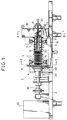
- Fig.1 is a partially sectional view of a screw press of an embodiment of the present invention.
- Fig.2 is a plan view of the screw press shown in Fig. 1.
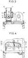
- Fig.3 is a right side view of the screw press of the Fig.1 and shows one portion taken in the line III-III in Fig.2.
- Fig.4 is a left side view of the screw press shown in Fig.1.
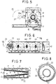
- Fig.5 is a cross-sectional view taken in line V-V shown in Fig.1.
- Fig.6 is a perspective view showing a high pressure cleaning device for cleaning the outer screen casing and the screw shaft of the screw press, and meshes of the outer screen casing.
- Fig.7 is a cross sectional view taken in line VII-VII of Fig.6 showing a double filtering.
- Fig.8 is a cross sectional view showing the screw shaft decentering relative to the outer screen casing.
- Fig.9 is a diaphragm showing various driving units of the screw press of Fig.1.
- a screw press 1 of the embodiment of this invention is mounted on a main support 2.
- a frame 3 is secured to the main support 2.
- Three rollers 4 are disposed on two portions of the frame 3, respectively.
- Two out of three rollers 4 are disposed on the lower portion of the frame 3 and the other roller 4 is disposed on the center of the upper portion of the frame 3.
- An outer screen casing 5 which is mainly made from a metal mesh is reinforced and integrated with a plurality of rings 6.
- the outer screen casing 5 is supported horizontally by the roller 4 through a pair of rings 7 at the both ends of the outer screen casing 5.
- a driven gear 8 is disposed on the outer left end of the outer screen casing 5.
- the right end of the outer screen casing 5 is connected through a flange 9 with a hopper 10 which serves as a slurry supplying part.
- the hopper 10 has a rectangular cylindrical shape and is provided with a mesh basket 11 inside thereof.
- the mesh basket 11 has a lower portion having a semi-cylindrical shape at the position of elongating a lower semi-circle of the outer screen casing 5.
- a chute 13 is placed under the mesh basket 11.
- the slurry added flocculant is supplied to the hopper 10 from the above thereof.
- Solid material produced by flocculating the slurry is supplied into the hopper without being destroyed because there is no pipe for supplying the slurry in the hopper 10.
- the solid material of the slurry is precipitated and the supernatant liquid thereof stays in the upper part of the hopper 10.
- the supernatant liquid is lead through two drains 14 to the chute 13 mounted under the hopper 10, and then drained from a drain dish 15 which is disposed below the hopper 10 and supported by the main support 2.
- the slurry at a bottom of the hopper 10 is filtered through a mesh 12 on the lower portion of the mesh basket 11.
- the filtrate is then drained to the drain dish 15 through the chute 13. Consequently, the solid material is mainly left on the bottom of the hopper 10 and the slurry supplying part serves as a thickener.
- a circular cone 18 is arranged coaxially inside the outer screen casing 5.
- a base end which is a taper portion of the circular cone 18 is positioned at the bottom portion of the hopper 10 and is protruded therefrom.
- the diameter of the circular cone 18 becomes larger toward the opposite end, therefore a space between an outer surface of the circular cone 18 and the outer screen casing 5 becomes gradually narrower.
- Both ends of the circular cone 18 are rotatably supported by bearings 21 which are secured to the frame 3.
- a spiral wing 22 extends all along the length of the outer surface of the circular cone 18 to form a screw shaft 20.
- a motor 25 (Fig.2) is mounted on the main support 2 parallel with the outer screen casing 5.
- a driving shaft 27 of the motor 25 is provided with a transmission 26 comprising a plurality of pinions for engaging with a driven gear 8.
- the pinion 28a (or 28b) of the transmission 26 rotates likewise.
- the pinion 28a or 28b is selected to engage with the driven gear 8 of the outer screen casing 5.
- the outer screen casing 5 rotates counterclockwise.
- Other pinions (not shown) than pinions 28a, 28b can also be selected and thereby the rotational frequency of the outer screen casing 5 can be set variously.
- the driving shaft 27 of the motor 25 further extends through the gear box 26 and is pivoted by a plurality of bearings 28 secured to the main support 2.
- a sprocket wheel 29 is mounted on the top of the driving shaft 27.
- a shaft 30 is arranged parallel to the driving axis 27 of the motor 25 and is supported rotatably by the other bearing 31 secured to the main support 2.
- a sprocket wheel 32 is secured to one end of the shaft 30 and the other end is rigidly secured to the screw shaft 20.
- the sprocket wheel 29 is secured to the driving axis of the motor 25 and the sprocket wheel 32 is secured to the shaft 30.
- a chain 33 is put around the sprocket wheel 29 and the sprocket wheel 32 to transfer the rotation of the motor 25 to the screw shaft 20.
- the screw shaft 20 rotates clockwise, that is, in the opposite rotational direction to the rotational direction of the outer screen casing 5.
- the motor 25 is controlled by a control board 35.
- the circular cone 18 is a hollow circular cone casing.
- the circular cone casing is in the form of a screen as same as the outer screen casing 5.
- a slurry S moves immediately along the spiral wing 22 and is carried to the left side of the spiral wing 22.
- the slurry S then pressed between the outer screen casing 5 and the circular cone 18, and the slurry is filtered by double filters formed by the outer screen casing 5 and the circular cone 18.
- a filtrate F drained outside the outer screen casing 5 is dropped down to the drain groove 15 to be drained.
- the filtrate F drained inside the circular cone 18 is drained through a drain 39.
- the screens of the outer screen casing 5 and the circular cone 18 gradually becomes fine from the hopper 10 toward a drain exit 40 of a cake C. This is because a moisture content of the sludge becomes lower from the hopper toward the drain exit 40 of the cake C.
- An example of the screen of the outer screen casing 5 will be described as follows.
- the size of the mesh of the screen is set for three grades M1, M2 and M3 from the hopper side as shown in Fig.6.
- M1 is a 2mm-mesh screen with a numerical aperture of 40%.
- M2 is a 1mm-mesh screen with a numerical aperture of 22.5%.
- M3 is a 0.5mm-mesh screen with a numerical aperture of 18.6%.
- the size of the mesh of the screen in the circular cone 18 is smaller than that of the outer screen casing 5, it would be possible to have a superior water break to sludge including rich-fiber and to increase quantity of sludge to be treated.
- Cleaning pipes 41 and 42 which inject high pressure water are disposed on the outer portion of the outer screen casing 5 and inside the screw shaft 20, respectively. These cleaning pipes 41 and 42 are connected with a water tank as described below. The high pressure water is force fed to the cleaning pipe 41 and 42 by a pump which is controlled by the control board 35.
- the motor 25 serves as a drive unit which rotates the outer screen casing 5 and the screw shaft 20.
- the motor 25 can be overloaded when the cake as sludge comes to have high content during processing the slurry or the screen is clogged. It is preferred to dispose a detector for detecting the overload as described below. As the overload is detected, it is possible to reduce the load by operating the control board 35 to make the motor 25 rotate backward to rotates the outer screen casing 5 and the screw shaft 20 in the opposite rotational direction to the initial rotational direction, respectively. The above mentioned backward rotation is to be performed for a predetermined period of time.
- Charts 1 and 3 attached to the end of the description indicate the results of the experiments of dehydrate processing the various kinds of slurry by using the screw press of the present invention (the screw press improved to be capable of also inhibiting outer screen casing 5 from being rotated).
- Chart 1 shows a result of the experiment of dehydrate-processing slurry produced by flocculating a paper drainage. This experiment was performed by backwardly rotating the outer screen casing 5 and the screw shaft 20 each other with changing both rotational frequencies N1 and N2 to equalize a difference N1-N2 (the sum of absolute value of their rotational frequency) of both of rotational frequency.
- Chart 3 shows a result of the experiment of dehydrate-processing slurry which is produced by flocculating and depositing a paper drainage. This experiment was to be performed by gradually revving up (backward rotation) the outer screen casing 5 relative to the rotation of the screw shaft 20.
- the Test No.1 was to be performed with the screw shaft 20 having rotational frequency N1 of 0.6rpm.
- the Test No.2 was to be performed with the screw shaft 20 having rotational frequencies N1 of 0.9rpm, the outer screen casing 5 having rotational frequencies N2 of 0, that is, the outer screen casing 5 was fixed to set the difference of rotational frequencies to be also 0.9rpm.
- the dehydrating effect is increased by rotating the outer screen casing 5 in the opposite rotational direction to the rotational direction of the screw shaft 20.
- the rotational ratio N2/N1 of the rotational frequency N2 of the outer screen casing 5 to the rotational frequency N1 of the screw shaft 20 is preferably about 0.1 at the minimum and 0.8 ⁇ 1.2 at the maximum.
- driving force to the slurry is produced by the spiral wing 22 and friction force is produced between the slurry and an inner surface of a slurry chamber defined by the outer screen casing 5 and the screw shaft 20, and the driving force and the friction force multiply act on the slurry during backward rotation of the outer screen casing 5 at a low speed relative to the screw shaft 20 to rapidly move the slurry and to effectively dehydrate the slurry.
- the slurry slips on the inner surface of the slurry chamber to suppress the dehydrating effect and to increase the moisture content.
- Fig.8 is a explanatory drawing of the effect, and shows the condition of the screw shaft 20 decentered relative to the outer screen casing 5.
- Fig.9 shows various drive units each of which drives the above mentioned screw press.
- the screw shaft 20 and the outer screen casing 5 are rotatably driven by the motor 25.
- a first transmission 25 is mounted only on a driving series of the outer screen casing 5 but not on a series of screw shaft 20.
- the diagram of the Fig.9 shows a modified example of screw press having a second transmission 46 for shifting a gear on the driving series of the screw shaft 20 to be able to suitably change the rotational frequency of the screw shaft 20.
- a load detector 48 for detecting the load is disposed on the motor 25.
- the motor 25 suffers from overload and then the screw press does not work sufficiently.
- the load detector 48 detects it to transmit to the control board 35.
- the control board 35 is operated manually or automatically to rotate the motor 25 backwardly for the period of time. Therefore, the screw shaft 20 and the outer screen casing 5 rotate in the opposite rotational directions to the present rotational directions, respectively, to reduce the load of the motor 25.
- the control bad 35 automatically actuates the pump 50 for the above mentioned period of time to feed the water inside the water tank 49 connected with the pump 50 into the cleaning pipes 41 and 42 to high pressure. Accordingly, the high pressured water is injected from the cleaning pipes 41, 42 to clean the inner and outer surfaces of the outer screen casing 5 and the screw shaft 20 and the contact surface thereof. In other wards, the screens of the outer screen casing 5 and the screw shaft, the connecting surfaces of the outer screen casing 5, the screw shaft 20 and the cake are cleaned to further reduce a rotational resistance on the contact surface and then the load of the driving motor 25 is further reduced.
- the present invention should not be limited to the above mentioned embodiments, and should be able to be modified preferably.
- the outer screen casing 5 and the screw shaft 20 are driven by one drive unit 25, it is possible to dispose two drive units and drive the outer screen casing 5 and the screw shaft 20, respectively. It is further possible to dispose the transmission on one or both drive units to separately set the rotational frequency of the outer screen casing 5 and the screw shaft 20, respectively.
- transmissions work by a pulley, sprocket wheel, or other known transmissions may be used.
- the outer screen casing 5 is in shape of a cylinder and the screw shaft 20 is in shape of a circular cone.
- the outer screen casing 5 can be in shape of a circular cone, and the screw shaft 20 can be in shape of a cylinder or in other shapes as long as a relative space between the both narrows in the direction of extending the screw shaft 20.
- the grades may be two, four or more. And it is possible to set the size of the mesh and the numerical aperture smaller in the direction of the screw shaft gradually without any steps.
- the screw press of this invention has an excellent capability of processing dehydration. Moreover, the screw press is capable of resolving an overload to continue the dehydration when it does not work sufficiently by producing the overload. And it is possible to utilize the screw press of this invention in every industries because the screen press of this invention can process every slurry.
- Rotational Frequency Of The Screw Shaft N1 (rpm) Rotational Frequency Of The Outer Screen Casing N2 (rpm) Difference N2-N1 Moisture Content Of Cake (%) Amount Of Processing Dry Cake 1 0.60 -0.30 0.90 56.4 35.6 2 0.90 0 0.90 57.9 33.3 3 0.90 -0.45 1.35 56.6 38.0 4 1.35 0 1.35 60.1 37.3 5 1.20 -0.60 1.80 60.2 54.4 6 1.80 0 1.80 61.8 50.4 CHART 2 TEST No.
Abstract
Description
- This invention relates to a screw press which dehydrates slurry to produce sludge and discharges the sludge.
- A conventional screw press is generally known as following. The screw press has a screw shaft mounted inside an outer screen casing. Slurry is supplied between the screw shaft and the outer screen casing. Slurry is then dehydrated and pressed by rotating the screw shaft to be subjected to a solid-liquid separation, and the produced sludge is discharged as a cake.
- When the cake is formed gradually during the dehydrating operation by the screw press, a load of a drive unit rotating the screw shaft becomes too heavy to press the slurry sufficiently.
- The above mentioned outer screen casing mounted on the screen press is not capable of bearing a large pressure. This is because the outer screen casing is mainly formed from a metal screen. The screw press for dehydrating viscous waste water requires a pressure tightness in order to receives a large pressure. Therefore the metal screen of the outer screen casing mounted on the press is rigidly reinforced by rings, flanges and so on. The screen of the screw press processing the viscous slurry usually has a fine mesh. As a result, the screen tends to clog and then needs to be cleaned. Conventionally, although the clogged screen is cleaned with a brush, it is very difficult to clean the clogged screen to be a good condition because the screen has a very fine mesh and the above mentioned reinforced flange and so forth to prevent the brush from touching to the screen entirely. In case of another method to clean the screen by spraying a compressed air thereto, it is unable to remove the clogging thoroughly.
- It is a primary object of this invention to provide a screw press which improves a capability of dehydration and is capable of reducing a over load on a driving rotation unit rotating a screw shaft during the dehydration, and the screw press having a screen which the clogging of the mesh can be easily cleaned.
- It is another object of this invention to provide a method for driving the screw press in which there are the first step of detecting the over load produced in a drive unit driving the screw press during processing slurry by use of the screw press mentioned above, and the second step of returning to making the screw press perform the slurry process again after reducing the over load, thereby performing the slurry process continuously and efficiently.
- This invention is based on the discovery that the slurry process is effectively performed by rotating an outer screen casing simultaneously with the rotation of the screw shaft at a rotating speed within a predetermined range in the opposite rotational direction of the screw shaft. The screw press of this invention is characterized by a drive unit for rotating the screw shaft in one rotational direction and for rotating the outer screen casing in the opposite rotational direction at the same time. The drive unit has a transmission which changes a rotational frequency of at least either the outer screen casing or the screw shaft.
- An effectiveness of the dehydration by the screw press is acquired especially by setting the rotational frequency of the outer screen casing in the ratio 0.1-1.2 to that of the screw shaft. Therefore, the transmission is characterized by capability of rotating the outer screen casing and the screw shaft by the above ratio.
- The above mentioned screw shaft is characterized by a hollow shaft having an outer surface of screen for filtering the slurry. Therefore, the dehydration efficiency becomes higher by performing a double filtration.
- The above mentioned screw press comprises a device for detecting the overload when it is produced in above mentioned drive unit and a device for rotating at least either the outer screen casing and the screw shaft in a rotational direction opposite to their present rotational direction for a predetermined period of time against said overload. Therefore, the load of the drive unit is reduced.
- In the screw press above described, a high pressure cleaning device is disposed inside the screw shaft and on the portion adjacent to the outer surface of the outer screen casing. Therefore, it is possible to reduce the overload by cleaning the screen and the contact surfaces of the outer screen casing and the screw shaft with the cake by using the device which injects water or wash liquid at high pressure. The cleaning device is also used for cleaning the outer screen casing and the screw shaft after the dehydration.
- In a method of the present invention for driving the screw press, the drive unit rotates at least either the outer screen casing or the screw shaft in a rotational direction opposite to an initial rotational direction for a predetermined period of time. Thereafter, the drive unit returns to the initial driving condition to rotate the outer screen casing and the screw shaft in the initial rotational direction.
- When overload is produced in the drive unit during the above driving method, it is possible to reduce the overload by cleaning the contacting surface of the outer screen casing and the screw shaft with the cake using the high pressure cleaning device.
- Fig.1 is a partially sectional view of a screw press of an embodiment of the present invention.
- Fig.2 is a plan view of the screw press shown in Fig. 1.
- Fig.3 is a right side view of the screw press of the Fig.1 and shows one portion taken in the line III-III in Fig.2.
- Fig.4 is a left side view of the screw press shown in Fig.1.
- Fig.5 is a cross-sectional view taken in line V-V shown in Fig.1.
- Fig.6 is a perspective view showing a high pressure cleaning device for cleaning the outer screen casing and the screw shaft of the screw press, and meshes of the outer screen casing.
- Fig.7 is a cross sectional view taken in line VII-VII of Fig.6 showing a double filtering.
- Fig.8 is a cross sectional view showing the screw shaft decentering relative to the outer screen casing.
- Fig.9 is a diaphragm showing various driving units of the screw press of Fig.1.
- Following is a further explanation of a screw press, a method of driving the screw press, other objects and effects of the present invention with an embodiment.
- Referring to Figs.1 and 5, a
screw press 1 of the embodiment of this invention is mounted on amain support 2. As shown in Fig.1 and Fig.5, aframe 3 is secured to themain support 2. Threerollers 4 are disposed on two portions of theframe 3, respectively. Two out of threerollers 4 are disposed on the lower portion of theframe 3 and theother roller 4 is disposed on the center of the upper portion of theframe 3. Anouter screen casing 5 which is mainly made from a metal mesh is reinforced and integrated with a plurality ofrings 6. Theouter screen casing 5 is supported horizontally by theroller 4 through a pair ofrings 7 at the both ends of theouter screen casing 5. As illustrated in Figs.2 and 5, a drivengear 8 is disposed on the outer left end of theouter screen casing 5. On the other hand, as illustrated in Figs.1 and 3, the right end of theouter screen casing 5 is connected through a flange 9 with ahopper 10 which serves as a slurry supplying part. Thehopper 10 has a rectangular cylindrical shape and is provided with amesh basket 11 inside thereof. Themesh basket 11 has a lower portion having a semi-cylindrical shape at the position of elongating a lower semi-circle of theouter screen casing 5. Achute 13 is placed under themesh basket 11. - The slurry added flocculant is supplied to the
hopper 10 from the above thereof. Solid material produced by flocculating the slurry is supplied into the hopper without being destroyed because there is no pipe for supplying the slurry in thehopper 10. The solid material of the slurry is precipitated and the supernatant liquid thereof stays in the upper part of thehopper 10. The supernatant liquid is lead through twodrains 14 to thechute 13 mounted under thehopper 10, and then drained from adrain dish 15 which is disposed below thehopper 10 and supported by themain support 2. The slurry at a bottom of thehopper 10 is filtered through amesh 12 on the lower portion of themesh basket 11. The filtrate is then drained to thedrain dish 15 through thechute 13. Consequently, the solid material is mainly left on the bottom of thehopper 10 and the slurry supplying part serves as a thickener. - A circular cone 18 is arranged coaxially inside the
outer screen casing 5. A base end which is a taper portion of the circular cone 18 is positioned at the bottom portion of thehopper 10 and is protruded therefrom. The diameter of the circular cone 18 becomes larger toward the opposite end, therefore a space between an outer surface of the circular cone 18 and theouter screen casing 5 becomes gradually narrower. Both ends of the circular cone 18 are rotatably supported bybearings 21 which are secured to theframe 3. Aspiral wing 22 extends all along the length of the outer surface of the circular cone 18 to form ascrew shaft 20. - A motor 25 (Fig.2) is mounted on the
main support 2 parallel with theouter screen casing 5. A drivingshaft 27 of themotor 25 is provided with atransmission 26 comprising a plurality of pinions for engaging with a drivengear 8. When rotating the drivingaxis 27 clockwise by driving the motor in Fig.5, thepinion 28a (or 28b) of thetransmission 26 rotates likewise. Thepinion gear 8 of theouter screen casing 5. As a result, theouter screen casing 5 rotates counterclockwise. Other pinions (not shown) thanpinions outer screen casing 5 can be set variously. - Because the
pinion gear 8, a down force is produced to press theouter screen casing 5 downwardly. The twolower rollers 4 makes theouter screen casing 5 to be stable against the above mentioned force, namely, supports theouter screen casing 5 steadily without decentering thescrew shaft 20. The drivingshaft 27 of themotor 25 further extends through thegear box 26 and is pivoted by a plurality of bearings 28 secured to themain support 2. Asprocket wheel 29 is mounted on the top of the drivingshaft 27. - A
shaft 30 is arranged parallel to the drivingaxis 27 of themotor 25 and is supported rotatably by theother bearing 31 secured to themain support 2. Asprocket wheel 32 is secured to one end of theshaft 30 and the other end is rigidly secured to thescrew shaft 20. Thesprocket wheel 29 is secured to the driving axis of themotor 25 and thesprocket wheel 32 is secured to theshaft 30. Achain 33 is put around thesprocket wheel 29 and thesprocket wheel 32 to transfer the rotation of themotor 25 to thescrew shaft 20. Thescrew shaft 20 rotates clockwise, that is, in the opposite rotational direction to the rotational direction of theouter screen casing 5. Themotor 25 is controlled by acontrol board 35. - As illustrated in detail in Figs.6 and 7, the circular cone 18 is a hollow circular cone casing. The circular cone casing is in the form of a screen as same as the
outer screen casing 5. As thespiral wing 22 extends to the bottom portion of thehopper 10, when thescrew shaft 20 rotates, a slurry S moves immediately along thespiral wing 22 and is carried to the left side of thespiral wing 22. At the same time, the slurry S then pressed between theouter screen casing 5 and the circular cone 18, and the slurry is filtered by double filters formed by theouter screen casing 5 and the circular cone 18. A filtrate F drained outside theouter screen casing 5 is dropped down to thedrain groove 15 to be drained. The filtrate F drained inside the circular cone 18 is drained through adrain 39. - The screens of the
outer screen casing 5 and the circular cone 18 gradually becomes fine from thehopper 10 toward adrain exit 40 of a cake C. This is because a moisture content of the sludge becomes lower from the hopper toward thedrain exit 40 of the cake C. An example of the screen of theouter screen casing 5 will be described as follows. The size of the mesh of the screen is set for three grades M1, M2 and M3 from the hopper side as shown in Fig.6. M1 is a 2mm-mesh screen with a numerical aperture of 40%. M2 is a 1mm-mesh screen with a numerical aperture of 22.5%. M3 is a 0.5mm-mesh screen with a numerical aperture of 18.6%. - Furthermore, if the size of the mesh of the screen in the circular cone 18 is smaller than that of the
outer screen casing 5, it would be possible to have a superior water break to sludge including rich-fiber and to increase quantity of sludge to be treated. - Cleaning
pipes outer screen casing 5 and inside thescrew shaft 20, respectively. These cleaningpipes cleaning pipe control board 35. - The
motor 25 serves as a drive unit which rotates theouter screen casing 5 and thescrew shaft 20. Themotor 25 can be overloaded when the cake as sludge comes to have high content during processing the slurry or the screen is clogged. It is preferred to dispose a detector for detecting the overload as described below. As the overload is detected, it is possible to reduce the load by operating thecontrol board 35 to make themotor 25 rotate backward to rotates theouter screen casing 5 and thescrew shaft 20 in the opposite rotational direction to the initial rotational direction, respectively. The above mentioned backward rotation is to be performed for a predetermined period of time. By injecting high pressure water from the cleaningpipe outer screen casing 5, thescrew shaft 20, all the contacting surface of the cake and the screen and to further reduce the load of thedrive unit 25. - The description will proceed to an effect to oppositely rotate the
outer screen casing 5 to thescrew shaft 20.Charts outer screen casing 5 from being rotated). -
Chart 1 shows a result of the experiment of dehydrate-processing slurry produced by flocculating a paper drainage. This experiment was performed by backwardly rotating theouter screen casing 5 and thescrew shaft 20 each other with changing both rotational frequencies N1 and N2 to equalize a difference N1-N2 (the sum of absolute value of their rotational frequency) of both of rotational frequency. -
Chart 2 shows a result of the experiment of dehydrate-processing sludge produced by a sewerage disposal plant. This experiment was to be performed by one case that theouter screen casing 5 was fixed (theouter screen casing 5 having a rotational frequency N2=0) and thescrew shaft 20 was gradually revved up, and other case that rotational frequency N2 (the backward rotation) of theouter screen casing 5 was gradually revved up relative to thescrew shaft 20. -
Chart 3 shows a result of the experiment of dehydrate-processing slurry which is produced by flocculating and depositing a paper drainage. This experiment was to be performed by gradually revving up (backward rotation) theouter screen casing 5 relative to the rotation of thescrew shaft 20. - According to the
chart 1, the Test No.1 was to be performed with thescrew shaft 20 having rotational frequency N1 of 0.6rpm. Theouter screen casing 5 having rotational frequency N2 of -0.3rpm, so as to have the difference of the rotational frequencies N1-N2 of 0.9rpm. The Test No.2 was to be performed with thescrew shaft 20 having rotational frequencies N1 of 0.9rpm, theouter screen casing 5 having rotational frequencies N2 of 0, that is, theouter screen casing 5 was fixed to set the difference of rotational frequencies to be also 0.9rpm. Although the differences of rotational frequencies are the same 0.9rpm, the Test No.1 by backwardly rotating theouter screen casing 5 resulted in 56.4% of the moisture content and 35.6Kg-DS/hr of processing amount of the dry cake, and had higher processing effect in comparison with the Test No.2 by fixing theouter screen casing 5 being resulted in 57.9% of the moisture content and 33.3Kg-DS/hr of the processing amount of the dry cake. The same results could be acquired in the Test No.3 and No.4, No.5 and No.6. - In the Test shown in Fig.2, when the
outer screen casing 5 was fixed and the rotation of thescrew shaft 20 was revved up, the moisture content and the processing amount became larger (Tests No.7-9). On the other hand, when the rotational frequencies N1 of thescrew shaft 20 was unchanged and the rotational frequency N2 of theouter screen casing 5 was gradually revved up, the moisture content was almost constant but the processing amount was increased a great deal (Tests No.10 and 11, No.12 and 13, No.14-16). However, when the rotational frequency of theouter screen casing 5 more than a certain degree relative to thescrew shaft 20, a increasing rate of the moisture content became larger in comparison with that of the processing amount (Tests No.15 and 16). - In the Test shown in Fig.3, when the rotational frequency (backward rotation) of the
outer screen casing 5 revved up with fixing rotational frequency of thescrew shaft 20, the moisture content was almost unchanged but the processing amount increased (Tests No.19 or 22). However, when the rotational ratio N2/N1 of theouter screen casing 5 to thescrew shaft 20 was increased rather than a certain degree, the moisture content becomes larger (Tests No.18 and 23). - Therefore, it is obvious that the dehydrating effect is increased by rotating the
outer screen casing 5 in the opposite rotational direction to the rotational direction of thescrew shaft 20. Furthermore, the rotational ratio N2/N1 of the rotational frequency N2 of theouter screen casing 5 to the rotational frequency N1 of thescrew shaft 20 is preferably about 0.1 at the minimum and 0.8 ∼ 1.2 at the maximum. It will be understood that driving force to the slurry is produced by thespiral wing 22 and friction force is produced between the slurry and an inner surface of a slurry chamber defined by theouter screen casing 5 and thescrew shaft 20, and the driving force and the friction force multiply act on the slurry during backward rotation of theouter screen casing 5 at a low speed relative to thescrew shaft 20 to rapidly move the slurry and to effectively dehydrate the slurry. It will be also understood, when further revving up the rotation of theouter screen casing 5, the slurry slips on the inner surface of the slurry chamber to suppress the dehydrating effect and to increase the moisture content. - As the other effect by backward rotation of the
outer screen casing 5 against thescrew shaft 20, it is possible to drain the cake having an uniform thickness and moisture content from thedrain exit 40 even if thescrew shaft 20 and theouter screen casing 5 are decentered or the spiral wing is partially abraded. Fig.8 is a explanatory drawing of the effect, and shows the condition of thescrew shaft 20 decentered relative to theouter screen casing 5. As long as theouter screen casing 5 is fixed, it is impossible to unify the cake since decentering points C1 and C2 are always placed on the same positions. However, if theouter screen casing 5 rotates backwardly, it is possible to unify the cake because of changing the positions of the decentering points C1 and C2. - Fig.9 shows various drive units each of which drives the above mentioned screw press. At the screw press of the above mentioned embodiment, the
screw shaft 20 and theouter screen casing 5 are rotatably driven by themotor 25. Afirst transmission 25 is mounted only on a driving series of theouter screen casing 5 but not on a series ofscrew shaft 20. The diagram of the Fig.9 shows a modified example of screw press having asecond transmission 46 for shifting a gear on the driving series of thescrew shaft 20 to be able to suitably change the rotational frequency of thescrew shaft 20. A load detector 48 for detecting the load is disposed on themotor 25. - The description will be made with regard to a method of driving the
screw press 1 with reference to the Figures. - At first, setting the first and second transmissions for rotating the
screw shaft 20 and theouter screen casing 5 at an appropriate rotational ratio. Then themotor 25 was driven to operate thecontrol board 35 to rotates thescrew shaft 20 in one direction and theouter screen casing 5 in the opposite direction. Thescrew shaft 20 is usually rotated at the speed of 1-10rpm. Therefore, the slurry in the slurry supplying part (not shown) is transferred along thespiral wing 22 to be dehydrated and pressed. The formed cake is discharged from thedrain exit 40. Aring 55 having a taper surface is disposed in thedrain exit 40. Thering 55 is connected to apiston rod 54 having two oil pressure cylinders. Theoil pressure cylinder 53 is driven to operate thecontrol board 35 to drive the oilpressure pump unit 52. Therefore, it is possible to set the position of thering 55 by moving thering 55 right or left. It is possible to adjust the amount of draining the cake and the amount of the pressure force pressing the cake by controlling the position of thering 55. - When the pressed cake has a high viscosity or a solidity and when the screens of the
outer screen casing 5 and the screw shaft are clogged, themotor 25 suffers from overload and then the screw press does not work sufficiently. When the load of themotor 25 approaches a predetermined degree, the load detector 48 detects it to transmit to thecontrol board 35. In this time, thecontrol board 35 is operated manually or automatically to rotate themotor 25 backwardly for the period of time. Therefore, thescrew shaft 20 and theouter screen casing 5 rotate in the opposite rotational directions to the present rotational directions, respectively, to reduce the load of themotor 25. When themotor 25 is operated to be rotated backwardly, the control bad 35 automatically actuates thepump 50 for the above mentioned period of time to feed the water inside thewater tank 49 connected with thepump 50 into the cleaningpipes pipes outer screen casing 5 and thescrew shaft 20 and the contact surface thereof. In other wards, the screens of theouter screen casing 5 and the screw shaft, the connecting surfaces of theouter screen casing 5, thescrew shaft 20 and the cake are cleaned to further reduce a rotational resistance on the contact surface and then the load of the drivingmotor 25 is further reduced. - The present invention should not be limited to the above mentioned embodiments, and should be able to be modified preferably. For instance, it is possible to mount the
pinion 28a and the drivengear 8 of theouter screen casing 5 thereon without the transmission for the drive unit, and to set these gear ratio to the predetermined value and a ratio of rotations of thescrew shaft 20 and theouter screen casing 5 to a predetermined value. - Although, in the above embodiment, the
outer screen casing 5 and thescrew shaft 20 are driven by onedrive unit 25, it is possible to dispose two drive units and drive theouter screen casing 5 and thescrew shaft 20, respectively. It is further possible to dispose the transmission on one or both drive units to separately set the rotational frequency of theouter screen casing 5 and thescrew shaft 20, respectively. - It is also possible to dispose one drive unit as indicated in the above embodiment, and to dispose one transmission right next to the drive unit wherein the transmission is capable of changing the rotational frequency of either the
outer screen casing 5 or thescrew shaft 20 or both. - Other than the transmission worked by a gear shift, transmissions work by a pulley, sprocket wheel, or other known transmissions may be used.
- In the above embodiment, the
outer screen casing 5 is in shape of a cylinder and thescrew shaft 20 is in shape of a circular cone. As opposed to the above, theouter screen casing 5 can be in shape of a circular cone, and thescrew shaft 20 can be in shape of a cylinder or in other shapes as long as a relative space between the both narrows in the direction of extending thescrew shaft 20. - In the mentioned embodiment, there are three grades in the size of the mesh of the screen and the numerical aperture, the grades may be two, four or more. And it is possible to set the size of the mesh and the numerical aperture smaller in the direction of the screw shaft gradually without any steps.
- The screw press of this invention, as described above, has an excellent capability of processing dehydration. Moreover, the screw press is capable of resolving an overload to continue the dehydration when it does not work sufficiently by producing the overload. And it is possible to utilize the screw press of this invention in every industries because the screen press of this invention can process every slurry.
CHART 1TEST No. Rotational Frequency Of The Screw Shaft N1 (rpm) Rotational Frequency Of The Outer Screen Casing N2 (rpm) Difference N2-N1 Moisture Content Of Cake (%) Amount Of Processing Dry Cake 1 0.60 -0.30 0.90 56.4 35.6 2 0.90 0 0.90 57.9 33.3 3 0.90 -0.45 1.35 56.6 38.0 4 1.35 0 1.35 60.1 37.3 5 1.20 -0.60 1.80 60.2 54.4 6 1.80 0 1.80 61.8 50.4 CHART 2TEST No. Rotational Frequency Of The Screw Shaft N1 (rpm) Rotational Frequency Of The Outer Screen Casing N2 (rpm) Ratio N2/N1 Moisture Content Of Cake (%) Amount Of Processing Dry Cake 7 0.380 0 0 82.1 4.7 8 0.446 0 0 82.5 5.3 9 0.558 0 0 83.1 7.8 10 0.255 0.101 0.40 82.0 4.5 11 0.255 0.202 0.79 81.0 5.7 12 0.380 0.085 0.22 82.3 5.7 13 0.350 0.174 0.46 81.3 7.4 14 0.446 0.085 0.19 81.8 7.2 15 0.446 0.223 0.50 81.8 9.1 16 0.446 0.347 0.78 83.0 9.4 CHART 3TEST No. Rotational Frequency Of The Screw Shaft N1 (rpm) Rotational Frequency Of The Outer Screen Casing N2 (rpm) Ratio N2/N1 Moisture Content Of Cake (%) Amount Of Processing Dry Cake 17 0.558 0.438 0.78 53.9 27.7 18 0.558 0.893 1.60 60.7 24.8 19 1.010 0 0 51.9 22.6 20 1.010 0.202 0.20 52.4 26.2 21 1.010 0.438 0.43 54.5 28.2 22 1.010 0.695 0.69 55.6 30.2 23 1.010 0.893 0.89 63.1 29.2
Claims (13)
- A screw press (1) comprising:
an outer screen casing (5) being rotatably supported and extending horizontally;
a screw shaft (20) being rotatably disposed coaxially inside said outer screen casing (5), extending horizontally so as to gradually reduce a relative space between said screw shaft (20) and said outer screen casing (5) in the extending direction, and including a spiral wing (22) disposed around its outer surface all over its extending length to be almost contact with said outer screen casing (5);
a slurry supplying means (10, 11, 14) disposed on one end of said outer screen casing (5) to supply a slurry into said space between said outer screen casing (5) and said screw shaft (20); and
at least one rotating means (25) for rotating said screw shaft (20) in one rotational direction and said outer screen casing (5) in the opposite rotational direction. - A screw press claimed in Claim 1, wherein said one rotating means (25) simultaneously rotates said outer screen casing (5) and said screw shaft (20) in opposite directions each other.
- A screw press claimed in Claim 1, wherein said rotating means (25) is to be set at a rotating ratio between 0.1-1.2 of said outer screen casing (5) to said screw shaft (5).
- A screw press claimed in Claim 1, wherein said rotating means (25) includes a transmission (26, 46) for changing the rotational frequency of at least either said outer screen casing (5) or said screw shaft (20), and is capable of setting said rotational ratio between 0.1-1.2. of said outer screen casing (5) to said screw shaft (20).
- A screw press claimed in Claim 1, further comprising a detector (48) for detecting load of said rotating means (25), and a backward rotating unit (25,35) for backwardly rotating at least either of said outer screen casing (5) and said screw shaft (20) which rotate in said directions each other when said load approaches a predetermined degree.
- A screw press claimed in Claim 1, wherein said outer screen casing (5) has mesh screens (M1, M2, M3) having rather a fine mesh on a cake discharging side (40, M3) compared with on a slurry supplying side (10,M1).
- A screw press claimed in Claim 1, wherein said screw shaft 20 has a hollow shape and has an outer surface in form of a screen for discharging a separated supernatant liquid produced by expressing slurry.
- A screw press claimed in Claim 6, wherein said outer surface of said screw shaft (20) has a mesh screen having a rather fine size compared with a mesh screen of said outer screen casing (5) corresponding to said screen mesh of said screw shaft.
- A screw press claimed in Claim 1, further comprising high pressure cleaning devices (41, 42) being disposed outside said outer screen casing (5) and inside said screw shaft (20).
- A screw press claimed in Claim 1, wherein said slurry supplying means (10, 11, 14) includes a hopper (10) of a vertical type, said hopper (10) having a bottom portion to cross with an end of said outer screen casing (5), said screw shaft (20) having an end portion extending to its crossing portion.
- A screw press claimed in Claims 1 or 9, wherein said slurry supplying means (10, 11, 14) includes means (11, 12, 14) for draining a separated supernatant liquid of said slurry supplied to said slurry supplying means to increase a concentration of said slurry.
- In a method of driving a screw press which comprises an outer screen casing (5) being rotatably supported, a screw shaft (20) being rotatably disposed inside said outer screen casing (5), rotating means (25) for rotating said outer screen casing (5) and said screw shaft (20) in opposite directions, respectively, said screw press being for dehydrating and draining slurry by carrying and pressing said slurry along said screw shaft, the improvement wherein said rotating means (25) is operated so as to backwardly rotate for a predetermined time interval at least either of said outer screen casing (5) and said screw shaft (20) for reducing a load when said load approaches a predetermined degree, thereafter said rotating means (25) being returned to normally rotate said outer screen casing (5) and said screw shaft (20).
- A method of driving a screw press claimed in claim 11, wherein said outer screen casing (5) and said screw shaft (20) have an inner and an outer surfaces, said inner and outer surfaces being cleaned for said predetermined time interval to reduce said load when the load of said rotating means approaches said predetermined degree.
Applications Claiming Priority (1)
| Application Number | Priority Date | Filing Date | Title |
|---|---|---|---|
| PCT/JP1991/001268 WO1993005953A1 (en) | 1991-09-24 | 1991-09-24 | Screw press |
Publications (3)
| Publication Number | Publication Date |
|---|---|
| EP0565714A1 true EP0565714A1 (en) | 1993-10-20 |
| EP0565714A4 EP0565714A4 (en) | 1994-02-02 |
| EP0565714B1 EP0565714B1 (en) | 1996-12-11 |
Family
ID=14014609
Family Applications (1)
| Application Number | Title | Priority Date | Filing Date |
|---|---|---|---|
| EP91916607A Expired - Lifetime EP0565714B1 (en) | 1991-09-24 | 1991-09-24 | Screw press |
Country Status (8)
| Country | Link |
|---|---|
| US (1) | US5357855A (en) |
| EP (1) | EP0565714B1 (en) |
| KR (1) | KR970010548B1 (en) |
| AU (1) | AU654681B2 (en) |
| CA (1) | CA2096125C (en) |
| DE (1) | DE69123601T2 (en) |
| RU (1) | RU2098281C1 (en) |
| WO (1) | WO1993005953A1 (en) |
Cited By (11)
| Publication number | Priority date | Publication date | Assignee | Title |
|---|---|---|---|---|
| EP0685325A2 (en) * | 1994-05-04 | 1995-12-06 | SCHLEGEL, Dietrich, Dr. Ing. | Device for separating the liquid portion from the solid portion in two-phase systems |
| FR2727323A1 (en) * | 1994-11-24 | 1996-05-31 | Kim Young Tae | MULTIPLE SCREW PRESS FOR SPINNING OF RESIDUAL MATERIALS |
| EP0736370A2 (en) * | 1995-04-08 | 1996-10-09 | FILTERWERK MANN & HUMMEL GMBH | Apparatus for dewatering materials |
| WO2000073049A1 (en) * | 1999-05-31 | 2000-12-07 | Spirac Engineering Ab | Apparatus for separation |
| WO2001039965A1 (en) * | 1999-11-30 | 2001-06-07 | Ishigaki Company Limited | Screw press apparatus |
| WO2007057293A1 (en) * | 2005-11-15 | 2007-05-24 | C.M.S. S.P.A. | Apparatus for automatically regulating the action of the constriction means arranged on the discharge mouth of screw presses |
| EP1873123A1 (en) * | 2005-04-14 | 2008-01-02 | Ishigaki Company Limited | Sludge concentration device and sludge concentration method |
| WO2012126584A1 (en) * | 2011-03-18 | 2012-09-27 | Röhren- Und Pumpenwerk Bauer Ges. M. B. H. | Press screw separator |
| JP2015199044A (en) * | 2014-04-10 | 2015-11-12 | 静岡メンテ株式会社 | Screw press type dehydrator |
| CN112373097A (en) * | 2020-10-26 | 2021-02-19 | 赵经丽 | Kitchen waste sewage treatment equipment and treatment method thereof |
| EP4046788A1 (en) * | 2021-02-19 | 2022-08-24 | Babbini S.P.A. | Pressing apparatus |
Families Citing this family (29)
| Publication number | Priority date | Publication date | Assignee | Title |
|---|---|---|---|---|
| US5489383A (en) * | 1993-06-16 | 1996-02-06 | Hitachi Zosen Corporation | Screw type dewatering machine |
| US6279471B1 (en) * | 1995-09-15 | 2001-08-28 | Jeffrey Reddoch | Drilling fluid recovery defluidization system |
| US5996484A (en) * | 1995-09-15 | 1999-12-07 | Reddoch; Jeffrey | Drilling fluid recovery defluidization system |
| ITCR20010001A1 (en) * | 2001-02-08 | 2002-08-08 | B I Mec S R L | FILTER FILTER SCREW WITHOUT END, SEPARATOR OF SOLIDS SUSPENDED IN A LIQUAME, SELF-CLEANING WITH IMPROVED YIELD. |
| DK200100557A (en) * | 2001-04-04 | 2002-10-05 | Atlas Stord Denmark As | Screw press and method of carrying it out |
| WO2003086740A1 (en) * | 2002-04-10 | 2003-10-23 | J.S. Maskinfabrik A/S | A press for pressing liquid out of a medium |
| EP1918008B1 (en) * | 2005-06-16 | 2013-05-01 | Tsukishima Kikai Co., Ltd. | Filtering apparatus and filtering method |
| JP5051889B2 (en) * | 2007-09-26 | 2012-10-17 | 月島機械株式会社 | Filtration apparatus and filtration method |
| US8377301B2 (en) * | 2008-12-15 | 2013-02-19 | 4 M Welding, Inc. | Method and apparatus for treating drilling fluid |
| KR101352947B1 (en) * | 2011-07-22 | 2014-01-22 | 박정오 | a dehydrator for recycled product |
| US9751787B1 (en) * | 2011-08-23 | 2017-09-05 | Daritech, Inc. | Anaerobic digesting systems and methods for processing animal waste |
| HUE038801T2 (en) * | 2013-01-09 | 2018-11-28 | Roehren Und Pumpenwerk Bauer Gmbh | Worm press separator and method for operating the worm press separator |
| US10065136B2 (en) * | 2013-10-25 | 2018-09-04 | Lyco Manufacturing, Inc. | Rotary drum with screen for processing food |
| JP6557254B2 (en) * | 2014-04-08 | 2019-08-07 | プライム ソリューション インク. | Rotating fan press machine with auger |
| CN104139548B (en) * | 2014-07-10 | 2016-02-17 | 郭奋生 | A kind of linseed oil squeezer and utilize this squeezer to carry out the method for expressed oil |
| KR101638476B1 (en) * | 2015-02-12 | 2016-07-13 | 김승평 | Night-soil Fuel Equipment |
| KR102035483B1 (en) * | 2016-03-18 | 2019-11-08 | 한국토지주택공사 | The processing method of food garbage and apparatus thereof |
| US10611700B2 (en) | 2016-04-05 | 2020-04-07 | Dari-Tech, Inc. | Self-flushing anaerobic digester system |
| WO2017211363A1 (en) * | 2016-06-07 | 2017-12-14 | Gea Process Engineering A/S | Screw press apparatus including an improved cip arrangement and method of cleaning the apparatus |
| US10555547B2 (en) * | 2017-02-16 | 2020-02-11 | Wenger Manufacturing Inc. | Meat dewatering assembly |
| CN107175841B (en) * | 2017-06-29 | 2023-07-28 | 云南农业大学 | Spiral jatropha curcas crude oil squeezer |
| US11305233B2 (en) * | 2018-06-04 | 2022-04-19 | CleanWorld | System, device and method for production of high-nitrogen organic liquid fertilizer from ammonia rich wastewaters and digester effluents |
| WO2020068008A1 (en) * | 2018-09-25 | 2020-04-02 | Erol Aslan | A dewatering machine for paper pulp wastes and a method of recycling paper pulp wastes |
| US10486383B1 (en) * | 2018-12-18 | 2019-11-26 | V.Y.F. Express Inc. | Screw press having screen vibration |
| CN109433578A (en) * | 2018-12-26 | 2019-03-08 | 宁波开诚生态技术有限公司 | A kind of draining slag remover |
| BR102019026860A2 (en) | 2019-12-16 | 2021-06-22 | José Oswaldo Da Silva | EQUIPMENT AND METHOD FOR DEWATERING AND COMPACTING SLUDGE, TAILINGS, PASTURE MATERIALS AND SUSPENSIONS |
| DE102021128200A1 (en) * | 2021-10-28 | 2023-05-04 | Vogelsang Gmbh & Co. Kg | Separator device for dewatering a moist mass |
| CN114949978A (en) * | 2022-05-12 | 2022-08-30 | 河南盛邦环境工程有限公司 | Solid-liquid separator for industrial wastewater treatment |
| US20240083130A1 (en) * | 2022-09-09 | 2024-03-14 | John Christopher Mitchell | Dewatering system and method |
Citations (3)
| Publication number | Priority date | Publication date | Assignee | Title |
|---|---|---|---|---|
| DE2923646A1 (en) * | 1978-06-14 | 1979-12-20 | Berggren Torsten L | SCREW PRESS |
| JPS5719197A (en) * | 1980-07-09 | 1982-02-01 | Shokuhin Sangyo Center | Juicing machine |
| WO1988006090A1 (en) * | 1987-02-18 | 1988-08-25 | Hedemora Ab | Method and apparatus for dewatering and squeezing material |
Family Cites Families (13)
| Publication number | Priority date | Publication date | Assignee | Title |
|---|---|---|---|---|
| US1876064A (en) * | 1926-05-08 | 1932-09-06 | American Voith Contact Co Inc | Apparatus for dewatering and washing pulp |
| US2419545A (en) * | 1940-06-19 | 1947-04-29 | Barron Gray Packing Company | Method of and apparatus for extracting juice |
| US2709957A (en) * | 1953-01-16 | 1955-06-07 | Jackson & Church Company | Screen and frame structure with frame functioning as a torque tube |
| FR1484777A (en) * | 1966-05-04 | 1967-06-16 | Choquenet Fond Atel | Rotary Drum Screw Press |
| JPS5412774A (en) * | 1977-06-29 | 1979-01-30 | Lion Fat Oil Co Ltd | Flow rate controlling device for granular solids weighing equipment |
| JPS5412774Y2 (en) * | 1978-03-30 | 1979-06-02 | ||
| SU856853A1 (en) * | 1979-12-17 | 1981-08-28 | Предприятие П/Я Р-6956 | Method of controlling polymeric materials drying process in worm machine |
| JPS619999A (en) * | 1984-06-27 | 1986-01-17 | Jgc Corp | Method for controlling volume reducing device for solid waste |
| US4661290A (en) * | 1984-03-15 | 1987-04-28 | Jgc Corporation | Apparatus for compacting solid waste materials and its accessory facilities |
| JPS60247498A (en) * | 1984-05-21 | 1985-12-07 | Nikko Sogyo Kk | Device for dehydration treatment of sludge and other |
| SU1369917A1 (en) * | 1986-04-18 | 1988-01-30 | Предприятие П/Я Р-6956 | Method of controlling the process of mechanothermal dehydration on wet rubber in worm machines |
| US4844799A (en) * | 1986-07-17 | 1989-07-04 | Lee Chung Y | Filtration apparatus having spaced-apart driving members for changing a size of a treatment zone |
| JPH0357596A (en) * | 1989-07-27 | 1991-03-12 | Ishigaki Kiko Kk | Jam-up preventing device in screw type dehydrator |
-
1991
- 1991-09-24 KR KR1019930701404A patent/KR970010548B1/en not_active IP Right Cessation
- 1991-09-24 WO PCT/JP1991/001268 patent/WO1993005953A1/en active IP Right Grant
- 1991-09-24 EP EP91916607A patent/EP0565714B1/en not_active Expired - Lifetime
- 1991-09-24 CA CA002096125A patent/CA2096125C/en not_active Expired - Lifetime
- 1991-09-24 AU AU86352/91A patent/AU654681B2/en not_active Ceased
- 1991-09-24 RU RU9393043665A patent/RU2098281C1/en not_active IP Right Cessation
- 1991-09-24 US US08/050,449 patent/US5357855A/en not_active Expired - Lifetime
- 1991-09-24 DE DE69123601T patent/DE69123601T2/en not_active Expired - Lifetime
Patent Citations (3)
| Publication number | Priority date | Publication date | Assignee | Title |
|---|---|---|---|---|
| DE2923646A1 (en) * | 1978-06-14 | 1979-12-20 | Berggren Torsten L | SCREW PRESS |
| JPS5719197A (en) * | 1980-07-09 | 1982-02-01 | Shokuhin Sangyo Center | Juicing machine |
| WO1988006090A1 (en) * | 1987-02-18 | 1988-08-25 | Hedemora Ab | Method and apparatus for dewatering and squeezing material |
Non-Patent Citations (2)
| Title |
|---|
| PATENT ABSTRACTS OF JAPAN vol. 6, no. 80 (M-129)19 May 1982 & JP-A-57 019 197 (SHOKUHIN SANGYO) * |
| See also references of WO9305953A1 * |
Cited By (17)
| Publication number | Priority date | Publication date | Assignee | Title |
|---|---|---|---|---|
| EP0685325A2 (en) * | 1994-05-04 | 1995-12-06 | SCHLEGEL, Dietrich, Dr. Ing. | Device for separating the liquid portion from the solid portion in two-phase systems |
| EP0685325A3 (en) * | 1994-05-04 | 1996-01-24 | Dietrich Dr Ing Schlegel | Device for separating the liquid portion from the solid portion in two-phase systems. |
| FR2727323A1 (en) * | 1994-11-24 | 1996-05-31 | Kim Young Tae | MULTIPLE SCREW PRESS FOR SPINNING OF RESIDUAL MATERIALS |
| EP0736370A2 (en) * | 1995-04-08 | 1996-10-09 | FILTERWERK MANN & HUMMEL GMBH | Apparatus for dewatering materials |
| EP0736370A3 (en) * | 1995-04-08 | 1997-02-26 | Mann & Hummel Filter | Apparatus for dewatering materials |
| US5732618A (en) * | 1995-04-08 | 1998-03-31 | Filterwerk Mann & Hummel Gmbh | Apparatus for separating liquid from a material |
| WO2000073049A1 (en) * | 1999-05-31 | 2000-12-07 | Spirac Engineering Ab | Apparatus for separation |
| AU759648B2 (en) * | 1999-11-30 | 2003-04-17 | Ishigaki Company Limited | Screw press apparatus |
| WO2001039965A1 (en) * | 1999-11-30 | 2001-06-07 | Ishigaki Company Limited | Screw press apparatus |
| US6615710B1 (en) | 1999-11-30 | 2003-09-09 | Ishigaki Company Limited | Screw press apparatus |
| EP1873123A1 (en) * | 2005-04-14 | 2008-01-02 | Ishigaki Company Limited | Sludge concentration device and sludge concentration method |
| EP1873123A4 (en) * | 2005-04-14 | 2012-03-14 | Ishigaki Mech Ind | Sludge concentration device and sludge concentration method |
| WO2007057293A1 (en) * | 2005-11-15 | 2007-05-24 | C.M.S. S.P.A. | Apparatus for automatically regulating the action of the constriction means arranged on the discharge mouth of screw presses |
| WO2012126584A1 (en) * | 2011-03-18 | 2012-09-27 | Röhren- Und Pumpenwerk Bauer Ges. M. B. H. | Press screw separator |
| JP2015199044A (en) * | 2014-04-10 | 2015-11-12 | 静岡メンテ株式会社 | Screw press type dehydrator |
| CN112373097A (en) * | 2020-10-26 | 2021-02-19 | 赵经丽 | Kitchen waste sewage treatment equipment and treatment method thereof |
| EP4046788A1 (en) * | 2021-02-19 | 2022-08-24 | Babbini S.P.A. | Pressing apparatus |
Also Published As
| Publication number | Publication date |
|---|---|
| KR970010548B1 (en) | 1997-06-28 |
| EP0565714A4 (en) | 1994-02-02 |
| EP0565714B1 (en) | 1996-12-11 |
| CA2096125C (en) | 1999-02-23 |
| KR930702146A (en) | 1993-09-08 |
| US5357855A (en) | 1994-10-25 |
| RU2098281C1 (en) | 1997-12-10 |
| WO1993005953A1 (en) | 1993-04-01 |
| CA2096125A1 (en) | 1993-03-25 |
| DE69123601D1 (en) | 1997-01-23 |
| AU8635291A (en) | 1993-04-27 |
| AU654681B2 (en) | 1994-11-17 |
| DE69123601T2 (en) | 1997-07-03 |
Similar Documents
| Publication | Publication Date | Title |
|---|---|---|
| EP0565714B1 (en) | Screw press | |
| KR0138261B1 (en) | Device for continuous and automatic draining sludge, especially sewage sludge | |
| US3695173A (en) | Sludge dewatering | |
| CA1063740A (en) | Process for dewatering sludge-type material and an installation for carrying out the process | |
| US6739458B2 (en) | Device for dehydrating sludge | |
| US3275150A (en) | Internally fed drum filter | |
| CN209020270U (en) | A kind of storage and stirring integrated formula sludge treatment pond | |
| KR101437908B1 (en) | Vertical type screw dehydrator | |
| EP1335785B1 (en) | Filtration apparatus | |
| JP2507845B2 (en) | Screw press | |
| KR100224632B1 (en) | Apparatus for filtering waste water | |
| JP5048726B2 (en) | Sediment separation dehydrator | |
| CN115055482A (en) | Automatic comprehensive separation and reuse system for municipal sewage and control method | |
| CN108325258A (en) | Multifunctional solid-liquid seperator and its back-flushing method | |
| EP0288105A2 (en) | Machine for continuously separating solid and semisolid parts from liquid, in the purification of civil and industrial effluents | |
| KR20040100721A (en) | Cylindrical filter press-dehydration machine | |
| US20190375178A1 (en) | Device for continuously pressing liquid out of a suspension | |
| CN110066087B (en) | Automatic unloading and clear mud filter pressing device | |
| CN209778620U (en) | Sludge dewatering equipment for riverbed | |
| CN218478660U (en) | Sludge dewatering treatment device is administered in river course | |
| RU2026710C1 (en) | Plant for preliminary purification of sewage by filtration | |
| CN212982529U (en) | Municipal administration is mud filter equipment for sewage | |
| SU1117314A2 (en) | Device for extracting brewing wort from fruit and berry raw material | |
| JP3142466B2 (en) | Screw dehydrator | |
| SU874645A1 (en) | Device for extracting oils and oil products from waste water |
Legal Events
| Date | Code | Title | Description |
|---|---|---|---|
| PUAI | Public reference made under article 153(3) epc to a published international application that has entered the european phase |
Free format text: ORIGINAL CODE: 0009012 |
|
| AK | Designated contracting states |
Kind code of ref document: A1 Designated state(s): DE FR GB |
|
| 17P | Request for examination filed |
Effective date: 19930908 |
|
| A4 | Supplementary search report drawn up and despatched |
Effective date: 19931216 |
|
| AK | Designated contracting states |
Kind code of ref document: A4 Designated state(s): DE FR GB |
|
| 17Q | First examination report despatched |
Effective date: 19950622 |
|
| GRAH | Despatch of communication of intention to grant a patent |
Free format text: ORIGINAL CODE: EPIDOS IGRA |
|
| GRAH | Despatch of communication of intention to grant a patent |
Free format text: ORIGINAL CODE: EPIDOS IGRA |
|
| GRAA | (expected) grant |
Free format text: ORIGINAL CODE: 0009210 |
|
| AK | Designated contracting states |
Kind code of ref document: B1 Designated state(s): DE FR GB |
|
| REF | Corresponds to: |
Ref document number: 69123601 Country of ref document: DE Date of ref document: 19970123 |
|
| ET | Fr: translation filed | ||
| PLBE | No opposition filed within time limit |
Free format text: ORIGINAL CODE: 0009261 |
|
| STAA | Information on the status of an ep patent application or granted ep patent |
Free format text: STATUS: NO OPPOSITION FILED WITHIN TIME LIMIT |
|
| 26N | No opposition filed | ||
| REG | Reference to a national code |
Ref country code: GB Ref legal event code: IF02 |
|
| PGFP | Annual fee paid to national office [announced via postgrant information from national office to epo] |
Ref country code: GB Payment date: 20090922 Year of fee payment: 19 |
|
| PGFP | Annual fee paid to national office [announced via postgrant information from national office to epo] |
Ref country code: DE Payment date: 20090922 Year of fee payment: 19 |
|
| GBPC | Gb: european patent ceased through non-payment of renewal fee |
Effective date: 20100924 |
|
| REG | Reference to a national code |
Ref country code: FR Ref legal event code: ST Effective date: 20110531 |
|
| REG | Reference to a national code |
Ref country code: DE Ref legal event code: R119 Ref document number: 69123601 Country of ref document: DE Effective date: 20110401 |
|
| PG25 | Lapsed in a contracting state [announced via postgrant information from national office to epo] |
Ref country code: FR Free format text: LAPSE BECAUSE OF NON-PAYMENT OF DUE FEES Effective date: 20100930 Ref country code: DE Free format text: LAPSE BECAUSE OF NON-PAYMENT OF DUE FEES Effective date: 20110401 |
|
| PG25 | Lapsed in a contracting state [announced via postgrant information from national office to epo] |
Ref country code: GB Free format text: LAPSE BECAUSE OF NON-PAYMENT OF DUE FEES Effective date: 20100924 |
|
| PGFP | Annual fee paid to national office [announced via postgrant information from national office to epo] |
Ref country code: FR Payment date: 20091001 Year of fee payment: 19 |