EP0565505A2 - Duplex power control in a cellular mobile radio telephone system - Google Patents
Duplex power control in a cellular mobile radio telephone system Download PDFInfo
- Publication number
- EP0565505A2 EP0565505A2 EP93850067A EP93850067A EP0565505A2 EP 0565505 A2 EP0565505 A2 EP 0565505A2 EP 93850067 A EP93850067 A EP 93850067A EP 93850067 A EP93850067 A EP 93850067A EP 0565505 A2 EP0565505 A2 EP 0565505A2
- Authority
- EP
- European Patent Office
- Prior art keywords
- mobile
- base station
- signal
- power
- signal strength
- Prior art date
- Legal status (The legal status is an assumption and is not a legal conclusion. Google has not performed a legal analysis and makes no representation as to the accuracy of the status listed.)
- Granted
Links
Images


Classifications
-
- H—ELECTRICITY
- H04—ELECTRIC COMMUNICATION TECHNIQUE
- H04B—TRANSMISSION
- H04B7/00—Radio transmission systems, i.e. using radiation field
- H04B7/24—Radio transmission systems, i.e. using radiation field for communication between two or more posts
- H04B7/26—Radio transmission systems, i.e. using radiation field for communication between two or more posts at least one of which is mobile
-
- H—ELECTRICITY
- H04—ELECTRIC COMMUNICATION TECHNIQUE
- H04W—WIRELESS COMMUNICATION NETWORKS
- H04W52/00—Power management, e.g. TPC [Transmission Power Control], power saving or power classes
- H04W52/04—TPC
- H04W52/30—TPC using constraints in the total amount of available transmission power
- H04W52/34—TPC management, i.e. sharing limited amount of power among users or channels or data types, e.g. cell loading
- H04W52/346—TPC management, i.e. sharing limited amount of power among users or channels or data types, e.g. cell loading distributing total power among users or channels
-
- H—ELECTRICITY
- H04—ELECTRIC COMMUNICATION TECHNIQUE
- H04W—WIRELESS COMMUNICATION NETWORKS
- H04W52/00—Power management, e.g. TPC [Transmission Power Control], power saving or power classes
- H04W52/04—TPC
- H04W52/38—TPC being performed in particular situations
- H04W52/44—TPC being performed in particular situations in connection with interruption of transmission
Definitions
- the invention described here relates to radio communications systems, and in particular, to duplex power control systems for cellular radio telephone systems.
- a cellular radio telephone system divides a geographical area up into cells where neighboring cells are generally allocated different operating frequencies so as to avoid interference. Because of the relatively low power communication transmissions with a particular cell, another cell spaced two or more cells away may typically re-use the same frequencies. The further apart cells re-using similar frequencies are located, the lower the interference level between them.
- the frequency re-use/cell pattern is important in determining the desired signal-to-interference ratio (C/I) in a cell.
- CDMA Code Division Multiple Access
- DTX Discontinuous Transmission
- TDMA Time Division Multiple Access
- GSM Pan-European Digital Cellular System
- Another technique for reducing interference between signals in neighboring cells on the same frequency is to configure the transmission power distribution of a cell over all of the mobiles within a cell according to each mobile's distance from its respective cell edge.
- the power transmitted downlink from a base station in the center of the cell to a mobile on the cell edge should be the greatest.
- the power level should follow a fourth power radius law based on the distance or radius of the mobile from the cell center where typically the base station is located.
- the mobile's transmission power should also be set according to a fourth power radius law, in order to equalize the signal strengths received at the base station and to prevent those mobiles closest to the base station from using unnecessary power levels that would cause substantial interference.
- a single control loop regulates the power transmitted by the base station to its associated mobiles and the power transmitted by those mobiles to the base station.
- the base station monitors each mobile transmitter's power by measuring the signal strength of signals received from each mobile. If a mobile's power level has increased or decreased, the base station adjusts that fraction of its total transmitter power that is apportioned to transmissions to that mobile to compensate for the power level change. In turn, the mobile detects that adjusted power level and increases (or decreases) its transmission power in accordance with the detected power.
- Each mobile measures the signal strength of that portion of the total base station signal specifically intended for that mobile, and compares that signal strength value to either the total base station signal power or in a relative manner to a cumulative ranking of base station signal strengths intended for other mobiles. From that comparison, the mobile increases or decreases its transmission power.
- Each mobile's comparison of relative signal strength of received signals from the base station to the signal strength comparison of signals received by other mobiles from the same base station eliminates the affect of multi-path fading on the base-mobile signal path because all of the signals fade more or less equally. As a result, fading in the downlink direction from base station to mobile does not cause undue variations in how the mobile determines its transmitter power.
- the present invention essentially accomplishes duplex power regulation for both uplink and downlink communications simultaneously using only one control loop.
- This control loop is more efficient than the prior art techniques requiring exchange of powercon- trol data messages between the mobiles and base station, and it also compensates for multipath fading affects not accounted for in the prior art systems.
- the invention applies to radio communications systems between base stations and a multiplicity of mobiles where the power levels transmitted by each mobile and by the base station may be controlled to provide optimal signal power levels in order to reduce interference in surrounding cells.
- the present invention is described in the context of discrete and continuous transmissions from mobile to base and base to mobile.
- a base station 100 is equipped with transmitters (16a, 16b, 16c%) for transmitting different data signals to a plurality of mobile stations via a transmitter amplifier 17 and an antenna 18.
- the relative power level of each transmitted signal is determined by a power control unit 14.
- the power control unit 14 determines and sets the power levels for signal transmissions apportioned to each mobile based on the relative power levels measured by the receivers 11, 12a, 12b, 12c... of the signals received from each respective mobile station via an antenna 10.
- the sum of all of the signals transmitted by the base station 100 combine to define a composite signal.
- a mobile station 200 is equipped with a receiver 22 which operates in a conventional manner to filter, amplify and demodulate a signal from antenna 20.
- Afirst decoder 24 is provided for selectively receiving and decoding its intended signal transmitted from the base station 100 and measuring its signal strength. Data signals demodulated in the first decoder 24 are generated as output data signals for subsequent use. Other signals transmitted from the base station 100 intended for other mobiles within its cell are received and decoded in a second decoder 26 where their respective signal strengths are measured.
- a signal strength calculator 28 receives the signal strength measurements from both of the first and second decoders 24 and 26 and calculates a transmission power for the mobile 200 to use in transmissions to the base station 100.
- the data input signals to be transmitted from the mobile 200 to the base station 100 are received in a modulator 34.
- a transmitter 32 receives the modulated signal.
- a power level controller 30 Based on the transmission power calculated by the signal strength calculator 28, a power level controller 30 varies the power of the transmitter 32 to transmit a mobile output signal.
- the base station 100 power control unit 14 of the base station 100 determines that a particular mobile's signal strength is greater (or weaker) than signal strengths received from the other mobiles, the base station 100 power control unit 14 reduces the power of a corresponding transmitter, e.g., transmitter 16a. That power reduction is implemented not as an instantaneous change but rather as a gradual change from the present power value towards the new target value over a period of time, e.g., 20 msec.
- the signal strength calculator 28 determines that the strength of the signal from the base station 100 to the mobile 200 has been reduced relative to the signal strength previously received.
- the actual power reduction is determined either by computing the ratio of the signal strength value received by the mobile decoder 24 to the mean of the total signal power transmitted to all of the mobiles in the cell, or by determining the position of the signal received by the mobile 200 in a relative signal strength ranking with signals for other mobiles within the cell.
- the mobile power level controller 30 changes the target power level for the mobile transmitter 32 from a power value P5 to a lower power target value P6.
- These power values P1, P2, P3 Vietnamese may be stored in a memory in a predetermined table format.
- the power level controller 30 then decreases the actual value of the transmitted mobile power over a predetermined time period from P5 towards P6. If at the end of that time period, the transmitted mobile power has only reached some intermediate value Pi and new signal strength measurements result in a new target value Pn, then the power level is gradually changed from the current value Pi towards the target value Pn.
- non-linear function P(r) depends on the particular communications scenario such as the number of mobile stations supported by each cell, the type of modulation, the frequency re-use pattern, the distribution of mobiles in the cell, the physical geography within the cell, the desired C/I ratio, etc., and may be specified by a predetermined look-up table.
- control loop essentially includes the base station detecting power level changes from individual mobiles in its cell as those mobiles move further or closer, behind buildings, etc., and adjusting the power level of the base station transmitter associated with each mobile to minimize the affect of those power level changes.
- a mobile detects that change in base station transmission power level allocated to that mobile, it modifies its transmission power level to match the detected change. No bidirectional messages or signalling between the base station and mobiles is required.
- a preferred embodiment of the present invention for a duplex power control system is described for purposes of illustration in the context of a subtractive CDMA cellular telephone system similar to that disclosed in U.S. Patent Application Serial No. 07/628,359, filed on December 17,1990, assigned to the present assignee.
- the subject matter of this application is expressly incorporated by reference.
- a mobile station 200 for implementing this preferred embodiment is illustrated in Figure 3.
- a duplexer 52 allows both a receiving amplifier 54 and a transmitter 70 to be connected to an antenna 50 simultaneously.
- the amplifier 54 amplifies a received, composite signal which includes signals from the base station to all of the mobile stations within its cell as well as interference.
- a filter 56 filters the amplifier output signal to remove extraneous noise.
- the filter 56 output signal consisting of a coded block of superimposed CDMA signals from the corresponding base station 100, is divided into its real and imaginary (quadrature or I,Q) components and digitized in a dual-channel A-to-D convertor 58.
- a CDMA signal processor 60 and a signal strength tracker and sorter 62 form a CDMA demodulator 63.
- the CDMA processor 60 demodulates the strongest signal from the composite signal and subtracts the demodulated signal from the composite received signal in an iterative demodulation process until all of the coded, mobile signals from the base station 100 are demodulated.
- the signal strength values of each demodulated signal code block are sorted in the signal strength tracker and sorter 62 in the order of strongest to weakest signal strength value and used to predict the relative strengths of the signals for the next code block.
- Adetailed description of the subtractive CDMA demodulation procedure is provided in the above-described patent application which has been incorporated by reference.
- the position in signal strength order of that portion of the base station signal intended for a particular mobile is assigned a relative power level value by the signal strength tracker and sorter 62 and stored in a memory look-up table 64.
- the signal strength tracker and sorter 62 assigns power levels according to the relative signal strength order. A higher relative signal strength would correspond, for example, to a greater power level value and vice versa.
- Each power level in the relative power level order is associated with a particular mobile and each mobile's power level is sent to its respective power controller 66. If the power level associated with that particular mobile has changed since the last iteration, the power controller 66 regulates that mobile transmitter's 70 output power towards the new power level value.
- the power controller 66 imposes a time constant on the change from the present power to the newly determined power level sothatthe base station 100 does not experience sudden step changes in the received power level from that mobile. For example, the power controller 66 might ramp the power level from the present value to the desired value at a limited rate so that it does not change more than 0.10 decibels between successive code blocks. If a code block has a typical duration of 0.50 msec, the rate of power change may be 200dB per second. This rate is sufficiently high to partially minimize the effects of signal fading.
- the ratio "r" of the power of that portion of the base station signal So intended for one mobile divided by the total power of all the mobile signals within the cell Sm is used as a continuous power control variable.
- This continuous variable is transformed through the non-linear function P(r) to obtain the new, desired value of the mobile transmitter power.
- the non-linearfunction P(r) may be implemented by numerically approximating the continuous variable "r" to a certain number of bits, e.g., 8 bits, and using it to address a look-up table, e.g., having 256 locations.
- the look-up table representing P(r) is predetermined so that for each of 256 "r" values, a corresponding value P(r) is addressed and retrieved. Greater precision is achieved by increasing the number of bits representing the ratio "r”, e.g., 10 bits generates 1024 values stored in the lookup table. Of course, if "r" was truly continuous, a lookup table would be infinitely large.
- the ratio "r" may be expressed either as a power ratio, a voltage ratio, or in dB's, i.e., on a logarithmic scale.
- a simulation of a non-linear function P(r) for achieving an optimum relationship between uplinkand downlink relative power is illustrated graphically in Fig. 5.
- the cell is assumed to contain 24 active mobiles numbered 1-24 along the horizontal axis in increasing distance from the base station.
- the graph in Fig. 5 illustrates the non-linear correspondence between distribution of base station power to mobiles on the downlink and mobile transmitter power required uplink to the base station.
- the curve labelled Power Share shows for the particular system simulated the proportion of the total base station transmitter power each mobile should receive (in dB below total transmitted base station power) to achieve equality in signal quality at each mobile. Consequently, mobile 1 receives -42dB of the total power while mobile 24 receives -8dB, a difference of 34dB.
- mobile 24 is 24 further times away than mobile 1, assuming a uniform area distribution of mobiles, and based on the fourth power radius law referenced above, the mobile 24 needs to transmit (24) 2 times as much power as mobile 1 which is equivalent to 28dB.
- mobile 10 gets 22dB more base station power than mobile 1 but should transmit 20dB more back to the base station, etc.
- each mobile adjusts its transmitter power in response to changes of signal strength intended forthat mobile received from the base station according to the non-linear function P(r).
- Another objective of the present invention in adjusting mobile transmitter power is to achieve equal signal-to-interference ratios (C/I) at the base station for all the mobiles simultaneously with equal signal-to-interference ratios (C/I) at all of the mobiles with respect to signals from the base station.
- C/I signal-to-interference ratios
- a problem affecting achievement of that objective is that the instantaneous signal strengths of all mobiles varies because of multipath or Rayleigh fading on their respective, uncorrelated signal paths.
- signals from mobiles near the base station exhibiting a single, dominant propagation path (low echoes) have the strongest signal strengths and therefore should be demodulated and removed from the composite signal first.
- the base station sets one target signal strength above the mean for mobiles likely to have multiple paths and a second target signal strength below the mean for those mobiles less likely to have multiple paths.
- the contents of the non-linear power function look-up table 64 must often be modified in light of practical experience for optimal results.
- the present invention provides for the look-up table 64 to be changed by a command from the base station included in the data received by the mobile as a digital control message. While the modification might be an overall scaling factor in the simplest case, it might also involve the selective modification of certain elements or a complete rewriting of the entire table. In situations where target signal strengths are not specified by the base station or are unnecessary, a default table look-up may also be provided in each mobile station.
- discontinuous transmission When discontinuous transmission (DTX) is used in conjunction with the duplex power control system of the present invention, normally only the mobile transmitter associated with the active speaker is transmitting. Therefore, during much of a normal voice conversation a communications link exists only in one direction, and the power control loop of the present invention between the mobile and the base station is broken.
- DTX discontinuous transmission
- a mobile it is possible for a mobile to formulate its transmitter power based on past signal strength measurements from previous transmissions from the base station, but those measurements may be too old to be of use and no compensation for Rayleigh or log normal fading is obtained.
- the CDMAsignal generator 68 which is used either in the base station 100 or each mobile 200, uses a speech encoder 80 for encoding the speech inputwa- veform in typically 20msec blocks into a coded block of typically 280 data bits. Each 20msec block generated by the speech encoder 80 either contains speech information or silence (no speech).
- An orthogonal block encoder 82 encodes groups of bits, typically seven bits, of the coded block into code words, typically 128 bits long.
- a scrambler 84 using a unique code for each mobile insures that code word sequences differ for each mobile.
- forty code words typically represent one speech block.
- the code words in each block are staggered by a code word generator 86 one code word apart in order to distinguish between the signals destined for different mobiles.
- the benefit of staggering is that the staggered code words appear for each mobile signal at different time positions and maintain signal strength measurements between each mobile and the base station during otherwise silent transmission periods. Also, peaks in receiver activity to demodulate and decode the code words are avoided.
- this staggered code word transmission technique provides the mobile and base station receiver with at least one sample of signal strength for each signal every 20msec, thus enabling the power control loop of the present invention to remain in continuous operation.
Abstract
Description
- The invention described here relates to radio communications systems, and in particular, to duplex power control systems for cellular radio telephone systems.
- A cellular radio telephone system divides a geographical area up into cells where neighboring cells are generally allocated different operating frequencies so as to avoid interference. Because of the relatively low power communication transmissions with a particular cell, another cell spaced two or more cells away may typically re-use the same frequencies. The further apart cells re-using similar frequencies are located, the lower the interference level between them. The frequency re-use/cell pattern is important in determining the desired signal-to-interference ratio (C/I) in a cell.
- As the total number of different frequencies required to construct a cell pattern to achieve a desired C/I ratio increases, the number of frequencies available for use within a cell decreases. For example, if a total of 420 frequencies are available and a 21-cell pattern is required before frequency re-use is permitted, the number of frequencies that can be used in each cell is 420/21 = 20. Consequently, one way of increasing capacity is to use a transmission technique that operates at a reduced CII.
- Current cellular telephone systems prefer digitized voice transmission, as compared to the transmission of analog voice waveforms, because digitized transmission tolerates more interference. Thus, digitized voice transmission allows for a smaller frequency re-use pattern with a consequent increase in system capacity. When digital transmission techniques are used, error correction coding is often employed to increase interference tolerance. Unfortunately, error correction coding effectively widens the transmitted signal frequency bandwidth, reducing the number of available frequency channels. Extra interference tolerance permitting increased re-use of frequencies must be balanced with a reduction in the number of frequencies available.
- The relationship between system capacity versus the amount of error coding is not monotonic and includes several maxima and minima as the amount of error coding increases. At one extreme, the amount of error coding is so great that interference levels equal to or in excess of the power level of the desired signal can be tolerated. In that situation, overlap between signals is permissible, and the system is known as a Code Division Multiple Access (CDMA) system.
- In CDMA systems with many overlapping, interfering signals, a factor of two increase in system capacity may be achieved by temporarily turning off subscriber transmitters during the moments of silence during a two-party conversation. It has been well documented that 50% or more of the time during a call connection between two subscribers is actually silence. Consequently, the number of conversations may be doubled before interference becomes problematic. A Discontinuous Transmission (DTX) takes advantage of this feature and is employed in conventional cellular access systems, such as the Time Division Multiple Access (TDMA), Pan-European Digital Cellular System known as GSM. DTX effectively reduces the prevailing interference of all the signals with respect to each signal.
- Another technique for reducing interference between signals in neighboring cells on the same frequency is to configure the transmission power distribution of a cell over all of the mobiles within a cell according to each mobile's distance from its respective cell edge. The power transmitted downlink from a base station in the center of the cell to a mobile on the cell edge should be the greatest. In other mobile locations further from the cell edge and closer to the base station, the power level should follow a fourth power radius law based on the distance or radius of the mobile from the cell center where typically the base station is located. In the uplink direction from mobile to base station, the mobile's transmission power should also be set according to a fourth power radius law, in order to equalize the signal strengths received at the base station and to prevent those mobiles closest to the base station from using unnecessary power levels that would cause substantial interference.
- Unfortunately, there is no direct technique for either the base station or the mobile to determine the distance between themselves. Consequently, the radius necessary to construct a fourth power law is unknown. This problem is overcome in conventional systems using a technique known as Dynamic Power Control in which a command is transmitted from the base station to the mobile to reduce its power if the signal strength received by the base station from that mobile is unnecessarily high. Similarly, the mobile sends a message to the base station including a measurement of the signal strength received from the base station. The base station uses that measurement to regulate its transmitted power to that mobile. The Dynamic Power Control technique has the disadvantage that it is slow to react because of the cumbersome, bi-directional messages needed between the base station and the mobile. The bi-directional signalling also reduces the capacity or quality of the traffic channel.
- It would be desirable to have a cellular powercon- trol system that has increased system capacity in terms of frequency reuse but that minimizes the effects of any increased interference. Moreover, it would be desirable to achieve these goals by regulating efficiently and accurately the power transmitted from the base station to a mobile and the power transmitted from each mobile to its base station without the need for bidirectional power control messages between the base station and the mobiles.
- In the present invention, a single control loop regulates the power transmitted by the base station to its associated mobiles and the power transmitted by those mobiles to the base station. The base station monitors each mobile transmitter's power by measuring the signal strength of signals received from each mobile. If a mobile's power level has increased or decreased, the base station adjusts that fraction of its total transmitter power that is apportioned to transmissions to that mobile to compensate for the power level change. In turn, the mobile detects that adjusted power level and increases (or decreases) its transmission power in accordance with the detected power.
- Each mobile measures the signal strength of that portion of the total base station signal specifically intended for that mobile, and compares that signal strength value to either the total base station signal power or in a relative manner to a cumulative ranking of base station signal strengths intended for other mobiles. From that comparison, the mobile increases or decreases its transmission power. Each mobile's comparison of relative signal strength of received signals from the base station to the signal strength comparison of signals received by other mobiles from the same base station eliminates the affect of multi-path fading on the base-mobile signal path because all of the signals fade more or less equally. As a result, fading in the downlink direction from base station to mobile does not cause undue variations in how the mobile determines its transmitter power.
- The present invention essentially accomplishes duplex power regulation for both uplink and downlink communications simultaneously using only one control loop. This control loop is more efficient than the prior art techniques requiring exchange of powercon- trol data messages between the mobiles and base station, and it also compensates for multipath fading affects not accounted for in the prior art systems.
- These and other features and advantages of the invention will be readily apparent to one of ordinary skill in the art from the following written description, read in conjunction with the drawings, in which:
- Figure 1 is a functional block diagram of a base station according to the present invention;
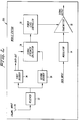
- Figure 2 is a functional block diagram of a mobile station according to the present invention;
- Figure 3 is a detailed functional block diagram of a mobile station for implementing the present invention in a CDMA cellular system;
- Figure 4 is a functional block diagram of a CDMA signal generator for implementing the present invention; and
- Figure 5 is a graphic simulation of a non-linear power control function that may be used to achieve an optimum relationship between uplink and downlink relative power.
- The invention applies to radio communications systems between base stations and a multiplicity of mobiles where the power levels transmitted by each mobile and by the base station may be controlled to provide optimal signal power levels in order to reduce interference in surrounding cells. For purposes of description only, the present invention is described in the context of discrete and continuous transmissions from mobile to base and base to mobile.
- According to Figure 1, a
base station 100 is equipped with transmitters (16a, 16b, 16c...) for transmitting different data signals to a plurality of mobile stations via atransmitter amplifier 17 and anantenna 18. The relative power level of each transmitted signal is determined by apower control unit 14. As will be described in more detail below, thepower control unit 14 determines and sets the power levels for signal transmissions apportioned to each mobile based on the relative power levels measured by thereceivers antenna 10. The sum of all of the signals transmitted by thebase station 100 combine to define a composite signal. - According to Figure 2, a
mobile station 200 is equipped with areceiver 22 which operates in a conventional manner to filter, amplify and demodulate a signal fromantenna 20.Afirst decoder 24 is provided for selectively receiving and decoding its intended signal transmitted from thebase station 100 and measuring its signal strength. Data signals demodulated in thefirst decoder 24 are generated as output data signals for subsequent use. Other signals transmitted from thebase station 100 intended for other mobiles within its cell are received and decoded in asecond decoder 26 where their respective signal strengths are measured. Asignal strength calculator 28 receives the signal strength measurements from both of the first andsecond decoders base station 100. The data input signals to be transmitted from the mobile 200 to thebase station 100 are received in amodulator 34. Atransmitter 32 receives the modulated signal. Based on the transmission power calculated by thesignal strength calculator 28, apower level controller 30 varies the power of thetransmitter 32 to transmit a mobile output signal. - The operation of the control loop of the present invention will now be described. If the
power control unit 14 of thebase station 100 determines that a particular mobile's signal strength is greater (or weaker) than signal strengths received from the other mobiles, thebase station 100power control unit 14 reduces the power of a corresponding transmitter, e.g.,transmitter 16a. That power reduction is implemented not as an instantaneous change but rather as a gradual change from the present power value towards the new target value over a period of time, e.g., 20 msec. - After the mobile 200 measures the received signal strength in the
first decoder 24, thesignal strength calculator 28 determines that the strength of the signal from thebase station 100 to the mobile 200 has been reduced relative to the signal strength previously received. The actual power reduction is determined either by computing the ratio of the signal strength value received by themobile decoder 24 to the mean of the total signal power transmitted to all of the mobiles in the cell, or by determining the position of the signal received by the mobile 200 in a relative signal strength ranking with signals for other mobiles within the cell. - For example, if the mobile's 200 received signal strength had previously been ranked fifth in a signal strength order of all the cell mobiles and is now determined to be sixth, it is clear that the apportioned signal power from the base station to that mobile 200 has been reduced. Thus, the mobile
power level controller 30 changes the target power level for themobile transmitter 32 from a power value P5 to a lower power target value P6. These power values P1, P2, P3..... may be stored in a memory in a predetermined table format. Thepower level controller 30 then decreases the actual value of the transmitted mobile power over a predetermined time period from P5 towards P6. If at the end of that time period, the transmitted mobile power has only reached some intermediate value Pi and new signal strength measurements result in a new target value Pn, then the power level is gradually changed from the current value Pi towards the target value Pn. - Alternatively, if actual signal strength rather than relative signal strength order is used to determine power level changes, the mobile power level controller calculates a ratio r=So/Sm, where So denotes the signal strength of that portion of the base station signal intended for specific mobile 200 and Sm denotes the mean signal strength value of the base station signals intended for other mobiles. From this ratio a new target power level is selected according to a non-linear function P(r) which depends on the ratio r. The exact nature of the non-linear function P(r) depends on the particular communications scenario such as the number of mobile stations supported by each cell, the type of modulation, the frequency re-use pattern, the distribution of mobiles in the cell, the physical geography within the cell, the desired C/I ratio, etc., and may be specified by a predetermined look-up table.
- Thus, the control loop essentially includes the base station detecting power level changes from individual mobiles in its cell as those mobiles move further or closer, behind buildings, etc., and adjusting the power level of the base station transmitter associated with each mobile to minimize the affect of those power level changes. Once a mobile detects that change in base station transmission power level allocated to that mobile, it modifies its transmission power level to match the detected change. No bidirectional messages or signalling between the base station and mobiles is required.
- A preferred embodiment of the present invention for a duplex power control system is described for purposes of illustration in the context of a subtractive CDMA cellular telephone system similar to that disclosed in U.S. Patent Application Serial No. 07/628,359, filed on December 17,1990, assigned to the present assignee. The subject matter of this application is expressly incorporated by reference.
- A
mobile station 200 for implementing this preferred embodiment is illustrated in Figure 3. Aduplexer 52 allows both a receivingamplifier 54 and atransmitter 70 to be connected to anantenna 50 simultaneously. Theamplifier 54 amplifies a received, composite signal which includes signals from the base station to all of the mobile stations within its cell as well as interference. Afilter 56 filters the amplifier output signal to remove extraneous noise. Thefilter 56 output signal, consisting of a coded block of superimposed CDMA signals from thecorresponding base station 100, is divided into its real and imaginary (quadrature or I,Q) components and digitized in a dual-channel A-to-D convertor 58. - A
CDMA signal processor 60 and a signal strength tracker andsorter 62 form aCDMA demodulator 63. TheCDMA processor 60 demodulates the strongest signal from the composite signal and subtracts the demodulated signal from the composite received signal in an iterative demodulation process until all of the coded, mobile signals from thebase station 100 are demodulated. The signal strength values of each demodulated signal code block are sorted in the signal strength tracker andsorter 62 in the order of strongest to weakest signal strength value and used to predict the relative strengths of the signals for the next code block. Adetailed description of the subtractive CDMA demodulation procedure is provided in the above-described patent application which has been incorporated by reference. - The position in signal strength order of that portion of the base station signal intended for a particular mobile is assigned a relative power level value by the signal strength tracker and
sorter 62 and stored in a memory look-up table 64. The signal strength tracker andsorter 62 assigns power levels according to the relative signal strength order. A higher relative signal strength would correspond, for example, to a greater power level value and vice versa. - Each power level in the relative power level order is associated with a particular mobile and each mobile's power level is sent to its
respective power controller 66. If the power level associated with that particular mobile has changed since the last iteration, thepower controller 66 regulates that mobile transmitter's 70 output power towards the new power level value. Thepower controller 66 imposes a time constant on the change from the present power to the newly determined power levelsothatthe base station 100 does not experience sudden step changes in the received power level from that mobile. For example, thepower controller 66 might ramp the power level from the present value to the desired value at a limited rate so that it does not change more than 0.10 decibels between successive code blocks. If a code block has a typical duration of 0.50 msec, the rate of power change may be 200dB per second. This rate is sufficiently high to partially minimize the effects of signal fading. - In an alternative embodiment, rather than using a mobile's position in signal strength order to select the transmitter power in discrete steps, the ratio "r" of the power of that portion of the base station signal So intended for one mobile divided by the total power of all the mobile signals within the cell Sm is used as a continuous power control variable. This continuous variable is transformed through the non-linear function P(r) to obtain the new, desired value of the mobile transmitter power. The non-linearfunction P(r) may be implemented by numerically approximating the continuous variable "r" to a certain number of bits, e.g., 8 bits, and using it to address a look-up table, e.g., having 256 locations. The look-up table representing P(r) is predetermined so that for each of 256 "r" values, a corresponding value P(r) is addressed and retrieved. Greater precision is achieved by increasing the number of bits representing the ratio "r", e.g., 10 bits generates 1024 values stored in the lookup table. Of course, if "r" was truly continuous, a lookup table would be infinitely large.
- It is beyond the scope of this description to provide exhaustive details concerning the determination of the non-linear function used to generate the contents of the look-up table. Such a determination requires complex simulations of the entire duplex communications system. However, the various criteria set forth belowwill enable a person of ordinary skill in the art to develop a suitable, non-linearfunction. The ratio "r" may be expressed either as a power ratio, a voltage ratio, or in dB's, i.e., on a logarithmic scale. A simulation of a non-linear function P(r) for achieving an optimum relationship between uplinkand downlink relative power is illustrated graphically in Fig. 5. The cell is assumed to contain 24 active mobiles numbered 1-24 along the horizontal axis in increasing distance from the base station. X=24 corresponds to the mobile farthest from the base station; X=1 corresponds to the mobiles nearest the base station.
- While the power levels required in the uplink direction from mobile to base station to provide equal power levels at the base station are determined by the fourth power propagation law described above, e.g., the power levels are inversely proportional to the fourth power of the distances from each mobile to its base station, the propagation law which dictates the power levels required for the downlink direction to provide equal signal quality at each mobile must account for neighboring cell interference. It is the difference between the uplink and downlink propagation laws caused by neighboring cell interference that requires a non-linearfunction to translate relative signal strength for downlink transmissions to required transmitter power on uplink transmissions.
- The graph in Fig. 5 illustrates the non-linear correspondence between distribution of base station power to mobiles on the downlink and mobile transmitter power required uplink to the base station. The curve labelled Power Share shows for the particular system simulated the proportion of the total base station transmitter power each mobile should receive (in dB below total transmitted base station power) to achieve equality in signal quality at each mobile. Consequently, mobile 1 receives -42dB of the total power while mobile 24 receives -8dB, a difference of 34dB.
- On the other hand, mobile 24 is 24 further times away than mobile 1, assuming a uniform area distribution of mobiles, and based on the fourth power radius law referenced above, the mobile 24 needs to transmit (24)2 times as much power as mobile 1 which is equivalent to 28dB. Likewise mobile 10 gets 22dB more base station power than mobile 1 but should transmit 20dB more back to the base station, etc. Thus, each mobile adjusts its transmitter power in response to changes of signal strength intended forthat mobile received from the base station according to the non-linear function P(r).
- Another objective of the present invention in adjusting mobile transmitter power is to achieve equal signal-to-interference ratios (C/I) at the base station for all the mobiles simultaneously with equal signal-to-interference ratios (C/I) at all of the mobiles with respect to signals from the base station. A problem affecting achievement of that objective is that the instantaneous signal strengths of all mobiles varies because of multipath or Rayleigh fading on their respective, uncorrelated signal paths. In systems using subtractive CDMA demodulation, signals from mobiles near the base station exhibiting a single, dominant propagation path (low echoes) have the strongest signal strengths and therefore should be demodulated and removed from the composite signal first. Signals from more distant mobiles being more likely to be received with multiple paths (delayed echoes from reflections from mountains, buildings, etc.) should be removed subsequently. Accordingly, in the subtractive CDMA embodiment of the present invention, the base station sets one target signal strength above the mean for mobiles likely to have multiple paths and a second target signal strength below the mean for those mobiles less likely to have multiple paths.
- Given the unpredictable nature of the interference and multipath fading problems described above, the contents of the non-linear power function look-up table 64, being based on theoretical calculations, must often be modified in light of practical experience for optimal results. The present invention provides for the look-up table 64 to be changed by a command from the base station included in the data received by the mobile as a digital control message. While the modification might be an overall scaling factor in the simplest case, it might also involve the selective modification of certain elements or a complete rewriting of the entire table. In situations where target signal strengths are not specified by the base station or are unnecessary, a default table look-up may also be provided in each mobile station.
- When discontinuous transmission (DTX) is used in conjunction with the duplex power control system of the present invention, normally only the mobile transmitter associated with the active speaker is transmitting. Therefore, during much of a normal voice conversation a communications link exists only in one direction, and the power control loop of the present invention between the mobile and the base station is broken. Of course, it is possible for a mobile to formulate its transmitter power based on past signal strength measurements from previous transmissions from the base station, but those measurements may be too old to be of use and no compensation for Rayleigh or log normal fading is obtained.
- The use of DTX in combination with the present invention in the system illustrated in Figure 3 will now be described in more detail in conjunction with Figure 4. The
CDMAsignal generator 68, which is used either in thebase station 100 or each mobile 200, uses aspeech encoder 80 for encoding the speech inputwa- veform in typically 20msec blocks into a coded block of typically 280 data bits. Each 20msec block generated by thespeech encoder 80 either contains speech information or silence (no speech). Anorthogonal block encoder 82 encodes groups of bits, typically seven bits, of the coded block into code words, typically 128 bits long. Ascrambler 84 using a unique code for each mobile insures that code word sequences differ for each mobile. - Of forty-two code words transmitted per 20 msec, forty code words typically represent one speech block. The code words in each block are staggered by a
code word generator 86 one code word apart in order to distinguish between the signals destined for different mobiles. The benefit of staggering is that the staggered code words appear for each mobile signal at different time positions and maintain signal strength measurements between each mobile and the base station during otherwise silent transmission periods. Also, peaks in receiver activity to demodulate and decode the code words are avoided. - At times when there is no speech to transmit because of a silent period, only two (or some small number) code words in a predetermined position within the 40-word block are transmitted. When the base station or mobile receiver detects these initial code words indicating a silence block, the receiver ignores the rest of the block. In this way, considerable signal processing resources are conserved. In addition, this staggered code word transmission technique provides the mobile and base station receiver with at least one sample of signal strength for each signal every 20msec, thus enabling the power control loop of the present invention to remain in continuous operation.
- The invention has been described in terms of specific embodiments to facilitate understanding. The above embodiments, however, are illustrative rather than limitative. It will be readily apparent to one of ordinary skill in the art that departures may be made from the specific embodiments shown above without departing from the essential spirit and scope of the invention. Therefore, the invention should not be regarded as limited to the above examples, but should be regarded instead as being fully commensurate in scope with the following claims.
Claims (33)
Applications Claiming Priority (2)
| Application Number | Priority Date | Filing Date | Title |
|---|---|---|---|
| US866554 | 1978-01-03 | ||
| US07/866,554 US5345598A (en) | 1992-04-10 | 1992-04-10 | Duplex power control system in a communication network |
Publications (3)
| Publication Number | Publication Date |
|---|---|
| EP0565505A2 true EP0565505A2 (en) | 1993-10-13 |
| EP0565505A3 EP0565505A3 (en) | 1995-08-30 |
| EP0565505B1 EP0565505B1 (en) | 2001-08-22 |
Family
ID=25347858
Family Applications (1)
| Application Number | Title | Priority Date | Filing Date |
|---|---|---|---|
| EP93850067A Expired - Lifetime EP0565505B1 (en) | 1992-04-10 | 1993-04-01 | Duplex power control in a cellular mobile radio telephone system |
Country Status (16)
| Country | Link |
|---|---|
| US (1) | US5345598A (en) |
| EP (1) | EP0565505B1 (en) |
| JP (1) | JP3369176B2 (en) |
| KR (1) | KR100263290B1 (en) |
| AU (1) | AU664751B2 (en) |
| BR (1) | BR9305476A (en) |
| CA (1) | CA2111008C (en) |
| DE (1) | DE69330621T2 (en) |
| ES (1) | ES2161710T3 (en) |
| FI (1) | FI110648B (en) |
| HK (1) | HK1014313A1 (en) |
| MX (1) | MX9301959A (en) |
| NZ (1) | NZ251899A (en) |
| SG (1) | SG48846A1 (en) |
| TW (1) | TW214618B (en) |
| WO (1) | WO1993021700A1 (en) |
Cited By (21)
| Publication number | Priority date | Publication date | Assignee | Title |
|---|---|---|---|---|
| EP0668664A1 (en) * | 1994-01-31 | 1995-08-23 | Matsushita Electric Industrial Co., Ltd. | CDMA/TDD radio communication system |
| WO1996007246A1 (en) * | 1994-08-24 | 1996-03-07 | Nokia Telecommunications Oy | Power control method in a cellular communication system, and a receiver |
| WO1996038935A1 (en) * | 1995-06-02 | 1996-12-05 | Dsc Communications Corporation | Controlling transmitter gain in a wireless telecommunications system |
| WO1998010530A2 (en) * | 1996-09-05 | 1998-03-12 | Airnet Communications Corporation | Optimizing forward link transmit power |
| WO1998026518A1 (en) * | 1996-12-11 | 1998-06-18 | Samsung Electronics Co., Ltd. | A circuit and method for controlling the power used by a portable radiotelephone |
| EP0851604A2 (en) * | 1996-12-24 | 1998-07-01 | Lucent Technologies Inc. | Microcell load measurement using feedback control |
| EP0856955A2 (en) * | 1997-01-29 | 1998-08-05 | YRP Mobile Telecommunications Key Technology Research Laboratories Co., Ltd. | CDMA power control system |
| WO1998053558A2 (en) * | 1997-05-22 | 1998-11-26 | Siemens Aktiengesellschaft | Method and device for adjusting transmitter power for linking a base station and a mobile station in a radio communication system |
| DE19721500C1 (en) * | 1997-05-22 | 1999-04-15 | Siemens Ag | Method and arrangement for processing control signals in mobile station of mobile radio system |
| EP0718984A3 (en) * | 1994-12-23 | 2000-04-05 | Nokia Mobile Phones Ltd. | Apparatus and method for power level control in radio communication system |
| EP0718985A3 (en) * | 1994-12-23 | 2000-04-05 | Nokia Mobile Phones Ltd. | Apparatus and method for power level control in radio communications system |
| EP0680159A3 (en) * | 1994-04-28 | 2000-05-24 | AT&T Corp. | Method and apparatus for controlling the transmission power of different types of wireless devices in a CDMA system |
| US6198911B1 (en) | 1995-06-02 | 2001-03-06 | Airspan Networks, Inc. | Controlling transmitter gain in a wireless telecommunications system |
| EP1097518A1 (en) * | 1998-07-10 | 2001-05-09 | Motorola, Inc. | Method and system for allocating transmit power to subscriber units in a wireless communications system |
| EP0856439A4 (en) * | 1996-09-03 | 2001-06-27 | Toyota Motor Co Ltd | Side air bag-carrying seat structure |
| CN1071985C (en) * | 1995-10-11 | 2001-09-26 | 日本电气株式会社 | Mobile communication system capable of effectively carrying out hand-over control |
| EP1322048A1 (en) * | 2001-12-20 | 2003-06-25 | Nec Corporation | Downlink transmission power controlling method and base station apparatus |
| GB2418105A (en) * | 2004-09-13 | 2006-03-15 | Fujitsu Ltd | Relative indicators used for scheduling of uplink transmissions |
| EP0941584B1 (en) * | 1997-08-14 | 2006-10-04 | Nokia Corporation | Method of optimizing transmission, and transmitter |
| US7706830B2 (en) | 1996-06-27 | 2010-04-27 | Interdigital Technology Corporation | Method and subscriber unit for performing an access procedure |
| CN110234157A (en) * | 2019-04-23 | 2019-09-13 | 广州南方卫星导航仪器有限公司 | A kind of control method that data radio station is adaptive |
Families Citing this family (92)
| Publication number | Priority date | Publication date | Assignee | Title |
|---|---|---|---|---|
| US5446756A (en) * | 1990-03-19 | 1995-08-29 | Celsat America, Inc. | Integrated cellular communications system |
| US5550809A (en) * | 1992-04-10 | 1996-08-27 | Ericsson Ge Mobile Communications, Inc. | Multiple access coding using bent sequences for mobile radio communications |
| DE69325844T2 (en) * | 1992-04-17 | 2000-08-31 | Ericsson Telefon Ab L M | Mobile-assisted handoff with code division multiple access |
| EP0631382B1 (en) * | 1993-06-25 | 2001-05-09 | Siemens Aktiengesellschaft | Method for optimising the automatic adjustment of an amplifier in an rf-receiver |
| US5870393A (en) * | 1995-01-20 | 1999-02-09 | Hitachi, Ltd. | Spread spectrum communication system and transmission power control method therefor |
| JP3457357B2 (en) * | 1993-07-23 | 2003-10-14 | 株式会社日立製作所 | Spread spectrum communication system, transmission power control method, mobile terminal device, and base station |
| GB2281477A (en) * | 1993-08-20 | 1995-03-01 | American Telephone & Telegraph | Operation of a CDMA net |
| FI108179B (en) * | 1993-09-03 | 2001-11-30 | Nokia Networks Oy | A method for controlling transmit power in a radiotelephone system and a radiotelephone exchange |
| US5530638A (en) * | 1993-09-24 | 1996-06-25 | At&T Corp. | Multi-resonant electronic power converter with a wide dynamic range |
| IT1261365B (en) * | 1993-12-02 | 1996-05-20 | Cselt Centro Studi Lab Telecom | PROCEDURE AND DEVICE FOR THE POWER CONTROL IN THE MOBILE BASE-HALF STATION ROUTE OF A RADIO-MOBILE SYSTEM WITH ACCESS TO CODE DIVISION |
| DE4343765C2 (en) * | 1993-12-21 | 2003-11-13 | Detecon Gmbh | Control system for radio coverage in a cellular, digital mobile communication system |
| US5490288A (en) * | 1994-02-08 | 1996-02-06 | Motorola, Inc. | Method for determining low signal quality communications |
| JP2974274B2 (en) * | 1994-05-12 | 1999-11-10 | エヌ・ティ・ティ移動通信網株式会社 | Transmission power control method and transmission power control device |
| CN1105429C (en) * | 1994-06-03 | 2003-04-09 | 摩托罗拉公司 | Method and apparatus for subscriber power level adjustment in communication system |
| US5579306A (en) * | 1994-09-01 | 1996-11-26 | Ericsson Inc. | Time and frequency slot allocation system and method |
| US5649303A (en) * | 1994-09-02 | 1997-07-15 | Motorola, Inc. | Method and apparatus for reducing interference among communication systems |
| GB2294168A (en) * | 1994-10-15 | 1996-04-17 | Nokia Telecommunications Oy | Multi-channel transmitters for radio telephone base stations |
| US5787336A (en) * | 1994-11-08 | 1998-07-28 | Space Systems/Loral, Inc. | Satellite communication power management system |
| US5689815A (en) * | 1995-05-04 | 1997-11-18 | Oki Telecom, Inc. | Saturation prevention system for radio telephone with open and closed loop power control systems |
| US5697056A (en) * | 1995-05-08 | 1997-12-09 | Motorola, Inc. | Communication system in which radio subscriber units mitigate interference |
| FI98108C (en) * | 1995-05-17 | 1997-04-10 | Nokia Mobile Phones Ltd | Method for assessing connection quality and receiver |
| US5761622A (en) * | 1995-05-18 | 1998-06-02 | Ericsson Inc. | Method and apparatus for controlling operation of a portable or mobile battery-operated radios |
| US6697350B2 (en) | 1995-06-30 | 2004-02-24 | Interdigital Technology Corporation | Adaptive vector correlator for spread-spectrum communications |
| US6816473B2 (en) | 1995-06-30 | 2004-11-09 | Interdigital Technology Corporation | Method for adaptive forward power control for spread-spectrum communications |
| ZA965340B (en) * | 1995-06-30 | 1997-01-27 | Interdigital Tech Corp | Code division multiple access (cdma) communication system |
| US7072380B2 (en) | 1995-06-30 | 2006-07-04 | Interdigital Technology Corporation | Apparatus for initial power control for spread-spectrum communications |
| US7929498B2 (en) | 1995-06-30 | 2011-04-19 | Interdigital Technology Corporation | Adaptive forward power control and adaptive reverse power control for spread-spectrum communications |
| US7020111B2 (en) | 1996-06-27 | 2006-03-28 | Interdigital Technology Corporation | System for using rapid acquisition spreading codes for spread-spectrum communications |
| US6049535A (en) * | 1996-06-27 | 2000-04-11 | Interdigital Technology Corporation | Code division multiple access (CDMA) communication system |
| US6940840B2 (en) | 1995-06-30 | 2005-09-06 | Interdigital Technology Corporation | Apparatus for adaptive reverse power control for spread-spectrum communications |
| US6801516B1 (en) | 1995-06-30 | 2004-10-05 | Interdigital Technology Corporation | Spread-spectrum system for assigning information signals having different data rates |
| US7123600B2 (en) | 1995-06-30 | 2006-10-17 | Interdigital Technology Corporation | Initial power control for spread-spectrum communications |
| US6788662B2 (en) | 1995-06-30 | 2004-09-07 | Interdigital Technology Corporation | Method for adaptive reverse power control for spread-spectrum communications |
| US6885652B1 (en) | 1995-06-30 | 2005-04-26 | Interdigital Technology Corporation | Code division multiple access (CDMA) communication system |
| JP2798012B2 (en) * | 1995-07-14 | 1998-09-17 | 日本電気株式会社 | Base station transmission power control apparatus and method |
| US5678208A (en) * | 1995-07-19 | 1997-10-14 | Motorola, Inc. | Transmission system |
| US5894473A (en) * | 1996-02-29 | 1999-04-13 | Ericsson Inc. | Multiple access communications system and method using code and time division |
| DE69705356T2 (en) * | 1996-05-17 | 2002-05-02 | Motorola Ltd | Method and device for weighting a transmission path |
| JP2839014B2 (en) * | 1996-07-05 | 1998-12-16 | 日本電気株式会社 | Transmission power control method for code division multiplexing cellular system |
| US6067446A (en) * | 1996-07-11 | 2000-05-23 | Telefonaktiebolaget Lm Ericsson | Power presetting in a radio communication system |
| JP3818702B2 (en) | 1996-08-07 | 2006-09-06 | 松下電器産業株式会社 | CDMA radio transmission system, transmission power control apparatus and transmission power control measuring apparatus used in the system |
| CA2183139C (en) * | 1996-08-12 | 2003-11-18 | Qiang Shen | Closed-loop power control scheme with prediction of power control commands and multi-level transmitted power adjustment |
| US6473602B1 (en) * | 1996-10-28 | 2002-10-29 | Ericsson Inc. | Mobile assisted handoff in radiocommunication systems |
| KR100227780B1 (en) * | 1996-10-29 | 1999-11-01 | 정선종 | Method and apparatus for measuring received signal intensity of cdma user |
| US6360079B2 (en) | 1997-02-12 | 2002-03-19 | Interdigital Technology Corporation | Global channel power control to minimize spillover in a wireless communication environment |
| US5842114A (en) | 1997-02-12 | 1998-11-24 | Interdigital Technology Corporation | Global channel power control to minimize spillover in a wireless communication environment |
| US6236863B1 (en) | 1997-03-31 | 2001-05-22 | Oki Telecom, Inc. | Comprehensive transmitter power control system for radio telephones |
| US6829226B1 (en) * | 1997-04-04 | 2004-12-07 | Ericsson Inc. | Power control for a mobile terminal in a satellite communication system |
| US6072990A (en) * | 1997-05-08 | 2000-06-06 | Lucent Technologies, Inc. | Transmitter-receiver pair for wireless network power-code operating point is determined based on error rate |
| US6308080B1 (en) * | 1997-05-16 | 2001-10-23 | Texas Instruments Incorporated | Power control in point-to-multipoint systems |
| US6253077B1 (en) * | 1997-05-16 | 2001-06-26 | Texas Instruments Incorporated | Downstream power control in point-to-multipoint systems |
| US6259927B1 (en) | 1997-06-06 | 2001-07-10 | Telefonaktiebolaget Lm Ericsson | Transmit power control in a radio communication system |
| US6173162B1 (en) | 1997-06-16 | 2001-01-09 | Telefonaktiebolaget Lm Ericsson (Publ) | Multiple code channel power control in a radio communication system |
| US6185431B1 (en) * | 1997-06-18 | 2001-02-06 | Oki Telecom, Inc. | Mobile station closed loop output power stability system for weak signal conditions |
| US6104933A (en) * | 1997-06-23 | 2000-08-15 | Telefonaktiebolaget Lm Ericsson | Method and apparatus for control of base stations in macro diversity radio systems |
| US6128506A (en) * | 1997-09-24 | 2000-10-03 | Telefonaktiebolaget Lm Ericsson | Integrated power control and congestion control in a communication system |
| US6028851A (en) * | 1997-09-26 | 2000-02-22 | Telefonaktiebolaget L M Ericsson (Publ) | System and method for mobile assisted admission control |
| US6169907B1 (en) * | 1997-10-21 | 2001-01-02 | Interwave Communications International Ltd. | Power control of remote communication devices |
| CA2292569C (en) * | 1998-04-25 | 2003-04-08 | Samsung Electronics Co., Ltd. | Power level arbitration between base station and mobile station in mobile communication system |
| US6334057B1 (en) * | 1998-06-30 | 2001-12-25 | Telefonaktiebolaget Lm Ericsson (Publ) | Channel allocation in a telecommunications system with asymmetric uplink and downlink traffic |
| US6275478B1 (en) * | 1998-07-10 | 2001-08-14 | Qualcomm Incorporated | Methods and apparatuses for fast power control of signals transmitted on a multiple access channel |
| BR9912611A (en) * | 1998-07-30 | 2001-10-09 | Airnet Communications Corp | Broadband power management (power alignment) in a broadband multiple carrier base station transceiver system |
| US6512925B1 (en) * | 1998-12-03 | 2003-01-28 | Qualcomm, Incorporated | Method and apparatus for controlling transmission power while in soft handoff |
| US6405018B1 (en) | 1999-01-11 | 2002-06-11 | Metawave Communications Corporation | Indoor distributed microcell |
| DE69933654T2 (en) * | 1999-01-16 | 2007-08-23 | Koninklijke Philips Electronics N.V. | Radio communication system |
| US6535723B1 (en) * | 1999-03-15 | 2003-03-18 | Lucent Technologies Inc. | Method of power control for a wireless communication system having multiple information rates |
| US6731948B1 (en) * | 1999-05-12 | 2004-05-04 | Samsung Electronics Co., Ltd. | Method for supporting a discontinuous transmission mode in a base station in a mobile communication system |
| US6631123B1 (en) * | 1999-09-14 | 2003-10-07 | Lucent Technologies Inc. | Method of improving user access performance by adjusting power of user probe signal |
| US6529494B1 (en) * | 1999-09-21 | 2003-03-04 | Telefonaktiebolaget Lm Ericsson (Publ) | Downlink timeslot power control in a time division multiple access system |
| CN1241334C (en) | 1999-09-30 | 2006-02-08 | 艾利森电话股份有限公司 | Transmit power control |
| DE19958383A1 (en) | 1999-12-03 | 2001-06-07 | Bosch Gmbh Robert | Method for regulating the transmission power of a transmitting station and receiving station for carrying out the method |
| US6553016B1 (en) | 1999-12-20 | 2003-04-22 | Telfonaktiebolaget Lm Ericsson (Publ) | Downlink power control at soft handover |
| JP3389951B2 (en) * | 2000-02-07 | 2003-03-24 | 日本電気株式会社 | CDMA mobile communication system and downlink transmission power control method in the CDMA mobile communication system |
| US20010040877A1 (en) * | 2000-05-09 | 2001-11-15 | Motorola, Inc. | Method of dynamic transmit scheduling using channel quality feedback |
| US6873613B1 (en) * | 2000-10-16 | 2005-03-29 | Ericsson Inc. | Methods for wirelessly communicating time division multiple access (TDMA) data using adaptive multiplexing and coding |
| US6804524B1 (en) * | 2000-11-21 | 2004-10-12 | Openwave Systems Inc. | System and method for the acquisition of automobile traffic data through wireless networks |
| US8275324B2 (en) * | 2001-11-02 | 2012-09-25 | Qualcomm Incorporated | Method and apparatus for predicting received signal strength in a communication system |
| US6954622B2 (en) * | 2002-01-29 | 2005-10-11 | L-3 Communications Corporation | Cooperative transmission power control method and system for CDMA communication systems |
| WO2003084090A1 (en) * | 2002-04-03 | 2003-10-09 | Telefonaktiebolaget L M Ericsson (Publ) | Power control in mobile communication system |
| US7869822B2 (en) | 2003-02-24 | 2011-01-11 | Autocell Laboratories, Inc. | Wireless network apparatus and system field of the invention |
| US20040202122A1 (en) * | 2003-02-24 | 2004-10-14 | Floyd Backes | Wireless access point protocol program |
| US8411616B2 (en) | 2005-11-03 | 2013-04-02 | Piccata Fund Limited Liability Company | Pre-scan for wireless channel selection |
| US7801547B2 (en) * | 2005-12-22 | 2010-09-21 | Telefonaktiebolaget L M Ericsson (Publ) | System and method for determining downlink signaling power in a radio communication network |
| DE102006008463A1 (en) * | 2006-02-17 | 2007-08-23 | Kaco Gmbh + Co. Kg | Test device for detecting the vapor emission at at least one leakage point, preferably in mechanical seals, in particular in the automotive sector |
| WO2008085181A1 (en) * | 2007-01-12 | 2008-07-17 | E28 Limited | Method of controlling an end-user device in communication with a plurality of wireless networks |
| KR101558304B1 (en) * | 2008-11-20 | 2015-10-07 | 삼성전자주식회사 | Method and apparatus for improving unbalance of service of cell edge in wireless local area network |
| US8478213B2 (en) * | 2011-10-14 | 2013-07-02 | Research In Motion Limited | Methods and apparatus for power control |
| US10051616B2 (en) * | 2014-10-07 | 2018-08-14 | Massachusetts Institute Of Technology | Multiuser detection for high capacity cellular downlink |
| US9432131B2 (en) * | 2014-11-28 | 2016-08-30 | Telefonaktiebolaget Lm Ericsson (Publ) | Method and apparatus for handling inter-modulation interference in a network node capable of FDD communications |
| US9668268B2 (en) | 2015-02-06 | 2017-05-30 | Telefonaktiebolaget Lm Ericsson (Publ) | Method, computer program, controller and network node |
| US9693360B2 (en) | 2015-03-25 | 2017-06-27 | Telefonaktiebolaget Lm Ericsson (Publ) | Methods, computer programs, network node and transceiver device |
| GB2556864B (en) | 2016-07-29 | 2021-04-14 | Gelliner Ltd | Payment confirmation system and method |
Citations (4)
| Publication number | Priority date | Publication date | Assignee | Title |
|---|---|---|---|---|
| WO1991002436A1 (en) * | 1989-07-31 | 1991-02-21 | Telecom Securicor Cellular Radio Limited | Cellular radio system |
| WO1991007037A1 (en) * | 1989-11-07 | 1991-05-16 | Qualcomm Incorporated | Method and apparatus for controlling transmission power in a cdma cellular mobile telephone system |
| EP0462952A1 (en) * | 1990-06-21 | 1991-12-27 | Telefonaktiebolaget L M Ericsson | A method for regulating power in a digital mobile telephony system |
| GB2249926A (en) * | 1990-09-06 | 1992-05-20 | Ericsson Telefon Ab L M | Cellular mobile radio system |
Family Cites Families (14)
| Publication number | Priority date | Publication date | Assignee | Title |
|---|---|---|---|---|
| US4134071A (en) * | 1971-07-19 | 1979-01-09 | Licentia Patent-Verwaltungs-G.M.B.H. | SSMA Data transmission system |
| US4293953A (en) * | 1979-12-28 | 1981-10-06 | The United States Of America As Represented By The Secretary Of The Army | Bi-orthogonal PCM communications system employing multiplexed noise codes |
| US4644560A (en) * | 1982-08-13 | 1987-02-17 | Hazeltine Corporation | Intranetwork code division multiple access communication system |
| US4470138A (en) * | 1982-11-04 | 1984-09-04 | The United States Of America As Represented By The Secretary Of The Army | Non-orthogonal mobile subscriber multiple access system |
| US4901307A (en) * | 1986-10-17 | 1990-02-13 | Qualcomm, Inc. | Spread spectrum multiple access communication system using satellite or terrestrial repeaters |
| CH676179A5 (en) * | 1988-09-29 | 1990-12-14 | Ascom Zelcom Ag | |
| US4930140A (en) * | 1989-01-13 | 1990-05-29 | Agilis Corporation | Code division multiplex system using selectable length spreading code sequences |
| JPH02215238A (en) * | 1989-02-15 | 1990-08-28 | Matsushita Electric Ind Co Ltd | Mobile radio equipment |
| US4930139A (en) * | 1989-05-31 | 1990-05-29 | O'neill Communications, Inc. | Spread spectrum communication system |
| US5101501A (en) * | 1989-11-07 | 1992-03-31 | Qualcomm Incorporated | Method and system for providing a soft handoff in communications in a cdma cellular telephone system |
| US5109390A (en) * | 1989-11-07 | 1992-04-28 | Qualcomm Incorporated | Diversity receiver in a cdma cellular telephone system |
| US5022049A (en) * | 1989-11-21 | 1991-06-04 | Unisys Corp. | Multiple access code acquisition system |
| JPH03265314A (en) * | 1990-03-15 | 1991-11-26 | Nippon Telegr & Teleph Corp <Ntt> | Transmission power control system |
| US5103459B1 (en) * | 1990-06-25 | 1999-07-06 | Qualcomm Inc | System and method for generating signal waveforms in a cdma cellular telephone system |
-
1992
- 1992-04-10 US US07/866,554 patent/US5345598A/en not_active Expired - Lifetime
-
1993
- 1993-04-01 SG SG1996002865A patent/SG48846A1/en unknown
- 1993-04-01 EP EP93850067A patent/EP0565505B1/en not_active Expired - Lifetime
- 1993-04-01 DE DE69330621T patent/DE69330621T2/en not_active Expired - Lifetime
- 1993-04-01 ES ES93850067T patent/ES2161710T3/en not_active Expired - Lifetime
- 1993-04-02 TW TW082102460A patent/TW214618B/en not_active IP Right Cessation
- 1993-04-05 MX MX9301959A patent/MX9301959A/en not_active IP Right Cessation
- 1993-04-08 AU AU40268/93A patent/AU664751B2/en not_active Ceased
- 1993-04-08 WO PCT/US1993/003302 patent/WO1993021700A1/en active IP Right Grant
- 1993-04-08 KR KR1019930703852A patent/KR100263290B1/en not_active IP Right Cessation
- 1993-04-08 CA CA002111008A patent/CA2111008C/en not_active Expired - Fee Related
- 1993-04-08 NZ NZ251899A patent/NZ251899A/en unknown
- 1993-04-08 BR BR9305476A patent/BR9305476A/en not_active IP Right Cessation
- 1993-04-08 JP JP51847293A patent/JP3369176B2/en not_active Expired - Lifetime
- 1993-12-09 FI FI935523A patent/FI110648B/en active
-
1998
- 1998-12-24 HK HK98115618A patent/HK1014313A1/en not_active IP Right Cessation
Patent Citations (4)
| Publication number | Priority date | Publication date | Assignee | Title |
|---|---|---|---|---|
| WO1991002436A1 (en) * | 1989-07-31 | 1991-02-21 | Telecom Securicor Cellular Radio Limited | Cellular radio system |
| WO1991007037A1 (en) * | 1989-11-07 | 1991-05-16 | Qualcomm Incorporated | Method and apparatus for controlling transmission power in a cdma cellular mobile telephone system |
| EP0462952A1 (en) * | 1990-06-21 | 1991-12-27 | Telefonaktiebolaget L M Ericsson | A method for regulating power in a digital mobile telephony system |
| GB2249926A (en) * | 1990-09-06 | 1992-05-20 | Ericsson Telefon Ab L M | Cellular mobile radio system |
Cited By (37)
| Publication number | Priority date | Publication date | Assignee | Title |
|---|---|---|---|---|
| EP0668664A1 (en) * | 1994-01-31 | 1995-08-23 | Matsushita Electric Industrial Co., Ltd. | CDMA/TDD radio communication system |
| USRE37870E1 (en) | 1994-01-31 | 2002-10-08 | Matsushita Electric Industrial Co., Ltd. | CDMA/TDD radio communication system |
| US5559789A (en) * | 1994-01-31 | 1996-09-24 | Matsushita Electric Industrial Co., Ltd. | CDMA/TDD Radio Communication System |
| EP0680159A3 (en) * | 1994-04-28 | 2000-05-24 | AT&T Corp. | Method and apparatus for controlling the transmission power of different types of wireless devices in a CDMA system |
| AU697903B2 (en) * | 1994-08-24 | 1998-10-22 | Nokia Telecommunications Oy | Power control method in a cellular communication system, and a receiver |
| US5898740A (en) * | 1994-08-24 | 1999-04-27 | Nokia Telecommunications Oy | Power control method in a cellular communication system, and a receiver |
| WO1996007246A1 (en) * | 1994-08-24 | 1996-03-07 | Nokia Telecommunications Oy | Power control method in a cellular communication system, and a receiver |
| CN1085912C (en) * | 1994-08-24 | 2002-05-29 | 诺基亚电信公司 | Power control method in a cellular communication system, and a receiver |
| EP0718985A3 (en) * | 1994-12-23 | 2000-04-05 | Nokia Mobile Phones Ltd. | Apparatus and method for power level control in radio communications system |
| EP0718984A3 (en) * | 1994-12-23 | 2000-04-05 | Nokia Mobile Phones Ltd. | Apparatus and method for power level control in radio communication system |
| US6198911B1 (en) | 1995-06-02 | 2001-03-06 | Airspan Networks, Inc. | Controlling transmitter gain in a wireless telecommunications system |
| WO1996038935A1 (en) * | 1995-06-02 | 1996-12-05 | Dsc Communications Corporation | Controlling transmitter gain in a wireless telecommunications system |
| CN1071985C (en) * | 1995-10-11 | 2001-09-26 | 日本电气株式会社 | Mobile communication system capable of effectively carrying out hand-over control |
| US8009636B2 (en) | 1996-06-27 | 2011-08-30 | Interdigital Technology Corporation | Method and apparatus for performing an access procedure |
| US7706830B2 (en) | 1996-06-27 | 2010-04-27 | Interdigital Technology Corporation | Method and subscriber unit for performing an access procedure |
| US7873328B2 (en) | 1996-06-27 | 2011-01-18 | Interdigital Technology Corporation | Subscriber unit for performing an access procedure |
| EP0856439A4 (en) * | 1996-09-03 | 2001-06-27 | Toyota Motor Co Ltd | Side air bag-carrying seat structure |
| WO1998010530A3 (en) * | 1996-09-05 | 1998-05-28 | Airnet Communications Corp | Optimizing forward link transmit power |
| WO1998010530A2 (en) * | 1996-09-05 | 1998-03-12 | Airnet Communications Corporation | Optimizing forward link transmit power |
| AU715984B2 (en) * | 1996-12-11 | 2000-02-10 | Samsung Electronics Co., Ltd. | A circuit and method for controlling the power used by a portable radiotelephone |
| WO1998026518A1 (en) * | 1996-12-11 | 1998-06-18 | Samsung Electronics Co., Ltd. | A circuit and method for controlling the power used by a portable radiotelephone |
| EP0851604A2 (en) * | 1996-12-24 | 1998-07-01 | Lucent Technologies Inc. | Microcell load measurement using feedback control |
| EP0851604A3 (en) * | 1996-12-24 | 2000-06-14 | Lucent Technologies Inc. | Microcell load measurement using feedback control |
| EP0856955A3 (en) * | 1997-01-29 | 2000-09-06 | YRP Mobile Telecommunications Key Technology Research Laboratories Co., Ltd. | CDMA power control system |
| EP0856955A2 (en) * | 1997-01-29 | 1998-08-05 | YRP Mobile Telecommunications Key Technology Research Laboratories Co., Ltd. | CDMA power control system |
| US6385183B1 (en) | 1997-01-29 | 2002-05-07 | Yrp Mobile Telecommunications Key Technology Research Laboratories Co., Ltd. | CDMA power control system |
| US6230023B1 (en) | 1997-05-22 | 2001-05-08 | Siemens Aktiengesellschaft | Method and device for a transmit power control for connections between a base station and mobile stations of a radio communications system |
| WO1998053558A3 (en) * | 1997-05-22 | 1999-06-10 | Siemens Ag | Method and device for adjusting transmitter power for linking a base station and a mobile station in a radio communication system |
| DE19721500C1 (en) * | 1997-05-22 | 1999-04-15 | Siemens Ag | Method and arrangement for processing control signals in mobile station of mobile radio system |
| WO1998053558A2 (en) * | 1997-05-22 | 1998-11-26 | Siemens Aktiengesellschaft | Method and device for adjusting transmitter power for linking a base station and a mobile station in a radio communication system |
| EP0941584B1 (en) * | 1997-08-14 | 2006-10-04 | Nokia Corporation | Method of optimizing transmission, and transmitter |
| EP1097518A1 (en) * | 1998-07-10 | 2001-05-09 | Motorola, Inc. | Method and system for allocating transmit power to subscriber units in a wireless communications system |
| EP1097518A4 (en) * | 1998-07-10 | 2004-06-23 | Motorola Inc | Method and system for allocating transmit power to subscriber units in a wireless communications system |
| EP1322048A1 (en) * | 2001-12-20 | 2003-06-25 | Nec Corporation | Downlink transmission power controlling method and base station apparatus |
| US7218945B2 (en) | 2001-12-20 | 2007-05-15 | Nec Corporation | Transmission power controlling method and base station apparatus |
| GB2418105A (en) * | 2004-09-13 | 2006-03-15 | Fujitsu Ltd | Relative indicators used for scheduling of uplink transmissions |
| CN110234157A (en) * | 2019-04-23 | 2019-09-13 | 广州南方卫星导航仪器有限公司 | A kind of control method that data radio station is adaptive |
Also Published As
| Publication number | Publication date |
|---|---|
| AU664751B2 (en) | 1995-11-30 |
| SG48846A1 (en) | 1998-05-18 |
| HK1014313A1 (en) | 1999-09-24 |
| DE69330621T2 (en) | 2002-06-13 |
| FI935523A (en) | 1993-12-09 |
| US5345598A (en) | 1994-09-06 |
| CA2111008A1 (en) | 1993-10-28 |
| EP0565505B1 (en) | 2001-08-22 |
| JPH06511129A (en) | 1994-12-08 |
| EP0565505A3 (en) | 1995-08-30 |
| MX9301959A (en) | 1993-10-01 |
| TW214618B (en) | 1993-10-11 |
| KR100263290B1 (en) | 2000-08-01 |
| FI110648B (en) | 2003-02-28 |
| FI935523A0 (en) | 1993-12-09 |
| NZ251899A (en) | 1996-09-25 |
| AU4026893A (en) | 1993-11-18 |
| CA2111008C (en) | 2003-01-14 |
| WO1993021700A1 (en) | 1993-10-28 |
| DE69330621D1 (en) | 2001-09-27 |
| ES2161710T3 (en) | 2001-12-16 |
| JP3369176B2 (en) | 2003-01-20 |
| KR940701608A (en) | 1994-05-28 |
| BR9305476A (en) | 1994-10-11 |
Similar Documents
| Publication | Publication Date | Title |
|---|---|---|
| US5345598A (en) | Duplex power control system in a communication network | |
| US6535723B1 (en) | Method of power control for a wireless communication system having multiple information rates | |
| EP0990314B1 (en) | Multiple code channel power control in a radio communication system | |
| EP0827675B1 (en) | Method and apparatus for power control in a spread-spectrum communication system | |
| US6678257B1 (en) | Methods and apparatus for allocation of power to base station channels | |
| CN100405753C (en) | Power control subsystem | |
| EP0692162B1 (en) | Method and apparatus for providing a communication link quality indication | |
| EP0650647B1 (en) | Method and apparatus for transmission power regulation in a radio system | |
| KR100417113B1 (en) | Transmission power control method and mobile communication system | |
| US6137840A (en) | Method and apparatus for performing fast power control in a mobile communication system | |
| US6067446A (en) | Power presetting in a radio communication system | |
| EP1087542B1 (en) | A method for adjusting the transmit power level during soft handoff in wireless communication systems | |
| US6349094B1 (en) | Method and apparatus for wireless communications employing control for broadcast transmission | |
| MXPA05003532A (en) | Power allocation for power control bits in a cellular network. | |
| US20070105593A1 (en) | Equalizing signal-to-interference ratios of different physical channels supporting a coded composite transport channel | |
| KR20010080075A (en) | Method and radio communication system for regulating power between a base station and a subscriber station | |
| JP2005039511A (en) | Method and device for variable rate communication at high-speed transmission rate | |
| MXPA01009199A (en) | Outer loop/weighted open loop power control in a time division duplex communication system |
Legal Events
| Date | Code | Title | Description |
|---|---|---|---|
| PUAI | Public reference made under article 153(3) epc to a published international application that has entered the european phase |
Free format text: ORIGINAL CODE: 0009012 |
|
| AK | Designated contracting states |
Kind code of ref document: A2 Designated state(s): DE ES FR GB IT NL SE |
|
| RAP3 | Party data changed (applicant data changed or rights of an application transferred) |
Owner name: ERICSSON INC. |
|
| RAP1 | Party data changed (applicant data changed or rights of an application transferred) |
Owner name: ERICSSON INC. |
|
| PUAL | Search report despatched |
Free format text: ORIGINAL CODE: 0009013 |
|
| AK | Designated contracting states |
Kind code of ref document: A3 Designated state(s): DE ES FR GB IT NL SE |
|
| 17P | Request for examination filed |
Effective date: 19960202 |
|
| 17Q | First examination report despatched |
Effective date: 19990831 |
|
| GRAG | Despatch of communication of intention to grant |
Free format text: ORIGINAL CODE: EPIDOS AGRA |
|
| GRAG | Despatch of communication of intention to grant |
Free format text: ORIGINAL CODE: EPIDOS AGRA |
|
| GRAH | Despatch of communication of intention to grant a patent |
Free format text: ORIGINAL CODE: EPIDOS IGRA |
|
| GRAH | Despatch of communication of intention to grant a patent |
Free format text: ORIGINAL CODE: EPIDOS IGRA |
|
| GRAA | (expected) grant |
Free format text: ORIGINAL CODE: 0009210 |
|
| AK | Designated contracting states |
Kind code of ref document: B1 Designated state(s): DE ES FR GB IT NL SE |
|
| RIC1 | Information provided on ipc code assigned before grant |
Free format text: 7H 04B 7/005 A |
|
| REF | Corresponds to: |
Ref document number: 69330621 Country of ref document: DE Date of ref document: 20010927 |
|
| ET | Fr: translation filed | ||
| REG | Reference to a national code |
Ref country code: ES Ref legal event code: FG2A Ref document number: 2161710 Country of ref document: ES Kind code of ref document: T3 |
|
| REG | Reference to a national code |
Ref country code: GB Ref legal event code: IF02 |
|
| PGFP | Annual fee paid to national office [announced via postgrant information from national office to epo] |
Ref country code: FR Payment date: 20020319 Year of fee payment: 10 |
|
| PGFP | Annual fee paid to national office [announced via postgrant information from national office to epo] |
Ref country code: SE Payment date: 20020320 Year of fee payment: 10 |
|
| PGFP | Annual fee paid to national office [announced via postgrant information from national office to epo] |
Ref country code: NL Payment date: 20020321 Year of fee payment: 10 |
|
| PGFP | Annual fee paid to national office [announced via postgrant information from national office to epo] |
Ref country code: ES Payment date: 20020509 Year of fee payment: 10 |
|
| PLBE | No opposition filed within time limit |
Free format text: ORIGINAL CODE: 0009261 |
|
| STAA | Information on the status of an ep patent application or granted ep patent |
Free format text: STATUS: NO OPPOSITION FILED WITHIN TIME LIMIT |
|
| 26N | No opposition filed | ||
| PG25 | Lapsed in a contracting state [announced via postgrant information from national office to epo] |
Ref country code: SE Free format text: LAPSE BECAUSE OF NON-PAYMENT OF DUE FEES Effective date: 20030402 Ref country code: ES Free format text: LAPSE BECAUSE OF NON-PAYMENT OF DUE FEES Effective date: 20030402 |
|
| PG25 | Lapsed in a contracting state [announced via postgrant information from national office to epo] |
Ref country code: NL Free format text: LAPSE BECAUSE OF NON-PAYMENT OF DUE FEES Effective date: 20031101 |
|
| NLV4 | Nl: lapsed or anulled due to non-payment of the annual fee |
Effective date: 20031101 |
|
| EUG | Se: european patent has lapsed | ||
| PG25 | Lapsed in a contracting state [announced via postgrant information from national office to epo] |
Ref country code: FR Free format text: LAPSE BECAUSE OF NON-PAYMENT OF DUE FEES Effective date: 20031231 |
|
| REG | Reference to a national code |
Ref country code: FR Ref legal event code: ST |
|
| REG | Reference to a national code |
Ref country code: ES Ref legal event code: FD2A Effective date: 20030402 |
|
| PG25 | Lapsed in a contracting state [announced via postgrant information from national office to epo] |
Ref country code: IT Free format text: LAPSE BECAUSE OF NON-PAYMENT OF DUE FEES;WARNING: LAPSES OF ITALIAN PATENTS WITH EFFECTIVE DATE BEFORE 2007 MAY HAVE OCCURRED AT ANY TIME BEFORE 2007. THE CORRECT EFFECTIVE DATE MAY BE DIFFERENT FROM THE ONE RECORDED. Effective date: 20050401 |
|
| PGFP | Annual fee paid to national office [announced via postgrant information from national office to epo] |
Ref country code: DE Payment date: 20120427 Year of fee payment: 20 |
|
| PGFP | Annual fee paid to national office [announced via postgrant information from national office to epo] |
Ref country code: GB Payment date: 20120425 Year of fee payment: 20 |
|
| REG | Reference to a national code |
Ref country code: DE Ref legal event code: R071 Ref document number: 69330621 Country of ref document: DE |
|
| REG | Reference to a national code |
Ref country code: GB Ref legal event code: PE20 Expiry date: 20130331 |
|
| PG25 | Lapsed in a contracting state [announced via postgrant information from national office to epo] |
Ref country code: GB Free format text: LAPSE BECAUSE OF EXPIRATION OF PROTECTION Effective date: 20130331 |
|
| PG25 | Lapsed in a contracting state [announced via postgrant information from national office to epo] |
Ref country code: DE Free format text: LAPSE BECAUSE OF EXPIRATION OF PROTECTION Effective date: 20130403 |