EP0565489A1 - Therapeutic apparatus for specific use in the respiratory field - Google Patents
Therapeutic apparatus for specific use in the respiratory field Download PDFInfo
- Publication number
- EP0565489A1 EP0565489A1 EP93810248A EP93810248A EP0565489A1 EP 0565489 A1 EP0565489 A1 EP 0565489A1 EP 93810248 A EP93810248 A EP 93810248A EP 93810248 A EP93810248 A EP 93810248A EP 0565489 A1 EP0565489 A1 EP 0565489A1
- Authority
- EP
- European Patent Office
- Prior art keywords
- channel
- axis
- conical
- inspiration
- expiration
- Prior art date
- Legal status (The legal status is an assumption and is not a legal conclusion. Google has not performed a legal analysis and makes no representation as to the accuracy of the status listed.)
- Granted
Links
Images


Classifications
-
- A—HUMAN NECESSITIES
- A63—SPORTS; GAMES; AMUSEMENTS
- A63B—APPARATUS FOR PHYSICAL TRAINING, GYMNASTICS, SWIMMING, CLIMBING, OR FENCING; BALL GAMES; TRAINING EQUIPMENT
- A63B23/00—Exercising apparatus specially adapted for particular parts of the body
- A63B23/18—Exercising apparatus specially adapted for particular parts of the body for improving respiratory function
-
- A—HUMAN NECESSITIES
- A61—MEDICAL OR VETERINARY SCIENCE; HYGIENE
- A61M—DEVICES FOR INTRODUCING MEDIA INTO, OR ONTO, THE BODY; DEVICES FOR TRANSDUCING BODY MEDIA OR FOR TAKING MEDIA FROM THE BODY; DEVICES FOR PRODUCING OR ENDING SLEEP OR STUPOR
- A61M15/00—Inhalators
- A61M15/0001—Details of inhalators; Constructional features thereof
- A61M15/0013—Details of inhalators; Constructional features thereof with inhalation check valves
- A61M15/0015—Details of inhalators; Constructional features thereof with inhalation check valves located upstream of the dispenser, i.e. not traversed by the product
-
- A—HUMAN NECESSITIES
- A61—MEDICAL OR VETERINARY SCIENCE; HYGIENE
- A61M—DEVICES FOR INTRODUCING MEDIA INTO, OR ONTO, THE BODY; DEVICES FOR TRANSDUCING BODY MEDIA OR FOR TAKING MEDIA FROM THE BODY; DEVICES FOR PRODUCING OR ENDING SLEEP OR STUPOR
- A61M15/00—Inhalators
- A61M15/0001—Details of inhalators; Constructional features thereof
- A61M15/0018—Details of inhalators; Constructional features thereof with exhalation check valves
-
- A—HUMAN NECESSITIES
- A61—MEDICAL OR VETERINARY SCIENCE; HYGIENE
- A61M—DEVICES FOR INTRODUCING MEDIA INTO, OR ONTO, THE BODY; DEVICES FOR TRANSDUCING BODY MEDIA OR FOR TAKING MEDIA FROM THE BODY; DEVICES FOR PRODUCING OR ENDING SLEEP OR STUPOR
- A61M16/00—Devices for influencing the respiratory system of patients by gas treatment, e.g. mouth-to-mouth respiration; Tracheal tubes
- A61M16/0003—Accessories therefor, e.g. sensors, vibrators, negative pressure
- A61M16/0006—Accessories therefor, e.g. sensors, vibrators, negative pressure with means for creating vibrations in patients' airways
-
- A—HUMAN NECESSITIES
- A61—MEDICAL OR VETERINARY SCIENCE; HYGIENE
- A61M—DEVICES FOR INTRODUCING MEDIA INTO, OR ONTO, THE BODY; DEVICES FOR TRANSDUCING BODY MEDIA OR FOR TAKING MEDIA FROM THE BODY; DEVICES FOR PRODUCING OR ENDING SLEEP OR STUPOR
- A61M15/00—Inhalators
- A61M15/009—Inhalators using medicine packages with incorporated spraying means, e.g. aerosol cans
Definitions
- the present invention relates to a therapeutic device specific to the respiratory field.
- An exhalation resistance device intended to improve pulmonary ventilation is described in European Patent No. 0337990.
- This device is small, simple and inexpensive. It can be easily transported, for example in a pocket, and makes it possible to obtain results equivalent to those obtained with devices of more complex design, which are generally very bulky and very expensive. It comprises a first part of tubular shape comprising an air inlet orifice in which the patient must breathe out and a second part comprising an exhaust channel of circular conical shape, in which is arranged a spherical ball of diameter greater than the dimensions from the inlet of the canal, so as to obstruct the canal before expiration.
- the axis of the conical channel is inclined upward relative to the axis of the tubular part of an angle which can be between 30 ° and 80 °.
- the angle formed by a generatrix of the wall of this channel and its axis is less than the angle of inclination of the axis of the channel.
- the apparatus further includes one or more holes located in an area opposite the inlet of the conical channel to allow expired air to escape, the dimensions of the hole being chosen so as to prevent escape. of the ball.
- the ball can thus move freely in the channel by opposing a resistance to the expiration of the air exhaled by the patient, the lowest part of the channel constituting a rolling bed for the ball, while the highest part of the channel constitutes a stop to the movement of the ball.
- the ball Before expiration, the ball obstructs the cone channel. During expiration, its instantaneous position results from a state of equilibrium between the pressure of the exhaled air and the force of gravity of the ball combined with the slope of its tread. Thus, during expiration, due to its very weak damping characteristic, the ball performs an oscillatory movement generating a variable pressure which opposes expiration, constituting a positive oscillating resistance at expiration.
- the frequency of the oscillations i.e. the number of opening / closing cycles per unit of time, can be modulated by tilting the device a few degrees above or below the horizontal.
- the purpose of the present invention is to take advantage of the above observations and to propose a device specific to the respiratory domain designed according to the basic principle of the device described above, but offering improved and / or broader therapeutic possibilities. .
- the present invention relates to a therapeutic device specific to the respiratory field, as defined in claim 1.
- Such an apparatus makes it possible to obtain a therapeutic effect both at expiration and at inspiration.
- the device makes it possible to obtain percussion ventilation having the effects described above, both on expiration and on inspiration.
- the device is arranged to allow not only percussion pulmonary ventilation, but also to favor the taking of drugs.
- the invention also relates to a conical channel element for the specific therapeutic apparatus of the respiratory domain according to the preamble of claim 11, as defined in the characterizing part of claim 11, as well as a specific therapeutic apparatus of the domain Respiratory comprising such a conical channel element, as specified in claim 16.
- the apparatus is arranged to obtain a therapeutic effect on expiration and / or inspiration and is provided with a set of interchangeable conical elements, the shape of each of the cone elements being arranged to allow adaptation of the opening / closing cycle to different specific therapeutic modes.
- This interchangeability allows the therapist to very precisely adapt the functioning of the device to the precise characteristics of the therapy that he wishes the patient to adopt, by playing on the relationships between the TI interruption times (overpressure phase), opening TO (flow acceleration phase), total opening TOT (free exhaust) and closing TF.
- the device represented in FIG. 1 is a double-effect device making it possible to obtain pulmonary ventilation by percussion both on expiration and on inspiration. It comprises an element in the form of a double pipe, comprising a first tubular rectilinear part 1, a second part 2 inclined upwards with respect to the first part and a third part 3 inclined downwards with respect to the first part.
- the first tubular part has an air inlet orifice 4 in which the patient can either breathe out or breathe in.
- Each of the second and third parts comprises an element 5, respectively 5 ′, in the form of a truncated cone and a ball 6, respectively 6 ′, the diameter of which is greater than the smallest diameter of the corresponding conical element.
- the cone 5 of the upwardly inclined part is arranged so that its larger diameter orifice is located upwards, and the ball rests inside the cone on the walls thereof, the characteristics of this part of the apparatus being those of the apparatus described in European patent No. 0337990 mentioned above.
- the cone 5 'disposed in the downwardly inclined part is rotated so that its orifice of larger diameter is also located upwards, that is to say in this case towards the inside of the device, so that in the idle state, the second ball rests on the internal walls of the cone and obstructs the channel.
- the apparatus further comprises two covers 7, 7 ′ disposed respectively at the end of each of the parts 2, 3 inclined upwards and downwards, said covers being perforated so as to allow on the one hand the air exhaled to escape through the first cover 7 and on the other hand to the inspired air to be introduced through the second cover 7 '.
- the orifice constituted by the part inclined upwards is obstructed by the first ball 6 under the effect of its own weight, while the ball 6 'placed in the lower cone lifts so as to allow the passage of air, which results in percussion ventilation of the same type as that which occurs during expiration.
- the covers 7, 7 ', as well as the cones 5, 5' are removable, so as to allow, in particular, effective cleaning of the device.
- the cone 5 ′ of the part inclined downwards can be inclined in the same direction as the upper cone, so that its axis is substantially parallel to this him of the upper cone, as shown in dotted lines in Figure 1. It can also be inclined in the opposite direction to the upper cone, as shown in solid lines in Figure 1.
- the angles of inclination of the cones will be chosen so as to avoid that the balls do not rise and float above their support, but that they remain in contact with the latter, so as to obtain the best desired impact effect.
- the lower cone is pivotally mounted inside a sphere element 8, which makes it possible to vary the inclination of the cone, by acting for example on a member actuation, such as an axis (not shown) projecting outside the device.
- Part 2 inclined upwards and part 3 inclined downwards of the double-acting device shown in FIG. 1 are substantially of the same dimensions. It will be noted, however, that such a similarity of dimensions is in no way necessary and that the part inclined downwards can be produced with dimensions smaller (or respectively greater) than those of the part inclined upwards and therefore with a cone and a ball of dimension smaller (or respectively greater) than that of the cone and of the ball of the upper part, according to the function (s) assigned (s) to the device and / or the therapeutic effect sought.
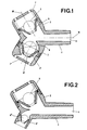
- the device does not provide during inspiration the percussion effect of the device of the FIG. 1, but only a valve effect allowing, in particular, the taking of a medicament.
- the lower ball 6 "of the apparatus shown in FIG. 2 is of smaller dimension than that of the upper ball 6. It is understood it is also possible to make the same type of device with a light lower ball, but larger than that of the upper ball.
- the support cone of the lower ball 6 is preferably arranged so that its axis is inclined, so that the ball does not lift, but remains in contact with the cone.
- the ball lifts and tends to make movements describing convolutions along the walls of the cones, which slows down the closing movement.
- the axis of the cone is inclined so that the ball remains in contact with the cone and as the cone constitutes a raceway for the ball, the closing movement is faster.
- the part 3 'inclined downward can be replaced by a simple orifice 10 formed in the lower part of the first straight tubular part 1, near the bent part .
- a device 9 allowing the taking of a drug during an inspiration is mounted on the device at the location of this orifice, for example by screwing.
- this device comprises an inspiration valve, fixed to the device by means of a vent connector 14.
- the valve is designed to be closed in the rest state or during an expiration, but to open during an inspiration.
- the valve comprises a ball 11 which rests in the resting state on the conical edge 12 of an opening 13 of the medication-taking device.
- any other suitable form of valve could be provided.
- the device shown schematically in Figures 4 and 5 includes the traditional elements already described for pulmonary ventilation percussion during the patient's expiration.
- the rectilinear tubular part 21 which constitutes the end piece of the apparatus is extended at its other end, after the part 22 inclined upwards, by a portion of rectilinear tubular element 23 whose axis is parallel to that of the mouthpiece.
- This portion may include a valve 24 at its end, for example in the form of a flexible rubber disc fixed in its center 25 at the end of a slightly conical tube-shaped element 26.
- the element 26 is mounted, for example by clipping, at the front end of the portion of tubular element 23.
- the conical shape of the element 26 makes it possible to fix a pipe connected to a compressor aerosol or to a metering spray, by introducing simply the end of the pipe around part 26 and forcing.
- the same assembly can be carried out on the valve element of FIGS. 2 and 3.
- the device can include a level 27 making it possible to control its inclination.
- a chamber of the "spacer" type can be inserted between the apparatus and the tube so as to create a reserve of product to be inhaled.
- FIG. 6 illustrates a double-acting device combined with a metered dose inhaler 30 mounted at the top of the tip part 1, the metered dose inhaler being arranged so that a pressure on its base 31 injects a dose 32 of medication inside the tip 4.
- the apparatus shown in FIG. 7 is a double-acting apparatus making it possible to obtain the same effects as the apparatus represented in FIG. 1.
- a first straight tubular part 1 a second inclined part 2 upwards and a third part 3 inclined downwards.
- the third part is offset forward relative to the second part and mounted in a removable manner, for example by simple conical fitting, at the end of the first part, so as to constitute a modular device.
- This modular design facilitates on the one hand the dismantling of the device for cleaning and on the other hand allows the device to be easily modified to obtain, for example, one of the configuration shown in FIGS. 8 and 9.
- the third part comprises a space 70 enlarged relative to that of the apparatus of FIG. 7, so as to constitute, for example, a nebulization chamber 71, provided with an orifice 72 allowing its connection to a compressor.
- the nebulizer 73 can be housed inside the chamber 71.
- the third part of the apparatus comprises a chamber 74, on which a spray-metering device 75 is mounted, said chamber 74 constituting what is called in the dedicated language a " spacer ", intended to provide the patient with a larger and more homogeneous volume of particles and to create a reserve of product to be inhaled, allowing better absorption of the particles by the patient.
- the ball 6 'of any of the devices shown in Figures 7 to 9 can be a light ball, which then has no other function than that of a valve.
- the device shown in FIG. 10 is a variant of the device in FIG. 4. It comprises a tubular element 81, 81 ′ in the shape of a T provided with an element 82 of resistance to expiration, and comprising a nozzle. buccal 83 at one of its lateral ends and a valve 84 at its opposite end.
- the element 82 has been shown in the same plane as the T-shaped tubular element. In reality, the tubular element 81 is found to be perpendicular to the plane of the drawing.
- the cone element 5 In order to allow the therapist to refine his treatment according to the parameters of the patient to be treated, the cone element 5, if it is a device with single effect at expiration, and / or the element of cone 5 ', in the case of a double-acting device, can be shaped so that the generator of the cone has a shape (as shown for example in one of FIGS. 12a to 12d) determined according to of a particular channel opening cycle.
- each of the devices described above can be produced with an air exhaust channel, and / or if necessary, with an air inspiration channel , comprising a removable cone element, a set of interchangeable cone elements being provided, each of said cone elements having a shape arranged to correspond to a particular cycle of opening / closing of the channel (FIG. 11).
- the first group relates to cone elements 40 having a generator of concave shape (FIG. 12a).
- a form makes it possible to reduce the overpressure phase (interruption time TI), to increase the opening time, as well as the frequency of the oscillations and possibly the total opening time and to decrease the acceleration of the flow.
- the second group relates to cone elements 41 having a generator of convex shape (FIG. 12b).
- a form makes it possible to increase the overpressure phase (increase in the TI time), to decrease the opening time, as well as the frequency of the oscillations, while increasing the total opening time and the acceleration of the flow.
- the third group relates to cone elements 42, the generatrix of which comprises a lower part of convex shape and an upper part of concave shape (FIG. 12c).
- the fourth group comprises cone elements 43, the generator of which comprises a lower part of concave shape and an upper part of convex shape (FIG. 12d).
Abstract
Description
La présente invention a pour objet un appareil thérapeutique spécifique du domaine respiratoire.The present invention relates to a therapeutic device specific to the respiratory field.
Un appareil de résistance à l'expiration destiné à améliorer la ventilation pulmonaire est décrit dans le brevet européen no 0337990. Cet appareil est de petites dimensions, simple et peu coûteux. Il peut être facilement transporté, par exemple dans une poche, et permet d'obtenir des résultats équivalents à ceux obtenus avec les appareils de conception plus complexe, qui sont en général fort encombrants et fort coûteux. Il comprend une première partie de forme tubulaire comportant un orifice d'entrée d'air dans lequel le patient doit expirer et une seconde partie comportant un canal d'échappement de forme conique circulaire, dans lequel est disposée une bille sphérique de diamètre supérieur aux dimensions de l'orifice d'entrée du canal, de façon à obstruer le canal avant expiration. L'axe du canal conique est incliné vers le haut par rapport à l'axe de la partie de forme tubulaire d'un angle qui peut être compris entre 30° et 80°. L'angle formé par une génératrice de la paroi de ce canal et son axe est inférieur à l'angle d'inclinaison de l'axe du canal. L'appareil comprend en outre un ou plusieurs trous situés dans une zone opposée à l'orifice d'entrée du canal conique pour permettre à l'air expiré de s'échapper, les dimensions du trou étant choisies de façon à empêcher l'échappement de la bille. La bille peut ainsi se déplacer librement dans le canal en opposant une résistance à l'expiration de l'air expiré par le patient, la partie la plus basse du canal constituant un lit de roulement pour la bille, tandis que la partie la plus haute du canal constitue une butée au mouvement de la bille. Avant l'expiration, la bille obstrue le canal du cône. Durant l'expiration, sa position instantanée résulte d'un état d'équilibre entre la pression de l'air expiré et la force de gravité de la bille combinée avec la pente de son lit de roulement. Ainsi, pendant l'expiration, du fait de sa caractéristique d'amortissement très faible, la bille effectue un mouvement oscillatoire engendrant une pression variable qui s'oppose à l'expiration, en constituant une résistance oscillante positive à l'expiration.An exhalation resistance device intended to improve pulmonary ventilation is described in European Patent No. 0337990. This device is small, simple and inexpensive. It can be easily transported, for example in a pocket, and makes it possible to obtain results equivalent to those obtained with devices of more complex design, which are generally very bulky and very expensive. It comprises a first part of tubular shape comprising an air inlet orifice in which the patient must breathe out and a second part comprising an exhaust channel of circular conical shape, in which is arranged a spherical ball of diameter greater than the dimensions from the inlet of the canal, so as to obstruct the canal before expiration. The axis of the conical channel is inclined upward relative to the axis of the tubular part of an angle which can be between 30 ° and 80 °. The angle formed by a generatrix of the wall of this channel and its axis is less than the angle of inclination of the axis of the channel. The apparatus further includes one or more holes located in an area opposite the inlet of the conical channel to allow expired air to escape, the dimensions of the hole being chosen so as to prevent escape. of the ball. The ball can thus move freely in the channel by opposing a resistance to the expiration of the air exhaled by the patient, the lowest part of the channel constituting a rolling bed for the ball, while the highest part of the channel constitutes a stop to the movement of the ball. Before expiration, the ball obstructs the cone channel. During expiration, its instantaneous position results from a state of equilibrium between the pressure of the exhaled air and the force of gravity of the ball combined with the slope of its tread. Thus, during expiration, due to its very weak damping characteristic, the ball performs an oscillatory movement generating a variable pressure which opposes expiration, constituting a positive oscillating resistance at expiration.
L'expérience a montré que cet l'appareil permet une ventilation en percussion d'une grande efficacité, des sécrétions étant mobilisées en quelques minutes dans l'arbre bronchique du patient, permettant leur expectoration aisée. Des mesures par ballonnets oesophagiens ont montré que le phénomène de percussion atteint le niveau périphérique du poumon. Les études cliniques entreprises ont permis de mettre en évidence, une résistance oscillante à l'expiration COS (Controlled Oscillating System) de valeur toujours positive, adaptée aux valeurs thérapeutiques connues. Ces études ont également montré que le système COS permet une régulation automatique de la pression et une adaptation de la fréquence de l'oscillation, ces deux caractéristiques étant inhérentes au système et non dépendantes du débit d'air.Experience has shown that this device allows percussion ventilation of great efficiency, secretions being mobilized in a few minutes in the patient's bronchial tree, allowing their easy expectoration. Measurements with esophageal balloons have shown that the phenomenon of percussion reaches the peripheral level of the lung. The clinical studies undertaken have made it possible to demonstrate an oscillating resistance to expiration COS (Controlled Oscillating System) of always positive value, adapted to known therapeutic values. These studies have also shown that the COS system allows automatic pressure regulation and adaptation of the oscillation frequency, these two characteristics being inherent in the system and not dependent on the air flow.
La synthèse des études cliniques mentionnées ci-dessus, complétée par des observations expérimentales très rigoureuses ont permis d'établir la courbe du cycle d'ouverture/fermeture de l'appareil décrit ci-dessus.The synthesis of the clinical studies mentioned above, supplemented by very rigorous experimental observations made it possible to establish the curve of the opening / closing cycle of the device described above.
Cette courbe représentée à la figure 11 met en évidence le principe de fonctionnement de l'appareil. Après une surpression, la bille qui obstrue le canal se déplace et laisse l'air s'échapper par un orifice, croissant en fonction de sa position (la vitesse du flux moyen expiratoire n'est pratiquement pas réduite). Puis la pression chute et la bille revient à sa position initiale d'obstruction de l'orifice du cône, créant à nouveau une surpression déterminée, qui constitue le départ d'un nouveau cycle.This curve shown in Figure 11 highlights the principle of operation of the device. After an overpressure, the ball which obstructs the channel moves and lets the air escape through an orifice, increasing according to its position (the speed of the average expiratory flow is practically not reduced). Then the pressure drops and the ball returns to its initial position of obstruction of the orifice of the cone, again creating a determined overpressure, which constitutes the start of a new cycle.
Un cycle d'ouverture/fermeture se compose donc d'un temps total d'ouverture TTO (= temps d'ouverture TO + temps d'ouverture totale TOT + temps de fermeture TF) et d'un temps d'interruption TI.An opening / closing cycle therefore consists of a total opening time TTO (= opening time TO + total opening time TOT + closing time TF) and an interruption time TI.
C'est pendant le temps d'interruption TI qu'est générée la surpression. Les phases d'accélération TO et d'ouverture totale TOT permettent de maintenir une très grande vitesse du flux d'air, ce qui, en plus de l'effet thérapeutique recherché, facilite grandement l'utilisation de l'appareil.It is during the TI interruption time that the overpressure is generated. The acceleration phases TO and total opening TOT make it possible to maintain a very high speed of the air flow, which, in addition to the desired therapeutic effect, greatly facilitates the use of the device.
Durant le cycle expiratoire, la bille subit donc un mouvement oscillatoire. La fréquence des oscillations, c'est-à-dire le nombre de cycles d'ouvertu- re/fermeture par unité de temps, peut être modulée par l'inclinaison de l'appareil de quelques degrés en-dessus ou en-dessous de l'horizontale.During the expiratory cycle, the ball therefore undergoes an oscillatory movement. The frequency of the oscillations, i.e. the number of opening / closing cycles per unit of time, can be modulated by tilting the device a few degrees above or below the horizontal.
On s'est également aperçu que lorsque cet appareil de résistance à l'expiration est utilisé par un patient immédiatement après l'inhalation d'un médicament, le flux d'air turbulent provoqué dans les poumons lors de l'expiration dans l'appareil permet d'une part aux particules de médicament de pénétrer plus loin dans l'arbre bronchique et d'autre part d'améliorer la déposition de ces particules dans les poumons.It has also been found that when this expiration resistance device is used by a patient immediately after inhaling a drug, the turbulent air flow caused in the lungs upon expiration in the device on the one hand allows drug particles to penetrate further into the bronchial tree and on the other hand to improve the deposition of these particles in the lungs.
Le but de la présente invention est de mettre à profit les observations qui précèdent et de proposer un appareil spécifique du domaine respiratoire conçu selon le principe de base de l'appareil décrit ci-dessus, mais offrant des possibiltés thérapeutiques améliorées et/ou plus larges.The purpose of the present invention is to take advantage of the above observations and to propose a device specific to the respiratory domain designed according to the basic principle of the device described above, but offering improved and / or broader therapeutic possibilities. .
A cet effet, la présente invention concerne un appareil thérapeutique spécifique du domaine respiratoire, tel que défini à la revendication 1.To this end, the present invention relates to a therapeutic device specific to the respiratory field, as defined in
Un tel appareil permet d'obtenir un effet thérapeutique tant à l'expiration qu'à l'inspiration.Such an apparatus makes it possible to obtain a therapeutic effect both at expiration and at inspiration.
Selon un mode de réalisation, l'appareil permet d'obtenir une ventilation en percussion ayant les effets décrits plus haut, tant à l'expiration qu'à l'inspiration.According to one embodiment, the device makes it possible to obtain percussion ventilation having the effects described above, both on expiration and on inspiration.
Selon un autre mode d'exécution, l'appareil est agencé pour permettre non seulement une ventilation pulmonaire en percussion, mais également pourfavo- riser la prise de médicaments.According to another embodiment, the device is arranged to allow not only percussion pulmonary ventilation, but also to favor the taking of drugs.
L'invention concerne également un élément de canal conique pour l'appareil thérapeutique spécifique du domaine respiratoire selon le préambule de la revendication 11, tel que défini dans la partie carac- térisante de la revendication 11, ainsi qu'un appareil thérapeutique spécifique du domaine respiratoire comportant un tel élément de canal conique, tel que spécifié à la revendication 16.The invention also relates to a conical channel element for the specific therapeutic apparatus of the respiratory domain according to the preamble of
Selon un mode d'exécution, l'appareil est agencé pour obtenir un effet thérapeutique à l'expiration et/ou à l'inspiration et est doté d'un ensemble d'éléments coniques interchangeables, la forme de chacun des éléments de cônes étant agencée de façon à permettre une adaptation du cycle d'ouverture/fer- meture à différents modes thérapeutiques spécifiques.According to one embodiment, the apparatus is arranged to obtain a therapeutic effect on expiration and / or inspiration and is provided with a set of interchangeable conical elements, the shape of each of the cone elements being arranged to allow adaptation of the opening / closing cycle to different specific therapeutic modes.
Cette interchangeabilité permet au thérapeute d'adapter très précisément le fonctionnement de l'appareil aux caractéristiques précises de la thérapie qu'il souhaite faire adopter par le patient, en jouant sur les rapports entre les temps d'interruption TI (phase de surpression), d'ouverture TO (phase d'accélération du flux), d'ouverture totale TOT (échappement libre) et de fermeture TF.This interchangeability allows the therapist to very precisely adapt the functioning of the device to the precise characteristics of the therapy that he wishes the patient to adopt, by playing on the relationships between the TI interruption times (overpressure phase), opening TO (flow acceleration phase), total opening TOT (free exhaust) and closing TF.
La description qui suit, donnée à titre d'exemple, se réfère aux dessins annexés sur lesquels:
- la figure 1 est une coupe verticale schématique d'un exemple d'appareil selon l'invention à double effet, tant à l'expiration qu'à l'inspiration;
- la figure 2 est une coupe verticale schématique d'un exemple d'appareil selon l'invention muni d'une soupape d'inspiration, notamment pour la prise d'un médicament;
- la figure 3 est une coupe verticale d'un détail d'une variante de soupape d'inspiration;
- la figure 4 est une coupe verticale schématique d'un exemple d'appareil selon l'invention pouvant être connecté tant à un aérosol qu'à un spray-doseur;
- la figure 5 est une vue depuis l'avant de l'appareil de la figure 4;
- la figure 6 est une coupe verticale schématique d'un autre exemple d'appareil à double effet, combiné avec un aérosol-doseur;
- la figure 7 est une coupe verticale schématique d'un autre exemple d'appareil à double effet,
- la figure 8 est une coupe verticale schématique d'un exemple d'appareil comportant une chambre de nébulisation,
- la figure 9 est une coupe verticale schématique d'un autre exemple d'appareil muni d'un spray-doseur,
- la figure 10 est une coupe verticale schématique d'une variante de l'appareil de la figure 4,
- la figure 11 est un diagramme illustrant le principe du cycle d'ouverture/fermeture d'un appareil de résistance à l'expiration, tel que celui décrit dans le brevet européen no 0337990; et
- les figures 12a à 12d illustrent différentes formes d'éléments de cônes permettant une adaptation du cycle d'ouverture/fermeture à différents modes thérapeutiques spécifiques.
- Figure 1 is a schematic vertical section of an example of apparatus according to the invention with double effect, both at expiration and at inspiration;
- Figure 2 is a schematic vertical section of an example of an apparatus according to the invention provided with an inspiration valve, in particular for taking a drug;
- Figure 3 is a vertical section through a detail of an alternative inspiration valve;
- FIG. 4 is a schematic vertical section of an example of an apparatus according to the invention which can be connected both to an aerosol and to a metered spray;
- Figure 5 is a view from the front of the apparatus of Figure 4;
- Figure 6 is a schematic vertical section of another example of a double-acting device, combined with a metered dose inhaler;
- FIG. 7 is a schematic vertical section of another example of a double-acting device,
- FIG. 8 is a schematic vertical section of an example of an apparatus comprising a nebulization chamber,
- FIG. 9 is a schematic vertical section of another example of an apparatus provided with a metering spray,
- FIG. 10 is a schematic vertical section of a variant of the device of FIG. 4,
- FIG. 11 is a diagram illustrating the principle of the opening / closing cycle of an expiration resistance device, such as that described in European patent No. 0337990; and
- Figures 12a to 12d illustrate different shapes of cone elements allowing adaptation of the opening / closing cycle to different specific therapeutic modes.
L'appareil représenté à la figure 1 est un appareil à double effet permettant d'obtenir une ventilation pulmonaire en percussion tant à l'expiration qu'à l'inspiration. Il comprend un élément en forme de double pipe, comportant une première partie 1 tubulaire rectiligne, une deuxième partie 2 inclinée vers le haut par rapport à la première partie et une troisième partie 3 inclinée vers le bas par rapport à la première partie. La première partie tubulaire comporte un orifice 4 d'entrée d'air dans lequel le patient peut soit expirer, soit inspirer. Chacune des deuxième et troisième parties comporte un élément 5, respectivement 5', en forme de cône tronqué et une bille 6, respectivement 6', dont le diamètre est supérieur au plus petit diamètre de l'élément conique correspondant. Le cône 5 de la partie inclinée vers le haut est disposé de façon que son orifice de plus grand diamètre soit situé vers le haut, et que la bille s'appuie à l'intérieur du cône sur les parois de celui-ci, les caractéristiques de cette partie de l'appareil étant celles de l'appareil décrit dans le brevet européen no 0337990 mentionné plus haut. De même, le cône 5' disposé dans la partie inclinée vers le bas est tourné de façon que son orifice de plus grand diamètre soit également situé vers le haut, c'est-à -dire dans ce cas vers l'intérieur de l'appareil, afin, qu'à l'état de repos, la seconde bille s'appuie sur les parois internes du cône et obstrue le canal. L'appareil comporte en outre deux couvercles 7, 7' disposés respectivement à l'extrémité de chacune des parties 2, 3 inclinées vers le haut et vers le bas, lesdits couvercles étant troués de façon à permettre d'une part à l'airexpiré de s'échapper travers le premier couvercle 7 et d'autre part à l'air inspiré de s'introduire à travers le second couvercle 7'. Il résulte de l'agencement décrit ci-dessus que, lors d'une expiration, l'orifice constitué par la partie inclinée vers le bas est fermé par le blocage de la seconde bille 6' dans le cône inférieur 5' sous l'effet de la pression de l'air, alors que l'air s'échappe par la partie inclinée vers le haut, la première bille 6 se déplaçant sous l'effet de l'expiration et procurant l'effet de ventilation en percussion déjà décrit plus haut. Lors d'une inspiration l'orifice constitué par la partie inclinée vers le haut est obstrué par la première bille 6 sous l'effet de son poids propre, alors que la bille 6' disposée dans le cône inférieur se soulève de façon à permettre le passage de l'air, d'où il résulte une ventilation en percussion du même type que celle qui intervient lors de l'expiration. Les couvercles 7, 7', ainsi que les cônes 5, 5' sont amovibles, de façon à permettre, notamment, un nettoyage efficace de l'appareil.The device represented in FIG. 1 is a double-effect device making it possible to obtain pulmonary ventilation by percussion both on expiration and on inspiration. It comprises an element in the form of a double pipe, comprising a first tubular
Le cône 5' de la partie inclinée vers le bas peut être incliné dans le même sens que le cône supérieur, de façon que son axe soit sensiblement parallèle à celui du cône supérieur, comme représenté en traitillé sur la figure 1. Il peut également être incliné dans le sens opposé au cône supérieur, comme représenté en trait plein sur la figure 1. Les angles d'inclinaison des cônes seront choisis de façon à éviter que les billes ne se soulèvent et flottent au-dessus de leur support, mais qu'elles restent en contact avec celui-ci, de façon à obtenir le meilleur effet de percussion souhaité. Selon le mode d'exécution représenté à la figure 1, le cône inférieur est monté en pivotement à l'intérieur d'un élément de sphère 8, ce qui permet de faire varier l'inclinaison du cône, en agissant par exemple sur un organe d'actionnement, tel qu'un axe (non-représenté) faisant saillie à l'extérieur de l'appareil.The
La partie 2 inclinée vers le haut et la partie 3 inclinée vers le bas de l'appareil à double effet représenté à la figure 1 sont sensiblement de mêmes dimensions. On remarquera toutefois qu'une telle similitude de dimensions n'est nullement nécessaire et que la partie inclinée vers le bas peut être réalisée avec des dimensions inférieures (ou respectivement supérieures) à celles de la partie inclinée vers le haut et donc avec un cône et une bille de dimension inférieure (ou respectivement supérieure) à celle du cône et de la bille de la partie supérieure, selon la ou les fonction(s) assignée(s) à l'appareil et/ou l'effet thérapeutique recherché.
Il est d'autre part possible de réaliser l'appareil, comme représenté à la figure 2, avec une bille inférieure 6" légère, l'appareil ne procurant pas lors d'une inspiration l'effet de percussion de l'appareil de la figure 1, mais seulement un effet de valve permettant, notamment, la prise d'un médicament. La bille inférieure 6" de l'appareil représenté à la figure 2 est de dimension inférieure à celle de la bille supérieure 6. Il est bien entendu également possible de réaliser le même type d'appareil avec une bille inférieure légère, mais de dimension supérieure à celle de la bille supérieure. Dans les deux cas, on disposera de préférence le cône de support de la bille inférieure 6" de façon que son axe soit incliné, afin que la bille ne se soulève pas, mais reste en contact avec le cône. En effet, si l'axe du cône est vertical, la bille se soulève et a tendance à effectuer des mouvements décrivant des circonvolutions le long des parois du cônes, ce qui freine le mouvement de fermeture. Par contre, lorsque l'axe du cône est incliné de façon que la bille reste en contact avec le cône et que le cône constitue un chemin de roulement pour la bille, le mouvement de fermeture est plus rapide.It is also possible to make the device, as shown in Figure 2, with a
Selon une variante d'exécution de l'appareil de la figure 2, la partie 3' inclinée vers le bas peut être remplacée par un simple orifice 10 pratiqué dans la partie inférieure de la première partie tubulaire rectiligne 1, à proximité de la partie coudée. Un dispositif 9 permettant la prise d'un médicament lors d'une inspiration est monté sur l'appareil à l'endroit de cet orifice, par exemple par vissage. Comme représenté à la figure 3, ce dispositif comporte une valve d'inspiration, fixée sur l'appareil par l'intermédiaire d'un raccord à évent 14. La valve est agencée pour être fermée à l'état de repos ou lors d'une expiration, mais pour s'ouvrir lors d'une inspiration. La valve comporte une bille 11 qui repose à l'état de repos sur le bord conique 12 d'une ouverture 13 du dispositif de prise de médicaments. Bien entendu, toute autre forme adéquate de valve pourrait être prévue.According to an alternative embodiment of the device of Figure 2, the part 3 'inclined downward can be replaced by a
L'appareil représenté schématiquement aux figures 4 et 5 comporte les éléments traditionnels déjà décrits permettant la ventilation pulmonaire en percussion lors d'une expiration du patient. La partie tubulaire rectiligne 21 qui constitue l'embout de l'appareil est prolongée à son autre extrémité, après la partie 22 inclinée vers le haut, par une portion d'élément tubulaire rectiligne 23 dont l'axe est parallèle à celui de l'embout. Cette portion peut comporter une valve 24 à son extrémité, par exemple sous forme d'un disque de caoutchouc souple fixé en son centre 25 à l'extrémité d'un élément en forme de tube légèrement conique 26. L'élément 26 est monté, par exemple par clip- sage, à l'extrémité avant de la portion d'élément tubulaire 23. La forme conique de l'élément 26 permet d'y fixer un tuyau relié à un aérosol compresseur ou à un spray-doseur, en introduisant simplement l'extrémité du tuyau autour de la partie 26 et en forçant. Le même montage peut être réalisé sur l'élément à soupape des figures 2 et 3. L'appareil peut comporter un niveau 27 permettant de contrôler son inclinaison. En outre, une chambre du type "spacer" peut être insérée entre l'appareil et le tuyau de façon à créer une réserve de produit à inhaler.The device shown schematically in Figures 4 and 5 includes the traditional elements already described for pulmonary ventilation percussion during the patient's expiration. The rectilinear
La figure 6 illustre un appareil à double effet combiné avec un aérosol-doseur 30 monté à la partie supérieure de la partie d'embout 1, l'aérosol-doseur étant agencé de façon qu'une pression sur sa base 31 injecte une dose 32 de médicament à l'intérieur de l'embout 4.FIG. 6 illustrates a double-acting device combined with a
L'appareil représenté à la figure 7 est un appareil à double effet permettant d'obtenir les mêmes effets que l'appareil représenté à la figure 1. On retrouve comme à la figure 1 une première partie 1 tubulaire rectiligne, une deuxième partie 2 inclinée vers le haut et une troisième partie 3 inclinée vers le bas. Toutefois la troisième partie est décalée vers l'avant par rapport à la deuxième partie et montée de façon amovible, par exemple par simple emboîtement conique, à l'extrémité de la première partie, de façon à constituer un appareil modulaire. Cette conception modulaire facilite d'une part le démontage de l'appareil pour son nettoyage et permet d'autre part de modifier facilement l'appareil pour l'obtention par exemple d'une des configuration représentées sur les figures 8 et 9.The apparatus shown in FIG. 7 is a double-acting apparatus making it possible to obtain the same effects as the apparatus represented in FIG. 1. As in FIG. 1, there is a first straight
Ainsi, selon la configuration de l'appareil représenté à la figure 8, la troisième partie comprend un espace 70 agrandi par rapport à celui de l'appareil de la figure 7, de façon à constituer, par exemple, une chambre de nébulisation 71, munie d'un orifice 72 permettant sa connexion à un compresseur. Comme représenté à la figure 8, le nébulisateur 73 peut être logé à l'intérieur de la chambre 71.Thus, according to the configuration of the apparatus represented in FIG. 8, the third part comprises a
De même, selon la configuration représentée à la figure 9, la troisième partie de l'appareil comprend une chambre 74, sur laquelle est monté un spray-doseur 75, ladite chambre 74 constituant ce que l'on appelle dans le langage consacré un "spacer", destiné à mettre à disposition du patient un volume de particules plus important et plus homogène et à créer une réserve de produit à inhaler, permettant une meilleure prise des particules par le patient.Likewise, according to the configuration shown in FIG. 9, the third part of the apparatus comprises a
Bien entendu, la bille 6' de l'un quelconque des appareils représentés aux figures 7 à 9 peut être une bille légère, qui n'a alors plus d'autre fonction que celle d'une valve.Of course, the ball 6 'of any of the devices shown in Figures 7 to 9 can be a light ball, which then has no other function than that of a valve.
On notera encore qu'il est possible de remplacer l'embout buccal de chacun des appareils décrits ci-dessus par un dispositif de connexion permettant l'intégration de l'appareil dans un système d'assistance respiratoire.It will also be noted that it is possible to replace the mouthpiece of each of the devices described above with a connection device allowing the integration of the device into a respiratory assistance system.
L'appareil représenté à la figure 10 est une variante de l'appareil de la figure 4. Il comporte un élément tubulaire 81, 81' en forme de T muni d'un élément 82 de résistance à l'expiration, et comportant un embout buccal 83 à l'une des ses extrémités latérales et une soupape 84 à son extrémité opposée. Pourdes raisons de représentation, on a représenté l'élément 82 dans le même plan que l'élément tubulaire en forme de T. En réalité, l'élément tubulaire 81 se trouve être perpendiculaire au plan du dessin.The device shown in FIG. 10 is a variant of the device in FIG. 4. It comprises a
Afin de permettre au thérapeute d'affiner son traitement en fonction des paramètres du patient à traiter, l'élément de cône 5, s'il s'agit d'un appareil à simple effet à l'expiration, et/ou l'élément de cône 5', lorsqu'il s'agit d'un appareil à double effet, peuvent être conformés de façon que la génératrice du cône ait une forme (comme représenté par exemple sur l'une des figures 12a à 12d) déterminée en fonction d'un cycle particulier d'ouverture du canal. De même, afin de faire évoluer le traitement pour un patient donné, chacun des appareils décrits ci-dessus peut être réalisé avec un canal d'échappement d'air, et/ou le cas échéant, avec un canal d'inspiration d'air, comportant un élément de cône amovible, un ensemble d'éléments de cône interchangeables étant prévu, chacun desdits éléments de cône ayant une forme agencée pour correspondre à un cycle particulier d'ouverture/fermeture du canal (figure 11).In order to allow the therapist to refine his treatment according to the parameters of the patient to be treated, the
Différentes formes de cônes peuvent être prévues selon l'effet souhaité. Les diverses formes intéressantes peuvent être regroupées en quatre groupes, que l'on a représenté sur les figures 12a à 12d.Different shapes of cones can be provided depending on the desired effect. The various interesting shapes can be grouped into four groups, which have been represented in FIGS. 12a to 12d.
Le premier groupe concerne des éléments de cône 40 ayant une génératrice de forme concave (figure 12a). Une telle forme permet de diminuer la phase de surpression (temps d'interruption TI), d'augmenter le temps d'ouverture, ainsi que la fréquence des oscillations et éventuellement le temps d'ouverture totale et de diminuer l'accélération du flux.The first group relates to
Le deuxième groupe concerne des éléments de cône 41 ayant une génératrice de forme convexe (figure 12b). Une telle forme permet d'augmenter la phase de surpression (augmentation du temps TI), de diminuer le temps d'ouverture, ainsi que la fréquence des oscillations, tout en augmentant le temps d'ouverture totale et l'accélération du flux.The second group relates to
Le troisième groupe concerne des éléments de cône 42 dont la génératrice comprend une partie inférieure de forme convexe et une partie supérieure de forme concave (figure 12c).The third group relates to
Le quatrième groupe comprend des éléments de cône 43 dont la génératrice comprend une partie inférieure de forme concave et une partie supérieure de forme convexe (figure 12d).The fourth group comprises
D'autres formes ou combinaisons de formes peuvent bien entendu être envisagées.Other shapes or combinations of shapes can of course be envisaged.
Claims (18)
Priority Applications (1)
| Application Number | Priority Date | Filing Date | Title |
|---|---|---|---|
| DE19939320493 DE9320493U1 (en) | 1992-04-10 | 1993-04-06 | Therapy device for specific use in the breathing area |
Applications Claiming Priority (2)
| Application Number | Priority Date | Filing Date | Title |
|---|---|---|---|
| CH1186/92 | 1992-04-10 | ||
| CH1186/92A CH685475A5 (en) | 1992-04-10 | 1992-04-10 | specific therapeutic device in the respiratory field. |
Publications (2)
| Publication Number | Publication Date |
|---|---|
| EP0565489A1 true EP0565489A1 (en) | 1993-10-13 |
| EP0565489B1 EP0565489B1 (en) | 1996-10-30 |
Family
ID=4204521
Family Applications (1)
| Application Number | Title | Priority Date | Filing Date |
|---|---|---|---|
| EP93810248A Expired - Lifetime EP0565489B1 (en) | 1992-04-10 | 1993-04-06 | Therapeutic apparatus for specific use in the respiratory field |
Country Status (7)
| Country | Link |
|---|---|
| US (1) | US5451190A (en) |
| EP (1) | EP0565489B1 (en) |
| AT (1) | ATE144717T1 (en) |
| CA (1) | CA2093759A1 (en) |
| CH (1) | CH685475A5 (en) |
| DE (1) | DE69305677T2 (en) |
| ES (1) | ES2092797T3 (en) |
Cited By (1)
| Publication number | Priority date | Publication date | Assignee | Title |
|---|---|---|---|---|
| WO1995005208A1 (en) * | 1993-08-18 | 1995-02-23 | Fisons Plc | Inhalator with breath flow regulation |
Families Citing this family (68)
| Publication number | Priority date | Publication date | Assignee | Title |
|---|---|---|---|---|
| WO1998004309A2 (en) * | 1996-07-27 | 1998-02-05 | Zygmunt Podolec | Device for controlled administration of medicines |
| US5829429A (en) * | 1997-04-21 | 1998-11-03 | Hughes; Arthur R. | Acoustic respiratory therapy apparatus |
| US6058932A (en) | 1997-04-21 | 2000-05-09 | Hughes; Arthur R. | Acoustic transceiver respiratory therapy apparatus |
| AU1242600A (en) * | 1998-11-06 | 2000-05-29 | Salter Labs | Nebulizer mouthpiece and accessories |
| EP1191977A1 (en) * | 1999-06-18 | 2002-04-03 | Powerlung Inc | Pulmonary exercise device |
| KR20010017069A (en) * | 1999-08-06 | 2001-03-05 | 정진구 | Pulmonary respiration intensifying instrument |
| US6581598B1 (en) * | 1999-11-24 | 2003-06-24 | Dhd Healthcare Corporation | Positive expiratory pressure device |
| US6776159B2 (en) | 1999-11-24 | 2004-08-17 | Dhd Healthcare Corporation | Positive expiratory pressure device with bypass |
| US7059324B2 (en) * | 1999-11-24 | 2006-06-13 | Smiths Medical Asd, Inc. | Positive expiratory pressure device with bypass |
| US6568387B2 (en) | 2000-07-19 | 2003-05-27 | University Of Florida | Method for treating chronic obstructive pulmonary disorder |
| US6539938B2 (en) | 2000-12-15 | 2003-04-01 | Dhd Healthcare Corporation | Maximum expiratory pressure device |
| US6718969B1 (en) * | 2002-05-28 | 2004-04-13 | Darren Rubin | Medication dosage inhaler system |
| US7416536B2 (en) * | 2002-10-02 | 2008-08-26 | Devlieger Marten Jan | Chest vibrating device |
| US6792942B1 (en) * | 2003-05-30 | 2004-09-21 | Jung-Hua Ho | Sleep silencer |
| AU2006287934B2 (en) * | 2005-05-18 | 2012-12-13 | Nektar Therapeutics | Valves, devices, and methods for endobronchial therapy |
| EP1772165A1 (en) * | 2005-10-08 | 2007-04-11 | Ulrich Cegla | Inhalation apparatus |
| US7617821B2 (en) | 2005-11-23 | 2009-11-17 | Vibralung, Inc. | Acoustic respiratory therapy apparatus |
| US7578294B2 (en) * | 2005-12-02 | 2009-08-25 | Allegiance Corporation | Nasal continuous positive airway pressure device and system |
| RU2306161C1 (en) * | 2006-01-24 | 2007-09-20 | Яков Абраммерович Гольдштейн | Breathing training device |
| US8460223B2 (en) | 2006-03-15 | 2013-06-11 | Hill-Rom Services Pte. Ltd. | High frequency chest wall oscillation system |
| US7909033B2 (en) | 2006-05-03 | 2011-03-22 | Comedica Incorporated | Breathing treatment apparatus |
| US8051854B2 (en) | 2006-09-15 | 2011-11-08 | Comedica Incorporated | Continuous high-frequency oscillation breathing treatment apparatus |
| US7779841B2 (en) * | 2006-11-13 | 2010-08-24 | Carefusion 2200, Inc. | Respiratory therapy device and method |
| US9050434B2 (en) | 2007-05-18 | 2015-06-09 | Comedica Incorporated | Lung therapy device |
| US8251876B2 (en) | 2008-04-22 | 2012-08-28 | Hill-Rom Services, Inc. | Breathing exercise apparatus |
| US8539951B1 (en) | 2008-05-27 | 2013-09-24 | Trudell Medical International | Oscillating positive respiratory pressure device |
| US8327849B2 (en) | 2008-10-28 | 2012-12-11 | Trudell Medical International | Oscillating positive expiratory pressure device |
| US8485179B1 (en) | 2009-02-23 | 2013-07-16 | Trudell Medical International | Oscillating positive expiratory pressure device |
| US9149589B2 (en) | 2009-02-23 | 2015-10-06 | Trudell Medical International | Method and device for performing orientation dependent oscillating positive expiratory pressure therapy |
| WO2010097119A1 (en) | 2009-02-27 | 2010-09-02 | Pari GmbH Spezialisten für effektive Inhalation | Method for operating an aerosol inhalation device and aerosol inhalation device |
| US9151425B2 (en) | 2009-11-02 | 2015-10-06 | Comedica Incorporated | Multiple conduit connector apparatus and method |
| US8177689B2 (en) | 2010-03-01 | 2012-05-15 | Bas Rutten | Oxygen trainer device |
| GB201006736D0 (en) * | 2010-04-22 | 2010-06-09 | Mian Omar | Gas flow indicator |
| EP2380618A1 (en) | 2010-04-26 | 2011-10-26 | PARI Pharma GmbH | Operating method for an aerosol delivery device and aerosol delivery device |
| JP5795637B2 (en) * | 2010-09-21 | 2015-10-14 | コーニンクレッカ フィリップス エヌ ヴェ | Vibratory positive expiratory pressure device |
| US8607794B2 (en) | 2010-10-05 | 2013-12-17 | Carefusion 207, Inc. | Non-invasive breathing assistance apparatus and method |
| US8567400B2 (en) | 2010-10-05 | 2013-10-29 | Carefusion 207, Inc. | Non-invasive breathing assistance device with flow director |
| US9358417B2 (en) | 2011-06-06 | 2016-06-07 | Trudell Medical International | Oscillating positive expiratory pressure device |
| US9180271B2 (en) | 2012-03-05 | 2015-11-10 | Hill-Rom Services Pte. Ltd. | Respiratory therapy device having standard and oscillatory PEP with nebulizer |
| US9549869B2 (en) | 2012-06-29 | 2017-01-24 | Hill-Rom Canado Respiratory Ltd. | Wearable thorax percussion device |
| US9744097B2 (en) | 2012-06-29 | 2017-08-29 | Hill-Rom Services Pte. Ltd. | Wearable thorax percussion device |
| US9517315B2 (en) | 2012-11-30 | 2016-12-13 | Trudell Medical International | Oscillating positive expiratory pressure device |
| US9795752B2 (en) | 2012-12-03 | 2017-10-24 | Mhs Care-Innovation, Llc | Combination respiratory therapy device, system, and method |
| EP2783728B1 (en) * | 2013-03-26 | 2016-12-14 | R. Cegla GmbH & Co. KG | Therapy device for the treatment of respiratory diseases |
| GB201310826D0 (en) | 2013-06-18 | 2013-07-31 | Smiths Medical Int Ltd | Respiratory therapy apparatus and methods |
| WO2015003249A1 (en) * | 2013-07-12 | 2015-01-15 | Trudell Medical International | Huff cough simulation device |
| US9849257B2 (en) | 2013-08-22 | 2017-12-26 | Trudell Medical International | Oscillating positive respiratory pressure device |
| US10363383B2 (en) | 2014-02-07 | 2019-07-30 | Trudell Medical International | Pressure indicator for an oscillating positive expiratory pressure device |
| US10004872B1 (en) | 2015-03-06 | 2018-06-26 | D R Burton Healthcare, Llc | Positive expiratory pressure device having an oscillating valve |
| EP3552649B1 (en) | 2015-04-02 | 2023-08-23 | Hill-Rom Services PTE. LTD. | Pressure control of respiratory device |
| CN104906678A (en) * | 2015-06-09 | 2015-09-16 | 广州医科大学附属第一医院 | Ball moving type isolation and exhaust valve |
| WO2017017657A1 (en) | 2015-07-30 | 2017-02-02 | Trudell Medical International | Combined respiratory muscle training and oscillating positive expiratory pressure device |
| USD780906S1 (en) | 2015-09-02 | 2017-03-07 | Trudell Medical International | Respiratory treatment device |
| USD778429S1 (en) | 2015-09-02 | 2017-02-07 | Trudell Medical International | Respiratory treatment device |
| RU2638277C2 (en) * | 2015-12-01 | 2017-12-12 | Геннадий Владимирович Сурнинов | Surninov's respiratory training device |
| US10857317B2 (en) | 2015-12-04 | 2020-12-08 | Trudell Medical International | Huff cough simulation device |
| US11471366B2 (en) | 2016-08-22 | 2022-10-18 | Hill-Rom Services Pte. Ltd. | Percussion therapy apparatus and methods thereof |
| US11213641B2 (en) * | 2016-09-14 | 2022-01-04 | Healthy Humming, LLC | Therapeutic device for treatment of conditions relating to the sinuses, nasal cavities, ear, nose and throat |
| US11432993B2 (en) * | 2016-09-14 | 2022-09-06 | Healthy Humming, LLC | Therapeutic device for treatment of conditions relating to the sinuses, nasal cavities, ear, nose and throat |
| WO2018053079A1 (en) * | 2016-09-14 | 2018-03-22 | Bogan Consulting Services, P.A. | Therapeutic device for treatment of conditions relating to the sinuses, nasal cavities, ear, nose and throat |
| US11305077B2 (en) * | 2016-09-14 | 2022-04-19 | Healthy Humming, LLC | Therapeutic device for treatment of conditions relating to the sinuses, nasal cavities, ear, nose and throat |
| WO2018203188A1 (en) | 2017-05-03 | 2018-11-08 | Trudell Medical International | Combined oscillating positive expiratory pressure therapy and huff cough simulation device |
| US11878125B2 (en) * | 2017-10-03 | 2024-01-23 | Yasi's, Llc | Respiratory therapy |
| US10953278B2 (en) | 2018-02-02 | 2021-03-23 | Trudell Medical International | Oscillating positive expiratory pressure device |
| US20210008411A1 (en) * | 2020-07-28 | 2021-01-14 | Likai Fu | Lung clearing and body building machine |
| EP3954418A1 (en) * | 2020-08-11 | 2022-02-16 | CEGLA Medizintechnik GmbH & Co. KG | Respiratory therapy apparatus |
| CN112619069B (en) * | 2020-12-16 | 2022-04-22 | 无锡市儿童医院 | Child breathes trainer |
| KR102357405B1 (en) * | 2021-05-07 | 2022-02-09 | 정진구 | Respiratory exercise equipment |
Citations (6)
| Publication number | Priority date | Publication date | Assignee | Title |
|---|---|---|---|---|
| US4062358A (en) * | 1976-04-21 | 1977-12-13 | Kritzer Richard W | Respirators |
| US4231375A (en) * | 1977-10-20 | 1980-11-04 | Boehringer John R | Pulmonary exerciser |
| US4739987A (en) * | 1985-10-28 | 1988-04-26 | Nicholson Marguerite K | Respiratory exerciser |
| EP0311770A2 (en) * | 1987-08-14 | 1989-04-19 | Udo Dr. Raupach | Device for respiration therapy |
| WO1989003707A1 (en) * | 1987-10-22 | 1989-05-05 | Claude Liardet | Expiration resistance apparatus for improving the pulmonary ventilation |
| EP0411714A1 (en) * | 1989-08-03 | 1991-02-06 | Emmanuel Labaere | Appliance for use in inspiration and expiration techniques |
Family Cites Families (11)
| Publication number | Priority date | Publication date | Assignee | Title |
|---|---|---|---|---|
| US3079A (en) * | 1843-05-08 | Breathing-tube | ||
| DE284810C (en) * | ||||
| CA804907A (en) * | 1969-01-28 | J. A. Lichtneckert Istvan | Breathing apparatus | |
| US2890697A (en) * | 1957-03-15 | 1959-06-16 | Wilton E Van Sickle | Enclosed medicament container and atomizer |
| US3900138A (en) * | 1972-08-07 | 1975-08-19 | Minnesota Mining & Mfg | Medicament dispenser |
| US3908987A (en) * | 1973-09-27 | 1975-09-30 | John R Boehringer | Controlled positive end pressure expiratory device |
| ZA811942B (en) * | 1980-03-25 | 1983-02-23 | H Malem | Nebulising apparatus |
| US5007419A (en) * | 1989-09-25 | 1991-04-16 | Allan Weinstein | Inhaler device |
| EP0493560A1 (en) * | 1990-07-27 | 1992-07-08 | Franco Del Bon | Inhalation device |
| US5178138A (en) * | 1990-09-11 | 1993-01-12 | Walstrom Dennis R | Drug delivery device |
| WO1993003782A1 (en) * | 1991-08-15 | 1993-03-04 | Bon F Del | Inhaler |
-
1992
- 1992-04-10 CH CH1186/92A patent/CH685475A5/en not_active IP Right Cessation
-
1993
- 1993-04-06 DE DE69305677T patent/DE69305677T2/en not_active Expired - Lifetime
- 1993-04-06 ES ES93810248T patent/ES2092797T3/en not_active Expired - Lifetime
- 1993-04-06 AT AT93810248T patent/ATE144717T1/en active
- 1993-04-06 EP EP93810248A patent/EP0565489B1/en not_active Expired - Lifetime
- 1993-04-08 CA CA002093759A patent/CA2093759A1/en not_active Abandoned
- 1993-04-09 US US08/045,974 patent/US5451190A/en not_active Expired - Lifetime
Patent Citations (6)
| Publication number | Priority date | Publication date | Assignee | Title |
|---|---|---|---|---|
| US4062358A (en) * | 1976-04-21 | 1977-12-13 | Kritzer Richard W | Respirators |
| US4231375A (en) * | 1977-10-20 | 1980-11-04 | Boehringer John R | Pulmonary exerciser |
| US4739987A (en) * | 1985-10-28 | 1988-04-26 | Nicholson Marguerite K | Respiratory exerciser |
| EP0311770A2 (en) * | 1987-08-14 | 1989-04-19 | Udo Dr. Raupach | Device for respiration therapy |
| WO1989003707A1 (en) * | 1987-10-22 | 1989-05-05 | Claude Liardet | Expiration resistance apparatus for improving the pulmonary ventilation |
| EP0411714A1 (en) * | 1989-08-03 | 1991-02-06 | Emmanuel Labaere | Appliance for use in inspiration and expiration techniques |
Cited By (4)
| Publication number | Priority date | Publication date | Assignee | Title |
|---|---|---|---|---|
| WO1995005208A1 (en) * | 1993-08-18 | 1995-02-23 | Fisons Plc | Inhalator with breath flow regulation |
| US5727546A (en) * | 1993-08-18 | 1998-03-17 | Fisons Plc | Powder inhaler with breath flow regulation valve |
| US6109261A (en) * | 1993-08-18 | 2000-08-29 | Fisons Plc | Powder inhaler with breath flow regulation valve |
| SG82544A1 (en) * | 1993-08-18 | 2001-08-21 | Fisons Plc | Inhalator with breath flow regulation |
Also Published As
| Publication number | Publication date |
|---|---|
| CA2093759A1 (en) | 1993-10-11 |
| ES2092797T3 (en) | 1996-12-01 |
| ATE144717T1 (en) | 1996-11-15 |
| EP0565489B1 (en) | 1996-10-30 |
| DE69305677T2 (en) | 1997-05-28 |
| DE69305677D1 (en) | 1996-12-05 |
| US5451190A (en) | 1995-09-19 |
| CH685475A5 (en) | 1995-07-31 |
Similar Documents
| Publication | Publication Date | Title |
|---|---|---|
| EP0565489B1 (en) | Therapeutic apparatus for specific use in the respiratory field | |
| EP0337990B1 (en) | Expiration resistance apparatus for improving the pulmonary ventilation | |
| ES2394589T3 (en) | Supply of food products transformable in aerosol | |
| CN107614038B (en) | Dry powder inhaler with partial dose delivery | |
| BE1004384A3 (en) | Device for applying on and techniques exhalation. | |
| CN111803768B (en) | Inhaler device with flow regulation | |
| US10729182B2 (en) | Dual air flow rebuildable dripping atomizer with an adjustable air flow sleeve for an electronic cigarette | |
| US7527059B2 (en) | Aromatic cigarette substitute | |
| ES2753432T3 (en) | Oscillating positive respiratory pressure device | |
| WO2007028877A2 (en) | Portable gas dispensing device | |
| JP2004283597A (en) | Exhalation-positive- pressure device with bypass | |
| US20040003820A1 (en) | Cigarette substitute | |
| JP2008516658A (en) | Improved spacer | |
| USD907845S1 (en) | Smoking apparatus for use with vaporiser | |
| US10960170B1 (en) | Positive expiratory pressure device having an oscillating valve | |
| FR2666516A1 (en) | SYSTEM FOR PRODUCING TARGET BUBBLES AND FOR DRAWING THESE TARGETS, IN PARTICULAR BUBBLE PRODUCTION GAMES, FUNCTIONING DEVICES AND METHODS FOR THEIR IMPLEMENTATION. | |
| BR112019023202A2 (en) | inhaler article with occluded airflow element | |
| WO2005097018A1 (en) | Small respiratory device for distributing pressurised air to a respiratory tract | |
| CA2952053A1 (en) | Respiratory assistance device, nasal apparatus and respiratory assistance mask | |
| FR2751553A1 (en) | PROCESS FOR IMPROVING THE DIFFUSION OF A SPRAY BRONCHODILATOR AND APPARATUSES USING THE SAME | |
| US7374503B2 (en) | Wavable basketball backboard and rim | |
| US20220361566A1 (en) | Durable and Shatter Resistant Glass Water Pipe That Is Easy to Clean | |
| FR2511250A1 (en) | MEDICAL INHALATION DEVICE | |
| JP2022191172A (en) | Oscillating positive expiratory pressure device | |
| FR2656803A1 (en) | Respiration training device |
Legal Events
| Date | Code | Title | Description |
|---|---|---|---|
| PUAI | Public reference made under article 153(3) epc to a published international application that has entered the european phase |
Free format text: ORIGINAL CODE: 0009012 |
|
| AK | Designated contracting states |
Kind code of ref document: A1 Designated state(s): AT BE CH DE DK ES FR GB GR IT LI NL PT SE |
|
| 17P | Request for examination filed |
Effective date: 19940121 |
|
| 17Q | First examination report despatched |
Effective date: 19940715 |
|
| GRAH | Despatch of communication of intention to grant a patent |
Free format text: ORIGINAL CODE: EPIDOS IGRA |
|
| GRAH | Despatch of communication of intention to grant a patent |
Free format text: ORIGINAL CODE: EPIDOS IGRA |
|
| GRAA | (expected) grant |
Free format text: ORIGINAL CODE: 0009210 |
|
| RAP1 | Party data changed (applicant data changed or rights of an application transferred) |
Owner name: VARIORAW PERCUTIVE S.A. |
|
| ITF | It: translation for a ep patent filed |
Owner name: SPADINI MARUSCO |
|
| AK | Designated contracting states |
Kind code of ref document: B1 Designated state(s): AT BE CH DE DK ES FR GB GR IT LI NL PT SE |
|
| PG25 | Lapsed in a contracting state [announced via postgrant information from national office to epo] |
Ref country code: GR Free format text: LAPSE BECAUSE OF FAILURE TO SUBMIT A TRANSLATION OF THE DESCRIPTION OR TO PAY THE FEE WITHIN THE PRESCRIBED TIME-LIMIT Effective date: 19961030 Ref country code: DK Effective date: 19961030 |
|
| REF | Corresponds to: |
Ref document number: 144717 Country of ref document: AT Date of ref document: 19961115 Kind code of ref document: T |
|
| REG | Reference to a national code |
Ref country code: CH Ref legal event code: NV Representative=s name: ABREMA AGENCE BREVETS & MARQUES GANGUILLET & HUMPH |
|
| GBT | Gb: translation of ep patent filed (gb section 77(6)(a)/1977) |
Effective date: 19961101 |
|
| REG | Reference to a national code |
Ref country code: ES Ref legal event code: FG2A Ref document number: 2092797 Country of ref document: ES Kind code of ref document: T3 |
|
| REF | Corresponds to: |
Ref document number: 69305677 Country of ref document: DE Date of ref document: 19961205 |
|
| PG25 | Lapsed in a contracting state [announced via postgrant information from national office to epo] |
Ref country code: SE Effective date: 19970130 Ref country code: PT Effective date: 19970130 |
|
| PLBE | No opposition filed within time limit |
Free format text: ORIGINAL CODE: 0009261 |
|
| STAA | Information on the status of an ep patent application or granted ep patent |
Free format text: STATUS: NO OPPOSITION FILED WITHIN TIME LIMIT |
|
| 26N | No opposition filed | ||
| REG | Reference to a national code |
Ref country code: GB Ref legal event code: IF02 |
|
| PGFP | Annual fee paid to national office [announced via postgrant information from national office to epo] |
Ref country code: NL Payment date: 20120503 Year of fee payment: 20 Ref country code: CH Payment date: 20120503 Year of fee payment: 20 Ref country code: BE Payment date: 20120417 Year of fee payment: 20 |
|
| PGFP | Annual fee paid to national office [announced via postgrant information from national office to epo] |
Ref country code: GB Payment date: 20120412 Year of fee payment: 20 Ref country code: FR Payment date: 20120425 Year of fee payment: 20 |
|
| PGFP | Annual fee paid to national office [announced via postgrant information from national office to epo] |
Ref country code: IT Payment date: 20120413 Year of fee payment: 20 |
|
| PGFP | Annual fee paid to national office [announced via postgrant information from national office to epo] |
Ref country code: ES Payment date: 20120404 Year of fee payment: 20 Ref country code: DE Payment date: 20120629 Year of fee payment: 20 |
|
| PGFP | Annual fee paid to national office [announced via postgrant information from national office to epo] |
Ref country code: AT Payment date: 20120426 Year of fee payment: 20 |
|
| REG | Reference to a national code |
Ref country code: DE Ref legal event code: R071 Ref document number: 69305677 Country of ref document: DE |
|
| REG | Reference to a national code |
Ref country code: DE Ref legal event code: R071 Ref document number: 69305677 Country of ref document: DE |
|
| REG | Reference to a national code |
Ref country code: CH Ref legal event code: PL |
|
| REG | Reference to a national code |
Ref country code: NL Ref legal event code: V4 Effective date: 20130406 |
|
| BE20 | Be: patent expired |
Owner name: S.A. *VARIORAW PERCUTIVE Effective date: 20130406 |
|
| REG | Reference to a national code |
Ref country code: GB Ref legal event code: PE20 Expiry date: 20130405 |
|
| REG | Reference to a national code |
Ref country code: AT Ref legal event code: MK07 Ref document number: 144717 Country of ref document: AT Kind code of ref document: T Effective date: 20130406 |
|
| PG25 | Lapsed in a contracting state [announced via postgrant information from national office to epo] |
Ref country code: DE Free format text: LAPSE BECAUSE OF EXPIRATION OF PROTECTION Effective date: 20130409 Ref country code: GB Free format text: LAPSE BECAUSE OF EXPIRATION OF PROTECTION Effective date: 20130405 |
|
| REG | Reference to a national code |
Ref country code: ES Ref legal event code: FD2A Effective date: 20140828 |
|
| PG25 | Lapsed in a contracting state [announced via postgrant information from national office to epo] |
Ref country code: ES Free format text: LAPSE BECAUSE OF EXPIRATION OF PROTECTION Effective date: 20130407 |