EP0565340B1 - Innenzahnradpumpe mit regelbarer Liefermenge - Google Patents
Innenzahnradpumpe mit regelbarer Liefermenge Download PDFInfo
- Publication number
- EP0565340B1 EP0565340B1 EP93302689A EP93302689A EP0565340B1 EP 0565340 B1 EP0565340 B1 EP 0565340B1 EP 93302689 A EP93302689 A EP 93302689A EP 93302689 A EP93302689 A EP 93302689A EP 0565340 B1 EP0565340 B1 EP 0565340B1
- Authority
- EP
- European Patent Office
- Prior art keywords
- rotor
- pump
- annulus
- rotors
- shaft
- Prior art date
- Legal status (The legal status is an assumption and is not a legal conclusion. Google has not performed a legal analysis and makes no representation as to the accuracy of the status listed.)
- Expired - Lifetime
Links
Images


Classifications
-
- F—MECHANICAL ENGINEERING; LIGHTING; HEATING; WEAPONS; BLASTING
- F04—POSITIVE - DISPLACEMENT MACHINES FOR LIQUIDS; PUMPS FOR LIQUIDS OR ELASTIC FLUIDS
- F04C—ROTARY-PISTON, OR OSCILLATING-PISTON, POSITIVE-DISPLACEMENT MACHINES FOR LIQUIDS; ROTARY-PISTON, OR OSCILLATING-PISTON, POSITIVE-DISPLACEMENT PUMPS
- F04C14/00—Control of, monitoring of, or safety arrangements for, machines, pumps or pumping installations
- F04C14/10—Control of, monitoring of, or safety arrangements for, machines, pumps or pumping installations characterised by changing the positions of the inlet or outlet openings with respect to the working chamber
Definitions
- This invention relates to pumps of the kind comprising a gerotor set of rotor with n lobes meshed internally of an annulus with n +1 lobes. This creates a set of chambers each defined between successive crests of the rotor lobes. When one rotor lobe is fully meshed with the interlobe space of the annulus, the chambers immediately next to that rotor lobe will be of minimum volume, whereas those more or less diametrically opposed will be of maximum volume. In use, both rotor and annulus turn, albeit at different speeds, and about parallel axes, and each chamber moves about the axes increasing in volume and then decreasing in volume.
- Inlet and outlet ports are located at one or both axial ends of the chambers, and as the chambers move over the inlet port they increase in volume and suck, and as they move over the outlet port they decrease in volume and expel. This is responsible for the pumping action.
- the output volume is directly related to drive speed.
- a known type of this kind of pump has the annulus duplicated so that it forms two end-to-end and relatively angularly movable portions.
- Each annulus lies in an eccentric ring, arranged to be turned to vary the eccentricity of the corresponding annulus relative to the rotor.
- the chambers formed between the rotor and annuli will not be at minimum volume when they first register with the inlet port and in one case will be reducing in volume for a first part of their orbit, and will not have reached maximum volume when they move out of register with the inlet port: in the other case the chambers will be increasing in volume when they first register with the inlet but will reach and pass maximum volume and hence either not fill completely or will expel some fluid into the inlet port before leaving the inlet port. So the total output is reduced.
- Such a pump may be used in situations where relatively large volume is needed at low speeds but relatively lower volumes at higher speeds, for example.
- EPA 0 076 033 shows a pump of the kind described in the preceding paragraph, but one which has been found difficult to operate.
- EPA 0 174 734 shows an improved version of the same pump using needle roller bearings in an attempt to overcome the difficulties and EPA 0 284 226 shows a more refined version of the pump in a form which has been commercially successful, but which is expensive to manufacture.
- the object of the present invention is to provide similar results but to simplify design and manufacture and hence enable less expensive pumps to be made.
- a gerotor pump has a single annulus, and two axially adjacent rotors which are arranged to be relatively angularly adjusted.
- one of the rotors is angularly fixed in relation to a drive shaft, and the other is movable between two extreme positions in which it is respectively synchronised or wholly in phase with the first rotor, and 180 degree shifted to be wholly out of phase with the first.
- the rotor consists of two axially arranged, i.e. end-to-end five lobed rotors 10 12. They are located within an annulus 16 having six lobes. These figures also show the inlet port 18 formed in body 20 and the outlet port 22 also formed in the body. The two ports are generally symmetrical of the plane PP which contains the axis 14 of the rotor 10 and the axis 24 of the annulus.
- Figure 1 shows the zero position in which the two rotor parts are phase synchronised: both rotate about axis 14.
- the rotor lobe which is symmetrically arranged relative to the plane PP is fully engaged with an annulus interlobe space and the maximum diameter chamber is diametrically opposite, i.e. as indicated by the reference numeral 28.
- the smallest chamber 30 overlaps one end of the inlet port 16 and the next largest chamber 32 overlaps the other end of the inlet port.
- chambers 34 36 which are generally opposite to chambers 32 30 overlap the outlet port.
- FIG 2 shows the situation when the two rotor parts have been shifted so as to be 45 degrees out of phase.
- Rotor 10 is still on axis 14 but rotor 12 is on axis 40 which is now spaced from axis 14 and also from axis 24 which is that of the annulus.
- Each chamber may now be considered to be divided into two axially arranged i.e. end-to-end portions (which necessarily communicate with one another) but the portion composed of the space radially located between rotor 10 and annulus 16 is as in Figure 1, but that between rotor 12 and the annulus is phase shifted so that effectively over the area of the inlet port it is smaller, but over the area of the outlet port is larger.
- Figure 3 shows the phase shift carried on so that the axis of the rotor part 12 is now shown by the reference 40 and is 90 degree removed from the plane PP about the point 24.
- the minimum volume chamber for rotor 12 has shifted to be wholly located within the inlet port whereas two equal large volume chambers are both substantially aligned with the outlet port.
- Figure 4 shows 135 degree phase shift
- Figure 5 shows 180 degree phase shift. In the latter case, the maximum volume chamber for the rotor 10 is angularly aligned with the minimum volume chambers for the rotor 12 and the total effect is a zero pumping action.
- Figure 1 shows the pump set for maximum pumping activity
- Figure 5 shows the pump set for minimum or zero pumping activity
- Figures 2-4 show intermediate stages between these two extremes.
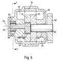
- Rotor 10 is fast with shaft 50 which is also fixed to drive gear 52, and the shaft is bushed at 54 in the pump body.
- Rotor 12 is bushed at 56 on eccentric 58 carried on shaft 60. In both cases the bushes are merely preferable.
- Shaft 60 is on axis 62, which is concentric with the annulus. Shaft 60 is also fast with pinion 64.
- the pinion is meshed with a rack 66 which conveniently is mounted on piston rod 68 carried by piston 70 and slidable in a cylinder diagrammatically illustrated by the reference numeral 72.
- the cylinder may be supplied with fluid at either end via shuttle valve 74.
- the shuttle valve may be connected to pump output or for example the main lubricant gallery of an I.C. engine being supplied by the pump, so that pressure is communicated via the pipe 76 and can act upon the spool 78 resisted by the spring 80.
- fluid flows through the spool, through radial ports in the spool and via the passage 82. It can act upon the piston 70 to displace the rack and turn the pinion.
- line 82 When the pressure is sufficient to displace the spool against the spring, line 82 is placed in communication with waist 84 on the spool and what was the return line 86 is placed in communication with the line 76 so as to reverse the direction of movement of the piston 70.
- rotor 12 is driven indirectly by rotor 10 via the annulus. That is to say the shaft 50 turns the rotor 10 which turns the annulus, and the annulus turns the rotor 12.
- rotor 12 is journalled on an eccentric bush carried on an extension of the shaft 50.
- the annulus is driven, and the two rotors are journalled on respective eccentric bushes each provided with straight tooth spur pinion gears carried on a common axis which is co-axial to the annulus.
- These pinions are located outside the rotors, i.e. at opposite axial ends of the pump, and arranged to be driven through equal and opposite amounts by a gear drive system for example operated by pump hydraulic pressure acting in a piston and cylinder to drive a rack turning the gears.
- a gear drive system for example operated by pump hydraulic pressure acting in a piston and cylinder to drive a rack turning the gears.
Landscapes
- Engineering & Computer Science (AREA)
- Mechanical Engineering (AREA)
- General Engineering & Computer Science (AREA)
- Rotary Pumps (AREA)
- Reciprocating Pumps (AREA)
- Details And Applications Of Rotary Liquid Pumps (AREA)
- Valve Device For Special Equipments (AREA)
- Silver Salt Photography Or Processing Solution Therefor (AREA)
- Vehicle Body Suspensions (AREA)
- Jet Pumps And Other Pumps (AREA)
- Lubrication Of Internal Combustion Engines (AREA)
Claims (7)
- Gerotorpumpe mit einem einzigen Ring (16) und zwei axial aneinander angrenzenden Rotoren (10, 12), die hinsichtlich ihres Relativwinkels zueinander einstellbar sind.
- Pumpe nach Anspruch 1, wobei einer der Rotoren (10) in seiner Winkelposition gegenüber einer Antriebswelle (50) befestigt ist und der andere der Rotoren (12) zwischen extremen Relativpositionen gegenüber dem einen Rotor (10) beweglich ist.
- Pumpe nach Anspruch 1 oder 2, wobei der zweite Rotor (12) auf einer Verlangerung der Welle (50), die den ersten Rotor trägt, gelagert ist.
- Pumpe nach einem der vorangegangenen Ansprüche, wobei der andere der Rotoren (12) auf einem Exzenter (58) gelagert ist, der von einer Welle (60) getragen wird, die auf der Ringachse (24) gelagert ist, und der so angeordnet ist, daß er gedreht werden kann, um auf diese Weise die Phase des anderen Rotors (12) relativ zum einen Rotor (10) zu verschieben.
- Pumpe nach Anspruch 4, wobei die Antriebswelle (50) und die koaxial zum Ring stehende Welle (60) rückseitig aneinander anstoßen.
- Pumpe nach Anspruch 4 oder 5, wobei die andere Welle (60) einen Zapfen (64) trägt, der in ein Kehrrad (66) eingreift.
- Pumpe nach einem der vorangegangenen Ansprüche, wobei der Pumpenkörper (20) mit Einlaßöffnungen (18) an axial gegenüberliegenden Enden und auch mit Ausstoßöffnungen (22) an axial gegenüberliegenden Enden versehen ist.
Applications Claiming Priority (4)
| Application Number | Priority Date | Filing Date | Title |
|---|---|---|---|
| GB929207674A GB9207674D0 (en) | 1992-04-08 | 1992-04-08 | Improvements relating to pumps |
| GB9207674 | 1992-04-08 | ||
| GB929214885A GB9214885D0 (en) | 1992-04-08 | 1992-07-14 | Improvements relating to pumps |
| GB9214885 | 1992-07-14 |
Publications (2)
| Publication Number | Publication Date |
|---|---|
| EP0565340A1 EP0565340A1 (de) | 1993-10-13 |
| EP0565340B1 true EP0565340B1 (de) | 1995-12-13 |
Family
ID=26300673
Family Applications (1)
| Application Number | Title | Priority Date | Filing Date |
|---|---|---|---|
| EP93302689A Expired - Lifetime EP0565340B1 (de) | 1992-04-08 | 1993-04-06 | Innenzahnradpumpe mit regelbarer Liefermenge |
Country Status (11)
| Country | Link |
|---|---|
| EP (1) | EP0565340B1 (de) |
| JP (1) | JPH06508416A (de) |
| AT (1) | ATE131579T1 (de) |
| DE (1) | DE69300999T2 (de) |
| DK (1) | DK0565340T3 (de) |
| ES (1) | ES2083824T3 (de) |
| FI (1) | FI105283B (de) |
| GB (1) | GB2265946B (de) |
| GR (1) | GR3018911T3 (de) |
| NO (2) | NO304752B1 (de) |
| WO (1) | WO1993021443A1 (de) |
Families Citing this family (9)
| Publication number | Priority date | Publication date | Assignee | Title |
|---|---|---|---|---|
| GB2313411B (en) * | 1996-05-25 | 1999-10-13 | Concentric Pumps Ltd | Improvements in drive systems |
| DE10222131C5 (de) * | 2002-05-17 | 2011-08-11 | Schwäbische Hüttenwerke Automotive GmbH & Co. KG, 73433 | Verdrängerpumpe mit Fördervolumenverstellung |
| CN100513787C (zh) | 2004-12-22 | 2009-07-15 | 麦格纳动力系有限公司 | 可变容量的回转泵 |
| GB2430237A (en) * | 2005-06-11 | 2007-03-21 | Concentric Pumps Ltd | Variable output internal gear pump |
| GB2436594A (en) * | 2006-03-28 | 2007-10-03 | Concentric Vfp Ltd | A variable output pump assembly |
| GB2441773B (en) * | 2006-09-15 | 2011-02-23 | Concentric Vfp Ltd | Engine Lubricant Pump Control System |
| GB0620646D0 (en) * | 2006-10-18 | 2006-11-29 | Concentric Vfp Ltd | Pumps with filling slots |
| GB0620648D0 (en) * | 2006-10-18 | 2006-11-29 | Concentric Vfp Ltd | Improvements in gerotor pump performance |
| GB0625765D0 (en) | 2006-12-22 | 2007-02-07 | Concentric Pumps Ltd | Pump |
Family Cites Families (3)
| Publication number | Priority date | Publication date | Assignee | Title |
|---|---|---|---|---|
| GB2120324A (en) * | 1982-05-13 | 1983-11-30 | Neptune Systems Limited | Variable-displacement rotary pump or motor |
| GB8422755D0 (en) * | 1984-09-08 | 1984-10-10 | Concentric Pumps Ltd | Oil pumps |
| GB8706630D0 (en) * | 1987-03-20 | 1987-04-23 | Concentric Pumps Ltd | Variable output oil pump |
-
1993
- 1993-04-05 GB GB9307074A patent/GB2265946B/en not_active Expired - Fee Related
- 1993-04-06 EP EP93302689A patent/EP0565340B1/de not_active Expired - Lifetime
- 1993-04-06 ES ES93302689T patent/ES2083824T3/es not_active Expired - Lifetime
- 1993-04-06 JP JP5518089A patent/JPH06508416A/ja active Pending
- 1993-04-06 WO PCT/GB1993/000720 patent/WO1993021443A1/en active IP Right Grant
- 1993-04-06 AT AT93302689T patent/ATE131579T1/de active
- 1993-04-06 DK DK93302689.0T patent/DK0565340T3/da active
- 1993-04-06 DE DE69300999T patent/DE69300999T2/de not_active Expired - Fee Related
- 1993-12-07 FI FI935470A patent/FI105283B/fi active
- 1993-12-08 NO NO934469A patent/NO304752B1/no not_active IP Right Cessation
- 1993-12-08 NO NO934469D patent/NO934469D0/no unknown
-
1996
- 1996-02-07 GR GR960400317T patent/GR3018911T3/el unknown
Also Published As
| Publication number | Publication date |
|---|---|
| GR3018911T3 (en) | 1996-05-31 |
| NO934469L (no) | 1993-12-08 |
| FI105283B (fi) | 2000-07-14 |
| JPH06508416A (ja) | 1994-09-22 |
| FI935470A0 (fi) | 1993-12-07 |
| DE69300999T2 (de) | 1996-05-23 |
| FI935470A (fi) | 1993-12-07 |
| NO934469D0 (no) | 1993-12-08 |
| DK0565340T3 (da) | 1996-02-19 |
| WO1993021443A1 (en) | 1993-10-28 |
| DE69300999D1 (de) | 1996-01-25 |
| GB9307074D0 (en) | 1993-05-26 |
| EP0565340A1 (de) | 1993-10-13 |
| GB2265946B (en) | 1995-01-18 |
| GB2265946A (en) | 1993-10-13 |
| NO304752B1 (no) | 1999-02-08 |
| ATE131579T1 (de) | 1995-12-15 |
| ES2083824T3 (es) | 1996-04-16 |
Similar Documents
| Publication | Publication Date | Title |
|---|---|---|
| US3680989A (en) | Hydraulic pump or motor | |
| US4480971A (en) | Two-speed gerotor motor | |
| US7832997B2 (en) | Variable capacity gerotor pump | |
| EP0213154B1 (de) | Fluidvorrichtung mit rotierender bewegung | |
| US3106163A (en) | Pumps, motors and like devices | |
| EP0565340B1 (de) | Innenzahnradpumpe mit regelbarer Liefermenge | |
| US3597128A (en) | Hydraulic device having hydraulically balanced commutation | |
| US3910732A (en) | Gerotor pump or motor | |
| US3598509A (en) | Hydraulic device | |
| US3473437A (en) | Rotary slide valve for fluid motors and pumps | |
| US4887956A (en) | Variable output oil pump | |
| NO140479B (no) | Rotasjonsstempelmotor. | |
| EP0033544A2 (de) | Innenachsige Zahnradmaschine mit Verteilungsmitteln | |
| US6672850B2 (en) | Torque control oil pump with low parasitic loss and rapid pressure transient response | |
| US4778361A (en) | Variable output gerotor pump | |
| EP0076033A1 (de) | Innenzahnradpumpe mit regelbarer Liefermenge | |
| US3456559A (en) | Rotary device | |
| CA2046376A1 (en) | Gerotor pumps | |
| US4156585A (en) | Gerotor device with porting through eccentric drive | |
| WO1991019902A1 (en) | Hydraulic rotary radial piston pumps | |
| EP0276680A2 (de) | Ventil für Sternmotor mit zwei Geschwindigkeiten | |
| US2805548A (en) | Hydraulic pump or motor | |
| GB2163217A (en) | An internally meshing gear- pump or motor | |
| US20150204324A1 (en) | Drive Assembly for a Rotary Fluid Pressure Device | |
| AU5781901A (en) | Variable displacement pump |
Legal Events
| Date | Code | Title | Description |
|---|---|---|---|
| PUAI | Public reference made under article 153(3) epc to a published international application that has entered the european phase |
Free format text: ORIGINAL CODE: 0009012 |
|
| AK | Designated contracting states |
Kind code of ref document: A1 Designated state(s): AT BE CH DE DK ES FR GB GR IE IT LI LU MC NL PT SE |
|
| 17P | Request for examination filed |
Effective date: 19940218 |
|
| 17Q | First examination report despatched |
Effective date: 19950215 |
|
| GRAA | (expected) grant |
Free format text: ORIGINAL CODE: 0009210 |
|
| AK | Designated contracting states |
Kind code of ref document: B1 Designated state(s): AT BE CH DE DK ES FR GB GR IE IT LI LU MC NL PT SE |
|
| REF | Corresponds to: |
Ref document number: 131579 Country of ref document: AT Date of ref document: 19951215 Kind code of ref document: T |
|
| REG | Reference to a national code |
Ref country code: IE Ref legal event code: FG4D Free format text: 66545 |
|
| REF | Corresponds to: |
Ref document number: 69300999 Country of ref document: DE Date of ref document: 19960125 |
|
| ET | Fr: translation filed | ||
| ITF | It: translation for a ep patent filed |
Owner name: ING. A. GIAMBROCONO & C. S.R.L. |
|
| REG | Reference to a national code |
Ref country code: DK Ref legal event code: T3 |
|
| REG | Reference to a national code |
Ref country code: CH Ref legal event code: NV Representative=s name: TROESCH SCHEIDEGGER WERNER AG |
|
| REG | Reference to a national code |
Ref country code: ES Ref legal event code: FG2A Ref document number: 2083824 Country of ref document: ES Kind code of ref document: T3 |
|
| REG | Reference to a national code |
Ref country code: GR Ref legal event code: FG4A Free format text: 3018911 |
|
| SC4A | Pt: translation is available |
Free format text: 960209 AVAILABILITY OF NATIONAL TRANSLATION |
|
| PLBE | No opposition filed within time limit |
Free format text: ORIGINAL CODE: 0009261 |
|
| STAA | Information on the status of an ep patent application or granted ep patent |
Free format text: STATUS: NO OPPOSITION FILED WITHIN TIME LIMIT |
|
| 26N | No opposition filed | ||
| PGFP | Annual fee paid to national office [announced via postgrant information from national office to epo] |
Ref country code: GB Payment date: 20000331 Year of fee payment: 8 |
|
| PGFP | Annual fee paid to national office [announced via postgrant information from national office to epo] |
Ref country code: PT Payment date: 20000405 Year of fee payment: 8 |
|
| PGFP | Annual fee paid to national office [announced via postgrant information from national office to epo] |
Ref country code: DE Payment date: 20000410 Year of fee payment: 8 |
|
| PGFP | Annual fee paid to national office [announced via postgrant information from national office to epo] |
Ref country code: DK Payment date: 20000412 Year of fee payment: 8 Ref country code: AT Payment date: 20000412 Year of fee payment: 8 |
|
| PGFP | Annual fee paid to national office [announced via postgrant information from national office to epo] |
Ref country code: CH Payment date: 20000414 Year of fee payment: 8 |
|
| PGFP | Annual fee paid to national office [announced via postgrant information from national office to epo] |
Ref country code: GR Payment date: 20000417 Year of fee payment: 8 |
|
| PGFP | Annual fee paid to national office [announced via postgrant information from national office to epo] |
Ref country code: LU Payment date: 20000419 Year of fee payment: 8 |
|
| PGFP | Annual fee paid to national office [announced via postgrant information from national office to epo] |
Ref country code: IE Payment date: 20000426 Year of fee payment: 8 |
|
| PGFP | Annual fee paid to national office [announced via postgrant information from national office to epo] |
Ref country code: ES Payment date: 20000427 Year of fee payment: 8 Ref country code: SE Payment date: 20000427 Year of fee payment: 8 |
|
| PGFP | Annual fee paid to national office [announced via postgrant information from national office to epo] |
Ref country code: FR Payment date: 20000428 Year of fee payment: 8 Ref country code: NL Payment date: 20000428 Year of fee payment: 8 |
|
| PGFP | Annual fee paid to national office [announced via postgrant information from national office to epo] |
Ref country code: MC Payment date: 20000502 Year of fee payment: 8 |
|
| PGFP | Annual fee paid to national office [announced via postgrant information from national office to epo] |
Ref country code: BE Payment date: 20000622 Year of fee payment: 8 |
|
| PG25 | Lapsed in a contracting state [announced via postgrant information from national office to epo] |
Ref country code: LU Free format text: LAPSE BECAUSE OF NON-PAYMENT OF DUE FEES Effective date: 20010406 Ref country code: IE Free format text: LAPSE BECAUSE OF NON-PAYMENT OF DUE FEES Effective date: 20010406 Ref country code: GB Free format text: LAPSE BECAUSE OF NON-PAYMENT OF DUE FEES Effective date: 20010406 Ref country code: DK Free format text: LAPSE BECAUSE OF NON-PAYMENT OF DUE FEES Effective date: 20010406 Ref country code: AT Free format text: LAPSE BECAUSE OF NON-PAYMENT OF DUE FEES Effective date: 20010406 |
|
| PG25 | Lapsed in a contracting state [announced via postgrant information from national office to epo] |
Ref country code: SE Free format text: LAPSE BECAUSE OF NON-PAYMENT OF DUE FEES Effective date: 20010407 Ref country code: ES Free format text: LAPSE BECAUSE OF NON-PAYMENT OF DUE FEES Effective date: 20010407 |
|
| PG25 | Lapsed in a contracting state [announced via postgrant information from national office to epo] |
Ref country code: MC Free format text: LAPSE BECAUSE OF NON-PAYMENT OF DUE FEES Effective date: 20010430 Ref country code: GR Free format text: LAPSE BECAUSE OF NON-PAYMENT OF DUE FEES Effective date: 20010430 Ref country code: FR Free format text: THE PATENT HAS BEEN ANNULLED BY A DECISION OF A NATIONAL AUTHORITY Effective date: 20010430 Ref country code: BE Free format text: LAPSE BECAUSE OF NON-PAYMENT OF DUE FEES Effective date: 20010430 |
|
| PG25 | Lapsed in a contracting state [announced via postgrant information from national office to epo] |
Ref country code: LI Free format text: LAPSE BECAUSE OF NON-PAYMENT OF DUE FEES Effective date: 20010505 Ref country code: CH Free format text: LAPSE BECAUSE OF NON-PAYMENT OF DUE FEES Effective date: 20010505 |
|
| BERE | Be: lapsed |
Owner name: CONCENTRIC PUMPS LTD Effective date: 20010430 |
|
| PG25 | Lapsed in a contracting state [announced via postgrant information from national office to epo] |
Ref country code: PT Free format text: LAPSE BECAUSE OF NON-PAYMENT OF DUE FEES Effective date: 20011031 |
|
| PG25 | Lapsed in a contracting state [announced via postgrant information from national office to epo] |
Ref country code: NL Free format text: LAPSE BECAUSE OF NON-PAYMENT OF DUE FEES Effective date: 20011101 |
|
| GBPC | Gb: european patent ceased through non-payment of renewal fee |
Effective date: 20010406 |
|
| EUG | Se: european patent has lapsed |
Ref document number: 93302689.0 |
|
| REG | Reference to a national code |
Ref country code: DK Ref legal event code: EBP |
|
| REG | Reference to a national code |
Ref country code: CH Ref legal event code: PL |
|
| NLV4 | Nl: lapsed or anulled due to non-payment of the annual fee |
Effective date: 20011101 |
|
| PG25 | Lapsed in a contracting state [announced via postgrant information from national office to epo] |
Ref country code: DE Free format text: LAPSE BECAUSE OF NON-PAYMENT OF DUE FEES Effective date: 20020201 |
|
| REG | Reference to a national code |
Ref country code: FR Ref legal event code: ST |
|
| REG | Reference to a national code |
Ref country code: IE Ref legal event code: MM4A |
|
| REG | Reference to a national code |
Ref country code: PT Ref legal event code: MM4A Free format text: LAPSE DUE TO NON-PAYMENT OF FEES Effective date: 20011031 |
|
| REG | Reference to a national code |
Ref country code: ES Ref legal event code: FD2A Effective date: 20030203 |
|
| PG25 | Lapsed in a contracting state [announced via postgrant information from national office to epo] |
Ref country code: IT Free format text: LAPSE BECAUSE OF NON-PAYMENT OF DUE FEES Effective date: 20050406 |