EP0565328B1 - Method and apparatus for determining belt velocity - Google Patents
Method and apparatus for determining belt velocity Download PDFInfo
- Publication number
- EP0565328B1 EP0565328B1 EP93302649A EP93302649A EP0565328B1 EP 0565328 B1 EP0565328 B1 EP 0565328B1 EP 93302649 A EP93302649 A EP 93302649A EP 93302649 A EP93302649 A EP 93302649A EP 0565328 B1 EP0565328 B1 EP 0565328B1
- Authority
- EP
- European Patent Office
- Prior art keywords
- belt
- velocity
- apertures
- sensor
- array
- Prior art date
- Legal status (The legal status is an assumption and is not a legal conclusion. Google has not performed a legal analysis and makes no representation as to the accuracy of the status listed.)
- Expired - Lifetime
Links
- 238000000034 method Methods 0.000 title claims description 23
- 238000005286 illumination Methods 0.000 claims description 12
- 108091008695 photoreceptors Proteins 0.000 claims description 12
- 238000005070 sampling Methods 0.000 claims description 12
- 238000009826 distribution Methods 0.000 claims description 10
- 238000004364 calculation method Methods 0.000 claims description 8
- 238000006073 displacement reaction Methods 0.000 description 5
- 238000005259 measurement Methods 0.000 description 4
- 238000004422 calculation algorithm Methods 0.000 description 3
- 238000012545 processing Methods 0.000 description 3
- 238000013461 design Methods 0.000 description 2
- 238000011161 development Methods 0.000 description 2
- 238000010586 diagram Methods 0.000 description 2
- 239000000835 fiber Substances 0.000 description 2
- 238000013459 approach Methods 0.000 description 1
- 238000003491 array Methods 0.000 description 1
- 239000003990 capacitor Substances 0.000 description 1
- 238000004140 cleaning Methods 0.000 description 1
- 230000007547 defect Effects 0.000 description 1
- 230000001419 dependent effect Effects 0.000 description 1
- 238000009795 derivation Methods 0.000 description 1
- 238000001514 detection method Methods 0.000 description 1
- 238000003384 imaging method Methods 0.000 description 1
- 238000000691 measurement method Methods 0.000 description 1
- 238000012986 modification Methods 0.000 description 1
- 230000004048 modification Effects 0.000 description 1
- 238000012544 monitoring process Methods 0.000 description 1
- 230000003287 optical effect Effects 0.000 description 1
- 238000004080 punching Methods 0.000 description 1
- 238000000926 separation method Methods 0.000 description 1
- 238000012546 transfer Methods 0.000 description 1
Images


Classifications
-
- G—PHYSICS
- G03—PHOTOGRAPHY; CINEMATOGRAPHY; ANALOGOUS TECHNIQUES USING WAVES OTHER THAN OPTICAL WAVES; ELECTROGRAPHY; HOLOGRAPHY
- G03G—ELECTROGRAPHY; ELECTROPHOTOGRAPHY; MAGNETOGRAPHY
- G03G15/00—Apparatus for electrographic processes using a charge pattern
- G03G15/50—Machine control of apparatus for electrographic processes using a charge pattern, e.g. regulating differents parts of the machine, multimode copiers, microprocessor control
- G03G15/5033—Machine control of apparatus for electrographic processes using a charge pattern, e.g. regulating differents parts of the machine, multimode copiers, microprocessor control by measuring the photoconductor characteristics, e.g. temperature, or the characteristics of an image on the photoconductor
-
- G—PHYSICS
- G01—MEASURING; TESTING
- G01D—MEASURING NOT SPECIALLY ADAPTED FOR A SPECIFIC VARIABLE; ARRANGEMENTS FOR MEASURING TWO OR MORE VARIABLES NOT COVERED IN A SINGLE OTHER SUBCLASS; TARIFF METERING APPARATUS; MEASURING OR TESTING NOT OTHERWISE PROVIDED FOR
- G01D5/00—Mechanical means for transferring the output of a sensing member; Means for converting the output of a sensing member to another variable where the form or nature of the sensing member does not constrain the means for converting; Transducers not specially adapted for a specific variable
- G01D5/26—Mechanical means for transferring the output of a sensing member; Means for converting the output of a sensing member to another variable where the form or nature of the sensing member does not constrain the means for converting; Transducers not specially adapted for a specific variable characterised by optical transfer means, i.e. using infrared, visible, or ultraviolet light
-
- G—PHYSICS
- G01—MEASURING; TESTING
- G01P—MEASURING LINEAR OR ANGULAR SPEED, ACCELERATION, DECELERATION, OR SHOCK; INDICATING PRESENCE, ABSENCE, OR DIRECTION, OF MOVEMENT
- G01P3/00—Measuring linear or angular speed; Measuring differences of linear or angular speeds
- G01P3/36—Devices characterised by the use of optical means, e.g. using infrared, visible, or ultraviolet light
-
- G—PHYSICS
- G03—PHOTOGRAPHY; CINEMATOGRAPHY; ANALOGOUS TECHNIQUES USING WAVES OTHER THAN OPTICAL WAVES; ELECTROGRAPHY; HOLOGRAPHY
- G03G—ELECTROGRAPHY; ELECTROPHOTOGRAPHY; MAGNETOGRAPHY
- G03G2215/00—Apparatus for electrophotographic processes
- G03G2215/00025—Machine control, e.g. regulating different parts of the machine
- G03G2215/00071—Machine control, e.g. regulating different parts of the machine by measuring the photoconductor or its environmental characteristics
- G03G2215/00075—Machine control, e.g. regulating different parts of the machine by measuring the photoconductor or its environmental characteristics the characteristic being its speed
-
- G—PHYSICS
- G03—PHOTOGRAPHY; CINEMATOGRAPHY; ANALOGOUS TECHNIQUES USING WAVES OTHER THAN OPTICAL WAVES; ELECTROGRAPHY; HOLOGRAPHY
- G03G—ELECTROGRAPHY; ELECTROPHOTOGRAPHY; MAGNETOGRAPHY
- G03G2215/00—Apparatus for electrophotographic processes
- G03G2215/01—Apparatus for electrophotographic processes for producing multicoloured copies
- G03G2215/0151—Apparatus for electrophotographic processes for producing multicoloured copies characterised by the technical problem
- G03G2215/0158—Colour registration
Definitions
- the present invention relates to a method and an apparatus for determining the velocity of a belt moving in a process direction as defined in the preambles of claims 1 and 6 respectively and, more particularly, to a method or apparatus for sensing displacement and velocity variations of a photoreceptor belt used as the image recording member of a copier or printer.
- banding is a defect observable in output copies resulting from velocity variations in the speed of the moving photoreceptor.
- the velocity variations create a misplacement of scan image lines in the slow scan or process direction.
- the output copies must be virtually band free, requiring holding velocity variations to less than 1%, which is in the order of 1 ⁇ m spatial variation at certain frequencies and for certain systems.
- newer printers incorporating light scanning sources such as Raster Output Scanners (ROS) or image bars, create successive color exposure frames on a photoreceptor during a single pass.
- ROS Raster Output Scanners
- each of the successive color images must be in registration, within tolerances of approximately 125 ⁇ m (0.005 inch). This precise tolerance requirement, in turn, necessitates a very accurate spacing between exposure frames; ideally the separation between two frames should be an integer number of scan lines apart and, therefore the spacing must be accurate to within a similar fraction of a raster line width, or about 40 to 80 ⁇ m.
- the present invention is directed towards an improved method for detecting photoreceptor velocity displacement variation and for generating precise signals which are used to compensate for the photoreceptor speed and position.
- the invention represents an improvement over the prior art motion sensing techniques disclosed, for example, in US-A-4,837,636.
- the '636 patent disclosed the use of a linear CCD array which sensed the edge of the image of a plurality of holes projected onto the array.
- intensity variations between projected images and noise produced by stray light and poorly defined line edges reduced the ability to precisely define the edge, and, therefore, accurately characterize the image velocity within the accuracies required.
- the resolution of the measurement system was limited to the resolution of the CCD array.
- the present invention presents an improvement by using a centroid algorithm to calculate projected hole positions. This approach is less sensitive to uniformity variations and noise, and exceeds the resolution of the segmented array of the prior art by at least an order of magnitude.
- the present invention relates to a method for determining the velocity of a belt according to claim 1 of the appended claims.
- the invention further provides an apparatus for determining the velocity of a belt, according to claim 6 of the appended claims.
- the invention further provides a printer according to claim 9 of the appended claims.
- Figure 1 shows a photoreceptor 10 having a length sufficient to accept an integral number of full page image areas I 1 - I n , represented by dashed lines. These image areas are formed by exposure from an appropriate scanning source such as a Raster Output Scanner (ROS) or a linear LED print bar array, as is known in the art.
- the belt is charged and exposed in a multiple pass mode or in a single pass mode.
- conventional xerographic stations charge, development, transfer, fusing, cleaning
- Use in a single pass system requires a set of charge and development stations associated with each image frame.
- a plurality of holes 12 are formed in a row along one edge of belt 10, outside the image area.
- the holes 12 extend around the circumference of belt 10 and lie in a row parallel to the process direction.
- a hole sensing system 20 is positioned as shown in Figure 1.
- Figure 2 shows a side view of system 20 and a portion of the belt.
- Figure 3 shows a top view and Figure 4 an end view.
- system 20 comprises a linear segmented array 22 which, in a preferred embodiment, is a CCD array, but may take other forms of segmented position sensors with analog or digital output, such as fiber optic bundles or other light pipe devices which address individual photodiodes.
- Array 22 has a plurality of pixels 22A arranged in a linear row. The longitudinal axis of the row of pixels 22A is substantially parallel to the axis of movement of holes 12, the optical center of pixels 22A is in line with the center of each hole 12.
- Lamp 24 has an aperture length which is at least sufficient to provide substantially equal illumination along the entire length of array 22, with the longitudinal axis of array 22 being substantially parallel to the longitudinal axis of lamp 24. Holes 12 are separated by a distance such that the hole-to-hole spacing is less than the length of array 22.
- Array 22 is mounted in a predetermined space relationship beneath belt 10 and in the viewing nip of light from lamp 24, directed through each of the holes 12.
- photoreceptor motion is sensed by monitoring the position of holes 12 illuminated by lamp 24, as sensed along the length of array 22.
- the light passing through each hole is transmitted by a relay lens (not shown) and imaged onto the array 22.
- the imaged holes which are approximately Gaussian in cross-section, move across the array as shown in Figure 6.
- the light irradiance distribution of the imaged holes is sampled and the centroid of the distribution is calculated by using a centroid algorithm described in further detail below.
- Figure 5 shows the flow diagram which is used to track the position of the belt.
- the illumination sensed by each of the array pixels within the viewing nip of lamp 24, which is substantially Gaussian is measured during a sampling period, and the voltage developed by any one of the capacitors of the array is proportional to the time average light intensity of the lamp as viewed through the aperture.
- the pixel arrays are interrogated in parallel in a preferred embodiment, and a segmented data stream consisting of voltage measurements proportional to the light intensity distribution incident upon the corresponding sensors is generated.
- the data stream output is then digitized in A/D convertor 30 and the irradiance distribution centroid is calculated in centroid processor 32.
- a number of pixel elements view the lamp 24 output.
- Data in the array begins to be clocked out at the chosen sampling rate.
- the sampling rate identified as ⁇ t, will vary depending on the number of pixels in the array, the clock speed of the shift register in the array, the time to perform the centroid calculations, and whether the array has parallel or serial addressability.
- the logic design of Figure 5 is for an array that uses parallel addressability for each pixel.
- the intensity distribution along the vertical axis of array 20 is Gaussian; i.e. bell shaped, and the centroid appears at its peak. This characteristic has the advantage over prior art methods, in that the signals are not strongly affected by noise.
- centroid processor 32 which contains the circuitry for performing the calculations for the sampled distribution.
- centroid is derived according to the expression: where:
- Figure 6a a scan of array 22, through hole 12a, at a time t 0 .
- the hole centroid is found to occur at the pixel designated as P 0 .
- This hole position is calculated to a fraction of the pixel spacing, conventionally 100 ⁇ m.
- Figure 6b shows a scan at a time t 1 , the hole centroid using equation 1 at pixel P 1 .
- V pr (P 1 - P 0 )( ⁇ x) t 1 - t 0
- ⁇ x pixel spacing
- the velocity of the belt is thus updated each time the array is scanned (during every time interval ⁇ t).
- Either the velocity or incremental belt displacement can then be fed back to a servo system controlling the speed and position of the belt.
- the displacement and velocity are adjusted by comparing the measured velocity (V p0 ) and or the incremental displacement ( ⁇ x i ) to the correct velocity and incremental position of the belt.
- the actual belt position can be used uncorrected and the leading edge of images I 1 - I n can be adjusted.
- the belt velocity must be actually calculated with each measurement.
- ⁇ X (V pr ) ( ⁇ t)
- This calculation allows only a portion of the CCD array to be interrogated which speeds processing time. In other words, a smaller number of sampling periods are required since the prediction of the centroid location will be accurate enough to allow interrogation of a small group of pixels at a predetermined future position. For example, for a time ⁇ t of 0.0001 sec. and a V pr at 10 inches/sec. (25cm/sec), a measurement of the photoreceptor position would occur every .001 inches (25.4 ⁇ m).
- Equation 3 can also be used to determine when the leading holes reach the end of the array and begin to exit the sensing area (Fig. 7).
- a calculation is made to determine which pixel on array 20 will view the next hole entering the leading edge of the array.
- the sensing calculations are then transferred from this pixel group to the pixel group which will view the next hole about to enter the lead edge of the sensor array.
- This calculation is made as a function of the hole spacing on the photoreceptor divided by the array pixel spacing.
- the accuracy of this measurement technique is dependent on the number of CCD pixels 22A that are contained in the full width-half max of the hole image presented onto the CCD array and the full width-half max dimension and, under certain circumstances, has been measured to less than 0.5 ⁇ m.
- a sample design that would yield this accuracy and be practical with respect to manufacturability and machine robustness is as follows. Hole 12 punched in the belt would be 0.5 mm to allow easy punching and prevent clogging with toner. For 1X imaging optics, a CCD spacing of 100 ⁇ m would yield the desired accuracy ( ⁇ 0.5 microns) for a CCD or similar sensing array having S/N ratio of >200. Holes punched approximately every inch (every 25.4 mm) would allow for array lengths of less than 2 inches (50.8 mm), or 1024 elements. Using a centroid algorithm to determine projected image position has been shown analytically and empirically to be less sensitive to uniformity variations and noise, and exceeds the resolution of the segmented sensor by at least an order of magnitude.
- This invention is not limited to the use of CCD array sensors. It can be applied to any form of segmented position sensor with digital or analog output, to fiber optic bundles, or other "light pipe” devices addressing individual photodiodes.
- the apertures formed in the belt comprise equally spaced holes 12, other non-circular apertures could be used with different spacings therebetween.
- the "aperture” could also be a light transmissive segment formed in the belt. The velocity of the belt is determined by the movement of the same target across the array, irrespective of shape or size.
Landscapes
- Physics & Mathematics (AREA)
- General Physics & Mathematics (AREA)
- Engineering & Computer Science (AREA)
- Microelectronics & Electronic Packaging (AREA)
- Electromagnetism (AREA)
- Power Engineering (AREA)
- Control Or Security For Electrophotography (AREA)
- Electrostatic Charge, Transfer And Separation In Electrography (AREA)
- Control Of Velocity Or Acceleration (AREA)
- Length Measuring Devices By Optical Means (AREA)
Description
- The present invention relates to a method and an apparatus for determining the velocity of a belt moving in a process direction as defined in the preambles of claims 1 and 6 respectively and, more particularly, to a method or apparatus for sensing displacement and velocity variations of a photoreceptor belt used as the image recording member of a copier or printer.
- A serious problem in prior art document reproduction machines is a phenomena referred to as "banding". Banding is a defect observable in output copies resulting from velocity variations in the speed of the moving photoreceptor. The velocity variations create a misplacement of scan image lines in the slow scan or process direction. For many printer applications, the output copies must be virtually band free, requiring holding velocity variations to less than 1%, which is in the order of 1µm spatial variation at certain frequencies and for certain systems. In addition, newer printers incorporating light scanning sources, such as Raster Output Scanners (ROS) or image bars, create successive color exposure frames on a photoreceptor during a single pass. The leading edges of each of the successive color images must be in registration, within tolerances of approximately 125 µm (0.005 inch). This precise tolerance requirement, in turn, necessitates a very accurate spacing between exposure frames; ideally the separation between two frames should be an integer number of scan lines apart and, therefore the spacing must be accurate to within a similar fraction of a raster line width, or about 40 to 80 µm.
- The present invention is directed towards an improved method for detecting photoreceptor velocity displacement variation and for generating precise signals which are used to compensate for the photoreceptor speed and position. The invention represents an improvement over the prior art motion sensing techniques disclosed, for example, in US-A-4,837,636. The '636 patent disclosed the use of a linear CCD array which sensed the edge of the image of a plurality of holes projected onto the array. However, intensity variations between projected images and noise produced by stray light and poorly defined line edges reduced the ability to precisely define the edge, and, therefore, accurately characterize the image velocity within the accuracies required. Further, the resolution of the measurement system was limited to the resolution of the CCD array. The present invention presents an improvement by using a centroid algorithm to calculate projected hole positions. This approach is less sensitive to uniformity variations and noise, and exceeds the resolution of the segmented array of the prior art by at least an order of magnitude.
- The present invention relates to a method for determining the velocity of a belt according to claim 1 of the appended claims.
- The invention further provides an apparatus for determining the velocity of a belt, according to claim 6 of the appended claims.
- The invention further provides a printer according to claim 9 of the appended claims.
- An embodiment of the invention will now be described, by way of example, with reference to the drawings, in which:
- FIG. 1 is a top perspective view of the motion sensor detector apparatus positioned adjacent a photoreceptor belt in a printing environment;
- FIG. 2 is a side view of the motion sensor detection apparatus;
- FIG. 3 is a top view of FIG. 2 combined with a block diagram of the sensing and calculation circuitry;
- FIG. 4 is an end view of FIG. 2;
- FIG. 5 is a functional flow chart showing the application of a centroid processor to the outputs of the light detector; and
- FIGS. 6a and 6b show scans of a pixel array at two different times.
-
- Figure 1 shows a
photoreceptor 10 having a length sufficient to accept an integral number of full page image areas I1 - In, represented by dashed lines. These image areas are formed by exposure from an appropriate scanning source such as a Raster Output Scanner (ROS) or a linear LED print bar array, as is known in the art. The belt is charged and exposed in a multiple pass mode or in a single pass mode. For either form of usage, conventional xerographic stations (charge, development, transfer, fusing, cleaning) are located in belt proximity, as is conventional in the prior art. Use in a single pass system requires a set of charge and development stations associated with each image frame. In the multi-pass (black only) environment, variations in the velocity ofbelt 10 would result in the aforementioned banding defined in output prints. In a single pass color system, position variations would also result in misregistration of the image areas I1 - In. According to the present invention, a plurality ofholes 12 are formed in a row along one edge ofbelt 10, outside the image area. Theholes 12 extend around the circumference ofbelt 10 and lie in a row parallel to the process direction. Ahole sensing system 20 is positioned as shown in Figure 1. Figure 2 shows a side view ofsystem 20 and a portion of the belt. Figure 3 shows a top view and Figure 4 an end view. As shown in Figures 2-4,system 20 comprises a linearsegmented array 22 which, in a preferred embodiment, is a CCD array, but may take other forms of segmented position sensors with analog or digital output, such as fiber optic bundles or other light pipe devices which address individual photodiodes.Array 22 has a plurality ofpixels 22A arranged in a linear row. The longitudinal axis of the row ofpixels 22A is substantially parallel to the axis of movement ofholes 12, the optical center ofpixels 22A is in line with the center of eachhole 12.Lamp 24 has an aperture length which is at least sufficient to provide substantially equal illumination along the entire length ofarray 22, with the longitudinal axis ofarray 22 being substantially parallel to the longitudinal axis oflamp 24.Holes 12 are separated by a distance such that the hole-to-hole spacing is less than the length ofarray 22.Array 22 is mounted in a predetermined space relationship beneathbelt 10 and in the viewing nip of light fromlamp 24, directed through each of theholes 12. - In operation, photoreceptor motion is sensed by monitoring the position of
holes 12 illuminated bylamp 24, as sensed along the length ofarray 22. The light passing through each hole is transmitted by a relay lens (not shown) and imaged onto thearray 22. The imaged holes, which are approximately Gaussian in cross-section, move across the array as shown in Figure 6. The light irradiance distribution of the imaged holes is sampled and the centroid of the distribution is calculated by using a centroid algorithm described in further detail below. - Figure 5 shows the flow diagram which is used to track the position of the belt. Referring to Figures 3 and 5, as
hole 12A moves over the lead edge ofarray 20, the illumination sensed by each of the array pixels within the viewing nip oflamp 24, which is substantially Gaussian, is measured during a sampling period, and the voltage developed by any one of the capacitors of the array is proportional to the time average light intensity of the lamp as viewed through the aperture. The pixel arrays are interrogated in parallel in a preferred embodiment, and a segmented data stream consisting of voltage measurements proportional to the light intensity distribution incident upon the corresponding sensors is generated. The data stream output is then digitized in A/D convertor 30 and the irradiance distribution centroid is calculated incentroid processor 32. As hole 12B moves across the leading edge ofarray 20, a number of pixel elements view thelamp 24 output. Data in the array begins to be clocked out at the chosen sampling rate. The sampling rate, identified as Δt, will vary depending on the number of pixels in the array, the clock speed of the shift register in the array, the time to perform the centroid calculations, and whether the array has parallel or serial addressability. The logic design of Figure 5 is for an array that uses parallel addressability for each pixel. The intensity distribution along the vertical axis ofarray 20 is Gaussian; i.e. bell shaped, and the centroid appears at its peak. This characteristic has the advantage over prior art methods, in that the signals are not strongly affected by noise. - Continuing with the description, the data from
array 20 is digitized using A/D convertor 30. 8 bits has proven to be sufficient. The output is sent tocentroid processor 32, which contains the circuitry for performing the calculations for the sampled distribution. The centroid is derived according to the expression:where: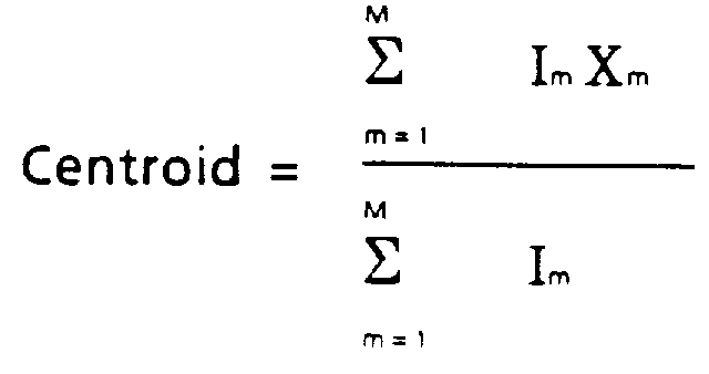
- Im = the irradiance at pixel m,
- Xm = the position of pixel m, and
- M = total number of pixels being illuminated during sampling interval. The derivation of this formula is found, for example, in an article entitled, "Sampling Theorem for Geometric Moment Determination and its Application to a Laser Beam Position Detector", by Robert Loce and Ronald Jodoin, published in Applied Optics, Vol. 29, No. 6, September 10, 1990.
-
- Thus, in considering Figure 6, there is shown in Figure 6a a scan of
array 22, through hole 12a, at a time t0. By equation 1, the hole centroid is found to occur at the pixel designated as P0. This would be equivalent to a pixel m in equation 1. This hole position is calculated to a fraction of the pixel spacing, conventionally 100 µm. Figure 6b shows a scan at a time t1, the hole centroid using equation 1 at pixel P1. Belt velocity (Vpr) can thus be calculated by the equation:
Δx = pixel spacing
The velocity of the belt is thus updated each time the array is scanned (during every time interval Δt). Either the velocity or incremental belt displacement can then be fed back to a servo system controlling the speed and position of the belt. The displacement and velocity are adjusted by comparing the measured velocity (Vp0) and or the incremental displacement (δxi) to the correct velocity and incremental position of the belt. Alternatively, the actual belt position can be used uncorrected and the leading edge of images I1 - In can be adjusted. For serial processing, the belt velocity must be actually calculated with each measurement. However, for the parallel processing mode, the initial centroid location data can be used to predict appropriate locations of successive hole positions using the expression: - Equation 3 can also be used to determine when the leading holes reach the end of the array and begin to exit the sensing area (Fig. 7). A calculation is made to determine which pixel on
array 20 will view the next hole entering the leading edge of the array. The sensing calculations are then transferred from this pixel group to the pixel group which will view the next hole about to enter the lead edge of the sensor array. This calculation is made as a function of the hole spacing on the photoreceptor divided by the array pixel spacing. The accuracy of this measurement technique is dependent on the number ofCCD pixels 22A that are contained in the full width-half max of the hole image presented onto the CCD array and the full width-half max dimension and, under certain circumstances, has been measured to less than 0.5 µm. A sample design that would yield this accuracy and be practical with respect to manufacturability and machine robustness is as follows.Hole 12 punched in the belt would be 0.5 mm to allow easy punching and prevent clogging with toner. For 1X imaging optics, a CCD spacing of 100 µm would yield the desired accuracy (<0.5 microns) for a CCD or similar sensing array having S/N ratio of >200. Holes punched approximately every inch (every 25.4 mm) would allow for array lengths of less than 2 inches (50.8 mm), or 1024 elements. Using a centroid algorithm to determine projected image position has been shown analytically and empirically to be less sensitive to uniformity variations and noise, and exceeds the resolution of the segmented sensor by at least an order of magnitude. This is a significant improvement over the prior art. This invention is not limited to the use of CCD array sensors. It can be applied to any form of segmented position sensor with digital or analog output, to fiber optic bundles, or other "light pipe" devices addressing individual photodiodes. - While the invention has been described with reference to the structures disclosed, it is not confined to the details set forth, but is intended to cover such modifications or changes as they come within the scope of the following claims.
- For example, while the apertures formed in the belt comprise equally spaced
holes 12, other non-circular apertures could be used with different spacings therebetween. Further, the "aperture" could also be a light transmissive segment formed in the belt. The velocity of the belt is determined by the movement of the same target across the array, irrespective of shape or size.
Claims (9)
- A method for determining the velocity of a belt moving in a process direction, said belt characterized as having a series of apertures along an edge extending in a row which is parallel to said process direction, the method comprising the steps of:the method characterized by the steps ofpositioning an illumination source adjacent said belt so that a band of illumination is directed along said row of apertures, at least two of said apertures being simultaneously illuminated, andplacing a segmented position sensor on the side of the belt opposite that occupied by said illumination source, said position sensor aligned so that illumination from said illumination source is viewed over a group of sensor segments through at least two of said apertures as the belt moves therepast, said sensors producing output signals representing the light intensity distribution sensed by said group of sensor signals during a sampling period,calculating the centroid positions of said intensity distributions from at least two sampling periods, andcalculating the velocity of the belt using the centroid position information from said at least two sampling periods.
- The method of claim 1 further including the step of predicting future positions of said aperture as said belt moves at said process speed, said new position signals reflecting the actual speed of the belt.
- The method of claim 1 or claim 2 further including the steps of:determining the time at which an aperture being viewed by said sensor is approaching the end of the sensor, andshifting the sampling from the group of pixels viewing said exiting aperture to the array of pixels which will come into view of the aperture about to enter the leading edge of said sensor array.
- The method of claim 1, 2 or 3 including the further step of using said velocity calculations to correct the belt velocity and or position.
- The method of any of the preceding claims, wherein the belt comprises a photoreceptor belt.
- An apparatus for determining the velocity of a belt (10) moving in a process direction, said belt having a series of apertures (12A, 12B) along an edge extending in a row which is parallel to said process direction, the apparatus including:characterized byan illumination source (24) positioned adjacent said belt (10) so that a band of illumination is directed along said row of apertures (12A, 12B), at least two of said apertures being simultaneously illuminated,a segmented position sensor array (22) on the side of said belt (10) opposite that occupied by said illumination source (24), said position sensor (22) aligned so that illumination from said illumination source (24) is viewed over a group of sensor segments through at least two of said apertures (12A, 12B) as the belt (10) moves therepast, andmeans for producing output signals (30) representing the light intensity distribution sensed by said group of sensor signals during a sampling period,means for calculating the centroid positions (32) of each intensity distribution from a plurality of sampling periods, andmeans for calculating the belt velocity (33) based upon comparison of successive centroid positions.
- The apparatus of claim 6 further including means for predicting future centroid positions as said belt moves at said process speed.
- The apparatus of claim 6 or 7, wherein the belt comprises a photoreceptor belt.
- A printer incorporating an apparatus according to any of claims 6 to 8.
Applications Claiming Priority (2)
| Application Number | Priority Date | Filing Date | Title |
|---|---|---|---|
| US863893 | 1992-04-06 | ||
| US07/863,893 US5204620A (en) | 1992-04-06 | 1992-04-06 | Photoreceptor motion sensor using a segmented photosensor array |
Publications (3)
| Publication Number | Publication Date |
|---|---|
| EP0565328A2 EP0565328A2 (en) | 1993-10-13 |
| EP0565328A3 EP0565328A3 (en) | 1995-04-05 |
| EP0565328B1 true EP0565328B1 (en) | 1999-07-28 |
Family
ID=25342043
Family Applications (1)
| Application Number | Title | Priority Date | Filing Date |
|---|---|---|---|
| EP93302649A Expired - Lifetime EP0565328B1 (en) | 1992-04-06 | 1993-04-05 | Method and apparatus for determining belt velocity |
Country Status (4)
| Country | Link |
|---|---|
| US (1) | US5204620A (en) |
| EP (1) | EP0565328B1 (en) |
| JP (1) | JP3242194B2 (en) |
| DE (1) | DE69325735T2 (en) |
Families Citing this family (13)
| Publication number | Priority date | Publication date | Assignee | Title |
|---|---|---|---|---|
| US5264872A (en) * | 1992-09-18 | 1993-11-23 | Xerox Corporation | Raster output scanner with improved process direction registration |
| US5543177A (en) * | 1992-11-05 | 1996-08-06 | Xerox Corporation | Marking materials containing retroreflecting fillers |
| US5383014A (en) * | 1993-05-20 | 1995-01-17 | Xerox Corporation | Photoreceptor belt motion sensor using linear position sensors |
| DE4428156A1 (en) * | 1994-08-09 | 1995-08-10 | Siemens Nixdorf Inf Syst | Record carrier speed determn. method in electrographic printer |
| US5455656A (en) * | 1994-10-24 | 1995-10-03 | Xerox Corporation | Automatic variable pitch reconfiguration control in an electrostatographic printing machine |
| DE19625235A1 (en) * | 1996-06-24 | 1998-01-02 | Abb Patent Gmbh | Motion detector for the detection of moving objects emitting heat radiation |
| DE19749596C1 (en) | 1997-11-10 | 1999-03-25 | Oce Printing Systems Gmbh | Tractor-less paper web feed control method for electrographic printer |
| US6256474B1 (en) | 1997-11-10 | 2001-07-03 | Oce Printing Systems Gmbh | Method and device for conveying a pre-printed striplike recording medium in a printing device |
| DE10211779B4 (en) | 2002-03-16 | 2005-03-31 | Leuze Electronic Gmbh & Co Kg | Optoelectronic device |
| JP4014535B2 (en) * | 2003-04-25 | 2007-11-28 | シャープ株式会社 | Optical movement amount detection device, electronic apparatus, and conveyance processing system |
| US7400339B2 (en) * | 2004-09-30 | 2008-07-15 | Xerox Corporation | Method and system for automatically compensating for diagnosed banding defects prior to the performance of remedial service |
| US8335457B2 (en) | 2010-04-01 | 2012-12-18 | Xerox Corporation | Methods, systems and apparatus for synchronizing two photoreceptors without effecting image on image quality |
| US10358307B1 (en) | 2018-03-28 | 2019-07-23 | Xerox Corporation | Leading/trailing edge detection system having vacuum belt with perforations |
Family Cites Families (1)
| Publication number | Priority date | Publication date | Assignee | Title |
|---|---|---|---|---|
| US4837636A (en) * | 1987-10-22 | 1989-06-06 | Xerox Corporation | Motion sensor for sensing the relative position and velocity of a recording member |
-
1992
- 1992-04-06 US US07/863,893 patent/US5204620A/en not_active Expired - Lifetime
-
1993
- 1993-03-31 JP JP07394493A patent/JP3242194B2/en not_active Expired - Fee Related
- 1993-04-05 EP EP93302649A patent/EP0565328B1/en not_active Expired - Lifetime
- 1993-04-05 DE DE69325735T patent/DE69325735T2/en not_active Expired - Fee Related
Also Published As
| Publication number | Publication date |
|---|---|
| JPH0643178A (en) | 1994-02-18 |
| DE69325735T2 (en) | 1999-12-23 |
| EP0565328A3 (en) | 1995-04-05 |
| JP3242194B2 (en) | 2001-12-25 |
| DE69325735D1 (en) | 1999-09-02 |
| EP0565328A2 (en) | 1993-10-13 |
| US5204620A (en) | 1993-04-20 |
Similar Documents
| Publication | Publication Date | Title |
|---|---|---|
| EP0617547B1 (en) | Improved mark detection circuit for an electrographic printing machine | |
| US7216952B2 (en) | Multicolor-printer and method of printing images | |
| US5260725A (en) | Method and apparatus for registration of sequential images in a single pass, color xerographic printer | |
| EP0943969B1 (en) | Apparatus and method for obtaining color plane alignment in a single pass color printer | |
| US5359434A (en) | Scanning optical apparatus | |
| US5418556A (en) | Method and apparatus for registering multiple images in a color xerographic system | |
| US5204620A (en) | Photoreceptor motion sensor using a segmented photosensor array | |
| EP0585022B1 (en) | Method and apparatus for lateral registration of sequential images in a single pass, multi-led print bar printer | |
| US6493010B1 (en) | Color image forming apparatus for forming a plurality of single-color images on a latent image carrier | |
| JPH10198110A (en) | Color image forming method | |
| EP0596641B1 (en) | Method and apparatus for image registration | |
| US8027516B2 (en) | Image forming apparatus including position detector | |
| US6336019B2 (en) | Surface position and velocity measurement for photoreceptor belt | |
| US6346958B2 (en) | Method for detecting quantity of laser scanning positional deviation on photosensitive body, correcting method thereof and laser color image forming apparatus | |
| US5272493A (en) | Method and apparatus for registration of sequential images in a single pass, multi-LED printbar printer | |
| JP3426655B2 (en) | Image forming system | |
| US5355154A (en) | Electronic color printers multiple-pass image self-registration | |
| US6385430B1 (en) | Overlapping position sensors for object position tracking | |
| US5412409A (en) | Image registration for a raster output scanner (ROS) color printer | |
| US6525751B2 (en) | Raster output scanner fraction-of-scan polygon rephasing and algorithm | |
| US5264872A (en) | Raster output scanner with improved process direction registration | |
| JP3006231B2 (en) | Image shift measurement method | |
| JP2002221840A (en) | Color registration detecting device | |
| JPH07271125A (en) | Color image forming device | |
| JP2000275925A (en) | Color image forming equipment |
Legal Events
| Date | Code | Title | Description |
|---|---|---|---|
| PUAI | Public reference made under article 153(3) epc to a published international application that has entered the european phase |
Free format text: ORIGINAL CODE: 0009012 |
|
| AK | Designated contracting states |
Kind code of ref document: A2 Designated state(s): DE FR GB |
|
| PUAL | Search report despatched |
Free format text: ORIGINAL CODE: 0009013 |
|
| AK | Designated contracting states |
Kind code of ref document: A3 Designated state(s): DE FR GB |
|
| 17P | Request for examination filed |
Effective date: 19951005 |
|
| GRAG | Despatch of communication of intention to grant |
Free format text: ORIGINAL CODE: EPIDOS AGRA |
|
| 17Q | First examination report despatched |
Effective date: 19981006 |
|
| GRAG | Despatch of communication of intention to grant |
Free format text: ORIGINAL CODE: EPIDOS AGRA |
|
| GRAH | Despatch of communication of intention to grant a patent |
Free format text: ORIGINAL CODE: EPIDOS IGRA |
|
| GRAH | Despatch of communication of intention to grant a patent |
Free format text: ORIGINAL CODE: EPIDOS IGRA |
|
| GRAA | (expected) grant |
Free format text: ORIGINAL CODE: 0009210 |
|
| AK | Designated contracting states |
Kind code of ref document: B1 Designated state(s): DE FR GB |
|
| REF | Corresponds to: |
Ref document number: 69325735 Country of ref document: DE Date of ref document: 19990902 |
|
| ET | Fr: translation filed | ||
| PLBE | No opposition filed within time limit |
Free format text: ORIGINAL CODE: 0009261 |
|
| STAA | Information on the status of an ep patent application or granted ep patent |
Free format text: STATUS: NO OPPOSITION FILED WITHIN TIME LIMIT |
|
| 26N | No opposition filed | ||
| REG | Reference to a national code |
Ref country code: GB Ref legal event code: IF02 |
|
| REG | Reference to a national code |
Ref country code: GB Ref legal event code: 746 Effective date: 20050404 |
|
| PGFP | Annual fee paid to national office [announced via postgrant information from national office to epo] |
Ref country code: FR Payment date: 20080312 Year of fee payment: 16 Ref country code: DE Payment date: 20080411 Year of fee payment: 16 |
|
| PGFP | Annual fee paid to national office [announced via postgrant information from national office to epo] |
Ref country code: GB Payment date: 20080409 Year of fee payment: 16 |
|
| GBPC | Gb: european patent ceased through non-payment of renewal fee |
Effective date: 20090405 |
|
| REG | Reference to a national code |
Ref country code: FR Ref legal event code: ST Effective date: 20091231 |
|
| PG25 | Lapsed in a contracting state [announced via postgrant information from national office to epo] |
Ref country code: DE Free format text: LAPSE BECAUSE OF NON-PAYMENT OF DUE FEES Effective date: 20091103 |
|
| PG25 | Lapsed in a contracting state [announced via postgrant information from national office to epo] |
Ref country code: GB Free format text: LAPSE BECAUSE OF NON-PAYMENT OF DUE FEES Effective date: 20090405 Ref country code: FR Free format text: LAPSE BECAUSE OF NON-PAYMENT OF DUE FEES Effective date: 20091222 |