EP0564355A1 - Photoreceiver for frequency-modulated optical signals - Google Patents
Photoreceiver for frequency-modulated optical signals Download PDFInfo
- Publication number
- EP0564355A1 EP0564355A1 EP93400831A EP93400831A EP0564355A1 EP 0564355 A1 EP0564355 A1 EP 0564355A1 EP 93400831 A EP93400831 A EP 93400831A EP 93400831 A EP93400831 A EP 93400831A EP 0564355 A1 EP0564355 A1 EP 0564355A1
- Authority
- EP
- European Patent Office
- Prior art keywords
- laser
- frequency
- photoreceptor
- fabry
- optical signals
- Prior art date
- Legal status (The legal status is an assumption and is not a legal conclusion. Google has not performed a legal analysis and makes no representation as to the accuracy of the status listed.)
- Withdrawn
Links
Images

Classifications
-
- H—ELECTRICITY
- H04—ELECTRIC COMMUNICATION TECHNIQUE
- H04B—TRANSMISSION
- H04B10/00—Transmission systems employing electromagnetic waves other than radio-waves, e.g. infrared, visible or ultraviolet light, or employing corpuscular radiation, e.g. quantum communication
- H04B10/60—Receivers
- H04B10/66—Non-coherent receivers, e.g. using direct detection
- H04B10/67—Optical arrangements in the receiver
-
- H—ELECTRICITY
- H01—ELECTRIC ELEMENTS
- H01S—DEVICES USING THE PROCESS OF LIGHT AMPLIFICATION BY STIMULATED EMISSION OF RADIATION [LASER] TO AMPLIFY OR GENERATE LIGHT; DEVICES USING STIMULATED EMISSION OF ELECTROMAGNETIC RADIATION IN WAVE RANGES OTHER THAN OPTICAL
- H01S5/00—Semiconductor lasers
- H01S5/0014—Measuring characteristics or properties thereof
- H01S5/0028—Laser diodes used as detectors
Abstract
Description
La présente invention a pour objet un photorécepteur pour signaux optiques modulés en fréquence. Elle trouve une application en télécommunications optiques.The present invention relates to a photoreceptor for frequency modulated optical signals. It finds an application in optical telecommunications.
Parmi les divers types de modulation employés pour les signaux optiques, la modulation dite FSK (pour "Frequency Shift Keying") occupe une place privilégiée. Elle consiste à déplacer la fréquence du signal optique émis en fonction de l'information à transmettre. Cette modulation s'obtient aisément avec un laser à semiconducteur monofréquence en modulant le courant de polarisation.Among the various types of modulation used for optical signals, modulation called FSK (for "Frequency Shift Keying") occupies a privileged place. It consists in shifting the frequency of the optical signal transmitted as a function of the information to be transmitted. This modulation is easily obtained with a single frequency semiconductor laser by modulating the bias current.
La détection de signaux optiques modulés en FSK s'effectue généralement, soit par détection cohérente, soit par conversion directe en modulation d'intensité en utilisant un étalon FABRY-PEROT par exemple. La première méthode nécessite un oscillateur local (généralement constitué par un laser monofréquence accordable en longueur d'onde), un photodétecteur rapide, un mélangeur de signaux et des circuits électroniques complexes. Elle est donc difficile à mettre en oeuvre. La seconde ne l'est guère moins, nécessitant un circuit d'asservissement pour accorder l'une des fréquences de résonance de l'étalon à celle du signal à démoduler.The detection of optical signals modulated in FSK is generally carried out either by coherent detection or by direct conversion into intensity modulation using a FABRY-PEROT standard for example. The first method requires a local oscillator (usually consisting of a wavelength tunable single frequency laser), a fast photodetector, a signal mixer and complex electronic circuits. It is therefore difficult to implement. The second is hardly less so, requiring a servo circuit to tune one of the resonance frequencies of the standard to that of the signal to be demodulated.
L'article de M.J. CHAWKI, R. AUFFRET et L. BERTHOU intitulé "1.5 Gbits/s FSK Transmission System Using Two Electrode DFB Laser as a Tunable FSK Discriminator/Photodetector" publié dans "Electronics Letters" 19th July, 1990, vol. 26, n° 15, pp. 1146-1147, décrit un photorécepteur pour signaux optiques modulés en FSK, qui comprend un laser à rétroaction distribuée (en abrégé DFB pour "Distributed FeedBack") à deux électrodes. Ce laser est polarisé juste en dessous du seuil. Des moyens sont prévus pour prélever la variation de tension apparaissant aux bornes d'une des deux électrodes du laser récepteur. Cette variation de tension restitue l'information ayant servi à moduler le faisceau optique.The article by MJ CHAWKI, R. AUFFRET and L. BERTHOU entitled "1.5 Gbits / s FSK Transmission System Using Two Electrode DFB Laser as a Tunable FSK Discriminator / Photodetector "published in" Electronics Letters "19 th July, 1990, vol. 26, n ° 15, pp. 1146-1147, describes a photoreceptor for optical signals modulated in FSK, which includes a laser with distributed feedback (in abbreviated DFB for "Distributed FeedBack") with two electrodes. This laser is polarized just below the threshold. Means are provided for taking the variation in voltage appearing at the terminals of one of the two electrodes of the receiving laser. This variation in voltage restores the information used to modulate the optical beam.
La demande de brevet FR-A-2 652 465 décrit un autre type de photorécepteur pour signaux optiques modulés en fréquence qui comprend encore un laser à semiconducteur, mais qui est cette fois alimenté au-dessus du seuil laser. On prélève encore la variation de tension électrique aux bornes du laser. Mais, comme le courant d'alimentation est réglé à une valeur très supérieure au seuil, le laser fonctionne en oscillateur et possède une fréquence propre. La tension prélevée présente alors, par rapport à la tension propre prélevée en l'absence de faisceau injecté, une variation dont l'amplitude est proportionnelle à l'écart entre la fréquence du faisceau injecté et la fréquence propre du laser et dont le signe est celui dudit écart de fréquence. La modulation de fréquence du faisceau lumineux injecté est ainsi traduite directement en modulation d'amplitude de la tension prélevée aux bornes du laser.Patent application FR-A-2 652 465 describes another type of photoreceptor for frequency-modulated optical signals which also comprises a semiconductor laser, but which is this time supplied above the laser threshold. The variation in electrical voltage across the terminals of the laser is also taken. However, since the supply current is set to a value much higher than the threshold, the laser operates as an oscillator and has its own frequency. The sampled voltage then presents, with respect to the natural voltage sampled in the absence of injected beam, a variation the amplitude of which is proportional to the difference between the frequency of the injected beam and the natural frequency of the laser and whose sign is that of said frequency deviation. The frequency modulation of the injected light beam is thus directly translated into amplitude modulation of the voltage taken from the terminals of the laser.
Bien que donnant satisfaction à certains égards, ces dispositifs présentent encore l'inconvénient de nécessiter un réseau au-dessus de la couche active.Although satisfactory in certain respects, these devices still have the drawback of requiring a network above the active layer.
La présente invention a justement pour but de remédier à cet inconvénient. A cette fin, elle préconise, toujours pour la réception de signaux modulés en fréquence, d'utiliser encore un laser à semiconducteur dont on prélève la variation de tension aux bornes, mais ce laser étant dépourvu de réseau gravé et utilisant un résonateur de FABRY-PEROT. Comme déjà indiqué, l'utilisation d'un étalon FABRY-PEROT pour démoduler un faisceau modulé en fréquence est connu en soi mais, dans l'antérieur, l'étalon utilisé était passif. Dans l'invention, le résonateur de FABRY-PEROT constitue le résonateur d'un laser à semiconducteur. Il est donc partie d'un dispositif actif. Naturellement, les lasers semiconducteurs de type FABRY-PEROT sont eux-aussi connus, mais en tant que générateur à fréquence fixe et non comme photorécepteurs de faisceau optique modulé en fréquence. Par ailleurs, l'invention prévoit une modification du laser FABRY-PEROT classique, qui consiste à recouvrir l'une des faces par un revêtement anti-réfléchissant. Ce traitement diminue la finesse des pics du laser FABRY-PEROT et autorise un fonctionnement sur les parties quasi-linéaires des flancs de ces pics. Ce traitement augmente naturellement les pertes optiques du résonateur, ce qui doit être compensé électriquement par une alimentation de la structure semiconductrice largement au-dessus du seuil. Par exemple, on alimente le laser en courant environ trois fois au-dessus du seuil.The object of the present invention is precisely to remedy this drawback. To this end, it recommends, still for the reception of frequency modulated signals, to still use a semiconductor laser from which the voltage variation at the terminals is taken, but this laser being devoid of an etched network and using a FABRY- resonator PEROT. As already indicated, the use of a FABRY-PEROT standard to demodulate a frequency modulated beam is known per se but, in the past, the standard used was passive. In the invention, the FABRY-PEROT resonator constitutes the resonator of a semiconductor laser. It is therefore part of an active device. Naturally, FABRY-PEROT type semiconductor lasers are also known, but as a fixed frequency generator and not as photoreceptors of frequency modulated optical beam. Furthermore, the invention provides a modification of the conventional FABRY-PEROT laser, which consists in covering one of the faces with an anti-reflective coating. This treatment reduces the fineness of the peaks of the FABRY-PEROT laser and allows operation on the quasi-linear parts of the sides of these peaks. This treatment naturally increases the optical losses of the resonator, which must be compensated electrically by supplying the semiconductor structure well above the threshold. For example, the laser is supplied with current approximately three times above the threshold.
De façon précise, la présente invention a donc pour objet un photorécepteur pour signaux optiques modulés en fréquence, ce photorécepteur comprenant un laser à semiconducteur avec sa couche active, une source de courant de polarisation alimentant le laser au-dessus du seuil, des moyens optiques pour injecter un faisceau lumineux modulé en fréquence dans la couche active du laser, des moyens pour prélever la variation de tension électrique aux bornes du laser, ce photo-récepteur étant caractérisé par le fait que le laser comprend un résonateur de type FABRY-PEROT avec une première face recouverte d'un revêtement anti-réfléchissant et recevant le faisceau lumineux modulé en fréquence.Specifically, the present invention therefore relates to a photoreceptor for frequency modulated optical signals, this photoreceptor comprising a semiconductor laser with its active layer, a bias current source supplying the laser above the threshold, optical means for injecting a frequency modulated light beam into the active layer of the laser, means for taking the voltage variation electric across the laser, this photo-receiver being characterized in that the laser comprises a FABRY-PEROT type resonator with a first face covered with an anti-reflective coating and receiving the frequency modulated light beam.
La seconde face peut être soit non traitée, soit recouverte par un revêtement réfléchissant. Ce revêtement peut comprendre une ou plusieurs couches.The second side can be either untreated or covered with a reflective coating. This coating may include one or more layers.
Par courant de seuil, on entend ici le courant de seuil mesuré avant le traitement antiréfléchissant.By threshold current is meant here the threshold current measured before the anti-reflective treatment.
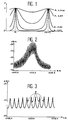
- la figure 1 montre le facteur de transmission d'un résonateur de FABRY-PEROT en fonction du coefficient de réflexion ;FIG. 1 shows the transmission factor of a FABRY-PEROT resonator as a function of the reflection coefficient;
- la figure 2 montre le spectre d'un laser à semiconducteur à FABRY-PEROT à faces réfléchissantes ;FIG. 2 shows the spectrum of a FABRY-PEROT semiconductor laser with reflecting faces;
- la figure 3 montre le même spectre mais avec une face traitée par une couche anti-reflet ;Figure 3 shows the same spectrum but with one side treated with an anti-reflection layer;
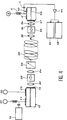
- la figure 4 illustre un montage permettant de tester le photorécepteur de l'invention ;Figure 4 illustrates an arrangement for testing the photoreceptor of the invention;
- la figure 5 montre la réponse en fréquence du photorécepteur de l'invention ;Figure 5 shows the frequency response of the photoreceptor of the invention;
- la figure 6 représente le taux d'erreurs en fonction de la puissance reçue.FIG. 6 represents the error rate as a function of the power received.
On voit, sur la figure 1, le taux de transmission T d'un résonateur FABRY-PEROT en fonction du coefficient de réflexion R de ses faces. Cette courbe est périodique en fréquence et définit différents modes longitudinaux m, m+1, etc...We see, in Figure 1, the transmission rate T of a FABRY-PEROT resonator as a function of the reflection coefficient R of its faces. This curve is periodic in frequency and defines different longitudinal modes m, m + 1, etc.
La résonance est d'autant moins surtendue que le coefficient de réflexion est plus faible. Ce coefficient est porté sur les diverses courbes représentées.The lower the resonance, the lower the reflection coefficient. This coefficient is plotted on the various curves represented.
Sur la figure 2, on voit le spectre d'un laser à semiconducteur utilisant un résonateur de FABRY-PEROT classique. Sur l'axe des abscisses est portée la longueur d'onde (en l'occurrence de 1550,9 nm à 1600,9 nm. En ordonnées figure l'intensité exprimée en dBm (décibels rapportés à 1 milliwatt).In Figure 2, we see the spectrum of a semiconductor laser using a conventional FABRY-PEROT resonator. The wavelength is plotted on the abscissa axis (in this case from 1550.9 nm to 1600.9 nm. On the ordinate is the intensity expressed in dBm (decibels referred to 1 milliwatt).
Sur la figure 3 est représenté le spectre d'un laser utilisé comme photorécepteur conformément à l'invention. La face d'entrée du laser FABRY-PEROT a été recouverte par une couche anti-reflet qui a fait tomber le coefficient de réflexion de cette face par exemple à environ 10⁻⁵ (au lieu de 33% pour une face sans traitement). La plage de fréquence va de 1522,4 nm à 1532,4 nm. L'une quelconque des zones marquées Z, situées sur le flanc de ces pics, peut être utilisée pour faire de la démodulation de fréquence.In Figure 3 is shown the spectrum of a laser used as photoreceptor according to the invention. The entry face of the FABRY-PEROT laser has been covered by an anti-reflection layer which has caused the reflection coefficient of this face to drop to around 10⁻⁵ for example (instead of 33% for a face without treatment). The frequency range is from 1522.4 nm to 1532.4 nm. Any of the areas marked Z, located on the side of these peaks, can be used for frequency demodulation.
La figure 4 représente un banc permettant de tester le photorécepteur de l'invention. Tel que représenté ce banc comprend tout d'abord une source optique monofréquence accordable en longueur d'onde et modulée en fréquence. Cette source peut être un laser DFB (par exemple de structure "Buried Ridge Stripe") dont l'électrode d'alimentation a été séparée en deux électrodes E1 et E2 reliées à deux sources de courants S1 et S2. Un générateur de signaux 12 permet de moduler la fréquence de ce laser. La longueur de la cavité peut être de 425 µm, avec une face 14 traitée anti-reflet à 2%.Figure 4 shows a bench for testing the photoreceptor of the invention. As shown, this bench comprises first of all a single frequency optical source tunable in wavelength and frequency modulated. This source can be a DFB laser (for example of "Buried Ridge Stripe" structure) whose supply electrode has been separated into two electrodes E1 and E2 connected to two current sources S1 and S2. A
Le banc comprend encore des moyens optiques comme un objectif de microscope 20, pour collimater le faisceaux émis par le laser 10, un isolateur 22 (isolation de 38 dB à 1,52 µm), afin d'éliminer les réflexions qui perturberaient le fonctionnement du laser 10, un second objectif 24 pour coupler la lumière dans le coeur d'une fibre monomode et un atténuateur optique variable 26.The bench also includes optical means such as a
Ces moyens permettent d'injecter le faisceau modulé en fréquence dans une fibre optique 28.These means make it possible to inject the frequency modulated beam into an
Côté réception, on trouve encore divers moyens optiques comme un premier objectif de microscope 30, un isolateur 32, un second objectif de microscope 34 permettant d'injecter le faisceau optique 36 dans la couche active du photorécepteur.On the reception side, there are also various optical means such as a
Le photorécepteur, référencé 40, comprend une face avant 41 traitée par un revêtement antiréfléchissante et une face arrière réfléchissante, une couche active 43, une électrode E reliée à une source de polarisation S, des moyens pour prélever la variation de tension aux bornes de l'électrode E. Ces moyens peuvent être constitués par un té de polarisation avec un condensateur de couplage C relié à un amplificateur 44 (par exemple de 55 dB). L'amplificateur peut alimenter un analyseur de spectre 46 et un compteur d'erreurs 48.The photoreceptor, referenced 40, comprises a
La figure 5 montre la réponse en fréquence mesurée de 1 MHz à 2 GHz avec ce banc pour deux puissances optiques injectées, respectivement P₁=-30 dBm et P₂=-33 dBm. La modulation de courant appliqué sur l'électrode du laser DFB était égale à 4 mA crête-crête, conduisant à une excursion de fréquence de 2 GHz. Cette courbe de réponse en fréquence présente une partie relativement plate jusqu'à 2 GHz.Figure 5 shows the frequency response measured from 1 MHz to 2 GHz with this bench for two injected optical powers, respectively P₁ = -30 dBm and P₂ = -33 dBm. The current modulation applied to the DFB laser electrode was 4 mA peak-peak, resulting in a frequency excursion of 2 GHz. This frequency response curve has a relatively flat part up to 2 GHz.
La limitation du débit de transmission était imposée par la réponse en fréquence du laser DFB émetteur.The limitation of the transmission rate was imposed by the frequency response of the transmitting DFB laser.
Pour une transmission à 1,5 GBit/s, avec un code (2⁻¹⁵-1)NRZ (Non Retour à Zéro), la courbe du taux d'erreur BER en fonction de la puissance reçue P(dBm) est celle de la figure 6.For a transmission at 1.5 GBit / s, with a NRZ (No Return to Zero) code (2⁻¹⁵-1), the curve of the BER error rate as a function of the received power P (dBm) is that of Figure 6.
On remarque qu'un taux d'erreur égal à 10⁻⁹ est obtenu pour une sensibilité du système égale à -30 dBm.It is noted that an error rate equal to 10⁻⁹ is obtained for a sensitivity of the system equal to -30 dBm.
Claims (4)
Applications Claiming Priority (2)
| Application Number | Priority Date | Filing Date | Title |
|---|---|---|---|
| FR9204005 | 1992-04-02 | ||
| FR9204005A FR2689708B1 (en) | 1992-04-02 | 1992-04-02 | PHOTORECEPTOR FOR FREQUENCY MODULATED OPTICAL SIGNALS. |
Publications (1)
| Publication Number | Publication Date |
|---|---|
| EP0564355A1 true EP0564355A1 (en) | 1993-10-06 |
Family
ID=9428389
Family Applications (1)
| Application Number | Title | Priority Date | Filing Date |
|---|---|---|---|
| EP93400831A Withdrawn EP0564355A1 (en) | 1992-04-02 | 1993-03-31 | Photoreceiver for frequency-modulated optical signals |
Country Status (4)
| Country | Link |
|---|---|
| US (1) | US5404242A (en) |
| EP (1) | EP0564355A1 (en) |
| JP (1) | JPH0677900A (en) |
| FR (1) | FR2689708B1 (en) |
Cited By (2)
| Publication number | Priority date | Publication date | Assignee | Title |
|---|---|---|---|---|
| CN102723985A (en) * | 2012-06-27 | 2012-10-10 | 长春理工大学 | Bandwidth optimization and design method for optical frequency code chips of spectral amplitude encoding/decoding system |
| CN102829870A (en) * | 2012-09-05 | 2012-12-19 | 天津奇谱光电技术有限公司 | Spectrum analytical equipment |
Families Citing this family (2)
| Publication number | Priority date | Publication date | Assignee | Title |
|---|---|---|---|---|
| DE69533352T2 (en) * | 1994-05-24 | 2005-07-28 | Koninklijke Philips Electronics N.V. | OPTOELECTRONIC SEMICONDUCTOR DEVICE WITH LASER AND PHOTODIODE |
| GB2424649A (en) * | 2003-11-21 | 2006-10-04 | Sekisui Chemical Co Ltd | Positive photoresist and method for producing structure |
Citations (2)
| Publication number | Priority date | Publication date | Assignee | Title |
|---|---|---|---|---|
| GB2229880A (en) * | 1989-02-08 | 1990-10-03 | American Telephone & Telegraph | Tunable narrowband receiver utilizing distributed Bragg reflector laser structure |
| FR2652465A1 (en) * | 1989-09-27 | 1991-03-29 | France Etat | PHOTORECEPTOR FOR OPTICAL SIGNALS MODULES IN FREQUENCY. |
Family Cites Families (4)
| Publication number | Priority date | Publication date | Assignee | Title |
|---|---|---|---|---|
| US4730327A (en) * | 1985-12-16 | 1988-03-08 | Lytel Incorporated | Dual channel fabry-perot laser |
| US4861136A (en) * | 1987-07-15 | 1989-08-29 | American Telephone And Telegraph Company | Optical communication systems using fabry-perot cavities |
| US5027435A (en) * | 1987-07-15 | 1991-06-25 | At&T Bell Laboratories | Optical communication systems using Fabry-Perot cavities |
| FR2685590B1 (en) * | 1991-12-20 | 1995-01-13 | France Telecom | NON - SELECTIVE PHOTORECEPTOR FOR FREQUENCY MODULATED OPTICAL SIGNALS AND OPTICAL LINK USING THE SAME. |
-
1992
- 1992-04-02 FR FR9204005A patent/FR2689708B1/en not_active Expired - Fee Related
-
1993
- 1993-03-26 US US08/037,593 patent/US5404242A/en not_active Expired - Fee Related
- 1993-03-31 EP EP93400831A patent/EP0564355A1/en not_active Withdrawn
- 1993-04-02 JP JP5098318A patent/JPH0677900A/en not_active Withdrawn
Patent Citations (2)
| Publication number | Priority date | Publication date | Assignee | Title |
|---|---|---|---|---|
| GB2229880A (en) * | 1989-02-08 | 1990-10-03 | American Telephone & Telegraph | Tunable narrowband receiver utilizing distributed Bragg reflector laser structure |
| FR2652465A1 (en) * | 1989-09-27 | 1991-03-29 | France Etat | PHOTORECEPTOR FOR OPTICAL SIGNALS MODULES IN FREQUENCY. |
Non-Patent Citations (1)
| Title |
|---|
| ELECTRONICS LETTERS. vol. 27, no. 23, 7 Novembre 1991, STEVENAGE GB pages 2183 - 2185 P.POTTIER ET AL '1.5 Gbit/s Transmission System using all Optical Wavelength Convertor based on Tunable two-electrode DFB Laser' * |
Cited By (3)
| Publication number | Priority date | Publication date | Assignee | Title |
|---|---|---|---|---|
| CN102723985A (en) * | 2012-06-27 | 2012-10-10 | 长春理工大学 | Bandwidth optimization and design method for optical frequency code chips of spectral amplitude encoding/decoding system |
| CN102723985B (en) * | 2012-06-27 | 2014-12-10 | 长春理工大学 | Bandwidth optimization and design method for optical frequency code chips of spectral amplitude encoding/decoding system |
| CN102829870A (en) * | 2012-09-05 | 2012-12-19 | 天津奇谱光电技术有限公司 | Spectrum analytical equipment |
Also Published As
| Publication number | Publication date |
|---|---|
| JPH0677900A (en) | 1994-03-18 |
| FR2689708A1 (en) | 1993-10-08 |
| US5404242A (en) | 1995-04-04 |
| FR2689708B1 (en) | 1994-05-13 |
Similar Documents
| Publication | Publication Date | Title |
|---|---|---|
| FR2512298A1 (en) | SYSTEM AND METHOD FOR OPTICAL FREQUENCY MODULATION | |
| US6088147A (en) | Method and apparatus for transmitting signals in an optical fiber | |
| EP0616398A1 (en) | Method and device for generating optical pulses | |
| FR2772150A1 (en) | OPTICAL MODULATOR USING AN OPTICAL ISOLATOR AND TRANSMITTER INCLUDING THE SUSDIT | |
| EP0222810B1 (en) | Optical homodyne detection | |
| EP0231015B1 (en) | Coherent photonic telecommunication device | |
| CA2238923C (en) | Optical transmission system with dynamic compensation of transmitted power | |
| FR2739502A1 (en) | LIGHT AMPLIFIER | |
| Dong et al. | Directly reflectivity modulated laser | |
| EP0420742B1 (en) | Photoreceptor for frequency-modulated optical signals | |
| EP0071309B1 (en) | Device for coupling a sender and a radiation receiver to one end of an optical fibre | |
| EP0564355A1 (en) | Photoreceiver for frequency-modulated optical signals | |
| AU637073B2 (en) | Phase modulation | |
| FR2681953A1 (en) | FREQUENCY CORRELATOR. | |
| EP0643459A1 (en) | Method of transferring optical modulation simultaneously over a multitude of wavelengths | |
| Hammad et al. | Photonically integrated gain‐switched lasers for optical frequency comb generation | |
| EP0926502A2 (en) | Opto-electronic antenna test system | |
| EP0550309B1 (en) | Non-selective photoreceiver for frequency modulated optical signals and optical link using the photoreceiver | |
| EP0598387B1 (en) | Optical transmission line and distortion reduction technique | |
| Cartledge et al. | Influence of modulator chirp in assessing the performance implications of the group delay ripple of dispersion compensating fiber Bragg gratings | |
| EP0618654B1 (en) | Optical intensity modulator using a two-electrode DFB laser | |
| EP0643460B1 (en) | Method of tunable wavelength conversion of modulated light | |
| Binsma et al. | DFB lasers with integrated electroabsorption modulator | |
| JP2900529B2 (en) | Apparatus for measuring high frequency response characteristics of semiconductor laser | |
| Vodhanel | Optical sources for coherent optical fiber communication systems |
Legal Events
| Date | Code | Title | Description |
|---|---|---|---|
| PUAI | Public reference made under article 153(3) epc to a published international application that has entered the european phase |
Free format text: ORIGINAL CODE: 0009012 |
|
| AK | Designated contracting states |
Kind code of ref document: A1 Designated state(s): DE GB |
|
| 17P | Request for examination filed |
Effective date: 19940310 |
|
| GRAG | Despatch of communication of intention to grant |
Free format text: ORIGINAL CODE: EPIDOS AGRA |
|
| 17Q | First examination report despatched |
Effective date: 19970604 |
|
| GRAG | Despatch of communication of intention to grant |
Free format text: ORIGINAL CODE: EPIDOS AGRA |
|
| GRAH | Despatch of communication of intention to grant a patent |
Free format text: ORIGINAL CODE: EPIDOS IGRA |
|
| STAA | Information on the status of an ep patent application or granted ep patent |
Free format text: STATUS: THE APPLICATION IS DEEMED TO BE WITHDRAWN |
|
| 18D | Application deemed to be withdrawn |
Effective date: 19971230 |