EP0563737A1 - Multilens imaging apparatus with correction of misregistration - Google Patents
Multilens imaging apparatus with correction of misregistration Download PDFInfo
- Publication number
- EP0563737A1 EP0563737A1 EP93104677A EP93104677A EP0563737A1 EP 0563737 A1 EP0563737 A1 EP 0563737A1 EP 93104677 A EP93104677 A EP 93104677A EP 93104677 A EP93104677 A EP 93104677A EP 0563737 A1 EP0563737 A1 EP 0563737A1
- Authority
- EP
- European Patent Office
- Prior art keywords
- image
- imaging optical
- imaging
- optical systems
- images
- Prior art date
- Legal status (The legal status is an assumption and is not a legal conclusion. Google has not performed a legal analysis and makes no representation as to the accuracy of the status listed.)
- Granted
Links
Images


















Classifications
-
- G—PHYSICS
- G06—COMPUTING OR CALCULATING; COUNTING
- G06T—IMAGE DATA PROCESSING OR GENERATION, IN GENERAL
- G06T3/00—Geometric image transformations in the plane of the image
- G06T3/14—Transformations for image registration, e.g. adjusting or mapping for alignment of images
- G06T3/147—Transformations for image registration, e.g. adjusting or mapping for alignment of images using affine transformations
-
- H—ELECTRICITY
- H04—ELECTRIC COMMUNICATION TECHNIQUE
- H04N—PICTORIAL COMMUNICATION, e.g. TELEVISION
- H04N13/00—Stereoscopic video systems; Multi-view video systems; Details thereof
- H04N13/20—Image signal generators
- H04N13/204—Image signal generators using stereoscopic image cameras
- H04N13/239—Image signal generators using stereoscopic image cameras using two two-dimensional [2D] image sensors having a relative position equal to or related to the interocular distance
-
- H—ELECTRICITY
- H04—ELECTRIC COMMUNICATION TECHNIQUE
- H04N—PICTORIAL COMMUNICATION, e.g. TELEVISION
- H04N13/00—Stereoscopic video systems; Multi-view video systems; Details thereof
- H04N13/20—Image signal generators
- H04N13/204—Image signal generators using stereoscopic image cameras
- H04N13/246—Calibration of cameras
-
- H—ELECTRICITY
- H04—ELECTRIC COMMUNICATION TECHNIQUE
- H04N—PICTORIAL COMMUNICATION, e.g. TELEVISION
- H04N13/00—Stereoscopic video systems; Multi-view video systems; Details thereof
- H04N13/20—Image signal generators
- H04N13/296—Synchronisation thereof; Control thereof
-
- H—ELECTRICITY
- H04—ELECTRIC COMMUNICATION TECHNIQUE
- H04N—PICTORIAL COMMUNICATION, e.g. TELEVISION
- H04N3/00—Scanning details of television systems; Combination thereof with generation of supply voltages
- H04N3/10—Scanning details of television systems; Combination thereof with generation of supply voltages by means not exclusively optical-mechanical
- H04N3/16—Scanning details of television systems; Combination thereof with generation of supply voltages by means not exclusively optical-mechanical by deflecting electron beam in cathode-ray tube, e.g. scanning corrections
- H04N3/22—Circuits for controlling dimensions, shape or centering of picture on screen
- H04N3/23—Distortion correction, e.g. for pincushion distortion correction, S-correction
- H04N3/233—Distortion correction, e.g. for pincushion distortion correction, S-correction using active elements
- H04N3/2335—Distortion correction, e.g. for pincushion distortion correction, S-correction using active elements with calculating means
-
- G—PHYSICS
- G06—COMPUTING OR CALCULATING; COUNTING
- G06T—IMAGE DATA PROCESSING OR GENERATION, IN GENERAL
- G06T2207/00—Indexing scheme for image analysis or image enhancement
- G06T2207/10—Image acquisition modality
- G06T2207/10004—Still image; Photographic image
- G06T2207/10012—Stereo images
-
- H—ELECTRICITY
- H04—ELECTRIC COMMUNICATION TECHNIQUE
- H04N—PICTORIAL COMMUNICATION, e.g. TELEVISION
- H04N13/00—Stereoscopic video systems; Multi-view video systems; Details thereof
- H04N13/10—Processing, recording or transmission of stereoscopic or multi-view image signals
- H04N13/106—Processing image signals
- H04N13/111—Transformation of image signals corresponding to virtual viewpoints, e.g. spatial image interpolation
-
- H—ELECTRICITY
- H04—ELECTRIC COMMUNICATION TECHNIQUE
- H04N—PICTORIAL COMMUNICATION, e.g. TELEVISION
- H04N13/00—Stereoscopic video systems; Multi-view video systems; Details thereof
- H04N13/10—Processing, recording or transmission of stereoscopic or multi-view image signals
- H04N13/106—Processing image signals
- H04N13/111—Transformation of image signals corresponding to virtual viewpoints, e.g. spatial image interpolation
- H04N13/117—Transformation of image signals corresponding to virtual viewpoints, e.g. spatial image interpolation the virtual viewpoint locations being selected by the viewers or determined by viewer tracking
-
- H—ELECTRICITY
- H04—ELECTRIC COMMUNICATION TECHNIQUE
- H04N—PICTORIAL COMMUNICATION, e.g. TELEVISION
- H04N13/00—Stereoscopic video systems; Multi-view video systems; Details thereof
- H04N13/10—Processing, recording or transmission of stereoscopic or multi-view image signals
- H04N13/189—Recording image signals; Reproducing recorded image signals
-
- H—ELECTRICITY
- H04—ELECTRIC COMMUNICATION TECHNIQUE
- H04N—PICTORIAL COMMUNICATION, e.g. TELEVISION
- H04N13/00—Stereoscopic video systems; Multi-view video systems; Details thereof
- H04N13/10—Processing, recording or transmission of stereoscopic or multi-view image signals
- H04N13/194—Transmission of image signals
-
- H—ELECTRICITY
- H04—ELECTRIC COMMUNICATION TECHNIQUE
- H04N—PICTORIAL COMMUNICATION, e.g. TELEVISION
- H04N13/00—Stereoscopic video systems; Multi-view video systems; Details thereof
- H04N13/20—Image signal generators
- H04N13/257—Colour aspects
-
- H—ELECTRICITY
- H04—ELECTRIC COMMUNICATION TECHNIQUE
- H04N—PICTORIAL COMMUNICATION, e.g. TELEVISION
- H04N13/00—Stereoscopic video systems; Multi-view video systems; Details thereof
- H04N13/20—Image signal generators
- H04N13/293—Generating mixed stereoscopic images; Generating mixed monoscopic and stereoscopic images, e.g. a stereoscopic image overlay window on a monoscopic image background
-
- H—ELECTRICITY
- H04—ELECTRIC COMMUNICATION TECHNIQUE
- H04N—PICTORIAL COMMUNICATION, e.g. TELEVISION
- H04N13/00—Stereoscopic video systems; Multi-view video systems; Details thereof
- H04N13/30—Image reproducers
-
- H—ELECTRICITY
- H04—ELECTRIC COMMUNICATION TECHNIQUE
- H04N—PICTORIAL COMMUNICATION, e.g. TELEVISION
- H04N13/00—Stereoscopic video systems; Multi-view video systems; Details thereof
- H04N2013/0074—Stereoscopic image analysis
- H04N2013/0081—Depth or disparity estimation from stereoscopic image signals
-
- H—ELECTRICITY
- H04—ELECTRIC COMMUNICATION TECHNIQUE
- H04N—PICTORIAL COMMUNICATION, e.g. TELEVISION
- H04N13/00—Stereoscopic video systems; Multi-view video systems; Details thereof
- H04N2013/0074—Stereoscopic image analysis
- H04N2013/0088—Synthesising a monoscopic image signal from stereoscopic images, e.g. synthesising a panoramic or high resolution monoscopic image
Definitions
- the present invention relates to a multi-lens imaging apparatus and, more particularly, to a multi-lens imaging apparatus which obtains a single high-fine image by synthesizing a plurality of images obtained by picking up a common object image using a plurality of imaging systems and to an apparatus which can provide a image having a different aspect ratio from that of a image obtained by a single imaging apparatus, for example, a panoramic image, by synthesizing a plurality of images obtained using a plurality of imaging optical systems.
- right and left side imaging systems 110 R and 110 L are prepared, and pick up an image of an object 101 by shifting their sampling points by a 1/2 spatial phase pitch.
- a right side image I R obtained by the right side imaging system 110 R and a left side image I L obtained by the left side imaging system 110 L are synthesized by a microprocessor (to be referred to as a "CPU” hereinafter) 120, thereby obtaining a single high-fine output image I OUT as compared to a image obtained when the image of the object 101 is picked up by a single imaging system.
- a microprocessor to be referred to as a "CPU” hereinafter
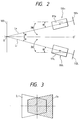
- Fig. 2 is an explanatory view for explaining a basic arrangement of the right and left side imaging systems 110 R and 110 L shown in Fig. 1.
- Optical axes L R and L L of the right and left imaging systems 110 R and 110 L cross almost at a point O on an object surface 102, and these systems are arranged at positions axially symmetrical about a normal O-O' to the object surface 102.
- ⁇ the angle formed between each of the optical axes L R and L L and the normal O-O' to the object surface 102 (to be referred to as an "inclination angle" hereinafter) is represented by ⁇ , 2 ⁇ is defined as the convergence angle.
- the convergence angle 2 ⁇ is changed by rotating each of the right and left side imaging systems 110 R and 110 L about an X mark shown in Fig. 2 in accordance with the change in object distance, thus performing an imaging operation.
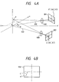
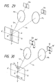
- FIG. 4A shows the outline of mis-registration in a multi-lens imaging system.
- the system shown in Fig. 4A includes imaging optical systems (lenses) 910 and 920, and image sensors 911 and 921.
- the imaging optical systems 910 and 920 have optical axes 912 and 922, respectively.
- an object image is picked up while the optical axes 912 and 922 are inclined through ⁇ in the x-z plane with respect to a central axis O-O', an arbitrary object point on an object surface is represented by P.
- an apparatus comprising detection means for detecting a mis-registration amount between imaging systems, and means for controlling at least a mechanism system or an image process system, so that the mis-registration amount detected by the detection means becomes equal to or smaller than a predetermined value, whereby images obtained from the imaging systems are synthesized while being registered with each other.
- an apparatus comprising means for detecting imaging conditions of a plurality of imaging systems, means for detecting position information of an object from image signals output from the imaging systems, and means for synthesizing images output from the imaging systems on the basis of the imaging conditions and the position information.
- the mis-registration amount of overlapping images may be partially detected.
- means for setting a convergence angle of imaging systems to be a predetermined value may be arranged so as to change the aspect ratio of an image.
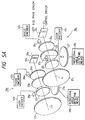
- Figs. 5A and 5B show an arrangement of a multi-lens imaging apparatus according to an embodiment of the present invention.
- the multi-lens imaging apparatus of this embodiment obtains a single high-fine image by synthesizing two images obtained by picking up an image of a common object using two imaging systems (right and left side imaging systems 10 R and 10 L )
- the left side imaging system 10 L includes a left side imaging optical system 11 L (see Fig. 8), a left side image sensor 12 L comprising a camera tube, and a camera tube electron beam scanning locus control driver 31 L for controlling the locus of scanning of the electron beam emitted from the camera tube constituting the left side image sensor 12 L .
- the left side imaging optical system 11 L includes lens groups 21 L to 24 L including a zoom lens group 22 L and a focus lens group 24 L , a zoom motor 25 L as a driving system for driving the zoom lens group 22 L , a focus motor 26 L as a driving system for driving the focus lens group 24 L , a mechanism system (not shown) and a driving system (convergence angle motor 27 L ) for integrally rotating the left side imaging optical system 11 L and the left side image sensor 12 L in a plane including an optical axis L L , and a rotational angle detecting means 28 L for detecting the rotational angle of the convergence angle motor 27 L .
- rotational angle detecting means 28 L for example, an externally attached member such as a rotary encoder may be used, or a means such as a pulse motor for detecting the rotational angle by the driving system itself according to a driving method may be used.
- the right side imaging system 10 R has the same arrangement as that of the left side imaging system 10 L .
- a focal length f of the left side imaging optical system 11 L always coincides with a focal length f of the right side imaging optical system 11 R
- an image formation magnification ⁇ of the left side imaging optical system 11 L always coincides with an image formation magnification ⁇ of the right side imaging optical system 11 R .
- a keystone distortion correction signal generation portion 32 L shown at the left side in Fig. 5B can calculate the focal length f of the left side imaging optical system 11 L on the basis of a signal from the zoom encoder 41 L
- a keystone distortion correction signal generation portion 32 R shown at the right side in Fig. 5B can calculate the focal length f of the right side imaging optical system 11 R on the basis of a signal from the zoom encoder 41 R
- the keystone distortion correction signal generation portion 32 L can calculate an object distance to the left side imaging optical system 11 L on the basis of a signal from the focus encoder 42 L ,it can calculate the image formation magnification ⁇ of the left side imaging optical system 11 L .
- the keystone distortion correction signal generation portion 32 R can calculate the image formation magnification ⁇ of the right side imaging optical system 11 R on the basis of a signal from the focus encoder 42 R . Furthermore, the keystone distortion correction signal generation portions 32 R and 32 L can calculate inclination angles ⁇ on the basis of signals from the corresponding rotational angle detecting means 28 R and 28 L .
- the multi-lens imaging apparatus of this embodiment further includes the keystone distortion correction signal generation portion 32 L for generating a keystone distortion correction signal on the basis of the output signals from the rotational angle detecting means 28 L , the zoom encoder 41 L , and the focus encoder 42 L of the left side imaging optical system 11 L , and outputting the keystone distortion correction signal to the camera tube electron beam scanning locus control driver 31 L , the keystone distortion correction signal generation portion 32 R for generating a keystone distortion correction signal on the basis of the output signals from the rotational angle detecting means 28 R , the zoom encoder 41 R , and the focus encoder 42 R of the right side imaging optical system 11 R , and outputting the keystone distortion correction signal to a camera tube electron beam scanning locus control driver 31 R , and a synthesizing process portion 38 for forming a single high-fine image by synthesizing a right side image I R sent from a right side image sensor 12 R and a left side image I L sent from the left
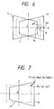
- a point P1 on the left side image I R corresponding to the point P0 is deviated rightward in Fig. 7 by a horizontal deviation amount ⁇ y0 ⁇ and is deviated upward in Fig. 7 by a vertical deviation amount ⁇ z0' if the coordinates of the point P0 are represented by (y0 ⁇ , z0'), and the coordinates of the point P1 are represented by (y0 ⁇ + ⁇ y0', z0'+ ⁇ z0').
- the horizontal and vertical deviation amounts ⁇ y0 ⁇ and ⁇ z0' can be calculated from the focal length f and the image formation magnification ⁇ of the right side imaging optical system 11 R and the inclination angle ⁇ of the right side imaging system 10 R . This principle will be described in more detail below with reference to Fig. 8.
- a point P0 on the object surface 2 and a point P1 on the conjugate object surface 3, which satisfy OP0 OP1 , will be examined below.
- image heights on the right side image sensor 12 R with respect to the object heights y0 and y1 are respectively represented by y0' and y1'
- the synthesizing process portion 38 synthesizes the right and left side images I R and I L without executing the keystone distortion correction of the right and left side images I R and I L , and outputs the synthesized image to the high fine monitor 40.
- the right and left side imaging systems 10 R and 10 L are inclined in opposite directions by the convergence angle motors 27 R and 27 L , so that the right and left side imaging systems 10 R and 10 L are directed toward the object surface 2. Thereafter, the inclination angles ⁇ of the right and left side imaging systems 10 R and 10 L are controlled by the convergence angle motors 27 R and 27 L , so that the sampling points on the optical axis L L of the left side imaging system 10 L are shifted by a 1/2 spatial phase pitch from those on the optical axis L R of the right side imaging system 10 R .
- the magnification setting operations and focusing operations of the right and left side imaging optical systems 11 R and 11 L are performed using the zoom motors 25 R and 25 L and the focus motors 26 R and 26 L .
- the keystone distortion correction signal generation portion 32 L of the left side imaging optical system 11 L calculates the horizontal and vertical deviation amounts ⁇ y0' and ⁇ z0' of each point on the left side image I L obtained by the left side image sensor 12 L using the output signals from the rotational angle detecting means 28 L and the focus encoder 42 L and the zoom encoder 41 L from equations (7) to (9) described above, generates a keystone distortion correction signal for correcting the keystone distortion generated in the left side image I L , and outputs the signal to the camera tube electron beam scanning locus control driver 31 L of the left side imaging optical system 11 L .
- the distance S0' is calculated from equation (9).
- the distance S0' may be calculated from the output signal from the focus encoder 42 L .
- the keystone distortion correction signal generation portion 32 R of the right side imaging optical system 11 R operates in the same manner as described above.
- the camera tube electron beam scanning locus control driver 31 L of the left side imaging optical system 11 L changes the scanning locus of the electron beam emitted from the camera tube constituting the left side image sensor 12 L on the basis of the keystone distortion correction signal sent from the keystone distortion correction signal generation portion 32 L , thereby correcting the keystone distortion generated in the left side image I L .
- the camera tube electron beam scanning locus control driver 31 L of the left side imaging optical system 11 L changes the scanning locus of the electron beam by controlling a deflection circuit of the camera tube constituting the left side image sensor 12 L on the basis of the keystone distortion correction signal sent from the keystone distortion correction signal generation portion 32 L , thereby scanning the left side image I L along a point A1 ⁇ a point B1, a point A2 ⁇ a point B2, a point A3 ⁇ a point B3, and a point A4 ⁇ a point B4, as indicated by the left-hand side figure in Fig. 9.
- the left side image I L output from the camera tube constituting the left side image sensor 12 L is converted into the required image I, which is scanned along a point a1 ⁇ a point b1, a point a2 ⁇ a point b2, a point a3 ⁇ a point b3, and a point a4 ⁇ a point b4, as indicated by the right-hand side figure in Fig. 9, and the converted image is input to the synthesizing process portion 38.
- the right and left imaging optical systems 11 R and 11 L may be constituted using zoom lenses or fixed focal point lenses.
- Fig. 10 is a perspective view showing the arrangement of the right and left side imaging systems 10 R and 10 L in a multi-lens imaging apparatus according to another embodiment of the present invention
- Fig. 11 is a block diagram for explaining operations of correction conversion portions 52 R and 52 L .
- the multi-lens imaging apparatus of this embodiment has the following differences from the multi-lens imaging apparatus of the embodiment shown in Figs. 5A and 5B.
- the right and left side imaging systems 10 R and 10 L are inclined by the convergence angle motors 27 R and 27 L in opposite directions, so that the right and left side imaging systems 10 R and 10 L are directed toward the object surface 2. Thereafter, the inclination angles ⁇ of the right and left side imaging systems 10 R and 10 L are controlled by the convergence angle motors 27 R and 27 L , so that the sampling points on the optical axis L L of the left side imaging system 10 L are shifted by a 1/2 spatial phase pitch from those on the optical axis L R of the right side imaging system 10 R .
- the magnification setting operations and focusing operations of the right and left side imaging optical systems 11 R and 11 L are performed using the zoom motors 25 R and 25 L and the focus motors 26 R and 26 L .
- the keystone distortion correction signal generation portion 32 L of the left side imaging optical system 11 L calculates the horizontal and vertical deviation amounts ⁇ y0' and ⁇ z0' of each point on the left side image I L obtained by the left side image sensor 12 L using the output signals from the rotational angle detecting means 28 L and the focus encoder 42 L and the zoom encoder 41 L from equations (7) to (9) described above, generates a keystone distortion correction signal for correcting the keystone distortion generated in the left side image I L , and outputs the signal to the correction conversion portion 52 L .
- the correction conversion portion 52 L converts the coordinate of the left side image data of the left side image I L read out from the left side image memory 51 L so as to cancel the horizontal and vertical deviation amounts ⁇ y0' and ⁇ z0' on the basis of the keystone distortion correction signal sent from the keystone distortion correction signal generation portion 32 L , thereby correcting the keystone distortion generated in the left side image I L .
- the distance S0' is calculated from equation (9).
- the distance S0' may be calculated from the output signal from the focus encoder 42 L .
- the keystone distortion correction signal generation portion 32 R and the correction conversion portion 52 R of the right side imaging optical system 11 R perform the same operation as described above.
- the synthesizing process portion 38 synthesizes the right and left side image data of the right and left side images I R and I L , which are respectively sent from the correction conversion portions 52 R and 52 L , and in which the keystone distortions are corrected, so that a single high-fine synthesized image can be displayed on the high fine monitor 40.
- the output signal from the correction conversion portion 52 L is supplied to the synthesizing process portion 38.
- the output signal from the correction conversion portion 52 L may be stored again in the left side image memory 51 L , and thereafter, the data may be supplied from the left side image memory 51 L to the synthesizing process portion 38. The same applies to the output signal from the other correction conversion portion 52 R .
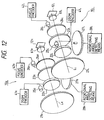
- Fig. 12 is a perspective view showing an arrangement of the right and left imaging systems 10 R and 10 L in a multi-lens imaging apparatus according to still another embodiment of the present invention
- Fig. 13 is a block diagram for explaining operations of correction optical systems 61 R and 61 L .
- lenses constituting correction optical systems 61 R and 61 L are decentered in the vertical direction with respect to the optical axes L R and L L so as to generate distortions, thereby correcting keystone distortions generated in the right and left side images I R and I L obtained by the right and left side image sensors 12 R and 12 L .
- the arrangement of the multi-lens imaging apparatus is substantially the same as that of the multi-lens imaging apparatus of the embodiment shown in Figs.
- the apparatus of this embodiment has the correction optical system 61 L arranged between the left side imaging optical system 11 L and the left side image sensor 12 L , and the correction optical system 61 R arranged between the right side imaging optical system 11 R and the right side image sensor 12 R , in place of the correction conversion portions 52 L and 52 R .
- the right and left side images I R and I L are synthesized by the synthesizing process portion 38 without executing keystone distortion correction of the right and left side images I R and I L , and the synthesized image is output to the high fine monitor 40.
- the right and left side imaging systems 10 R and 10 L are inclined by the convergence angle motors 27 R and 27 L in opposite directions, so that the right and left side imaging systems 10 R and 10 L are directed toward the object surface 2. Thereafter, the inclination angles ⁇ of the right and left side imaging systems 10 R and 10 L are controlled by the convergence angle motors 27 R and 27 L , so that the sampling points on the optical axis L L of the left side imaging system 10 L are shifted by a 1/2 spatial phase pitch from those on the optical axis L R of the right side imaging system 10 R .
- the magnification setting operations and focusing operations of the right and left side imaging optical systems 11 R and 11 L are performed using the zoom motors 25 R and 25 L and the focus motors 26 R and 26 L .
- the keystone distortion correction signal generation portion 32 L of the left side imaging optical system 11 L calculates the horizontal and vertical deviation amounts ⁇ y0 ⁇ and ⁇ z0 ⁇ of each point on the left side image I L obtained by the left side image sensor 12 L using the output signals from the rotational angle detecting means 28 L and the focus encoder 42, and the zoom encoder 41 L from equations (7) to (9) described above, generates a keystone distortion correction signal for correcting the keystone distortion generated in the left side image I L , and outputs the signal to the correction optical system 61 L of the left side imaging optical system 11 L .
- the correction optical system 61 L of the left side imaging optical system 11 L decenters at least one of lenses constituting the correction optical system 61 L in the vertical direction with respect to the optical axis L L on the basis of the keystone distortion correction signal sent from the keystone distortion correction signal generation portion 32 L so as to generate a distortion, thereby correcting the keystone distortion generated in the left side image I L .
- the distance S0' is calculated from equation (9).
- the distance S0' may be calculated from the output signal from the focus encoder 42 L .
- the keystone distortion correction signal generation portion 32 R and the correction optical system 61 R of the right side imaging optical system 11 R perform the same operations as described above.
- the object surface 2 is inclined through the inclination angle ⁇ with respect to the optical axis L R , and its image is formed on the right side image sensor 12 R .
- S1 the distance from the object surface 2 to the right side imaging optical system 11 R
- S1' the distance from the right side imaging optical system 11 R to the image surface of the right side image sensor 12 R
- a point O on the object surface 2 is defined as an intersection between the optical axis L R and the object surface 2
- an image formation magnification ⁇ H at a height H of the object surface 2 is expressed as follows by a paraxial calculation:
- Figs. 17A and 17B show a multi-lens imaging apparatus according to still another embodiment of the present invention.
- the multi-lens imaging apparatus of this embodiment obtains a single high-fine image by synthesizing two images obtained by picking up an image of a common object using two imaging systems (right and left side imaging systems 10 R and 10 L ).
- the left side imaging system 10 L includes lens groups 21 L to 24 L including a zoom lens group 22 L and a focus lens group 24 L , a zoom motor 25 L as a driving system for driving the zoom lens group 22 L , a focus motor 26 L as a driving system for driving the focus lens group 24 L , a mechanism system (not shown) and a driving system (convergence angle motor 27 L ) for integrally rotating the left side imaging optical system 11 L and a left side image sensor 12 L in a plane including an optical axis L L , and a rotational angle detecting means 28 L for detecting the rotational angle of the convergence angle motor 27 L , which constitute a left side imaging optical system 11 L .
- rotational angle detecting means 28 L for example, an externally attached member such as a rotary encoder may be used, or a means such as a pulse motor for detecting the rotational angle by the driving system itself according to a driving method may be used.
- the right side imaging system 10 R has the same arrangement as that of the left side imaging system 10 L .
- a focal length f of the left side imaging optical system 11 L always coincides with a focal length f of the right side imaging optical system 11 R
- an image formation magnification ⁇ of the left side imaging optical system 11 L always coincides with an image formation magnification ⁇ of the right side imaging optical system 11 R .
- a calculation control portion 71 shown in Fig. 17B can calculate the focal length f of the left side imaging optical system 11 L on the basis of a signal from the zoom encoder 41 L , and can calculate the focal length f of the right side imaging optical system 11 R on the basis of a signal from the zoom encoder 41 R . Also, since the calculation control portion 71 can calculate an object distance to the left side imaging optical system 11 L on the basis of a signal from the focus encoder 42 L , it can calculate the image formation magnification ⁇ of the left side imaging optical system 11 L , and similarly, it can calculate the image formation magnification ⁇ of the right side imaging optical system 11 R on the basis of a signal from the focus encoder 42 R . Furthermore, the calculation control portion 71 can calculate inclination angles ⁇ from the signals output from the rotational angle detecting means 28 R and 28 L .
- the output signals from the zoom encoders 41 R and 41 L and the focus encoders 42 R and 42 L are input to the calculation control portion 71, as shown in Fig. 17B.
- Left side image data of a left side image I L output from the left side image sensor 12 L is stored in a left side image memory 72 L
- right side image data of a right side image I R output from the right side image sensor 12 R is stored in a right side image memory 72 R .
- the keystone distortion conversion portion 73 calculates horizontal and vertical deviation amounts ⁇ y0' and ⁇ z0' of predetermined several image points from equations (7) and (8) described above using the left side image data read out from the left side image memory 72 L , the right side image data read out from the right side image memory 72 R , and the distances S0' sent from the calculation control portion 71.
- the keystone distortion conversion portion 73 shifts the coordinates of the image points in the right and left side image memories 72 R and 72 L by the calculated horizontal and vertical deviation amounts ⁇ y0' and ⁇ z0', and writes the shifted right and left side image data in the second right and left side image memories 74 R and 74 L , respectively.
- the subtraction process circuit 75 reads out the coordinate-shifted right and left side image data respectively from the second right and left side image memories 74 R and 74 L , and calculates a sum (to be referred to as an "image difference" hereinafter) ⁇ S1 of the absolute values of differences of these data.
- the keystone distortion conversion portion 73 calculates the horizontal and vertical deviation amounts ⁇ y0 ⁇ and ⁇ z0 ⁇ of all image points of the left side image data from equations (7) and (8) using the inclination angle ⁇ 0 (conversion variable) at which the image difference ⁇ s assumes a minimum value, thereafter, shifts the coordinates of all the image points of the left side image data by the calculated horizontal and vertical deviation amounts ⁇ y0 ⁇ and ⁇ z0 ⁇ , and writes the shifted left side image data in the second left side image memory 74 L .
- the left side image data in which the keystone distortion is corrected is written in the second left side image memory 74 L .
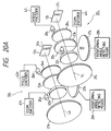
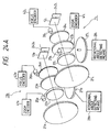
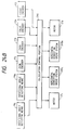
- Figs. 20A and 20B show a multi-lens imaging apparatus according to still another embodiment of the present invention.
- the arrangement of the multi-lens imaging apparatus of this embodiment is substantially the same as that of the multi-lens imaging apparatus of the embodiment shown in Figs. 17A and 17B, except that the right and left image sensors 12 R and 12 L comprise camera tubes, and the keystone distortion conversion portion 73 controls camera tube electron beam scanning locus drivers 31 R and 31 L according to the calculated horizontal and vertical deviation amounts ⁇ y0' and ⁇ z0'.
- Figs. 21A to 21C show a multi-lens imaging apparatus according to still another embodiment of the present invention
- Fig. 22 shows a basic arrangement of imaging systems in the multi-lens imaging apparatus of the embodiment shown in Figs. 21A to 21C.
- the multi-lens imaging apparatus of this embodiment obtains a single high-fine image by synthesizing two images obtained by picking up an image of a common object using two sets of imaging systems (right and left side imaging systems 10 R and 10 L ) .
- the left side imaging system 10 L is constituted by a left side imaging optical system 11 L and a left side image sensor 12 L
- the right side imaging system 10 R is constituted by a right side imaging optical system 11 R and a right side image sensor 12 R
- the right and left side imaging optical systems 11 R and 11 L have equivalent specifications, and each comprises a zoom lens.
- the right and left side image sensors 12 R and 12 L have equivalent specifications, and each comprises a camera tube such as a saticon or a solid-state imaging element such as a CCD.
- Optical axes L R and L L of the right and left imaging systems 10 R and 10 L cross almost at a point O on an object surface 2, and these systems are arranged at positions axially symmetrical about a normal O-O' to the object surface 2.
- the convergence angle 2 ⁇ is changed by rotating each of the right and left side imaging systems 10 R and 10 L about an X mark shown in Fig. 22 in accordance with the change in object distance, thus performing an imaging operation.
- the left side imaging system 10 L includes lens groups 21 L to 24 L including a zoom lens group 22 L and a focus lens group 24 L , a zoom motor 25 L as a driving system for driving the zoom lens group 22 L , a focus motor 26 L as a driving system for driving the focus lens group 24 L , a mechanism system (not shown) and a driving system (convergence angle motor 27 L ) for integrally rotating the left side imaging optical system 11 L and a left side image sensor 12 L in a plane including an optical axis L L , and a rotational angle detecting means 28 L for detecting the rotational angle of the convergence angle motor 27 L , which constitute a left side imaging optical system 11 L .
- rotational angle detecting means 28 L for example, an externally attached member such as a rotary encoder may be used, or a means such as a pulse motor for detecting the rotational angle by the driving system itself according to a driving method may be used.
- the right side imaging system 10 R has the same arrangement as that of the left side imaging system 10 L .
- the rotational angle detecting means 28 L detects the angular deviation ⁇ L with respect to an angle ⁇ (see Fig. 22) formed between the optical axis L L of the left side imaging system 10 L and the normal O-O' to the object surface 2
- the rotational angle detecting means 28 R detects the angular deviation ⁇ R with respect to an angle ⁇ formed between the optical axis R R of the right side imaging system 10 R and the normal O-O' to the object surface 2.
- the angular deviations ⁇ R and ⁇ L output from the rotational angle detecting means 28 R and 28 L are supplied to a control portion 231.
- the control portion 231 supplies a correction signal - ⁇ L to the convergence angle motor 27 L of the left side imaging system 10 L as a control target value, and supplies a correction signal - ⁇ R to the convergence angle motor 27 R of the right side imaging system 10 R as a control target value, as shown in Fig. 21B.
- the mis-registration amount ⁇ a of the image obtained by each of the right and left imaging systems 10 R and 10 L can be corrected to be equal to or smaller than the allowable value ⁇ a0.
- a image signal output from the left side image sensor 12 L is stored in a left side image memory 232 L
- a image signal output from the right side image sensor 12 R is stored in a right side image memory 232 R , as shown in Fig. 21C.
- these images are synthesized by a synthesizing process circuit 233, and a synthesized image signal is output.
- the multi-lens imaging apparatus of this embodiment can synthesize images obtained by the right and left imaging systems 10 R and 10 L while registering the two images, if, for example, the convergence angle is controlled in advance so that the relative spatial phase between the right and left side image sensors 12 R and 12 L is shifted by a 1/2 pitch when the sampling points of the right and left image side sensors 12 R and 12 L are imaginarily projected onto an object, the synthesizing process circuit 233 can obtain a single high fine image.
- a solid state imaging element when a solid state imaging element is used as each of the right and left side image sensors 12 R and 12 L , either a single-sensor type element or two- or three-sensor type element via a color separation system may be used.
- a camera tube is used as each of the right and left side image sensors 12 R and 12 L , either a single-tube type element or two- or three-tube type element via a color separation system may be used.
- the control portion 231 may supply a correction signal -( ⁇ L + ⁇ R ) to one of the two convergence angle motors 27 R and 27 L as a control target value in place of respectively supplying the correction signals - ⁇ R and - ⁇ L to the two convergence angle motors 27 R and 27 L as control target values.
- Figs. 24A and 24B show a multi-lens imaging apparatus according to still another embodiment of the present invention.
- the correction signals - ⁇ R and - ⁇ L output from the control portion 231 also take small values (e.g., on the order of several seconds), and it becomes difficult to obtain angular response performance necessary for correction under the influence of, e.g., non-sensitive bands of the convergence angle motors 27 R and 27 L .
- the image mis-registration amount ⁇ a given by equation (18) is calculated, and is corrected by means other than the convergence angle motors 27 R and 27 L , thereby solving the above-mentioned problem.
- the apparatus of this embodiment has the following differences from the multi-lens imaging apparatus of the embodiment shown in Figs. 21A to 21C.
- the focal length f and the image formation magnification ⁇ are caused to always coincide with each other.
- the focal length f and the image formation magnification ⁇ are similarly caused to always coincide with each other.
- the focal lengths f and the image formation magnifications ⁇ of the right and left side imaging optical systems 11 R and 11 L can be obtained from the output signals from the zoom encoders 41 R and 41 L , and the object distances S0 with respect to the right and left side imaging optical systems 11 R and 11 L can be obtained from the output signals from the focus encoders 42 R and 42 L .
- the output signals from the zoom encoders 41 R and 41 L and the focus encoders 42 R and 42 L are input to the calculation control portion 244, and the calculation control portion 244 calculates equation (18) described above, thus obtaining the mis-registration amounts ⁇ a0 of images.
- the calculation control portion 244 controls the horizontal direction drive systems 243 R and 243 L to move the right and left side image sensors 12 R and 12 L in the horizontal direction according to the calculated mis-registration amounts ⁇ a0 of the images, thereby correcting the mis-registration amounts ⁇ a of the images to be equal to or smaller than the allowable value ⁇ a0.
- each of the zoom encoders 41 R and 41 L and the focus encoders 42 R and 42 L for example, an externally attached member such as a potentiometer may be used, or a means such as a pulse motor for detecting the rotational angle by the driving system itself according to a driving method may be used.
- each of the horizontal direction drive systems 243 R and 243 L may comprise, e.g., a piezo element or piezoelectric bimorph.
- encoders for respectively detecting inclination angles (elevation angles) ⁇ 1, in the vertical direction, of the right and left side imaging systems 10 R and 10 L , and vertical direction drive systems for respectively moving the right and left side image sensors 12 R and 12 L in the vertical direction may be separately arranged.
- mis-registration amounts ⁇ b, in the vertical direction, of images obtained by the right and left imaging systems 10 R and 10 L can be similarly corrected to be equal to or smaller than an allowable value ⁇ b0.
- the mis-registration amounts ⁇ b, in the vertical direction, of images may be corrected upon combination of coarse adjustment attained by the convergence angle motors 27 R and 27 L in the multi-lens imaging apparatus of the embodiment shown in Figs. 21A to 21C, and fine adjustment attained by the horizontal direction drive systems 243 R and 243 L in the multi-lens imaging apparatus of this embodiment:
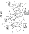
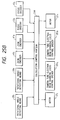
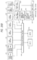
- Figs. 25A and 25B show a multi-lens imaging apparatus according to still another embodiment of the present invention.
- the right and left side image sensors 12 R and 12 L respectively comprise camera tubes, and the arrangement of the apparatus of this embodiment is substantially the same as that of the multi-lens imaging apparatus of the embodiment shown in Figs. 24A and 24B, except that camera tube electron beam scanning locus control drivers 251 R and 251 L are used in place of the horizontal direction drive systems 243 R and 243 L .
- the scanning loci of the electron beams by the camera tubes are controlled by the camera tube electron beam scanning locus control drivers 251 R and 251 L in accordance with the mis-registration amounts ⁇ a obtained by equation (18) above, thereby registering the images expressed by the video signals output from the right and left side image sensors 12 R and 12 L .
- Figs. 26A and 26B show a multi-lens imaging apparatus according to still another embodiment of the present invention.
- the right and left side image sensors 12 R and 12 L respectively comprise solid-state imaging device, and the mis-registration amounts ⁇ a of images obtained by the right and left imaging systems 10 R and 10 L are corrected to be equal to or smaller than the allowable value ⁇ a0 without using the horizontal direction drive systems 243 R and 243 L shown in Fig. 24B.
- the apparatus of this embodiment has the following differences from the multi-lens imaging apparatus of the embodiment shown in Figs. 24A and 24B.
- the calculation control portion 244 receives the output signals from the rotational angle detecting means 28 R and 28 L , the zoom encoders 41 R and 41 L , and the focus encoders 42 R and 42 L , and calculates the mis-registration amounts ⁇ a and ⁇ b of images using equations (18) and (19).
- the correction conversion portion 261 converts the coordinates of image data output from the left side image memory 232 L in accordance with the mis-registration amount ⁇ a calculated by the calculation control portion 244, and writes the converted image data in the second left side image memory 262.
- the synthesizing process circuit 233 synthesizes the image data respectively output from the second left side image memory 262 and the right side image memory 232 R , a high-fine synthesized image signal can be obtained.
- correction conversion portion 261 and a second left side image memory may be arranged between the right side image memory 232R and the synthesizing process circuit 233 in place of the correction conversion portion 261 and the second left side image memory 262.
- the left side image memory 232 L and the second left side image memory 262 may be replaced with a common one. Furthermore, when the coordinates of image data output from the left side image memory 232 L are converted, an interpolation calculation process of image data may be performed as needed.
- the mis-registration amounts ⁇ a of images are calculated based on the output signals from the rotational angle detecting means 28 R and 28 L , the zoom encoders 41 R and 41 L , and the focus encoders 42 R and 42 L .
- the mis-registration amounts ⁇ a of images may be calculated from image signals output from the right and left imaging systems 10 R and 10L.
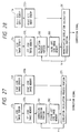
- Fig. 27 is a block diagram for explaining an operation of a correlation calculation process portion in a multi-lens imaging apparatus according to still another embodiment of the present invention.
- the multi-lens imaging apparatus of this embodiment has the following differences from the multi-lens imaging apparatus of the embodiment shown in Figs. 26A and 26B.
- the correction conversion portion 261 shifts the coordinates of image data output from the left side image memory 232 L in the horizontal and vertical directions by a predetermined shift amount X (e.g., by one pixel each in the horizontal and vertical directions), and writes the coordinate-shifted image data in the second left side image memory 262.
- the correlation calculation process portion 271 performs a correlation calculation between image data output from the second left side image memory 262 and image data output from the right side image memory 232 R to obtain a correlation value ⁇ s .
- the portion 271 calculates a new shift amount X so that the correlation value ⁇ s becomes equal to or smaller than the predetermined value, and outputs the calculated shift amount X to the correction conversion portion 261.
- the correction conversion portion 261 shifts the coordinates of image data output from the left side image memory 232 L in the horizontal and vertical directions by the new shift amount X, and writes the coordinate-shifted image data in the second left side image memory 262. Thereafter, the above-mentioned operations are repeated until the correlation value ⁇ s becomes equal to or smaller than the predetermined value.
- a synthesizing process circuit (not shown) synthesizes image data respectively output from the second left side image memory 262 and the right side image memory 232 R , thus obtaining a high-fine synthesized image signal.
- the correlation calculation may be performed using only image data at the central portion of a frame.
- a correlation calculation method a known matching method, gradient method, or the like may be used.
- the correlation calculation process portion 271 may calculate a correction signal corresponding to the finally obtained shift amount X0, and the correction control methods described in the embodiments shown in Figs. 21A to 25B, i.e., the following control methods may be executed:
- Fig. 28 is a block diagram for explaining an operation of a magnification correlation calculation process portion in a multi-lens imaging apparatus according to still another embodiment of the present invention.
- the multi-lens imaging apparatus of this embodiment has substantially the same arrangement as that of the multi-lens imaging apparatus of the embodiment shown in Fig. 27, except that the apparatus of this embodiment includes a magnification correlation calculation process portion 281, a calculation process portion 282, and a third left side image memory 283.
- the calculation process portion 282 converts the coordinates of image data output from the left side image memory 232 L by multiplying the coordinates with a constant k proportional to the distance from the center of the frame, and writes the coordinate-converted image data in the third left side image memory 283.
- the magnification correlation calculation process portion 281 executes a correlation calculation between image data output from the third left side image memory 283 and image data output from the right side image memory 232 R to obtain a correlation value ⁇ s .
- the portion 281 calculates a new constant k, so that the correlation value ⁇ s becomes equal to or smaller than the predetermined value, and outputs the constant to the calculation process portion 282.
- the calculation process portion 282 converts the coordinates of image data output from the left side image memory 232 L by multiplying the coordinates with the new constant k, and writes the coordinate-converted image data in the third left side image memory 283. Thereafter, the above-mentioned operations are repeated until the correlation value ⁇ s becomes equal to or smaller than the predetermined value.
- a synthesizing process circuit (not shown) synthesizes image data respectively output from the second left side image memory 262 and the right side image memory 232 thus obtaining a high-fine synthesized image signal from which the mis-registration amounts of images caused by a difference between the image formation magnifications of the right and left imaging optical systems 11 R and 11 L are corrected.
- the magnification correlation calculation process portion 281 may calculate a correction signal according to the finally obtained constant k0, and may execute the correction control methods described in the embodiments shown in Figs. 21A to 25B.
- the correlation calculation may be executed using only image signals in a hatched region (a region obtained by narrowing a horizontal process portion) having as its center a line Y-Y' passing through a point O on the object surface 2 and perpendicular to the plane including two optical axes L R and L L , as shown in Fig. 29. Since this region has symmetricity from the arrangement conditions of the right and left side imaging optical systems 11 R and 11 L , and suffers from a common image distortion, a difference between the image formation magnifications can be easily calculated.
- a positional deviation correlation in the vertical direction may be calculated by the method described in the embodiment shown in Figs. 26A and 26B using only image signals in two upper and lower hatched regions which have as their center a line Y-Y' passing through the point O on the object surface 2 and perpendicular to the plane including two optical axes L R and L L , and which are separated from the point O, as shown in Fig. 30.
- the final constant k0 is obtained as described above, and the following correction control can be made on the basis of this constant k0.
- Each of the multi-lens imaging apparatuses according to the above-mentioned embodiments of the present invention comprises two imaging systems.
- the present invention can also be applied to an apparatus using three or more imaging systems.
- An embodiment of an apparatus for displaying images while partially overlapping image fields using a plurality of imaging systems e.g., for obtaining a panoramic image or a 3D-2D mixed image is disclosed.
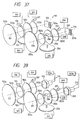
- Fig. 31 shows the basic arrangement of a panoramic multi-lens imaging system according to the present invention.
- the system includes a common object surface 1, and first and second imaging optical systems 102 and 202 having equivalent specifications, and normally comprising zoom lenses.
- the system also includes image sensors 103 and 203 similarly having equivalent specifications.
- Each of the image sensors 103 and 203 comprises a camera tube such as a saticon or a solid state imaging element such as a CCD.
- Optical axes 101 and 201 of these image sensors are arranged to be inclined through about ⁇ symmetrically about a normal 0-0' to the object surface 1 so as to satisfy a condition that image fields to be picked up by these sensors overlap each other by a predetermined amount. Note that 2 ⁇ will be referred to as the convergence angle, and is changed according to the image formation magnifications of the imaging optical systems (the object distances and the focal lengths of photographing lenses).
- Fig. 32 shows the detailed arrangement of the imaging optical systems and the image sensors.
- a support structure such as a lens barrel is not shown.
- the first and second imaging optical systems 102 and 202 are respectively constituted by lens groups 102a, 102b, 102c, and 102d, and lens groups 202a, 202b, 202c, and 202d.
- the lens groups 102b and 202b are zoom lens groups
- the lens groups 102d and 202d are focus lens groups.
- the zoom lens groups 102b and 202b are respectively driven by drive systems (zoom motors) 106 and 206, and similarly, the focus lens groups 102d and 202d are respectively driven by drive systems (focus motors) 107 and 207.
- Encoders (zoom encoders) 108 and 208 are provided to the zoom lens groups 102b and 202b of the imaging optical systems so as to obtain position information, in the optical axis direction, of the corresponding lens groups. Focal lengths f of the imaging optical systems 102 and 202 can be obtained based on signals output from the encoders 108 and 208. Note that the lens groups 102d and 202d also have a function of compensating for image surface movement upon movement of the zoom lens groups in addition to the focus function. Since the arrangement of the zoom lens is well known, a detailed description thereof will be omitted.
- Encoders (focus encoders) 109 and 209 are provided to the focus lens groups 102d and 202d of the imaging optical systems so as to obtain position information, in the optical axis direction, of the corresponding lens groups.
- These encoders may comprise, e.g., externally attached members such as potentiometers, or may comprise systems such as pulse motors for detecting the position information, in the optical axis direction, of the lens by the drive systems themselves according to their drive method.
- the system of this embodiment further includes mechanism systems (not shown) for integrally rotating the optical system 102 and the image sensor 103, and the optical system 202 and the image sensor 203 in opposite directions by the same amount in planes respectively including optical axes 101 and 201, and drive systems (convergence angle motors) 104 and 204 for attaining such rotations.
- the system also includes rotational angle information detecting means 105 and 205. These means may comprise, e.g., externally attached members such as rotary encoders, or may comprise systems such as pulse motors for detecting the position information, in the optical axis direction, of angle information by the drive systems themselves according to their drive method.
- Image memories 111 and 211 temporarily store signals of the overlapping portion of image signals 110 and 210. Assume that image data are mis-registered due to a deviation in convergence angle.
- a horizontal image shift process portion 20 shifts the coordinates of image data in the image memory 111 in the horizontal direction by a predetermined amount X (e.g., one pixel), and writes the shifted image data in a image memory 112.
- control for calculating a difference ⁇ s between the contents of the image memories 112 and 211 is performed using a correlation calculation process portion 21 including a subtraction calculation process circuit and the like while sequentially changing the shift amount X so as to obtain a shift amount X0 for minimizing the difference ⁇ s .
- the shift amount X0 is normally obtained by an interpolation calculation process by, e.g., approximating the relationship between the difference ⁇ s and the shift amount X by, e.g., a function.
- a method using only image data at the central portion of the frame of the overlapping portion i.e., a region which includes a point O on the object surface 1 and whose vertical and horizontal widths are shortened is effective.
- coarse adjustment may be attained by commonly using the encoders 105 and 205 for outputting convergence angle information, and fine adjustment may be attained by the above-mentioned detection using the image signals, so as to further reduce the area of a region to be subjected to a correlation calculation.
- the correlation calculation method described here is normally called a matching method.
- the present invention is not particularly limited to this method, and other methods such as a gradient method may be used.
- the shift amount X0 corresponding to the minimum value indicates a relative mis-registration amount ⁇ y' itself of a image output from each imaging system, which mis-registration occurs due to a deviation of the optical axis 101 or 201 (Fig. 31) from an ideal optical axis. Therefore, convergence angle correction control is performed using a correction signal 10 for canceling the mis-registration amount ⁇ y' of the image.
- the method of obtaining the mis-registration amount will be described below.
- the optical axis 101 or 201 has an angular deviation ⁇ 1 or ⁇ 2 with respect to an axis having a predetermined angle ⁇ .
- the relationship between the angular deviation ⁇ 1 or ⁇ 2 and the mis-registration amount ⁇ y' of a image will be described below.
- a mis-registration amount ⁇ y' of a image output from each imaging system which amount is generated since the optical axis 101 is deviated to an axis 101', as shown in Fig. 34, will be described below.
- S0 is the distance from the front-side principal point of the imaging optical system (lens) 102 to an object (similarly, S0' is the distance from the rear-side principal point to the image surface).
- the 32 is provided with the encoder (zoom encoder) 108 for obtaining position information, in the optical axis direction, of the lens group, and the focal length f of the imaging optical system 102 can be obtained based on a signal output from the encoder 108.
- the focus lens group 102d of the imaging optical system is provided with the encoder (focus encoder) 109 for obtaining position information, in the optical axis direction, of the lens group, and the image formation magnification ⁇ of the imaging optical system 102 can be obtained based on both the signals from the zoom encoder 108 and the focus encoder 109.
- the focal lengths f and the image formation magnifications ⁇ of the two imaging optical systems 102 and 202 are caused to always coincide with each other by separately controlling the drive systems 105, 107, 206, and 207 on the basis of the signals from the encoders 108, 109, 208, and 209.
- the mis-registration amount ⁇ y' of a image is obtained by a image signal process system, and the convergence angle 2 ⁇ , the focal length f, and the image formation magnification ⁇ are obtained by the encoders provided to each mechanism system.
- a calculation control portion 22 obtains all the parameters except for ⁇ 1 in equation (4).
- the calculated angular deviations ⁇ 1 and ⁇ 2 are supplied to a convergence angle control portion 23.
- the convergence angle motors 104 and 204 have sufficient response performance for angular precision necessary for correcting ⁇ y' to be equal to or smaller than a predetermined value (allowable value) ⁇ y0'.
- the control portion 23 supplies ⁇ 1 to the convergence angle motor 104 as a correction signal, and supplies ⁇ 2 to the convergence angle motor 204 as a direct control target value.
- the sum of ⁇ 1 and ⁇ 2 may be supplied to one of the convergence angle motors 104 and 204.
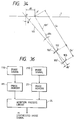
- Fig. 35 shows the flow of these signals.
- the image signals 110 and 210 output from the corresponding imaging systems are mechanically corrected to be equal to or smaller than the predetermined value (allowable value) ⁇ y0', images of the overlapping portion are subjected to a joint process, and thereafter, the image signals 110 can be synthesized to a single image signal 11 using, e.g., the image memories 111 and 211, an addition process circuit 24, and the like.
- Fig. 36 shows the flow of these signals.
- a panoramic image is generally an image corresponding to a short focal length.
- the correction signals ⁇ 1 and ⁇ 2 also assume small values (on the order of several seconds), and it is difficult to obtain angular response performance necessary for correcting the mis-registration under the influence of, e.g., non-sensitive bands of the convergence angle motors 104 and 204.
- a method of correcting the mis-registration amount of a image output from each imaging system by a means other than the convergence angle motor 104 or 204 is effective.
- the basic arrangement of the embodiment shown in Fig. 37 is substantially the same as that of the embodiment shown in Fig. 32, except that precision correction means 103a and 203a are added.
- the first and second imaging optical systems 102 and 202 are respectively constituted by lens groups 102a, 102b, 102c, and 102d, and lens groups 202a, 202b, 202c, and 202d.
- the lens groups 102b and 202b are zoom lens groups
- the lens groups 102d and 202d are focus lens groups.
- the zoom lens groups 102b and 202b are respectively driven by drive systems (zoom motors) 106 and 206, and similarly, the focus lens groups 102d and 202d are respectively driven by drive systems (focus motors) 107 and 207.
- Encoders (zoom encoders) 108 and 208 are provided to the zoom lens groups 102b and 202b of the imaging optical systems so as to obtain position information, in the optical axis direction, of the corresponding lens groups.
- encoders (focus encoders) 109 and 209 are provided to the focus lens groups 102d and 202d of the imaging optical systems so as to obtain position information, in the optical axis direction, of the corresponding lens groups.
- These encoders may comprise, e.g., externally attached members such as potentiometers, or may comprise systems such as pulse motors for detecting the position information, in the optical axis direction, of the lens by the drive systems themselves according to their drive method.
- the system of this embodiment further includes mechanism systems (not shown) for integrally rotating the optical system 102 and the image sensor 103, and the optical system 202 and the image sensor 203 in opposite directions by the same amount in planes respectively including optical axes 101 and 201, and drive systems (convergence angle motors) 104 and 204 for attaining such rotations.
- the system also includes rotational angle information detecting means 105 and 205. These means may comprise, e.g., externally attached members such as rotary encoders, or may comprise systems such as pulse motors for detecting the position information, in the optical axis direction, of angle information by the drive systems themselves according to their drive method. However, since the above-mentioned encoders are used for the auxiliary purpose, they are not always necessary in this embodiment.
- image memories 111 and 211 temporarily store signals of the overlapping portion of image signals 110 and 210.
- a horizontal image shift process portion 20 shifts the coordinates of image data in the image memory 111 in the horizontal direction by a predetermined amount X (e.g., one pixel), and writes the shifted image data in a image memory 112.
- control for calculating a difference ⁇ s between the contents of the image memories 112 and 211 is performed using a correlation calculation process portion 21 including a subtraction calculation process circuit and the like while sequentially changing the shift amount X so as to obtain a shift amount X0 for minimizing the difference ⁇ s .
- the shift amount X0 may be obtained by an interpolation calculation process by, e.g., approximating the relationship between the difference ⁇ s and the shift amount X by, e.g., a function.
- an interpolation calculation process by, e.g., approximating the relationship between the difference ⁇ s and the shift amount X by, e.g., a function.
- ⁇ y' (vertical) tan ⁇ 1 ⁇ f( ⁇ - 1) (5)
- coarse adjustment may be attained by commonly using the encoders 105 and 205 for outputting convergence angle information, and fine adjustment may be attained by the above-mentioned detection using the image signals, so as to further reduce the area of a region to be subjected to a correlation calculation.
- the correlation calculation method described here is normally called a matching method. However, the present invention is not particularly limited to this method, and other methods such as a gradient method may be used.
- the shift amount X0 corresponding to the minimum value indicates a relative mis-registration amount ⁇ y' itself of a image output from each imaging system, which mis-registration occurs due to a deviation of the optical axis 101 or 201.
- correction control of the positions in a plane of the sensors is performed using a correction signal 10 according to the mis-registration amount ⁇ y' of a image.
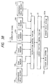
- the image sensors 103 and 203 are provided with drive systems 103a and 203a capable of shifting the sensors in the horizontal and vertical directions. Signals calculated by a calculation control portion 22, which received various signals, are received by a sensor position control portion 25, and correction drive control is executed using the drive systems 103a and 203a.
- Each of the drive systems 103a and 203a comprises, e.g., a piezo element or a piezoelectric bimorph. Fig. 38 shows the flow of these signals.
- two images can be synthesized using, e.g., image memories and an addition process circuit like in the above embodiment. Since the flow of signals in this synthesizing process portion is common to that shown in Fig. 36, its illustration will be omitted here.
- the movable ranges of the drive systems 103a and 203a may be defined as follows. That is, in order to prevent a region to be subjected to aberration correction of the imaging optical system from being increased very much, and to prevent the load on the specifications of the drive system from being increased, the convergence angle encoders 105 and 205 may also be used, and the correction amount may be classified into coarse and fine levels with reference to a predetermined level, so that coarse adjustment is attained by driving the convergence angle motors 104 and 204, and fine adjustment is attained by driving the drive systems 103a and 203a.
- Fig. 39 shows still another embodiment of the present invention.
- the image sensors 103 and 203 described in the embodiment shown in Fig. 37 are specified to camera tubes, and systems for driving the image sensors in the horizontal or vertical direction are not used.
- the arrangement except for the drive systems 103a and 203a and the method of obtaining the correction signal 10 are common to those in the above embodiment, and a detailed description thereof will be omitted.
- the camera tubes read image signals by scanning electron beams. Therefore, camera tube electron beam scanning locus control drivers 103b and 203b for controlling the scanning loci of electron beams upon reading of the image signals are provided. As described above, signals calculated by the calculation control portion 22 which received various signals are received by an electron beam scanning locus control portion 26, and correction control for shifting the scanning loci of electron beams using the drivers 103b and 203b is executed. With this control, images defined by the image signals 110 and 210 output from the image sensors 103 and 203 can be registered. Fig. 40 shows the flow of these signals.
- the above-mentioned technique for registering images by changing the scanning loci of electron beams is a general technique as DRC (Digital Registration Correction) in, e.g., a three-tube color television system.
- DRC Digital Registration Correction
- the mis-registration amounts of the image signals 110 and 210 output from the imaging systems are corrected to be equal to or smaller than a predetermined value (allowable value) ⁇ y0'
- two images can be synthesized using, e.g., image memories and an addition process circuit like in the above embodiment (since the flow of signals in this synthesizing process portion is common to that shown in Fig. 36, its illustration will be omitted here).
- Fig. 41 shows still another embodiment of the present invention, wherein the image sensors comprise solid-state imaging device in place of the camera tubes, and systems for driving the sensors in the horizontal or vertical direction are not used. More specifically, in this embodiment, the image sensors 103 and 203 described in the embodiment shown in Fig. 39 specifically use solid-state imaging device. Therefore, the basic arrangement and the method of obtaining the correction signal 10 are common to those in the embodiments shown in Figs. 37 and 39, and a detailed description thereof will be omitted.
- signals calculated by a calculation control portion 22, which received various signals, are received by a image position control portion 27.
- Image memories 111 and 211 temporarily store image signals 110 and 210. Images defined by image data in this stage are not registered due to convergence angle errors.
- a correction conversion portion 28 converts the coordinates of image data. More specifically, the portion 28 executes control for shifting image data in the memory 111 by the calculated mis-registration amount ⁇ y' of a image, and writing the shifted image data in a image memory 112.
- the image memories 112 and 111 are independently arranged for the sake of simplicity, a common memory may be used in place of these memories. When the coordinates of image data are shifted, a data interpolation calculation process may be performed as needed.
- the coordinates of image data in the image memory 111 are shifted.
- the coordinates of image data in the image memory 211 may be shifted.
- two images can be synthesized based on image data in the image memories 112 and 211, as shown in Fig. 36, using, e.g., the image memories and an addition process circuit like in the above embodiment.
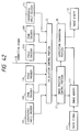
- correction control of the mis-registration amounts ⁇ y' of images due to convergence angle errors is executed.
- mis-registration amounts of images due to a difference between image formation magnifications of imaging optical systems must also be taken into consideration.
- Such mis-registration amounts can also be detected using image signals independently of the encoders 108 and 109 for obtaining position information, in the optical axis direction, of the lenses. Such an embodiment will be described below.
- Fig. 43 shows still another embodiment of the present invention.
- the basic arrangement of this embodiment is the same as that of the embodiment shown in Fig. 37, and since the same reference numerals in Fig. 43 denote the same parts as in Fig. 37, a detailed description thereof will be omitted.
- the image memories 111 and 211 temporarily store image signals of the overlapping portions of the image signals 110 and 210. In this stage, images defined by image data are not registered due to a difference between the image formation magnifications of the imaging optical systems 102 and 202. In this case, assume that mis-registration amounts ( ⁇ y' described above) of the central positions of two images have already been detected by, e.g., the method described in the embodiments shown in Figs. 32 to 42, and the central positions of the two images have been corrected.
- a magnification calculation process portion 29 converts the coordinates of image data in the image memory 111 by multiplying the coordinates with a constant k proportional to the distance from the center of the frame, and writes the coordinate-converted image data in a image memory 112.
- a difference ⁇ m between the contents of the image memories 112 and 211 is then calculated using a subtraction process circuit 30.
- the above-mentioned subtraction process is repeated while sequentially changing the constant k, thereby obtaining a constant k0 corresponding to the minimum difference ⁇ m .
- Fig. 44 shows the flow of these signals.
- the constant k0 represents the ratio of the image formation magnification of the imaging optical system 102 to that of the imaging optical system 202, and is defined as a correction signal 12.
- Fig. 45 shows a method of shortening the above-mentioned magnification correlation process time.
- Fig. 45 only image signal portions 110a1 and 110a2, and 210a1 and 210a2 corresponding to two upper and lower regions 111A1 and 111A2 and two upper and lower regions 211A1 and 211A2, which portions respectively include a line Y-Y' passing through a point 0 on an object surface 1 and perpendicular to a plane including the optical axes 101 and 201, and are separated from the central portion 0, are used.
- Representative points of these regions on the object surface are represented by Q and R, and images of these points are represented by Q1', R1', Q2', and R2'.
- the positional deviation correlation, in the vertical direction of these points may be calculated by, e.g., the method described in the embodiments shown in Figs.
- a mis-registration correction method when the zoom motors 106 and 206 have response performance necessary for obtaining a constant k0 for correcting the mis-registration amounts of images caused by the difference between the image formation magnifications to be equal to or smaller than a predetermined value (allowable value), servo control is executed by supplying a correction signal to one or both of the zoom motors 106 and 206 so as to compensate for the magnifications.
- a predetermined value allowable value
- correction control by changing the scanning loci of the electron beams described above with reference to Fig. 39 or correction control by converting the coordinates of the image memory in the above embodiment may be suitably executed.
- an interpolation calculation process of image data may be performed as needed.
- an imaging apparatus which can obtain a panoramic image in which the boundary line is not conspicuous can be provided.
- a relatively large aspect ratio is set.
- an image having a desired aspect ratio can be obtained by changing the convergence angle 2 ⁇ .
- Fig. 46 shows the principle of a synthesizing system.
- an image having a new aspect ratio is obtained by synthesizing images from right and left side imaging systems.
- the convergence angle 2 ⁇ is selected to be smaller than that of a panoramic image.
- optical axes 101 and 201 shown in Fig. 31 are set to be symmetrically inclined through ⁇ with respect to the normal O-O' to the object surface 1, so that two image fields overlap each other by a predetermined amount according to a selected aspect ratio of a frame.
- Fig. 47 shows a mode for converting an aspect ratio of 4 : 3 of images picked up by NTSC image sensors into an aspect ratio of 16 : 9 of an HD system.
- a desired aspect ratio is determined first, and the convergence angle corresponding to the determined aspect ratio is set by a setting means 115 (Fig. 48) by driving the convergence angle motors 104 and 204. Thereafter, the registration compensation method described in each of the above embodiments is applied to obtain a desired image.
- Fig. 49 shows a basic arrangement of a multi-lens imaging system according to still another embodiment of the present invention.
- the system shown in Fig. 49 includes a common object surface 1, and first and second imaging optical systems 102 and 202 having equivalent specifications, and normally comprising zoom lenses, as will be described later.
- Image sensors 103 and 203 similarly have equivalent specifications, and comprise camera tubes such as saticons, or solid-state imaging device such as CCDs.
- Fig. 49 illustrates a single-sensor type (or single-tube type) image sensor for the sake of simplicity, versatility will not be disturbed even when a two-sensor type (two-tube type) image sensor or three-sensor type (three-tube type) image sensor via a color separation system is used.
- Optical axes 101 and 201 of these imaging optical systems are set to cross at a point O on the object surface 1 and to be symmetrically inclined through ⁇ with respect to a normal O-O' to the object surface 1 while passing the point O.
- 2 ⁇ is defined as the convergence angle, and imaging operations are performed by changing the convergence angle according to a change in object distance S.
- Fig. 50 shows the detailed arrangement of the imaging optical systems 102 and 202
- Fig. 51 is a block diagram showing functions of the members constituting the imaging optical systems.
- the first and second imaging optical systems 102 and 202 are respectively constituted by lens groups 102a, 102b, 102c, and 102d, and lens groups 202a, 202b, 202c, and 202d.
- the lens groups 102b and 202b are zoom lens groups
- the lens groups 102d and 202d are focus lens groups.
- the zoom lens groups 102b and 202b are respectively driven by drive systems (zoom motors) 106 and 206, and similarly, the focus lens groups 102d and 202d are respectively driven by drive systems (focus motors) 107 and 207.
- the system of this embodiment further includes mechanism systems (not shown) for integrally rotating the optical system 102 and the image sensor 103, and the optical system 202 and the image sensor 203 in opposite directions by the same amount in planes respectively including optical axes 101 and 201, and drive systems (convergence angle motors) 104 and 204 for attaining such rotations.
- Angle encoders (rotational angle detecting means) 105 and 205 respectively measure the rotational angles of the imaging optical systems 102 and 202.
- Zoom encoders 108 and 208 respectively measure the moving amounts of the zoom lens groups 102b and 202b to obtain zoom ratios.
- Focus encoders 109 and 209 measure the positions of the focus lens groups.
- Image signals 110 and 210 are output from the image sensors 103 and 203, and are stored in image memories 111 and 211.
- x-, y- and z-axes are defined to have the above-mentioned point O on the object surface as an origin.
- the intersections between the imaging optical systems 102 and 202 and their optical axes 101 and 201 are represented by Q R and Q L , the distance from the front-side principal point of the imaging optical system (lens) 102 or 202 to the above-mentioned point O is represented by S0, and the distance from the rear-side principal point to the image sensor 103 or 203 is represented by S0' -
- a method of obtaining coordinates P2 (x0, z0) on the object surface 1 in the x-z plane shown in Fig. 53 will be briefly described below.
- intersections between the imaging optical systems 102 and 202 and their optical axes 101 and 201 are respectively represented by QR (x1, -z1) and Q L (-x1, -z1)
- x2 (S0 + S0')sin ⁇ (2-a)
- z2 (S0 + S0')cos ⁇ (2-b)
- the convergence angle 2 ⁇ is detected by the rotational angle detecting means 105 and 205 such as rotary encoders.
- the encoders (zoom encoders) 108 and 208 for obtaining position information, in the optical axis direction, of the corresponding lens groups are used, and the focal lengths f of the imaging optical systems 102 and 202 are obtained based on the signals output from these encoders.
- the encoders (focus encoders) 109 and 209 for obtaining position information, in the optical axis direction, of the corresponding lens groups are provided to the focus lens groups 102d and 202d of the imaging optical systems.
- the calculation control portion 12 calculates the object distances S0 to the imaging optical systems 102 and 202 on the basis of the signals from the focus encoders 109 and 209. Furthermore, the portion 12 calculates lens backs S0' of the imaging optical systems 102 and 202 together with the focal lengths f of the imaging optical systems 102 and 202.
- focal lengths f and the lens backs S0' of the two imaging optical systems 102 and 202 are caused to always coincide with each other by independently controlling the drive systems 106, 107, 206, and 207 on the basis of the signals from the encoders 108, 109, 208, and 209.
- the calculation control portion 12 calculates S0 (the distance from the front-side principal point of the imaging optical system (lens) to the intersection of the corresponding optical axis), S0' (the distance from the rear-side principal point of the imaging optical system (lens) to the image surface), and ⁇ (convergence angle) on the basis of the signals from the encoders 105, 108, 109, 205, 208, and 209.
- the image memories 111 and 211 temporarily store image signals 110 and 210.
- the correlation calculation process portion 13 performs a correlation calculation about image data stored in the image memories 111 and 211.
- Figs. 54A and 54B show the principle of a correlation calculation process.
- a pixel data group 112 having pixel data R ij at a point (x iR ', y jR ') as a center is defined as one block, and a correlation calculation is performed between this block and a corresponding image block on the image memory 211.
- Fig. 55 illustrates the relationship between a correlation value and an x' (y') axis coordinate in the correlation calculation in the horizontal and vertical directions.
- Fig. 54A and 54B show the principle of a correlation calculation process.
- a pixel data group 112 having pixel data R ij at a point (x iR ', y jR ') as a center is defined as one block, and a correlation calculation is performed between this block and a corresponding image block on the image memory 211.
- X L ' (y L ') corresponding to a maximum correlation value is obtained with a precision equal to or lower than the sampling pitch of the image sensor by, e.g., approximating the relationship near the correlation peak by a function.
- the block 112 is also defined for other pixel data R ij on the image memory 111, and a similar calculation process is executed to obtain X L ' and y L ' for each pixel data.
- the coordinates P R (x0 , y0, z0) on the object surface corresponding to each pixel data R ij on the image sensor 103 can be calculated from the relationship given by equation (5) using the image information (x iR ', x L ', y jR ') obtained by these series of processes, and the imaging conditions (S0, S0', ⁇ ).
- the correction process portion 14 executes a process on the basis of the coordinates P R and P L obtained by the above-mentioned process.
- a desired view position is input. At this time, when the view position is input, as shown in Fig.
- the coordinates (x iR(L) ', Y iR(L) ') on each image memory are coordinate-converted by a calculation process on the basis of equations (6-a) and (6-b), and the converted data are written in a image memory 15.
- the mis-registration amounts have been removed from the image data stored in the image memory 15, and the image data is ideally twice image data output from the image sensors 103 and 203. As a result, a high-fine output image can be obtained.
- an apparatus capable of obtaining an image having very high image quality and a desired aspect ratio and an apparatus capable of obtaining a panoramic image free from a conspicuous boundary line can be provided.
- a multi-lens imaging apparatus of the present invention When a multi-lens imaging apparatus of the present invention is connected to a display device such as a CRT via an image process apparatus, it can be utilized as a high-performance panoramic TV system, a 3D TV system, an HDTV system, and the like. Similarly, when the apparatus of the present invention is connected to a recording apparatus via the image process apparatus, it can be utilized as a high-performance recording system.
- This invention relates to a multi-lens imaging apparatus and, more particularly, to a multi-lens imaging apparatus for obtaining a single high-fine image by synthesizing a plurality of images obtained by picking up an image of a common object using a plurality of imaging systems and to an apparatus which can provide an image having an aspect ratio different from that of an image obtained by a single imaging apparatus, especially, a panoramic image, by synthesizing a plurality of images using a plurality of imaging systems.
- This invention has as its object to obtain a high-fine image by synthesizing images from a plurality of imaging systems and, more specifically, to correct mis-registration such as keystone distortions generated in the images.
Landscapes
- Engineering & Computer Science (AREA)
- Multimedia (AREA)
- Signal Processing (AREA)
- Physics & Mathematics (AREA)
- General Physics & Mathematics (AREA)
- Theoretical Computer Science (AREA)
- Testing, Inspecting, Measuring Of Stereoscopic Televisions And Televisions (AREA)
- Transforming Light Signals Into Electric Signals (AREA)
- Color Television Image Signal Generators (AREA)
- Studio Devices (AREA)
- Image Processing (AREA)
Abstract
Description
- The present invention relates to a multi-lens imaging apparatus and, more particularly, to a multi-lens imaging apparatus which obtains a single high-fine image by synthesizing a plurality of images obtained by picking up a common object image using a plurality of imaging systems and to an apparatus which can provide a image having a different aspect ratio from that of a image obtained by a single imaging apparatus, for example, a panoramic image, by synthesizing a plurality of images obtained using a plurality of imaging optical systems.
- When an ultra high-fine image consisting of 4,000 × 4,000 pixels is picked up by an imaging system, and the picked-up image is displayed on an ultra high-fine monitor, problems associated with techniques for achieving a high density and a high sensitivity in the imaging system are posed. As a method of solving such problems in the imaging system, the principle of a multi-lens imaging apparatus for picking up an image of a common object using two imaging systems each having a small number of pixels, and obtaining a single high-fine image by synthesizing the two images obtained by the two imaging systems has been proposed. In the multi-lens imaging apparatus based on this principle, as shown in Fig. 1, right and left
side imaging systems object 101 by shifting their sampling points by a 1/2 spatial phase pitch. A right side image IR obtained by the rightside imaging system 110R and a left side image IL obtained by the leftside imaging system 110L are synthesized by a microprocessor (to be referred to as a "CPU" hereinafter) 120, thereby obtaining a single high-fine output image IOUT as compared to a image obtained when the image of theobject 101 is picked up by a single imaging system. - Fig. 2 is an explanatory view for explaining a basic arrangement of the right and left
side imaging systems - The left
side imaging system 110L is constituted by a left side imagingoptical system 111L and a leftside image sensor 112L, and the rightside imaging system 110R is constituted by a right side imagingoptical system 111R and a rightside image sensor 112R. The right and left side imagingoptical systems side image sensors left imaging systems object surface 102, and these systems are arranged at positions axially symmetrical about a normal O-O' to theobject surface 102. When the angle formed between each of the optical axes LR and LL and the normal O-O' to the object surface 102 (to be referred to as an "inclination angle" hereinafter) is represented by ϑ, 2ϑ is defined as the convergence angle. - In the multi-lens imaging apparatus, when the object distance is changed, the convergence angle 2ϑ is changed by rotating each of the right and left
side imaging systems - However, in the above-mentioned multi-lens imaging apparatus, only the principle shown in Fig. 1 and the results of principle experiments for demonstrating the principle are presented, and no detailed arrangement of the multi-lens imaging apparatus is presented. Thus, a problem associated with how to arrange the detailed multi-lens imaging apparatus utilizing the above-mentioned principle remains unsolved. Since the optical axes LR and LL of the right and left
side imaging systems object surface 102, the right and left side images IR and IL obtained by the right and leftside image sensors - Since the optical systems are arranged to have a convergence angle therebetween in principle, mis-registration between images obtained from the two imaging operation systems may occur. Fig. 4A shows the outline of mis-registration in a multi-lens imaging system. The system shown in Fig. 4A includes imaging optical systems (lenses) 910 and 920, and
image sensors optical systems optical axes optical axes image sensors image 930, as shown in Fig. 4B. As a result, a high-fine image cannot be provided. - Conventionally, as a panoramic imaging apparatus using a plurality of imaging optical systems and designed for dynamic images, for example, Japanese Laid-Open Patent Application No. 63-8641 is known. In an apparatus of this type, in general, the angle formed between the imaging optical systems is set by mechanical adjustment, so that image fields contact each other. However, it is very difficult to strictly register two adjacent images, and the boundary line between the two images normally becomes conspicuous. For the same reason as described above, since it is difficult to re-focus objects having different object distances or to perform zooming of these objects, the above-mentioned apparatus is limited to a cut photographing use in units of scenes.
- As a method of changing the aspect ratio of a frame of a television or video signal (e.g., conversion between 4 : 3 of the NTSC and 16 : 9 of the HD or ED2), a method of trimming upper and lower portions or right and left portions of the frame is known. In this method, since a picked-up image is partially used, when an image is picked by an NTSC camera using a 4 : 3 image sensor, and is output onto a 16 : 9 HD monitor, a total of 25% upper and lower images are lost in addition to the fact that the number of pixels is originally short, thus considerably deteriorating image quality. Conversely, when an image is picked up by a 16 : 9 HD camera, and is output onto a 4 : 3 NTSC monitor, no problem associated with image quality is posed, but the horizontal field angle is decreased by 1/3.
- It is an object of the present invention to obtain a high-fine image by synthesizing images from a plurality of imaging systems and, more specifically, to correct mis-registration such as keystone distortions generated in the images.
- In order to achieve the above object, there is provided an apparatus comprising detection means for detecting a mis-registration amount between imaging systems, and means for controlling at least a mechanism system or an image process system, so that the mis-registration amount detected by the detection means becomes equal to or smaller than a predetermined value, whereby images obtained from the imaging systems are synthesized while being registered with each other.
- In order to achieve the above object, there is also provided an apparatus comprising means for detecting imaging conditions of a plurality of imaging systems, means for detecting position information of an object from image signals output from the imaging systems, and means for synthesizing images output from the imaging systems on the basis of the imaging conditions and the position information.
- According to the present invention, an image having a desired aspect ratio and almost free from image deterioration can be obtained, and a panoramic image in which a boundary line is not conspicuous can also be obtained.
- According to the present invention, when a plurality of images are synthesized, the mis-registration amount of overlapping images may be partially detected.
- According to the present invention, means for setting a convergence angle of imaging systems to be a predetermined value may be arranged so as to change the aspect ratio of an image.
-
- Fig. 1 is a view for explaining the principle of a multi-lens imaging apparatus for obtaining a single high-fine image by synthesizing two images obtained by picking up an image of a common object using two imaging systems;
- Fig. 2 is an explanatory view for explaining a basic arrangement of right and left side imaging systems shown in Fig. 1;
- Fig. 3 is an explanatory view for explaining keystone distortions generated in images obtained by right and left side image sensors shown in Fig. 1;
- Figs. 4A and 4B are explanatory views of mis-registration occurring in the prior art;
- Figs. 5A and 5B show a multi-lens imaging apparatus according to an embodiment of the present invention, in which Fig. 5A is a perspective view showing the arrangement of right and left imaging systems, and Fig. 5B is a block diagram for explaining operations of keystone distortion correction signal generation portions;
- Fig. 6 is an explanatory view for explaining the principle of correcting keystone distortions in the keystone distortion correction signal generation portions shown in Fig. 5B;
- Fig. 7 is an explanatory view for explaining the principle of correcting keystone distortions in the keystone distortion correction signal generation portions shown in Fig. 5B;
- Fig. 8 is an explanatory view for explaining the principle of correcting keystone distortions in the keystone distortion correction signal generation portions shown in Fig. 5B;
- Fig. 9 is an explanatory view for explaining operations of camera tube electron beam scanning locus control drivers shown in Fig. 5B;
- Fig. 10 is a perspective view showing the arrangement of right and left side imaging systems in a multi-lens imaging apparatus according to another embodiment of the present invention;
- Fig. 11 is a block diagram for explaining operations of correction conversion portions in the multi-lens imaging apparatus according to the embodiment shown in Fig. 10;
- Fig. 12 is a perspective view showing the arrangement of right and left side imaging systems in a multi-lens imaging apparatus according to still another embodiment of the present invention;
- Fig. 13 is a block diagram showing operations of correction optical systems shown in Fig. 12;
- Fig. 14 is an explanatory view for explaining the principle of correcting keystone distortions in the correction optical systems shown in Fig. 12;
- Fig. 15 is an explanatory view for explaining the principle of correcting keystone distortions in the correction optical systems shown in Fig. 12;
- Fig. 16 is an explanatory view for explaining the principle of correcting keystone distortions in the correction optical systems shown in Fig. 12;
- Figs. 17A and 17B show a multi-lens imaging apparatus according to still another embodiment of the present invention, in which Fig. 17A is a perspective view showing the arrangement of right and left side imaging systems, and Fig. 17B is a block diagram for explaining a correction method of keystone distortions;
- Fig. 18 is an explanatory view for explaining operations of a keystone distortion conversion portion and a subtraction process circuit shown in Fig. 17B;
- Fig. 19 is a graph showing the relationship between the image difference and the inclination angle (conversion variable);
- Figs. 20A and 20B show a multi-lens imaging apparatus according to still another embodiment of the present invention, in which Fig. 20A is a perspective view showing the arrangement of right and left side imaging systems, and Fig. 20B is a block diagram for explaining a correction method of keystone distortions;
- Figs. 21A to 21C show a multi-lens imaging apparatus according to still another embodiment of the present invention, in which Fig. 21A is a perspective view showing the arrangement of right and left side imaging systems, Fig. 21B is a block diagram for explaining an operation of a control portion, and Fig. 21C is a block diagram for explaining an image synthesizing operation;
- Fig. 22 is an explanatory view for explaining a basic arrangement of imaging systems in the multi-lens imaging apparatus according to the embodiment shown in Figs. 21A to 21C;
- Fig. 23 is a view for explaining response characteristics of each convergence angle motor shown in Fig. 21A;
- Figs. 24A and 24B show a multi-lens imaging apparatus according to still another embodiment of the present invention, in which Fig. 24A is a perspective view showing the arrangement of right and left side imaging systems, and Fig. 24B is a block diagram for explaining an operation of a calculation control portion;
- Figs. 25A and 25B show a multi-lens imaging apparatus according to still another embodiment of the present invention, in which Fig. 25A is a perspective view showing the arrangement of right and left side imaging systems, and Fig. 25B is a block diagram for explaining an operation of a calculation control portion;
- Figs. 26A and 26B show a multi-lens imaging apparatus according to still another embodiment of the present invention, in which Fig. 26A is a perspective view showing the arrangement of right and left side imaging systems, and Fig. 26B is a block diagram for explaining an operation of a calculation control portion;
- Fig. 27 is a block diagram for explaining an operation of a correlation calculation process portion in a multi-lens imaging apparatus according to still another embodiment of the present invention;
- Fig. 28 is a block diagram for explaining an operation of a magnification correlation calculation process portion in a multi-lens imaging apparatus according to still another embodiment of the present invention;
- Fig. 29 is an explanatory view for explaining a method of shortening the correlation calculation time in the magnification correlation calculation process portion shown in Fig. 28;
- Fig. 30 is an explanatory view for explaining another method of shortening the correlation calculation time in the magnification correlation calculation process portion shown in Fig. 28;
- Fig. 31 is a view showing a basic arrangement according to still another embodiment of the present invention;
- Fig. 32 is a perspective view of optical systems of the embodiment shown in Fig. 31;
- Fig. 33 is a diagram showing the flow of a signal process for calculating a mis-registration amount;
- Fig. 34 is a view for explaining a problem;
- Fig. 35 is a diagram showing the flow of a compensation signal process in the embodiment shown in Fig. 31;
- Fig. 36 is a diagram showing the flow of a image signal process in the embodiment shown in Fig. 31;
- Fig. 37 is a perspective view showing optical systems according to still another embodiment of the present invention;
- Fig. 38 is a diagram showing the flow of a compensation signal process in the embodiment shown in Fig. 37;
- Fig. 39 is a perspective view showing optical systems according to still another embodiment of the present invention;
- Fig. 40 is a diagram showing the flow of a compensation signal process in the embodiment shown in Fig. 39;
- Fig. 41 is a perspective view showing optical systems according to still another embodiment of the present invention;
- Fig. 42 is a diagram showing the flow of a compensation signal process in the embodiment shown in Fig. 41;
- Fig. 43 is a perspective view showing optical systems according to still another embodiment of the present invention;
- Fig. 44 is a diagram showing the flow of a signal process for calculating a mis-registration amount;
- Fig. 45 is a perspective view for explaining an optical effect;
- Fig. 46 is an explanatory view for explaining a method of obtaining an image having a desired aspect ratio;
- Fig. 47 is an explanatory view of the aspect ratio;
- Fig. 48 is a view showing an optical basic arrangement;
- Fig. 49 is a view showing a basic arrangement according to still another embodiment of the present invention;
- Fig. 50 is a perspective view showing the detailed arrangement of the embodiment shown in Fig. 49;
- Fig. 51 is a block diagram showing relationships among functions in the embodiment shown in Fig. 49;
- Fig. 52 is an explanatory view associated with a method of calculating three-dimensional position information of an object;
- Fig. 53 is an explanatory view associated with a method of calculating two-dimensional position information of an object;
- Figs. 54A and 54B are views showing a correlation calculation process;
- Fig. 55 is a graph showing a correlation value; and
- Fig. 56 is an explanatory view of an image correction process.
- Figs. 5A and 5B show an arrangement of a multi-lens imaging apparatus according to an embodiment of the present invention.
- The multi-lens imaging apparatus of this embodiment obtains a single high-fine image by synthesizing two images obtained by picking up an image of a common object using two imaging systems (right and left
side imaging systems 10R and 10L) - The arrangement of the right and left
side imaging systems - The left
side imaging system 10L includes a left side imaging optical system 11L (see Fig. 8), a leftside image sensor 12L comprising a camera tube, and a camera tube electron beam scanning locus control driver 31L for controlling the locus of scanning of the electron beam emitted from the camera tube constituting the leftside image sensor 12L. The left side imagingoptical system 11L includeslens groups 21L to 24L including azoom lens group 22L and afocus lens group 24L, azoom motor 25L as a driving system for driving thezoom lens group 22L, afocus motor 26L as a driving system for driving thefocus lens group 24L, a mechanism system (not shown) and a driving system (convergence angle motor 27L) for integrally rotating the left side imagingoptical system 11L and the leftside image sensor 12L in a plane including an optical axis LL, and a rotational angle detecting means 28L for detecting the rotational angle of theconvergence angle motor 27L. As the rotationalangle detecting means 28L, for example, an externally attached member such as a rotary encoder may be used, or a means such as a pulse motor for detecting the rotational angle by the driving system itself according to a driving method may be used. The rightside imaging system 10R has the same arrangement as that of the leftside imaging system 10L. - Assume that when the
focus motor 26L and thezoom motor 25L of the left side imagingoptical system 11L are independently controlled by signals from a focus encoder 42L and a zoom encoder 41L, and afocus motor 26R and azoom motor 25R of a right side imagingoptical system 11R are independently controlled by signals from a focus encoder 42R and a zoom encoder 41R, a focal length f of the left side imagingoptical system 11L always coincides with a focal length f of the right side imagingoptical system 11R, and an image formation magnification β of the left side imagingoptical system 11L always coincides with an image formation magnification β of the right side imagingoptical system 11R. - At this time, a keystone distortion correction signal generation portion 32L shown at the left side in Fig. 5B can calculate the focal length f of the left side imaging
optical system 11L on the basis of a signal from the zoom encoder 41L, and a keystone distortion correction signal generation portion 32R shown at the right side in Fig. 5B can calculate the focal length f of the right side imagingoptical system 11R on the basis of a signal from the zoom encoder 41R. Also, since the keystone distortion correction signal generation portion 32L can calculate an object distance to the left side imagingoptical system 11L on the basis of a signal from the focus encoder 42L,it can calculate the image formation magnification β of the left side imagingoptical system 11L. Similarly, the keystone distortion correction signal generation portion 32R can calculate the image formation magnification β of the right side imagingoptical system 11R on the basis of a signal from the focus encoder 42R. Furthermore, the keystone distortion correction signal generation portions 32R and 32L can calculate inclination angles ϑ on the basis of signals from the corresponding rotationalangle detecting means - As shown in Fig. 5B, the multi-lens imaging apparatus of this embodiment further includes the keystone distortion correction signal generation portion 32L for generating a keystone distortion correction signal on the basis of the output signals from the rotational
angle detecting means 28L, the zoom encoder 41L, and the focus encoder 42L of the left side imagingoptical system 11L, and outputting the keystone distortion correction signal to the camera tube electron beam scanning locus control driver 31L, the keystone distortion correction signal generation portion 32R for generating a keystone distortion correction signal on the basis of the output signals from the rotationalangle detecting means 28R, the zoom encoder 41R, and the focus encoder 42R of the right side imagingoptical system 11R, and outputting the keystone distortion correction signal to a camera tube electron beam scanning locus control driver 31R, and asynthesizing process portion 38 for forming a single high-fine image by synthesizing a right side image IR sent from a rightside image sensor 12R and a left side image IL sent from the leftside image sensor 12L. Note that the high-fine image formed by thesynthesizing process portion 38 is output to a highfine monitor 40, and is displayed thereon. - The principle of correcting keystone distortions in the keystone distortion correction signal generation portions 32R and 32L will be described below with reference to Figs. 6 to 8.
- When keystone distortions are respectively generated in the left side image IL obtained by the left
side image sensor 12L constituting the leftside imaging system 10L and in the right side image IR obtained by the rightside image sensor 12R constituting the rightside imaging system 10R, if a point A on the Y-axis of a required image I indicated by a broken line in Fig. 6 is defined as a reference point, a point AL on the left side image IL corresponding to the point A is deviated leftward in Fig. 6 by a horizontal deviation amount Δy, and a point AR on the left side image IR corresponding to the point A is deviated rightward in Fig. 6 by a horizontal deviation amount Δy. - If an arbitrary point P₀ on the required image I indicated by a broken line in Fig. 7 is defined as a reference point, a point P₁ on the left side image IR corresponding to the point P₀ is deviated rightward in Fig. 7 by a horizontal deviation amount Δy₀ʼ and is deviated upward in Fig. 7 by a vertical deviation amount Δz₀' if the coordinates of the point P₀ are represented by (y₀ʼ, z₀'), and the coordinates of the point P₁ are represented by (y₀ʼ +Δy₀', z₀'+Δz₀'). However, the horizontal and vertical deviation amounts Δy₀ʼ and Δz₀' can be calculated from the focal length f and the image formation magnification β of the right side imaging
optical system 11R and the inclination angle ϑ of the rightside imaging system 10R. This principle will be described in more detail below with reference to Fig. 8. - As shown in Fig. 8, when the right and left
imaging systems object surface 2, so that their optical axes LR and LL cross at a point O on theobject surface 2, a conjugate object surface 3 passing through the point O on theobject surface 2 and conjugate with the rightside image sensor 12R is assumed. - A point P₀ on the
object surface 2 and a point P₁ on the conjugate object surface 3, which satisfy
optical system 11R and an object height y₁ of the point P₁ with respect to the right side imagingoptical system 11R satisfy:

A length OQ₁ between an intersection Q₁ of a perpendicular drawn from the point P₁ to the optical axis LR, andpoint 0 is expressed by:

Furthermore, if image heights on the rightside image sensor 12R with respect to the object heights y₀ and y₁ are respectively represented by y₀' and y₁', the horizontal deviation amount Δy₀' is given by:

If the distance (object distance) from the front-side principal point of the right side imagingoptical system 11R to theobject surface 2 is represented by S₀, and the distance from the rear-side principal point of the right side imagingoptical system 11R to the image surface of the rightside image sensor 12R is represented by S₀' the image height y₁' is expressed by:

Thus, from equations (1), (2), and (4), the image height y₁' can be expressed by:

Also, the image height y₀' is expressed by:

For this reason, from equations (3), (5), and (6), the horizontal deviation amount Δy₀' can be expressed by:

Similarly, the vertical deviation amount Δz₀' can be expressed by:
In this case, the distance S₀' from the rear-side principal point of the right side imagingoptical system 11R to the image surface of the rightside image sensor 12R is expressed as follows using the focal length f and the image formation magnification β of the right side imaging optical system 11R:

Therefore, the horizontal and vertical deviation amounts Δy₀' and Δz₀' can be respectively calculated from the focal length f and the image formation magnification β of the right side imagingoptical system 11R and the inclination angle ϑ of the rightside imaging system 10R. The same applies to the leftside imaging system 10L. - The operation of the multi-lens imaging apparatus of this embodiment will be described below.
- When the
object surface 2 is located at an infinity distance position, no keystone distortions are generated in the right and left side images IR and IL obtained by the right and leftside image sensors synthesizing process portion 38 synthesizes the right and left side images IR and IL without executing the keystone distortion correction of the right and left side images IR and IL, and outputs the synthesized image to the highfine monitor 40. - On the other hand, when the
object surface 2 is located at a finite distance position, the right and leftside imaging systems convergence angle motors side imaging systems object surface 2. Thereafter, the inclination angles ϑ of the right and leftside imaging systems convergence angle motors side imaging system 10L are shifted by a 1/2 spatial phase pitch from those on the optical axis LR of the rightside imaging system 10R. At this time, in synchronism with control of the inclination angles ϑ by theconvergence angle motors optical systems zoom motors focus motors - In this case, since the imaging operations are performed in a state wherein the right and left
imaging systems side image sensors optical system 11L calculates the horizontal and vertical deviation amounts Δy₀' and Δz₀' of each point on the left side image IL obtained by the leftside image sensor 12L using the output signals from the rotationalangle detecting means 28L and the focus encoder 42L and the zoom encoder 41L from equations (7) to (9) described above, generates a keystone distortion correction signal for correcting the keystone distortion generated in the left side image IL, and outputs the signal to the camera tube electron beam scanning locus control driver 31L of the left side imagingoptical system 11L. In this case, the distance S₀' is calculated from equation (9). Alternatively, the distance S₀' may be calculated from the output signal from the focus encoder 42L. The keystone distortion correction signal generation portion 32R of the right side imagingoptical system 11R operates in the same manner as described above. - The camera tube electron beam scanning locus control driver 31L of the left side imaging
optical system 11L changes the scanning locus of the electron beam emitted from the camera tube constituting the leftside image sensor 12L on the basis of the keystone distortion correction signal sent from the keystone distortion correction signal generation portion 32L, thereby correcting the keystone distortion generated in the left side image IL. More specifically, the camera tube electron beam scanning locus control driver 31L of the left side imagingoptical system 11L changes the scanning locus of the electron beam by controlling a deflection circuit of the camera tube constituting the leftside image sensor 12L on the basis of the keystone distortion correction signal sent from the keystone distortion correction signal generation portion 32L, thereby scanning the left side image IL along a point A₁ → a point B₁, a point A₂ → a point B₂, a point A₃ →a point B₃, and a point A₄ → a point B₄, as indicated by the left-hand side figure in Fig. 9. As a result, the left side image IL output from the camera tube constituting the leftside image sensor 12L is converted into the required image I, which is scanned along a point a₁ → a point b₁, a point a₂ → a point b₂, a point a₃ → a point b₃, and a point a₄ → a point b₄, as indicated by the right-hand side figure in Fig. 9, and the converted image is input to thesynthesizing process portion 38. - In place of the rotational
angle detecting means imaging systems optical systems - Fig. 10 is a perspective view showing the arrangement of the right and left
side imaging systems - The multi-lens imaging apparatus of this embodiment has the following differences from the multi-lens imaging apparatus of the embodiment shown in Figs. 5A and 5B.
- (1) Both the right and left
side image sensors - (2) The apparatus of this embodiment does not have the camera tube electron scanning locus control drivers 31R and 31L of the right and left
imaging systems - (3) The apparatus of this embodiment has a left side image memory 51L for left side image data output from the left
side image sensor 12L, and a right side image memory 51R for right side image data output from the rightside image sensor 12R, as shown in Fig. 11. - (4) The apparatus of this embodiment has a correction conversion portion 52L (to be described later) between the left side image memory 51L and the synthesizing
processing portion 38, and also has a correction conversion portion 52R (to be described later) between the right side image memory 51R and the synthesizingprocessing portion 38. - The operation of the multi-lens imaging apparatus of this embodiment will be described below.
- When the
object surface 2 is located at an infinity distance position, since no keystone distortions are generated in the right and left side images IR and IL obtained by the right and leftside image sensors synthesizing process portion 38 without executing keystone distortion correction of the right and left side images IR and IL, and the right and left side images IR and IL are synthesized by thesynthesizing process portion 38. The synthesized image is then output to the highfine monitor 40. - On the other hand, when the
object surface 2 is located at a finite distance position, the right and leftside imaging systems convergence angle motors side imaging systems object surface 2. Thereafter, the inclination angles ϑ of the right and leftside imaging systems convergence angle motors side imaging system 10L are shifted by a 1/2 spatial phase pitch from those on the optical axis LR of the rightside imaging system 10R. At this time, in synchronism with control of the inclination angles ϑ by theconvergence angle motors optical systems zoom motors focus motors - In this case, since the imaging operations are performed in a state wherein the right and left
imaging systems side image sensors optical system 11L calculates the horizontal and vertical deviation amounts Δy₀' and Δz₀' of each point on the left side image IL obtained by the leftside image sensor 12L using the output signals from the rotationalangle detecting means 28L and the focus encoder 42L and the zoom encoder 41L from equations (7) to (9) described above, generates a keystone distortion correction signal for correcting the keystone distortion generated in the left side image IL, and outputs the signal to the correction conversion portion 52L. The correction conversion portion 52L converts the coordinate of the left side image data of the left side image IL read out from the left side image memory 51L so as to cancel the horizontal and vertical deviation amounts Δy₀' and Δz₀' on the basis of the keystone distortion correction signal sent from the keystone distortion correction signal generation portion 32L, thereby correcting the keystone distortion generated in the left side image IL. In this case, the distance S₀' is calculated from equation (9). Alternatively, the distance S₀' may be calculated from the output signal from the focus encoder 42L. The keystone distortion correction signal generation portion 32R and the correction conversion portion 52R of the right side imagingoptical system 11R perform the same operation as described above. - As a result, the
synthesizing process portion 38 synthesizes the right and left side image data of the right and left side images IR and IL, which are respectively sent from the correction conversion portions 52R and 52L, and in which the keystone distortions are corrected, so that a single high-fine synthesized image can be displayed on the highfine monitor 40. - In the multi-lens imaging apparatus of this embodiment, the output signal from the correction conversion portion 52L is supplied to the
synthesizing process portion 38. Alternatively, the output signal from the correction conversion portion 52L may be stored again in the left side image memory 51L, and thereafter, the data may be supplied from the left side image memory 51L to thesynthesizing process portion 38. The same applies to the output signal from the other correction conversion portion 52R. - Fig. 12 is a perspective view showing an arrangement of the right and left
imaging systems - In the multi-lens imaging apparatus of this embodiment, lenses constituting correction optical systems 61R and 61L (to be described later) are decentered in the vertical direction with respect to the optical axes LR and LL so as to generate distortions, thereby correcting keystone distortions generated in the right and left side images IR and IL obtained by the right and left
side image sensors optical system 11L and the leftside image sensor 12L, and the correction optical system 61R arranged between the right side imagingoptical system 11R and the rightside image sensor 12R, in place of the correction conversion portions 52L and 52R. - The operation of the multi-lens imaging apparatus of this embodiment will be described below.
- When the
object surface 2 is located at an infinity distance position, since no keystone distortions are generated in the right and left side images IR and IL obtained by the right and leftside image sensors synthesizing process portion 38 without executing keystone distortion correction of the right and left side images IR and IL, and the synthesized image is output to the highfine monitor 40. - On the other hand, when the
object surface 2 is located at a finite distance position, the right and leftside imaging systems convergence angle motors side imaging systems object surface 2. Thereafter, the inclination angles ϑ of the right and leftside imaging systems convergence angle motors side imaging system 10L are shifted by a 1/2 spatial phase pitch from those on the optical axis LR of the rightside imaging system 10R. At this time, in synchronism with control of the inclination angles ϑ by theconvergence angle motors optical systems zoom motors focus motors - In this case, since the imaging operations are performed in a state wherein the right and left
imaging systems side image sensors optical system 11L calculates the horizontal and vertical deviation amounts Δy₀ʼ and Δz₀ʼ of each point on the left side image IL obtained by the leftside image sensor 12L using the output signals from the rotationalangle detecting means 28L and the focus encoder 42, and the zoom encoder 41L from equations (7) to (9) described above, generates a keystone distortion correction signal for correcting the keystone distortion generated in the left side image IL, and outputs the signal to the correction optical system 61L of the left side imagingoptical system 11L. The correction optical system 61L of the left side imagingoptical system 11L decenters at least one of lenses constituting the correction optical system 61L in the vertical direction with respect to the optical axis LL on the basis of the keystone distortion correction signal sent from the keystone distortion correction signal generation portion 32L so as to generate a distortion, thereby correcting the keystone distortion generated in the left side image IL. In this case, the distance S₀' is calculated from equation (9). Alternatively, the distance S₀' may be calculated from the output signal from the focus encoder 42L. The keystone distortion correction signal generation portion 32R and the correction optical system 61R of the right side imagingoptical system 11R perform the same operations as described above. - The principle of correcting keystone distortions will be described below with reference to Fig. 14.
- The
object surface 2 is inclined through the inclination angle ϑ with respect to the optical axis LR, and its image is formed on the rightside image sensor 12R. If the distance from theobject surface 2 to the right side imagingoptical system 11R is represented by S₁, the distance from the right side imagingoptical system 11R to the image surface of the rightside image sensor 12R is represented by S₁', and a point O on theobject surface 2 is defined as an intersection between the optical axis LR and theobject surface 2, an image formation magnification βH at a height H of theobject surface 2 is expressed as follows by a paraxial calculation:
where - β =
- the image formation magnification at the point O on the
object surface 2 - φ =
- the refracting power of the correction optical system 61R
- Vp =
- the third-order distortion of the convex lens 63R
- Bp =
- the astigmatism coefficient of the convex lens 63R
- Pp =
- the Petzval's sum of the convex lens 63R
- Vq =
- the third-order distortion on the
object surface 2 side of the concave lens 62R - Bq =
- the astigmatism coefficient on the
object surface 2 side of the concave lens 62R - Pq =
- the Petzval's sum on the
object surface 2 side of the concave lens 62R - h =
- the incident position of the paraxial object ray onto the correction optical system 61R
- a =
- the incident angle of the paraxial object ray onto the correction optical system 61R
- When the right side image IR in which the keystone distortion is corrected in this manner, and which is obtained from the right
side image sensor 12R, and the left side image IL in which the keystone distortion is similarly corrected, and which is obtained from the leftside image sensor 12L are synthesized by thesynthesizing process portion 38, a single high-fine image can be displayed on the high fine monitor 40 (see Fig. 13). - Figs. 17A and 17B show a multi-lens imaging apparatus according to still another embodiment of the present invention.
- The multi-lens imaging apparatus of this embodiment obtains a single high-fine image by synthesizing two images obtained by picking up an image of a common object using two imaging systems (right and left
side imaging systems 10R and 10L). - The arrangement of the right and left
side imaging systems - The left
side imaging system 10L includeslens groups 21L to 24L including azoom lens group 22L and afocus lens group 24L, azoom motor 25L as a driving system for driving thezoom lens group 22L, afocus motor 26L as a driving system for driving thefocus lens group 24L, a mechanism system (not shown) and a driving system (convergence angle motor 27L) for integrally rotating the left side imagingoptical system 11L and a leftside image sensor 12L in a plane including an optical axis LL, and a rotational angle detecting means 28L for detecting the rotational angle of theconvergence angle motor 27L, which constitute a left side imagingoptical system 11L. As the rotationalangle detecting means 28L, for example, an externally attached member such as a rotary encoder may be used, or a means such as a pulse motor for detecting the rotational angle by the driving system itself according to a driving method may be used. The rightside imaging system 10R has the same arrangement as that of the leftside imaging system 10L. - Assume that when the
focus motor 26L and thezoom motor 25L of the left side imagingoptical system 11L are independently controlled by signals from the focus encoder 42L and the zoom encoder 41L, and afocus motor 26R and azoom motor 25R of a right side imagingoptical system 11R are independently controlled by signals from a focus encoder 42R and a zoom encoder 41R, a focal length f of the left side imagingoptical system 11L always coincides with a focal length f of the right side imagingoptical system 11R, and an image formation magnification β of the left side imagingoptical system 11L always coincides with an image formation magnification β of the right side imagingoptical system 11R. - At this time, a
calculation control portion 71 shown in Fig. 17B can calculate the focal length f of the left side imagingoptical system 11L on the basis of a signal from the zoom encoder 41L, and can calculate the focal length f of the right side imagingoptical system 11R on the basis of a signal from the zoom encoder 41R. Also, since thecalculation control portion 71 can calculate an object distance to the left side imagingoptical system 11L on the basis of a signal from the focus encoder 42L, it can calculate the image formation magnification β of the left side imagingoptical system 11L, and similarly, it can calculate the image formation magnification β of the right side imagingoptical system 11R on the basis of a signal from the focus encoder 42R. Furthermore, thecalculation control portion 71 can calculate inclination angles ϑ from the signals output from the rotationalangle detecting means - The output signals from the zoom encoders 41R and 41L and the focus encoders 42R and 42L are input to the
calculation control portion 71, as shown in Fig. 17B. Thecalculation control portion 71 can calculate the distance S₀' from the rear-side principal point of the left side imagingoptical system 11L to the image surface of the leftside image sensor 12L and the distance S₀' from the rear-side principal point of the right side imagingoptical system 11R to the image surface of the rightside image sensor 12R from equation (9) described above:

Left side image data of a left side image IL output from the leftside image sensor 12L is stored in a left side image memory 72L, and right side image data of a right side image IR output from the rightside image sensor 12R is stored in a right side image memory 72R. - The principle of correcting keystone distortions generated in the right and left images IR and IL by a keystone
distortion conversion portion 73, second right and left side image memories 74R and 74L, and asubtraction process circuit 75 shown in Fig. 17B will be described below with reference to Figs. 18 and 19. - The keystone
distortion conversion portion 73 calculates horizontal and vertical deviation amounts Δy₀' and Δz₀' of predetermined several image points from equations (7) and (8) described above using the left side image data read out from the left side image memory 72L, the right side image data read out from the right side image memory 72R, and the distances S₀' sent from thecalculation control portion 71. At this time, the inclination angle ϑ is defined as a conversion variable (an angle is not detected), and the horizontal and vertical deviation amounts Δy₀' and Δz₀' are calculated by substituting, e.g., ϑ = ϑ₁ (ϑ₁ is an arbitrary value). Thereafter, the keystonedistortion conversion portion 73 shifts the coordinates of the image points in the right and left side image memories 72R and 72L by the calculated horizontal and vertical deviation amounts Δy₀' and Δz₀', and writes the shifted right and left side image data in the second right and left side image memories 74R and 74L, respectively. Thereafter, thesubtraction process circuit 75 reads out the coordinate-shifted right and left side image data respectively from the second right and left side image memories 74R and 74L, and calculates a sum (to be referred to as an "image difference" hereinafter) δS1 of the absolute values of differences of these data. Subsequently, the keystonedistortion conversion portion 73 changes the inclination angle ϑ (conversion variable) to be ϑ = ϑ₂, and an image difference δs2 is similarly calculated. - When the above-mentioned operations are repeated, since the relationship between the inclination angle ϑ (conversion variable) and the image difference δs can be obtained, as shown in, e.g., Fig. 19, an inclination angle ϑ₀ (conversion variable) at which the image difference δs assumes a minimum value is obtained. The keystone
distortion conversion portion 73 calculates the horizontal and vertical deviation amounts Δy₀ʼ and Δz₀ʼ of all image points of the left side image data from equations (7) and (8) using the inclination angle ϑ₀ (conversion variable) at which the image difference δs assumes a minimum value, thereafter, shifts the coordinates of all the image points of the left side image data by the calculated horizontal and vertical deviation amounts Δy₀ʼ and Δz₀ʼ, and writes the shifted left side image data in the second left side image memory 74L. As a result, the left side image data in which the keystone distortion is corrected is written in the second left side image memory 74L. - Therefore, when the left side image data in which the keystone distortion is corrected, and which is written in the second left side image memory 74L, and the right side image data in which the keystone distortion is corrected, and which is written in the second right side image memory 74R are synthesized by a synthesizing process portion (not shown), a single high-fine image can be displayed on a high fine monitor (not shown).
- Figs. 20A and 20B show a multi-lens imaging apparatus according to still another embodiment of the present invention.
- The arrangement of the multi-lens imaging apparatus of this embodiment is substantially the same as that of the multi-lens imaging apparatus of the embodiment shown in Figs. 17A and 17B, except that the right and left
image sensors distortion conversion portion 73 controls camera tube electron beam scanning locus drivers 31R and 31L according to the calculated horizontal and vertical deviation amounts Δy₀' and Δz₀'. - Since the operations of the camera tube electron beam scanning locus drivers 31R and 31L and the principle of correcting keystone distortions in the multi-lens imaging apparatus of this embodiment are the same as those in the multi-lens imaging apparatuses in the embodiments shown in Figs. 5A and 5B and Figs. 17A and 17B, a repetitive description will be avoided here.
- Figs. 21A to 21C show a multi-lens imaging apparatus according to still another embodiment of the present invention, and Fig. 22 shows a basic arrangement of imaging systems in the multi-lens imaging apparatus of the embodiment shown in Figs. 21A to 21C.
- The multi-lens imaging apparatus of this embodiment obtains a single high-fine image by synthesizing two images obtained by picking up an image of a common object using two sets of imaging systems (right and left
side imaging systems 10R and 10L) . - As shown in Fig. 22, the left
side imaging system 10L is constituted by a left side imagingoptical system 11L and a leftside image sensor 12L, and the rightside imaging system 10R is constituted by a right side imagingoptical system 11R and a rightside image sensor 12R. The right and left side imagingoptical systems side image sensors imaging systems object surface 2, and these systems are arranged at positions axially symmetrical about a normal O-O' to theobject surface 2. - In this multi-lens imaging apparatus, when the object distance is changed, the convergence angle 2ϑ is changed by rotating each of the right and left
side imaging systems - The arrangement of the right and left
imaging systems - The left
side imaging system 10L includeslens groups 21L to 24L including azoom lens group 22L and afocus lens group 24L, azoom motor 25L as a driving system for driving thezoom lens group 22L, afocus motor 26L as a driving system for driving thefocus lens group 24L, a mechanism system (not shown) and a driving system (convergence angle motor 27L) for integrally rotating the left side imagingoptical system 11L and a leftside image sensor 12L in a plane including an optical axis LL, and a rotational angle detecting means 28L for detecting the rotational angle of theconvergence angle motor 27L, which constitute a left side imagingoptical system 11L. As the rotationalangle detecting means 28L, for example, an externally attached member such as a rotary encoder may be used, or a means such as a pulse motor for detecting the rotational angle by the driving system itself according to a driving method may be used. The rightside imaging system 10R has the same arrangement as that of the leftside imaging system 10L. - A control method for the
convergence angle motors - When the right and left
imaging systems angle detecting means 28L detects the angular deviation ΔϑL with respect to an angle ϑ (see Fig. 22) formed between the optical axis LL of the leftside imaging system 10L and the normal O-O' to theobject surface 2, and the rotationalangle detecting means 28R detects the angular deviation ΔϑR with respect to an angle ϑ formed between the optical axis RR of the rightside imaging system 10R and the normal O-O' to theobject surface 2. The angular deviations ΔϑR and ΔϑL output from the rotationalangle detecting means control portion 231. - Assume that the
convergence angle motors - For the sake of simplicity, as shown in Fig. 23, only a mis-registration amount Δa of a image output from the right
side imaging system 10R when the optical axis LR of the rightside imaging system 10R is deviated by the angular deviation ΔϑR will be examined below. If the distance (object distance) from the front-side principal point of the right side imagingoptical system 11R to theobject surface 2 is represented by S₀, the distance from the rear-side principal point of the right side imagingoptical system 11R to the rightside image sensor 12R is represented by S₁, and the deviation amount of the optical axis LR of the rightside imaging system 10R in theobject surface 2 is represented by Δy, when the angular deviation ΔϑR is small, we have:

If the image formation magnification of the right side imagingoptical system 11R is represented by β, we have:

Furthermore, if the focal length of the right side imagingoptical system 11R is represented by f, we have:

From equations (15) to (17), the mis-registration amount Δa of the image is given by:

Therefore, assume that theconvergence angle motor 27R shown in Fig. 21A has sufficient response characteristics for an angle (ΔϑR) necessary for correcting the mis-registration amount Δa of the image given by equation (18) to be equal to or smaller than an allowable value Δa₀. The same applies to theconvergence angle motor 27L of the left side imagingoptical system 11L. - The
control portion 231 supplies a correction signal -ΔϑL to theconvergence angle motor 27L of the leftside imaging system 10L as a control target value, and supplies a correction signal -ΔϑR to theconvergence angle motor 27R of the rightside imaging system 10R as a control target value, as shown in Fig. 21B. As a result, the mis-registration amount Δa of the image obtained by each of the right and leftimaging systems - When the mis-registration amounts of the images are corrected as described above, a image signal output from the left
side image sensor 12L is stored in a left side image memory 232L, and a image signal output from the rightside image sensor 12R is stored in a right side image memory 232R, as shown in Fig. 21C. Thereafter, these images are synthesized by asynthesizing process circuit 233, and a synthesized image signal is output. - Therefore, since the multi-lens imaging apparatus of this embodiment can synthesize images obtained by the right and left
imaging systems side image sensors image side sensors synthesizing process circuit 233 can obtain a single high fine image. - In the multi-lens imaging apparatus of this embodiment, when a solid state imaging element is used as each of the right and left
side image sensors side image sensors control portion 231 may supply a correction signal -(ΔϑL+ΔϑR) to one of the twoconvergence angle motors convergence angle motors - Figs. 24A and 24B show a multi-lens imaging apparatus according to still another embodiment of the present invention.
- In the multi-lens imaging apparatus of the embodiment shown in Figs. 21A to 21C, as can be understood from equation (18), when the focal lengths f of the right and left side imaging
optical systems control portion 231 also take small values (e.g., on the order of several seconds), and it becomes difficult to obtain angular response performance necessary for correction under the influence of, e.g., non-sensitive bands of theconvergence angle motors - In the multi-lens imaging apparatus of the embodiment shown in Figs. 24A and 24B, the image mis-registration amount Δa given by equation (18) is calculated, and is corrected by means other than the
convergence angle motors - (1) Zoom encoders 41R and 41L for detecting the focal lengths f of the right and left side imaging
optical systems zoom motors - (2) Focus encoders 42R and 42L for detecting the object distances S₀ with respect to the right and left side imaging
optical systems focus motors - (3) The apparatus of this embodiment includes horizontal direction drive systems 243R and 243L for respectively driving the right and left
side image sensors - (4) The apparatus of this embodiment also includes a calculation control portion 244 (to be described later; see Fig. 24B).
- The operation of the multi-lens imaging apparatus of this embodiment will be described below.
- In the left side imaging
optical system 11L, when thezoom motor 25L is controlled by a signal from the zoom encoder 41L, and thefocus motor 26L is controlled by an output signal from the focus encoder 42L, the focal length f and the image formation magnification β are caused to always coincide with each other. In the right side imagingoptical system 11R, the focal length f and the image formation magnification β are similarly caused to always coincide with each other. - Therefore, the focal lengths f and the image formation magnifications β of the right and left side imaging
optical systems optical systems calculation control portion 244, and thecalculation control portion 244 calculates equation (18) described above, thus obtaining the mis-registration amounts Δa₀ of images. Thecalculation control portion 244 controls the horizontal direction drive systems 243R and 243L to move the right and leftside image sensors - As each of the zoom encoders 41R and 41L and the focus encoders 42R and 42L, for example, an externally attached member such as a potentiometer may be used, or a means such as a pulse motor for detecting the rotational angle by the driving system itself according to a driving method may be used. Also, each of the horizontal direction drive systems 243R and 243L may comprise, e.g., a piezo element or piezoelectric bimorph.
- When a swing motion in the vertical direction occurs due to insufficient precision of a mechanism system (not shown) for driving the convergence angle motor, encoders for respectively detecting inclination angles (elevation angles) Δφ₁, in the vertical direction, of the right and left
side imaging systems side image sensors side image sensors imaging systems

For the following reasons, the mis-registration amounts Δb, in the vertical direction, of images may be corrected upon combination of coarse adjustment attained by theconvergence angle motors - (1) to prevent regions to be subjected to aberration correction of the right and left side imaging
optical systems - (2) to prevent the loads on the horizontal direction drive systems 243R and 243L from being increased.
- Figs. 25A and 25B show a multi-lens imaging apparatus according to still another embodiment of the present invention.
- In the multi-lens imaging apparatus of this embodiment, the right and left
side image sensors - More specifically, in the multi-lens imaging apparatus of this embodiment, since the camera tubes read video signals by scanning electron beams, the scanning loci of the electron beams by the camera tubes are controlled by the camera tube electron beam scanning locus control drivers 251R and 251L in accordance with the mis-registration amounts Δa obtained by equation (18) above, thereby registering the images expressed by the video signals output from the right and left
side image sensors - Figs. 26A and 26B show a multi-lens imaging apparatus according to still another embodiment of the present invention.
- In the multi-lens imaging apparatus of this embodiment, the right and left
side image sensors imaging systems - (1) The apparatus of this embodiment does not include the horizontal direction drive systems 243R and 243L.
- (2) The apparatus of this embodiment includes a
correction conversion portion 261 and a second leftside image memory 262 between the left side image memory 232L and the synthesizing process circuit 233 (see Fig. 26B). - The operation of the multi-lens imaging apparatus of this embodiment will be described below.
- The
calculation control portion 244 receives the output signals from the rotationalangle detecting means correction conversion portion 261 converts the coordinates of image data output from the left side image memory 232L in accordance with the mis-registration amount Δa calculated by thecalculation control portion 244, and writes the converted image data in the second leftside image memory 262. As a result, when thesynthesizing process circuit 233 synthesizes the image data respectively output from the second leftside image memory 262 and the right side image memory 232R, a high-fine synthesized image signal can be obtained. - Note that the
correction conversion portion 261 and a second left side image memory may be arranged between the rightside image memory 232R and thesynthesizing process circuit 233 in place of thecorrection conversion portion 261 and the second leftside image memory 262. The left side image memory 232L and the second leftside image memory 262 may be replaced with a common one. Furthermore, when the coordinates of image data output from the left side image memory 232L are converted, an interpolation calculation process of image data may be performed as needed. - In each of the multi-lens imaging apparatus of the embodiments shown in Figs. 21A to 26B according to the present invention, the mis-registration amounts Δa of images are calculated based on the output signals from the rotational
angle detecting means imaging systems - Fig. 27 is a block diagram for explaining an operation of a correlation calculation process portion in a multi-lens imaging apparatus according to still another embodiment of the present invention.
- The multi-lens imaging apparatus of this embodiment has the following differences from the multi-lens imaging apparatus of the embodiment shown in Figs. 26A and 26B.
- (1) The apparatus of this embodiment includes a correlation
calculation process portion 271 for performing a correlation calculation between image data output from the second leftside image memory 262 and image data output from the right side image memory 232R to obtain a correlation value δs. When the correlation value δs is equal to or larger than a predetermined value, theportion 271 calculates a new shift amount X so that the correlation value δs becomes equal to or smaller than the predetermined value, and outputs the calculated shift amount X to thecorrection conversion portion 261. - (2) When the
correction conversion portion 261 writes image data output from the left side image memory 232L in the second leftside image memory 262, it shifts the coordinates of the image data in the horizontal and vertical directions by the shift amount X sent from the correlationcalculation process portion 271. - The operation of the multi-lens imaging apparatus of this embodiment will be described below.
- The
correction conversion portion 261 shifts the coordinates of image data output from the left side image memory 232L in the horizontal and vertical directions by a predetermined shift amount X (e.g., by one pixel each in the horizontal and vertical directions), and writes the coordinate-shifted image data in the second leftside image memory 262. The correlationcalculation process portion 271 performs a correlation calculation between image data output from the second leftside image memory 262 and image data output from the right side image memory 232R to obtain a correlation value δs. When the correlation value δs is equal to or larger than a predetermined value, theportion 271 calculates a new shift amount X so that the correlation value δs becomes equal to or smaller than the predetermined value, and outputs the calculated shift amount X to thecorrection conversion portion 261. Thecorrection conversion portion 261 shifts the coordinates of image data output from the left side image memory 232L in the horizontal and vertical directions by the new shift amount X, and writes the coordinate-shifted image data in the second leftside image memory 262. Thereafter, the above-mentioned operations are repeated until the correlation value δs becomes equal to or smaller than the predetermined value. After the correlation value δs becomes equal to or smaller than the predetermined value, a synthesizing process circuit (not shown) synthesizes image data respectively output from the second leftside image memory 262 and the right side image memory 232R, thus obtaining a high-fine synthesized image signal. - In order to shorten the correlation calculation time in the correlation
calculation process portion 271, for example, the correlation calculation may be performed using only image data at the central portion of a frame. As a correlation calculation method, a known matching method, gradient method, or the like may be used. - Since a finally obtained shift amount X₀ indicates the mis-registration amount Δa of a image, the correlation
calculation process portion 271 may calculate a correction signal corresponding to the finally obtained shift amount X₀, and the correction control methods described in the embodiments shown in Figs. 21A to 25B, i.e., the following control methods may be executed: - (1) convergence angle control
- (2) correction drive control using drive systems capable of shifting the image sensors in the horizontal and vertical directions
- (3) correction control for changing the electron beam scanning loci
- Fig. 28 is a block diagram for explaining an operation of a magnification correlation calculation process portion in a multi-lens imaging apparatus according to still another embodiment of the present invention.
- The multi-lens imaging apparatus of this embodiment has substantially the same arrangement as that of the multi-lens imaging apparatus of the embodiment shown in Fig. 27, except that the apparatus of this embodiment includes a magnification correlation
calculation process portion 281, acalculation process portion 282, and a third leftside image memory 283. - The operation of multi-lens imaging apparatus of this embodiment will be described below.
- Assume that the central positions of images obtained by the right and left
side imaging systems - The
calculation process portion 282 converts the coordinates of image data output from the left side image memory 232L by multiplying the coordinates with a constant k proportional to the distance from the center of the frame, and writes the coordinate-converted image data in the third leftside image memory 283. The magnification correlationcalculation process portion 281 executes a correlation calculation between image data output from the third leftside image memory 283 and image data output from the right side image memory 232R to obtain a correlation value δs. When the correlation value δs is equal to or larger than a predetermined value, theportion 281 calculates a new constant k, so that the correlation value δs becomes equal to or smaller than the predetermined value, and outputs the constant to thecalculation process portion 282. Thecalculation process portion 282 converts the coordinates of image data output from the left side image memory 232L by multiplying the coordinates with the new constant k, and writes the coordinate-converted image data in the third leftside image memory 283. Thereafter, the above-mentioned operations are repeated until the correlation value δs becomes equal to or smaller than the predetermined value. After the correlation value δs becomes equal to or smaller than the predetermined value, a synthesizing process circuit (not shown) synthesizes image data respectively output from the second leftside image memory 262 and the right side image memory 232 thus obtaining a high-fine synthesized image signal from which the mis-registration amounts of images caused by a difference between the image formation magnifications of the right and left imagingoptical systems - Since a finally obtained constant k₀ indicates the ratio of image formation magnifications of the right and left imaging
optical systems calculation process portion 281 may calculate a correction signal according to the finally obtained constant k₀, and may execute the correction control methods described in the embodiments shown in Figs. 21A to 25B. - In order to shorten the correlation calculation time of the magnification correlation
calculation process portion 281, the correlation calculation may be executed using only image signals in a hatched region (a region obtained by narrowing a horizontal process portion) having as its center a line Y-Y' passing through a point O on theobject surface 2 and perpendicular to the plane including two optical axes LR and LL, as shown in Fig. 29. Since this region has symmetricity from the arrangement conditions of the right and left side imagingoptical systems - In order to shorten the correlation calculation time of the magnification correlation
calculation process portion 281, a positional deviation correlation in the vertical direction may be calculated by the method described in the embodiment shown in Figs. 26A and 26B using only image signals in two upper and lower hatched regions which have as their center a line Y-Y' passing through the point O on theobject surface 2 and perpendicular to the plane including two optical axes LR and LL, and which are separated from the point O, as shown in Fig. 30. When representative points of these regions are represented by Q and R, and when images of these representative points Q and R on the leftside image sensor 12L are represented by QL' and RL' and images of these representative points Q and R on the rightside image sensor 12R are represented by QR' and RR', a ratio of a line QL' - RL' to a line QR' and RR' is calculated to obtain the final constant k₀. This technique utilizes the fact that the detection sensitivity of the difference between the image formation magnifications can be improved toward the periphery of the frame, and the fact that the difference between the image formation magnifications can be regarded as a positional deviation in a small region. - The final constant k₀ is obtained as described above, and the following correction control can be made on the basis of this constant k₀.
- (1) When the
zoom motors zoom motors - (2) When it is difficult for the
zoom motors - Each of the multi-lens imaging apparatuses according to the above-mentioned embodiments of the present invention comprises two imaging systems. However, the present invention can also be applied to an apparatus using three or more imaging systems.
- An embodiment of an apparatus for displaying images while partially overlapping image fields using a plurality of imaging systems, e.g., for obtaining a panoramic image or a 3D-2D mixed image is disclosed.
- Fig. 31 shows the basic arrangement of a panoramic multi-lens imaging system according to the present invention. The system includes a
common object surface 1, and first and second imagingoptical systems image sensors image sensors Optical axes object surface 1 so as to satisfy a condition that image fields to be picked up by these sensors overlap each other by a predetermined amount. Note that 2ϑ will be referred to as the convergence angle, and is changed according to the image formation magnifications of the imaging optical systems (the object distances and the focal lengths of photographing lenses). - Fig. 32 shows the detailed arrangement of the imaging optical systems and the image sensors. In Fig. 32, a support structure such as a lens barrel is not shown.
- The first and second imaging
optical systems lens groups lens groups lens groups lens groups zoom lens groups focus lens groups zoom lens groups optical systems encoders lens groups - Encoders (focus encoders) 109 and 209 are provided to the
focus lens groups optical system 102 and theimage sensor 103, and theoptical system 202 and theimage sensor 203 in opposite directions by the same amount in planes respectively includingoptical axes information detecting means - A method of obtaining mis-registration amounts on the basis of image signals will be described below with reference to Figs. 33 and 34.
Image memories shift process portion 20 shifts the coordinates of image data in theimage memory 111 in the horizontal direction by a predetermined amount X (e.g., one pixel), and writes the shifted image data in aimage memory 112. Furthermore, control for calculating a difference δs between the contents of theimage memories calculation process portion 21 including a subtraction calculation process circuit and the like while sequentially changing the shift amount X so as to obtain a shift amount X₀ for minimizing the difference δs. At this time, the shift amount X₀ is normally obtained by an interpolation calculation process by, e.g., approximating the relationship between the difference δs and the shift amount X by, e.g., a function. - In order to shorten the correlation calculation time, a method using only image data at the central portion of the frame of the overlapping portion, i.e., a region which includes a point O on the
object surface 1 and whose vertical and horizontal widths are shortened is effective. Alternatively, coarse adjustment may be attained by commonly using theencoders - The shift amount X₀ corresponding to the minimum value indicates a relative mis-registration amount Δy' itself of a image output from each imaging system, which mis-registration occurs due to a deviation of the
optical axis 101 or 201 (Fig. 31) from an ideal optical axis. Therefore, convergence angle correction control is performed using acorrection signal 10 for canceling the mis-registration amount Δy' of the image. The method of obtaining the mis-registration amount will be described below. - Assume that an imaging operation is performed while the convergence angle has a deviation from a predetermined value, i.e., the
optical axis optical axis 101 is deviated to an axis 101', as shown in Fig. 34, will be described below. The mis-registration amount with respect to theoptical axis 201 can be obtained by the same equations, as is obvious to those who are skilled in the art from the arrangement of the optical systems, and even when both theoptical axes

where Δy is the deviation (PP' in Fig. 34), generated in the object surface, of an intersection P of theoptical axis 101 and theobject surface 1 from a predetermined value, and S₀ is the distance from the front-side principal point of the imaging optical system (lens) 102 to an object (similarly, S₀' is the distance from the rear-side principal point to the image surface). If the image formation magnification of the imagingoptical system 102 is represented by β, the magnification β can be expressed from its definition by:

If the focal length of the imaging system (lens) is represented by f, we have:

From equations (1), (2), and (3), the mis-registration amount Δy' is given by:

Thezoom lens group 102b of the imaging optical system shown in Fig. 32 is provided with the encoder (zoom encoder) 108 for obtaining position information, in the optical axis direction, of the lens group, and the focal length f of the imagingoptical system 102 can be obtained based on a signal output from theencoder 108. Similarly, thefocus lens group 102d of the imaging optical system is provided with the encoder (focus encoder) 109 for obtaining position information, in the optical axis direction, of the lens group, and the image formation magnification β of the imagingoptical system 102 can be obtained based on both the signals from thezoom encoder 108 and thefocus encoder 109. Assume that the focal lengths f and the image formation magnifications β of the two imagingoptical systems drive systems encoders calculation control portion 22 obtains all the parameters except for Δϑ1 in equation (4). - The calculated angular deviations Δϑ1 and Δϑ2 are supplied to a convergence
angle control portion 23. Note that theconvergence angle motors control portion 23 supplies Δϑ1 to theconvergence angle motor 104 as a correction signal, and supplies Δϑ2 to theconvergence angle motor 204 as a direct control target value. Alternatively, the sum of Δϑ1 and Δϑ2 may be supplied to one of theconvergence angle motors - In this manner, after the mis-registration amounts of the image signals 110 and 210 output from the corresponding imaging systems are mechanically corrected to be equal to or smaller than the predetermined value (allowable value) Δy0', images of the overlapping portion are subjected to a joint process, and thereafter, the image signals 110 can be synthesized to a
single image signal 11 using, e.g., theimage memories addition process circuit 24, and the like. Fig. 36 shows the flow of these signals. When such processes are sequentially performed as needed, a good panoramic image can always be obtained. - A panoramic image is generally an image corresponding to a short focal length. However, as can be understood from equation (4), when the focal length f of the imaging optical system is large, or when the allowable value of the mis-registration amount of a image is small, the correction signals Δϑ1 and Δϑ2 also assume small values (on the order of several seconds), and it is difficult to obtain angular response performance necessary for correcting the mis-registration under the influence of, e.g., non-sensitive bands of the
convergence angle motors convergence angle motor - The first and second imaging
optical systems lens groups lens groups lens groups lens groups zoom lens groups focus lens groups zoom lens groups focus lens groups optical system 102 and theimage sensor 103, and theoptical system 202 and theimage sensor 203 in opposite directions by the same amount in planes respectively includingoptical axes information detecting means - As has been described above with reference to Fig. 33,
image memories shift process portion 20 shifts the coordinates of image data in theimage memory 111 in the horizontal direction by a predetermined amount X (e.g., one pixel), and writes the shifted image data in aimage memory 112. Furthermore, control for calculating a difference δs between the contents of theimage memories calculation process portion 21 including a subtraction calculation process circuit and the like while sequentially changing the shift amount X so as to obtain a shift amount X₀ for minimizing the difference δs. At this time, the shift amount X₀ may be obtained by an interpolation calculation process by, e.g., approximating the relationship between the difference δs and the shift amount X by, e.g., a function. When a swing motion in the vertical direction occurs as well due to insufficient precision of the mechanism system for driving the convergence angle motors, the same process as that for the horizontal direction may be performed for the vertical direction, and a two-dimensional (plane) mis-registration amount can be obtained. Note that a mis-registration amount Δy' (vertical) of a image in the vertical direction is given by:

In order to shorten the correlation calculation time, a method using only image data at the central portion of the frame of the overlapping portion, i.e., a region which includes a point O on theobject surface 1 and whose vertical and horizontal widths are shortened is effective. Alternatively, coarse adjustment may be attained by commonly using theencoders optical axis - Therefore, in this embodiment, correction control of the positions in a plane of the sensors is performed using a
correction signal 10 according to the mis-registration amount Δy' of a image. More specifically, theimage sensors drive systems calculation control portion 22, which received various signals, are received by a sensorposition control portion 25, and correction drive control is executed using thedrive systems drive systems - After the mis-registration amounts of the image signals 110 and 210 output from the imaging systems are corrected to be equal to or smaller than Δy0' as a predetermined allowable value, two images can be synthesized using, e.g., image memories and an addition process circuit like in the above embodiment. Since the flow of signals in this synthesizing process portion is common to that shown in Fig. 36, its illustration will be omitted here.
- The movable ranges of the
drive systems convergence angle encoders convergence angle motors drive systems - Fig. 39 shows still another embodiment of the present invention. In this embodiment, the
image sensors drive systems correction signal 10 are common to those in the above embodiment, and a detailed description thereof will be omitted. - In general, the camera tubes read image signals by scanning electron beams. Therefore, camera tube electron beam scanning
locus control drivers calculation control portion 22 which received various signals are received by an electron beam scanninglocus control portion 26, and correction control for shifting the scanning loci of electron beams using thedrivers image sensors - Fig. 41 shows still another embodiment of the present invention, wherein the image sensors comprise solid-state imaging device in place of the camera tubes, and systems for driving the sensors in the horizontal or vertical direction are not used. More specifically, in this embodiment, the
image sensors correction signal 10 are common to those in the embodiments shown in Figs. 37 and 39, and a detailed description thereof will be omitted. - As shown in Fig. 42, signals calculated by a
calculation control portion 22, which received various signals, are received by a imageposition control portion 27.Image memories correction conversion portion 28 converts the coordinates of image data. More specifically, theportion 28 executes control for shifting image data in thememory 111 by the calculated mis-registration amount Δy' of a image, and writing the shifted image data in aimage memory 112. Although theimage memories image memory 111 are shifted. Of course, the coordinates of image data in theimage memory 211 may be shifted. Then, two images can be synthesized based on image data in theimage memories - In the above embodiment, correction control of the mis-registration amounts Δy' of images due to convergence angle errors is executed. In some cases, mis-registration amounts of images due to a difference between image formation magnifications of imaging optical systems must also be taken into consideration.
- Such mis-registration amounts can also be detected using image signals independently of the
encoders - Fig. 43 shows still another embodiment of the present invention. The basic arrangement of this embodiment is the same as that of the embodiment shown in Fig. 37, and since the same reference numerals in Fig. 43 denote the same parts as in Fig. 37, a detailed description thereof will be omitted. The
image memories optical systems - As one method of a magnification correlation calculation process, the following method is known. More specifically, a magnification
calculation process portion 29 converts the coordinates of image data in theimage memory 111 by multiplying the coordinates with a constant k proportional to the distance from the center of the frame, and writes the coordinate-converted image data in aimage memory 112. A difference δm between the contents of theimage memories subtraction process circuit 30. The above-mentioned subtraction process is repeated while sequentially changing the constant k, thereby obtaining a constant k₀ corresponding to the minimum difference δm. Fig. 44 shows the flow of these signals. The constant k₀ represents the ratio of the image formation magnification of the imagingoptical system 102 to that of the imagingoptical system 202, and is defined as acorrection signal 12. - Fig. 45 shows a method of shortening the above-mentioned magnification correlation process time.
- In Fig. 45, only image signal portions 110a1 and 110a2, and 210a1 and 210a2 corresponding to two upper and lower regions 111A1 and 111A2 and two upper and lower regions 211A1 and 211A2, which portions respectively include a line Y-Y' passing through a
point 0 on anobject surface 1 and perpendicular to a plane including theoptical axes central portion 0, are used. Representative points of these regions on the object surface are represented by Q and R, and images of these points are represented by Q1', R1', Q2', and R2'. The positional deviation correlation, in the vertical direction of these points may be calculated by, e.g., the method described in the embodiments shown in Figs. 32 to 42, and the ratio of a length Q1'-R1' to a length Q2'-R2' may be calculated to obtain the constant k₀. This technique utilizes the fact that the detection sensitivity of the difference between the image formation magnifications can be improved toward the periphery of the frame, and the fact that the difference between the image formation magnifications can be regarded as a positional deviation in a small region. The constant k₀ is obtained, as described above, and the following correction control can be executed based on this constant. - More specifically, as a mis-registration correction method, when the
zoom motors zoom motors - When it is difficult for the
zoom motors - As described above, an imaging apparatus which can obtain a panoramic image in which the boundary line is not conspicuous can be provided.
- In the above embodiment, a relatively large aspect ratio is set. However, an image having a desired aspect ratio can be obtained by changing the convergence angle 2ϑ. Fig. 46 shows the principle of a synthesizing system. In Fig. 46, an image having a new aspect ratio is obtained by synthesizing images from right and left side imaging systems.
- In this case, although the basic arrangement is the same as that shown in Fig. 31, the convergence angle 2ϑ is selected to be smaller than that of a panoramic image.
- More specifically, the
optical axes object surface 1, so that two image fields overlap each other by a predetermined amount according to a selected aspect ratio of a frame. - For example, Fig. 47 shows a mode for converting an aspect ratio of 4 : 3 of images picked up by NTSC image sensors into an aspect ratio of 16 : 9 of an HD system.
- Therefore, a desired aspect ratio is determined first, and the convergence angle corresponding to the determined aspect ratio is set by a setting means 115 (Fig. 48) by driving the
convergence angle motors - The descriptions of the above embodiments have been made under an assumption that an object is a substantially flat one or can be regarded as a flat object. Next, an embodiment that can be applied to an object whose depth cannot be ignored will be described below.
- Fig. 49 shows a basic arrangement of a multi-lens imaging system according to still another embodiment of the present invention. The system shown in Fig. 49 includes a
common object surface 1, and first and second imagingoptical systems Image sensors -
Optical axes object surface 1 and to be symmetrically inclined through ϑ with respect to a normal O-O' to theobject surface 1 while passing the point O. Note that 2ϑ is defined as the convergence angle, and imaging operations are performed by changing the convergence angle according to a change in object distance S. - Fig. 50 shows the detailed arrangement of the imaging
optical systems optical systems lens groups lens groups lens groups lens groups zoom lens groups focus lens groups optical system 102 and theimage sensor 103, and theoptical system 202 and theimage sensor 203 in opposite directions by the same amount in planes respectively includingoptical axes - Angle encoders (rotational angle detecting means) 105 and 205 respectively measure the rotational angles of the imaging
optical systems Zoom encoders zoom lens groups Focus encoders image sensors image memories - Functions of a
calculation control portion 12, acorrelation calculation portion 13, and acorrection calculation portion 14 will be described later. - Detection of position information of an object when imaging operations are performed in an arrangement shown in Fig. 52 will be described below.
- As shown in Fig. 52, x-, y- and z-axes are defined to have the above-mentioned point O on the object surface as an origin.
- The intersections between the imaging
optical systems optical axes image sensor object surface 1 in the x-z plane shown in Fig. 53 will be briefly described below. - If the intersections between the imaging
optical systems optical axes


Similarly, as for intersections OR' (x₂, -z₂) and OL' (-x₂, -z₂) between theimage sensors optical axes


As shown in Fig. 53, if image points on theimage sensors image sensors


At this time, if a line passing the points PR' and QR is represented by fR (S₀, S₀', ϑ, xR'), and a line passing the points PL' and QL is represented by fL (S₀, S₀', ϑ, xL'), the point P₂ (x₀, z₀) on the object surface corresponds to the coordinates of the intersection of these two lines according to the definition. - Also, as shown in Fig. 52, y₀ can be expressed as follows in association with the imaging optical system 102:

SR is the distance from the object point P₂ (x₀, z₀) to the front-side principal point of the imagingoptical system 102 in Fig. 53, and SR' is the distance from the rear-side principal point of the imagingoptical system 102 to the image pint PR' on theimage sensor 103 in Fig. 53. - At this time, a point P (x₀, y₀, z₀) in Fig. 52 is defined by:

That is, the point P is expressed by a function of imaging conditions (S₀, S₀', ϑ) and an output image (xR', xL', yR(L)') of each image sensor, and position information on the object surface can be obtained by detecting these parameters. - The method of obtaining parameters in the above-mentioned process will be described below with reference to Figs. 50 and 51. First, the convergence angle 2ϑ is detected by the rotational angle detecting means 105 and 205 such as rotary encoders. The encoders (zoom encoders) 108 and 208 for obtaining position information, in the optical axis direction, of the corresponding lens groups are used, and the focal lengths f of the imaging
optical systems focus lens groups calculation control portion 12 calculates the object distances S₀ to the imagingoptical systems focus encoders portion 12 calculates lens backs S₀' of the imagingoptical systems optical systems optical systems drive systems encoders - As described above, the
calculation control portion 12 calculates S₀ (the distance from the front-side principal point of the imaging optical system (lens) to the intersection of the corresponding optical axis), S₀' (the distance from the rear-side principal point of the imaging optical system (lens) to the image surface), and ϑ (convergence angle) on the basis of the signals from theencoders image memories - The correlation
calculation process portion 13 performs a correlation calculation about image data stored in theimage memories pixel data group 112 having pixel data Rij at a point (xiR', yjR') as a center is defined as one block, and a correlation calculation is performed between this block and a corresponding image block on theimage memory 211. Fig. 55 illustrates the relationship between a correlation value and an x' (y') axis coordinate in the correlation calculation in the horizontal and vertical directions. In Fig. 55, XL' (yL') corresponding to a maximum correlation value is obtained with a precision equal to or lower than the sampling pitch of the image sensor by, e.g., approximating the relationship near the correlation peak by a function. Theblock 112 is also defined for other pixel data Rij on theimage memory 111, and a similar calculation process is executed to obtain XL' and yL' for each pixel data. - The coordinates PR (x₀, y₀, z₀) on the object surface corresponding to each pixel data Rij on the
image sensor 103 can be calculated from the relationship given by equation (5) using the image information (xiR', xL', yjR') obtained by these series of processes, and the imaging conditions (S₀, S₀', ϑ). - The same calculation process is executed for each pixel data Lij (xiL', YjL') of the
image sensor 203 to obtain xR' and yR' for each pixel, and the coordinates PL (x₀, y₀, z₀) on the object surface corresponding to each pixel data Lij on theimage sensor 203 are then calculated. Note that the coordinates PR and PL on the object surface do not always coincide with each other. - The
correction process portion 14 executes a process on the basis of the coordinates PR and PL obtained by the above-mentioned process. In thecorrection process portion 14, a desired view position is input. At this time, when the view position is input, as shown in Fig. 56, image points (x', y') corresponding to the coordinate values can be obtained as follows using the above-mentioned imaging conditions S₀ and S₀' and the coordinates PR(L) (x₀, y₀, z₀) on the object surface:


The coordinates (xiR(L)', YiR(L)') on each image memory are coordinate-converted by a calculation process on the basis of equations (6-a) and (6-b), and the converted data are written in aimage memory 15. The mis-registration amounts have been removed from the image data stored in theimage memory 15, and the image data is ideally twice image data output from theimage sensors - The embodiment described above with reference to Fig. 49 and subsequent drawings can be applied to a panoramic image and images having various aspect ratios. In this case, since an operation for extracting corresponding points on at least partial regions of a plurality of images is required, the images must partially overlap each other. A plurality of imaging optical systems of every embodiment does not always lie in the same mode. For a different purpose, a different mode imaging optical system is sometimes used.
- With the above-mentioned arrangements of the present invention, the following effects can be expected.
- Even when images obtained by imaging systems suffer from keystone distortions, the keystone distortions can be removed, and the images can be converted into desired images, thus obtaining a high-fine image free from keystone distortions.
- Since at least one of a mechanism system or image process system is controlled so as to correct a mis-registration amount detected by a detecting means to be equal to or smaller than a predetermined value, images obtained by imaging systems can be registered and synthesized. For this reason, an apparatus which can obtain a high-fine image by picking up an image of a common object using a plurality of imaging systems can be provided.
- Also, an apparatus capable of obtaining an image having very high image quality and a desired aspect ratio, and an apparatus capable of obtaining a panoramic image free from a conspicuous boundary line can be provided.
- When a multi-lens imaging apparatus of the present invention is connected to a display device such as a CRT via an image process apparatus, it can be utilized as a high-performance panoramic TV system, a 3D TV system, an HDTV system, and the like. Similarly, when the apparatus of the present invention is connected to a recording apparatus via the image process apparatus, it can be utilized as a high-performance recording system.
- This invention relates to a multi-lens imaging apparatus and, more particularly, to a multi-lens imaging apparatus for obtaining a single high-fine image by synthesizing a plurality of images obtained by picking up an image of a common object using a plurality of imaging systems and to an apparatus which can provide an image having an aspect ratio different from that of an image obtained by a single imaging apparatus, especially, a panoramic image, by synthesizing a plurality of images using a plurality of imaging systems. This invention has as its object to obtain a high-fine image by synthesizing images from a plurality of imaging systems and, more specifically, to correct mis-registration such as keystone distortions generated in the images.

for tan(ω) = H/f (f = the focal length of the right side imaging
Note that VE1 and VE2 included in equation (11) are parallel decentering distortion coefficients of the correction optical system 61R, and are respectively given by:


where

In this manner, a keystone distortion can be corrected in a region up to the third order. Note that the parallel decentering amount E of the correction optical system 61R can be calculated from equations (10) to (14).
Claims (23)
- A multi-lens imaging apparatus comprising:
a plurality of imaging optical systems;
image sensing means for sensing images of an object corresponding to said plurality of imaging optical systems via said plurality of imaging optical systems;
detection means for detecting displacement amounts of registration amounts of the images of the object obtained from said plurality of imaging optical systems;
correction means for correcting the displacement amounts to be less than a predetermined value according to a detection signal from said detection means; and
synthesizing means for synthesizing the images of the object. - An apparatus according to claim 1, wherein said detection means comprises:
convergence angle detection means for detecting an angle defined between optical axes of said plurality of imaging optical systems;
zoom encoders for detecting focal lengths of said imaging optical systems; and
focus encoders for detecting object distances to said imaging optical systems. - An apparatus according to claim 2, wherein said image sensing means comprise camera tubes, and said apparatus further comprises correction signal generation means for generating a correction signal of the displacement amounts of registration on the basis of output signals from said convergence angle detection means, said zoom encoders, and said focus encoders, and camera tube electron beam scanning locus control drivers for controlling electron beams of said camera tubes on the basis of the correction signal.
- An apparatus according to claim 2, wherein said image sensing means comprise solid-state image pickup elements, and said apparatus further comprises image memories for storing a plurality of image data from said solid-state image pickup elements, correction conversion means for obtaining the displacement amounts of registration of the plurality of image data, and executing coordinate conversion of the image data to cancel the displacement amounts of registration, and synthesizing process means for synthesizing the plurality of image data.
- An apparatus according to claim 1, wherein optical axes of said plurality of image pickup optical systems are not parallel to each other, and the said displacements of registration are caused by keystone distortions of the images of the object.
- An apparatus according to claim 1, wherein the displacements of registration are caused by a difference between image formation magnifications of said plurality of imaging optical systems, and said apparatus comprises a magnification correlation calculation process portion and a calculation process portion.
- An apparatus according to claim 6, wherein said magnification correlation calculation process portion calculates positional deviations associated with distances from a center to corresponding positions on a plurality of frames, and inputs a constant for correcting the positional deviations to said calculation process portion.
- An apparatus according to claim 7, wherein said magnification correlation calculation process portion executes a correlation calculation using image signals in a partial region having a line passing central portions of the plurality of frames and perpendicular to a plane including the optical axes of at least two of said imaging optical systems defined as a center.
- A multi-lens imaging apparatus comprising:
a plurality of imaging optical systems whose optical axes are not parallel to each other;
image sensing means for sensing images of an object corresponding to said plurality of imaging optical systems via said plurality of imaging optical systems;
keystone distortion correction means for correcting a keystone distortion generated in at least one image obtained through said image sensing means; and
synthesizing means for synthesizing the plurality of images. - An apparatus according to claim 9, wherein said keystone distortion correction means corrects the keystone distortion with reference to focal lengths, image formation magnifications, and inclination angles of the optical axes with respect to an object surface of said plurality of imaging optical systems.
- An apparatus according to claim 9, wherein said keystone distortion correction means executes a conversion process of images obtained by said plurality of imaging optical systems on the basis of focal lengths and image formation magnifications of said plurality of imaging optical systems using an arbitrary conversion variable so as to obtain a difference between the converted images, and corrects the keystone distortion using the conversion variable to minimize the difference between the images.
- An apparatus according to claim 9, wherein said keystone distortion correction means detects a distortion amount of the keystone distortion using, as parameters which are focal lengths, image formation magnifications, and inclination angles of the optical axes with respect to an object surface of said plurality of imaging optical systems, calculates a difference between an image from which the keystone distortion is corrected according to the detected distortion amount and a desired image, and sets up the inclination angles to minimize the difference, thereby correcting the keystone distortion.
- An apparatus according to claim 9, wherein said image sensing means comprise camera tubes.
- An apparatus according to claim 9, wherein said image sensing means comprise solid-state imaging device.
- A multi-lens imaging apparatus for picking up an image using a plurality of imaging optical systems while image fields at least partially overlap each other, comprising:
detection means for extracting image signals of the overlapping portion of images obtained from said plurality of imaging optical systems, and detecting a displacement amount of registration of the overlapping portion; and
correction means for correcting the displacement amount of registration to be less than a predetermined value according to a detection signal from said detection means. - An apparatus according to claim 15, further comprising image sensing means for sensing images from said plurality of imaging optical systems.
- An apparatus according to claim 16, further comprising means for synthesizing a plurality of image signals output from said image sensing means.
- An apparatus according to claim 15, further comprising convergence angle changing means for making an angle formed between optical axes of said plurality of imaging optical systems change.
- A multi-lens imaging apparatus comprising:
a plurality of imaging optical systems;
means for detecting imaging conditions of said plurality of imaging optical systems;
image sensing means for sensing images of an object via said plurality of imaging optical systems;
means for detecting position information of the object from the image signals from said image sensing means; and
image synthesizing means for synthesizing the plurality of images on the basis of the imaging conditions and the position information so that corresponding points of the plurality of images coincide with each other. - An apparatus according to claim 19, wherein said image synthesizing means forms a synthesized image with reference to a predetermined view position.
- A multi-lens imaging apparatus for picking up an image of a common object using a plurality of imaging optical systems, comprising:
image sensing means for sensing images of the object corresponding to said plurality of imaging optical systems;
detection means for detecting three-dimensional position information of a plurality of points in each of the images obtained by said image sensing means; and
synthesizing means for generating a synthesized image of the plurality of images on the basis of the position information. - An image recording system comprising:
a multi-lens imaging apparatus; and
a recording apparatus for executing an image process of an image signal from said multi-lens imaging apparatus, and recording the processed image signal, wherein
said multi-lens imaging apparatus includes:
a plurality of imaging optical systems;
image sensing means for sensing images of an object corresponding to said plurality of imaging optical systems via said plurality of imaging optical systems;
detection means for detecting displacement amounts of registration of the images of the object obtained from said plurality of imaging optical systems;
correction means for correcting the displacement amounts of registration to be less than a predetermined value according to a detection signal from said detection means; and
synthesizing means for synthesizing the images of the object. - A TV system comprising:
a multi-lens imaging apparatus;
an image process apparatus for synthesizing a plurality of image signals from said multi-lens imaging apparatus; and
a display apparatus for displaying an image according to an image signal from said image process apparatus,
said multi-lens imaging apparatus comprising:
a plurality of imaging optical systems;
image sensing means for sensing images of an object corresponding to said plurality of imaging optical systems via said plurality of imaging optical systems;
detection means for detecting mis-registration amounts of the images of the object obtained from said plurality of imaging optical systems;
correction means for correcting the displacement amounts of registration to be less than a predetermined value according to a detection signal from said detection means; and
synthesizing means for synthesizing the images of the object.
Applications Claiming Priority (6)
| Application Number | Priority Date | Filing Date | Title |
|---|---|---|---|
| JP6517092A JPH05265082A (en) | 1992-03-23 | 1992-03-23 | Compound eye imaging device |
| JP65170/92 | 1992-03-23 | ||
| JP4152214A JP2974500B2 (en) | 1992-06-11 | 1992-06-11 | Compound eye imaging device |
| JP152214/92 | 1992-06-11 | ||
| JP04158118A JP3093447B2 (en) | 1992-06-17 | 1992-06-17 | Compound eye imaging device |
| JP158118/92 | 1992-06-17 |
Publications (2)
| Publication Number | Publication Date |
|---|---|
| EP0563737A1 true EP0563737A1 (en) | 1993-10-06 |
| EP0563737B1 EP0563737B1 (en) | 1997-09-10 |
Family
ID=27298686
Family Applications (1)
| Application Number | Title | Priority Date | Filing Date |
|---|---|---|---|
| EP93104677A Expired - Lifetime EP0563737B1 (en) | 1992-03-23 | 1993-03-22 | Multilens imaging apparatus with correction of misregistration |
Country Status (4)
| Country | Link |
|---|---|
| US (1) | US5668595A (en) |
| EP (1) | EP0563737B1 (en) |
| AT (1) | ATE158129T1 (en) |
| DE (1) | DE69313694T2 (en) |
Cited By (18)
| Publication number | Priority date | Publication date | Assignee | Title |
|---|---|---|---|---|
| EP0645926A1 (en) * | 1993-09-24 | 1995-03-29 | Canon Kabushiki Kaisha | Image processing apparatus |
| EP0660620A1 (en) * | 1993-12-22 | 1995-06-28 | Canon Kabushiki Kaisha | Display apparatus and method |
| EP0660592A1 (en) * | 1993-12-21 | 1995-06-28 | Canon Kabushiki Kaisha | Image display device |
| EP0696144A3 (en) * | 1994-08-02 | 1996-04-24 | Canon Kk | Multilens imaging apparatus comprising a corresponding point extraction unit |
| EP0858209A1 (en) * | 1997-02-07 | 1998-08-12 | Eastman Kodak Company | Method of producing digital image with improved performance characteristic |
| US6249616B1 (en) * | 1997-05-30 | 2001-06-19 | Enroute, Inc | Combining digital images based on three-dimensional relationships between source image data sets |
| EP1083454A3 (en) * | 1994-12-07 | 2002-02-13 | Canon Kabushiki Kaisha | Apparatus for displaying image recognized by observer as stereoscopic image, and image pick-up apparatus |
| EP0957642A3 (en) * | 1998-05-14 | 2002-05-29 | Fuji Jukogyo Kabushiki Kaisha | Image correction apparatus for stereo camera |
| US6640004B2 (en) * | 1995-07-28 | 2003-10-28 | Canon Kabushiki Kaisha | Image sensing and image processing apparatuses |
| EP1383342A2 (en) | 2002-07-15 | 2004-01-21 | The Boeing Company | Method and apparatus for aligning a stereoscopic camera |
| EP1427194A3 (en) * | 2002-12-05 | 2005-02-02 | NEC Viewtechnology, Ltd. | Document camera |
| EP1235439A3 (en) * | 2001-02-23 | 2006-05-31 | Sharp Kabushiki Kaisha | Method and apparatus for transforming stereoscopic images |
| FR2917188A1 (en) * | 2007-06-06 | 2008-12-12 | Marin Coustol Philippe | METHOD AND DEVICE FOR PRODUCING A COMPOSITE IMAGE OR A SEQUENCE OF COMPOSITE IMAGES THAT INDUCE ENHANCED PERCEPTION OF THE RELIEF OF AT LEAST ONE SUBJECT. |
| CN103135330A (en) * | 2011-11-22 | 2013-06-05 | Lg电子株式会社 | Mobile terminal and control method thereof |
| US9019261B2 (en) | 2009-10-20 | 2015-04-28 | Nintendo Co., Ltd. | Storage medium storing display control program, storage medium storing library program, information processing system, and display control method |
| RU2594169C1 (en) * | 2015-10-01 | 2016-08-10 | Вячеслав Михайлович Смелков | Device of computer system for panoramic television surveillance |
| US9693039B2 (en) | 2010-05-27 | 2017-06-27 | Nintendo Co., Ltd. | Hand-held electronic device |
| US11089290B2 (en) | 2009-11-04 | 2021-08-10 | Nintendo Co., Ltd. | Storage medium storing display control program, information processing system, and storage medium storing program utilized for controlling stereoscopic display |
Families Citing this family (61)
| Publication number | Priority date | Publication date | Assignee | Title |
|---|---|---|---|---|
| US5864360A (en) * | 1993-08-26 | 1999-01-26 | Canon Kabushiki Kaisha | Multi-eye image pick-up apparatus with immediate image pick-up |
| US7859551B2 (en) | 1993-10-15 | 2010-12-28 | Bulman Richard L | Object customization and presentation system |
| JP3799633B2 (en) * | 1995-06-16 | 2006-07-19 | セイコーエプソン株式会社 | Face image processing method and face image processing apparatus |
| JP3950188B2 (en) * | 1996-02-27 | 2007-07-25 | 株式会社リコー | Image distortion correction parameter determination method and imaging apparatus |
| US6163337A (en) * | 1996-04-05 | 2000-12-19 | Matsushita Electric Industrial Co., Ltd. | Multi-view point image transmission method and multi-view point image display method |
| US6009359A (en) * | 1996-09-18 | 1999-12-28 | National Research Council Of Canada | Mobile system for indoor 3-D mapping and creating virtual environments |
| US6014165A (en) * | 1997-02-07 | 2000-01-11 | Eastman Kodak Company | Apparatus and method of producing digital image with improved performance characteristic |
| US6147709A (en) * | 1997-04-07 | 2000-11-14 | Interactive Pictures Corporation | Method and apparatus for inserting a high resolution image into a low resolution interactive image to produce a realistic immersive experience |
| US6611629B2 (en) | 1997-11-03 | 2003-08-26 | Intel Corporation | Correcting correlation errors in a composite image |
| US6411918B1 (en) * | 1998-12-08 | 2002-06-25 | Minolta Co., Ltd. | Method and apparatus for inputting three-dimensional data |
| US6714249B2 (en) | 1998-12-31 | 2004-03-30 | Eastman Kodak Company | Producing panoramic digital images by digital camera systems |
| JP4428761B2 (en) * | 1999-07-07 | 2010-03-10 | Hoya株式会社 | Stereo camera |
| US7015954B1 (en) | 1999-08-09 | 2006-03-21 | Fuji Xerox Co., Ltd. | Automatic video system using multiple cameras |
| JP4169462B2 (en) * | 1999-08-26 | 2008-10-22 | 株式会社リコー | Image processing method and apparatus, digital camera, image processing system, and recording medium recording image processing program |
| JP3280001B2 (en) * | 1999-09-16 | 2002-04-30 | 富士重工業株式会社 | Stereo image misalignment adjustment device |
| AU2599701A (en) * | 1999-12-28 | 2001-07-09 | Vrex, Inc. | A 3d camera |
| JP2001218230A (en) * | 2000-02-02 | 2001-08-10 | Canon Inc | Stereoscopic imaging device |
| US7193645B1 (en) | 2000-07-27 | 2007-03-20 | Pvi Virtual Media Services, Llc | Video system and method of operating a video system |
| US7313289B2 (en) * | 2000-08-30 | 2007-12-25 | Ricoh Company, Ltd. | Image processing method and apparatus and computer-readable storage medium using improved distortion correction |
| IL139995A (en) | 2000-11-29 | 2007-07-24 | Rvc Llc | System and method for spherical stereoscopic photographing |
| US6947059B2 (en) * | 2001-08-10 | 2005-09-20 | Micoy Corporation | Stereoscopic panoramic image capture device |
| US20030210329A1 (en) * | 2001-11-08 | 2003-11-13 | Aagaard Kenneth Joseph | Video system and methods for operating a video system |
| US7428019B2 (en) * | 2001-12-26 | 2008-09-23 | Yeda Research And Development Co. Ltd. | System and method for increasing space or time resolution in video |
| JP3983573B2 (en) * | 2002-03-06 | 2007-09-26 | 富士重工業株式会社 | Stereo image characteristic inspection system |
| AU2003226047A1 (en) * | 2002-04-10 | 2003-10-27 | Pan-X Imaging, Inc. | A digital imaging system |
| US20040001145A1 (en) * | 2002-06-27 | 2004-01-01 | Abbate Jeffrey A. | Method and apparatus for multifield image generation and processing |
| US7365774B2 (en) * | 2002-12-13 | 2008-04-29 | Pierre Louis | Device with camera modules and flying apparatus provided with such a device |
| US7388693B2 (en) * | 2003-02-28 | 2008-06-17 | Lexmark International, Inc. | System and methods for multiple imaging element scanning and copying |
| US7156522B2 (en) * | 2003-07-16 | 2007-01-02 | Plut William J | Projection-type display devices with reduced weight and size |
| US7281807B2 (en) * | 2003-07-16 | 2007-10-16 | Honeywood Technologies, Llc | Positionable projection display devices |
| CN1922892B (en) | 2003-12-26 | 2012-08-15 | 米科伊公司 | Multidimensional imaging device, system and method |
| US20050259148A1 (en) * | 2004-05-14 | 2005-11-24 | Takashi Kubara | Three-dimensional image communication terminal |
| EP1613082A1 (en) * | 2004-06-30 | 2006-01-04 | Sony Ericsson Mobile Communications AB | Face image correction |
| US20060013447A1 (en) * | 2004-07-16 | 2006-01-19 | Cross Match Technologies, Inc. | Hand-held personal identification analysis device and methods of use |
| US20060018519A1 (en) * | 2004-07-16 | 2006-01-26 | Cross Match Technologies, Inc. | Hand-held personal identification device with distributed control system |
| US7860301B2 (en) * | 2005-02-11 | 2010-12-28 | Macdonald Dettwiler And Associates Inc. | 3D imaging system |
| US7872665B2 (en) | 2005-05-13 | 2011-01-18 | Micoy Corporation | Image capture and processing |
| JP4297111B2 (en) * | 2005-12-14 | 2009-07-15 | ソニー株式会社 | Imaging apparatus, image processing method and program thereof |
| JP4199238B2 (en) * | 2006-01-11 | 2008-12-17 | パナソニック株式会社 | Shooting system |
| US8009200B2 (en) * | 2007-06-15 | 2011-08-30 | Microsoft Corporation | Multiple sensor input data synthesis |
| US20100073464A1 (en) * | 2008-09-25 | 2010-03-25 | Levine Robert A | Method and apparatus for creating and displaying a three dimensional image |
| JP5185097B2 (en) * | 2008-12-19 | 2013-04-17 | 富士フイルム株式会社 | Imaging apparatus and in-focus position determination method |
| US8462209B2 (en) * | 2009-06-26 | 2013-06-11 | Keyw Corporation | Dual-swath imaging system |
| US8687046B2 (en) * | 2009-11-06 | 2014-04-01 | Sony Corporation | Three-dimensional (3D) video for two-dimensional (2D) video messenger applications |
| US8570358B2 (en) | 2009-11-06 | 2013-10-29 | Sony Corporation | Automated wireless three-dimensional (3D) video conferencing via a tunerless television device |
| CN102103320A (en) * | 2009-12-22 | 2011-06-22 | 鸿富锦精密工业(深圳)有限公司 | Stereo imaging camera module |
| CN102668537B (en) * | 2009-12-24 | 2015-03-11 | 夏普株式会社 | Multocular image pickup apparatus and multocular image pickup method |
| EP2355526A3 (en) | 2010-01-14 | 2012-10-31 | Nintendo Co., Ltd. | Computer-readable storage medium having stored therein display control program, display control apparatus, display control system, and display control method |
| US8723912B2 (en) * | 2010-07-06 | 2014-05-13 | DigitalOptics Corporation Europe Limited | Scene background blurring including face modeling |
| US8548313B2 (en) | 2010-09-30 | 2013-10-01 | Trimble Germany Gmbh | Aerial digital camera and method of controlling the same |
| US9237331B2 (en) * | 2011-01-18 | 2016-01-12 | Disney Enterprises, Inc. | Computational stereoscopic camera system |
| US8619148B1 (en) * | 2012-01-04 | 2013-12-31 | Audience, Inc. | Image correction after combining images from multiple cameras |
| US20130201323A1 (en) * | 2012-02-07 | 2013-08-08 | Dabble Inc. | Systems and Processes for Creating Dual-Media Images |
| US9094540B2 (en) | 2012-12-13 | 2015-07-28 | Microsoft Technology Licensing, Llc | Displacing image on imager in multi-lens cameras |
| US9196039B2 (en) | 2014-04-01 | 2015-11-24 | Gopro, Inc. | Image sensor read window adjustment for multi-camera array tolerance |
| US10796425B1 (en) * | 2016-09-06 | 2020-10-06 | Amazon Technologies, Inc. | Imagery-based member deformation gauge |
| US10764494B2 (en) | 2018-05-25 | 2020-09-01 | Microsoft Technology Licensing, Llc | Adaptive panoramic video streaming using composite pictures |
| US10666863B2 (en) * | 2018-05-25 | 2020-05-26 | Microsoft Technology Licensing, Llc | Adaptive panoramic video streaming using overlapping partitioned sections |
| WO2022086976A1 (en) * | 2020-10-19 | 2022-04-28 | Pictometry International Corp. | Variable focal length multi-camera aerial imaging system and method |
| KR20230060901A (en) * | 2021-10-28 | 2023-05-08 | 주식회사 슈프리마 | Method and apparatus for processing image |
| AU2023321769A1 (en) * | 2022-08-12 | 2025-03-20 | Neurosimplicity, Llc | Method and system for automatic determination of registration accuracy |
Citations (8)
| Publication number | Priority date | Publication date | Assignee | Title |
|---|---|---|---|---|
| EP0011677A1 (en) * | 1978-12-02 | 1980-06-11 | GRUNDIG E.M.V. Elektro-Mechanische Versuchsanstalt Max Grundig | Process for fast registration adjustment in a colour television camera |
| US4667236A (en) * | 1985-04-26 | 1987-05-19 | Digital Services Corporation | Television perspective effects system |
| EP0231654A1 (en) * | 1986-01-11 | 1987-08-12 | Pilkington P.E. Limited | Display system |
| EP0248730A1 (en) * | 1986-06-06 | 1987-12-09 | Thomson-Csf | Method for the relative positioning of several solid-state sensors in a matrix configuration to equip a camera and processing device for it |
| EP0332403A2 (en) * | 1988-03-07 | 1989-09-13 | Sharp Kabushiki Kaisha | Interlocked zooming apparatus |
| EP0335004A2 (en) * | 1988-03-29 | 1989-10-04 | Kanji Murakami | Three-dimensional shooting video camera apparatus |
| GB2226923A (en) * | 1989-01-06 | 1990-07-11 | Peng Seng Toh | Automatic convergent stereoscopic machine vision |
| GB2250604A (en) * | 1990-11-10 | 1992-06-10 | Peng Seng Toh | Small standoff one-camera-stereo adaptor |
Family Cites Families (9)
| Publication number | Priority date | Publication date | Assignee | Title |
|---|---|---|---|---|
| US3627918A (en) * | 1969-10-30 | 1971-12-14 | Itek Corp | Multiple image registration system |
| JPS6057789B2 (en) * | 1978-06-26 | 1985-12-17 | 松下電器産業株式会社 | Keystone distortion correction device |
| JPS56169968A (en) * | 1980-06-02 | 1981-12-26 | Hitachi Denshi Ltd | Registration correction system |
| JPS5851682A (en) * | 1981-09-24 | 1983-03-26 | Hitachi Denshi Ltd | Beam alignment correcting method for television camera |
| US4825393A (en) * | 1986-04-23 | 1989-04-25 | Hitachi, Ltd. | Position measuring method |
| US5142642A (en) * | 1988-08-24 | 1992-08-25 | Kabushiki Kaisha Toshiba | Stereoscopic television system |
| JP3104909B2 (en) * | 1989-12-05 | 2000-10-30 | ソニー株式会社 | Image processing device |
| KR920003198A (en) * | 1990-07-06 | 1992-02-29 | 카가야세이치 | Moving object detection method by image processing and apparatus therefor and distance measuring device using this apparatus |
| US5179441A (en) * | 1991-12-18 | 1993-01-12 | The United States Of America As Represented By The Administrator Of The National Aeronautics And Space Administration | Near real-time stereo vision system |
-
1993
- 1993-03-22 AT AT93104677T patent/ATE158129T1/en not_active IP Right Cessation
- 1993-03-22 DE DE69313694T patent/DE69313694T2/en not_active Expired - Lifetime
- 1993-03-22 EP EP93104677A patent/EP0563737B1/en not_active Expired - Lifetime
- 1993-03-23 US US08/036,079 patent/US5668595A/en not_active Expired - Lifetime
Patent Citations (8)
| Publication number | Priority date | Publication date | Assignee | Title |
|---|---|---|---|---|
| EP0011677A1 (en) * | 1978-12-02 | 1980-06-11 | GRUNDIG E.M.V. Elektro-Mechanische Versuchsanstalt Max Grundig | Process for fast registration adjustment in a colour television camera |
| US4667236A (en) * | 1985-04-26 | 1987-05-19 | Digital Services Corporation | Television perspective effects system |
| EP0231654A1 (en) * | 1986-01-11 | 1987-08-12 | Pilkington P.E. Limited | Display system |
| EP0248730A1 (en) * | 1986-06-06 | 1987-12-09 | Thomson-Csf | Method for the relative positioning of several solid-state sensors in a matrix configuration to equip a camera and processing device for it |
| EP0332403A2 (en) * | 1988-03-07 | 1989-09-13 | Sharp Kabushiki Kaisha | Interlocked zooming apparatus |
| EP0335004A2 (en) * | 1988-03-29 | 1989-10-04 | Kanji Murakami | Three-dimensional shooting video camera apparatus |
| GB2226923A (en) * | 1989-01-06 | 1990-07-11 | Peng Seng Toh | Automatic convergent stereoscopic machine vision |
| GB2250604A (en) * | 1990-11-10 | 1992-06-10 | Peng Seng Toh | Small standoff one-camera-stereo adaptor |
Non-Patent Citations (4)
| Title |
|---|
| PATENT ABSTRACTS OF JAPAN vol. 4, no. 32 (E-2)19 March 1980 & JP-A-55 004 192 ( MATSUSHITA ELECTRIC INDUSTRIAL CO., LTD. ) 12 January 1980 * |
| PATENT ABSTRACTS OF JAPAN vol. 6, no. 55 (E-101)10 April 1982 & JP-A-56 169 968 ( HITASHI DENSHI LTD ) 26 December 1981 * |
| PATENT ABSTRACTS OF JAPAN vol. 7, no. 136 (E-181)(1281) 14 June 1983 & JP-A-58 051 682 ( HITASHI DENSHI K.K. ) 26 March 1983 * |
| SECOND INTERNATIONAL CONFERENCE ON COMPUTER VISION December 1988, TAMPA, FLORIDA, USA pages 123 - 128 TAKAHASHI ET AL. 'Self-calibration of stereo cameras' * |
Cited By (29)
| Publication number | Priority date | Publication date | Assignee | Title |
|---|---|---|---|---|
| US5973726A (en) * | 1993-09-24 | 1999-10-26 | Canon Kabushiki Kaisha | Panoramic image processing apparatus |
| EP0645926A1 (en) * | 1993-09-24 | 1995-03-29 | Canon Kabushiki Kaisha | Image processing apparatus |
| EP0660592A1 (en) * | 1993-12-21 | 1995-06-28 | Canon Kabushiki Kaisha | Image display device |
| US6046711A (en) * | 1993-12-21 | 2000-04-04 | Canon Kabushiki Kaisha | Image display device |
| EP0660620A1 (en) * | 1993-12-22 | 1995-06-28 | Canon Kabushiki Kaisha | Display apparatus and method |
| US5657034A (en) * | 1993-12-22 | 1997-08-12 | Canon Kabushiki Kaisha | Display apparatus and method for displaying signals of different aspect ratios left and right viewing |
| US6236748B1 (en) | 1994-08-02 | 2001-05-22 | Canon Kabushiki Kaisha | Compound eye image pickup device utilizing plural image sensors and plural lenses |
| EP0696144A3 (en) * | 1994-08-02 | 1996-04-24 | Canon Kk | Multilens imaging apparatus comprising a corresponding point extraction unit |
| EP1083454A3 (en) * | 1994-12-07 | 2002-02-13 | Canon Kabushiki Kaisha | Apparatus for displaying image recognized by observer as stereoscopic image, and image pick-up apparatus |
| US6640004B2 (en) * | 1995-07-28 | 2003-10-28 | Canon Kabushiki Kaisha | Image sensing and image processing apparatuses |
| US7164786B2 (en) | 1995-07-28 | 2007-01-16 | Canon Kabushiki Kaisha | Image sensing and image processing apparatuses |
| EP0858209A1 (en) * | 1997-02-07 | 1998-08-12 | Eastman Kodak Company | Method of producing digital image with improved performance characteristic |
| US6249616B1 (en) * | 1997-05-30 | 2001-06-19 | Enroute, Inc | Combining digital images based on three-dimensional relationships between source image data sets |
| EP0957642A3 (en) * | 1998-05-14 | 2002-05-29 | Fuji Jukogyo Kabushiki Kaisha | Image correction apparatus for stereo camera |
| EP1235439A3 (en) * | 2001-02-23 | 2006-05-31 | Sharp Kabushiki Kaisha | Method and apparatus for transforming stereoscopic images |
| US7113632B2 (en) | 2001-02-23 | 2006-09-26 | Sharp Kabushiki Kaisha | Method of and apparatus for rectifying a stereoscopic image |
| EP1383342A3 (en) * | 2002-07-15 | 2008-07-30 | The Boeing Company | Method and apparatus for aligning a stereoscopic camera |
| EP1383342A2 (en) | 2002-07-15 | 2004-01-21 | The Boeing Company | Method and apparatus for aligning a stereoscopic camera |
| EP1427194A3 (en) * | 2002-12-05 | 2005-02-02 | NEC Viewtechnology, Ltd. | Document camera |
| FR2917188A1 (en) * | 2007-06-06 | 2008-12-12 | Marin Coustol Philippe | METHOD AND DEVICE FOR PRODUCING A COMPOSITE IMAGE OR A SEQUENCE OF COMPOSITE IMAGES THAT INDUCE ENHANCED PERCEPTION OF THE RELIEF OF AT LEAST ONE SUBJECT. |
| WO2009001008A1 (en) * | 2007-06-06 | 2008-12-31 | In-Relief Group | Method and device for producing a composite image or a sequence of composite images generating enhanced depth perception in relation to at least one subject |
| US9019261B2 (en) | 2009-10-20 | 2015-04-28 | Nintendo Co., Ltd. | Storage medium storing display control program, storage medium storing library program, information processing system, and display control method |
| US11089290B2 (en) | 2009-11-04 | 2021-08-10 | Nintendo Co., Ltd. | Storage medium storing display control program, information processing system, and storage medium storing program utilized for controlling stereoscopic display |
| US9693039B2 (en) | 2010-05-27 | 2017-06-27 | Nintendo Co., Ltd. | Hand-held electronic device |
| CN103135330A (en) * | 2011-11-22 | 2013-06-05 | Lg电子株式会社 | Mobile terminal and control method thereof |
| EP2597878A3 (en) * | 2011-11-22 | 2014-01-15 | LG Electronics Inc. | Stereoscopic camera and control method thereof |
| CN103135330B (en) * | 2011-11-22 | 2016-05-04 | Lg电子株式会社 | Mobile terminal and control method thereof |
| US9686531B2 (en) | 2011-11-22 | 2017-06-20 | Lg Electronics Inc. | Mobile terminal and control method thereof |
| RU2594169C1 (en) * | 2015-10-01 | 2016-08-10 | Вячеслав Михайлович Смелков | Device of computer system for panoramic television surveillance |
Also Published As
| Publication number | Publication date |
|---|---|
| DE69313694D1 (en) | 1997-10-16 |
| DE69313694T2 (en) | 1998-02-19 |
| US5668595A (en) | 1997-09-16 |
| ATE158129T1 (en) | 1997-09-15 |
| EP0563737B1 (en) | 1997-09-10 |
Similar Documents
| Publication | Publication Date | Title |
|---|---|---|
| EP0563737B1 (en) | Multilens imaging apparatus with correction of misregistration | |
| US5646679A (en) | Image combining method and apparatus | |
| US5798791A (en) | Multieye imaging apparatus | |
| US6429895B1 (en) | Image sensing apparatus and method capable of merging function for obtaining high-precision image by synthesizing images and image stabilization function | |
| US5682198A (en) | Double eye image pickup apparatus | |
| EP0645926B1 (en) | Image processing apparatus and method. | |
| US6191809B1 (en) | Method and apparatus for aligning stereo images | |
| JP4976310B2 (en) | Imaging device | |
| US20040061774A1 (en) | Digital imaging system using overlapping images to formulate a seamless composite image and implemented using either a digital imaging sensor array | |
| EP0534438A2 (en) | Wide field of regard imaging system | |
| JPH1093808A (en) | Image synthesizing apparatus and method | |
| JPH08116490A (en) | Image processing unit | |
| KR100481399B1 (en) | Imaging system, program used for controlling image data in same system, method for correcting distortion of captured image in same system, and recording medium storing procedures for same method | |
| US20240357247A1 (en) | Image processing system, moving object, imaging system, image processing method, and storage medium | |
| US5113247A (en) | Solid state image pickup apparatus for correcting discrepancy of registration | |
| JP2974500B2 (en) | Compound eye imaging device | |
| JPH10262176A (en) | Video image forming method | |
| JPH06292052A (en) | Still picture image pickup device | |
| JP3093447B2 (en) | Compound eye imaging device | |
| JP2883264B2 (en) | Compound eye imaging device | |
| JP2000307947A (en) | Image processing apparatus and method | |
| JP2000078467A (en) | Image composition method | |
| JP3412945B2 (en) | Image synthesis device and photographing device | |
| JPH05265082A (en) | Compound eye imaging device | |
| JPH0279685A (en) | Image pickup device |
Legal Events
| Date | Code | Title | Description |
|---|---|---|---|
| PUAI | Public reference made under article 153(3) epc to a published international application that has entered the european phase |
Free format text: ORIGINAL CODE: 0009012 |
|
| AK | Designated contracting states |
Kind code of ref document: A1 Designated state(s): AT BE CH DE DK ES FR GB GR IE IT LI LU NL PT SE |
|
| 17P | Request for examination filed |
Effective date: 19940216 |
|
| 17Q | First examination report despatched |
Effective date: 19960326 |
|
| GRAG | Despatch of communication of intention to grant |
Free format text: ORIGINAL CODE: EPIDOS AGRA |
|
| GRAH | Despatch of communication of intention to grant a patent |
Free format text: ORIGINAL CODE: EPIDOS IGRA |
|
| GRAH | Despatch of communication of intention to grant a patent |
Free format text: ORIGINAL CODE: EPIDOS IGRA |
|
| GRAA | (expected) grant |
Free format text: ORIGINAL CODE: 0009210 |
|
| AK | Designated contracting states |
Kind code of ref document: B1 Designated state(s): AT BE CH DE DK ES FR GB GR IE IT LI LU NL PT SE |
|
| PG25 | Lapsed in a contracting state [announced via postgrant information from national office to epo] |
Ref country code: NL Free format text: LAPSE BECAUSE OF FAILURE TO SUBMIT A TRANSLATION OF THE DESCRIPTION OR TO PAY THE FEE WITHIN THE PRESCRIBED TIME-LIMIT Effective date: 19970910 Ref country code: LI Effective date: 19970910 Ref country code: GR Free format text: LAPSE BECAUSE OF FAILURE TO SUBMIT A TRANSLATION OF THE DESCRIPTION OR TO PAY THE FEE WITHIN THE PRESCRIBED TIME-LIMIT Effective date: 19970910 Ref country code: ES Free format text: THE PATENT HAS BEEN ANNULLED BY A DECISION OF A NATIONAL AUTHORITY Effective date: 19970910 Ref country code: DK Free format text: LAPSE BECAUSE OF NON-PAYMENT OF DUE FEES Effective date: 19970910 Ref country code: CH Effective date: 19970910 Ref country code: BE Effective date: 19970910 Ref country code: AT Effective date: 19970910 |
|
| REF | Corresponds to: |
Ref document number: 158129 Country of ref document: AT Date of ref document: 19970915 Kind code of ref document: T |
|
| REG | Reference to a national code |
Ref country code: CH Ref legal event code: EP |
|
| REF | Corresponds to: |
Ref document number: 69313694 Country of ref document: DE Date of ref document: 19971016 |
|
| ET | Fr: translation filed | ||
| ITF | It: translation for a ep patent filed | ||
| PG25 | Lapsed in a contracting state [announced via postgrant information from national office to epo] |
Ref country code: SE Effective date: 19971210 Ref country code: PT Effective date: 19971210 |
|
| REG | Reference to a national code |
Ref country code: IE Ref legal event code: FG4D Free format text: 76339 |
|
| NLV1 | Nl: lapsed or annulled due to failure to fulfill the requirements of art. 29p and 29m of the patents act | ||
| REG | Reference to a national code |
Ref country code: CH Ref legal event code: PL |
|
| PG25 | Lapsed in a contracting state [announced via postgrant information from national office to epo] |
Ref country code: LU Free format text: LAPSE BECAUSE OF NON-PAYMENT OF DUE FEES Effective date: 19980322 Ref country code: IE Free format text: LAPSE BECAUSE OF NON-PAYMENT OF DUE FEES Effective date: 19980322 |
|
| PLBE | No opposition filed within time limit |
Free format text: ORIGINAL CODE: 0009261 |
|
| 26N | No opposition filed | ||
| REG | Reference to a national code |
Ref country code: IE Ref legal event code: MM4A |
|
| REG | Reference to a national code |
Ref country code: GB Ref legal event code: IF02 |
|
| PGFP | Annual fee paid to national office [announced via postgrant information from national office to epo] |
Ref country code: IT Payment date: 20090312 Year of fee payment: 17 |
|
| PGFP | Annual fee paid to national office [announced via postgrant information from national office to epo] |
Ref country code: FR Payment date: 20090325 Year of fee payment: 17 |
|
| REG | Reference to a national code |
Ref country code: FR Ref legal event code: ST Effective date: 20101130 |
|
| PG25 | Lapsed in a contracting state [announced via postgrant information from national office to epo] |
Ref country code: FR Free format text: LAPSE BECAUSE OF NON-PAYMENT OF DUE FEES Effective date: 20100331 |
|
| PG25 | Lapsed in a contracting state [announced via postgrant information from national office to epo] |
Ref country code: IT Free format text: LAPSE BECAUSE OF NON-PAYMENT OF DUE FEES Effective date: 20100322 |
|
| PGFP | Annual fee paid to national office [announced via postgrant information from national office to epo] |
Ref country code: GB Payment date: 20110311 Year of fee payment: 19 Ref country code: DE Payment date: 20110331 Year of fee payment: 19 |
|
| GBPC | Gb: european patent ceased through non-payment of renewal fee |
Effective date: 20120322 |
|
| PG25 | Lapsed in a contracting state [announced via postgrant information from national office to epo] |
Ref country code: GB Free format text: LAPSE BECAUSE OF NON-PAYMENT OF DUE FEES Effective date: 20120322 |
|
| REG | Reference to a national code |
Ref country code: DE Ref legal event code: R119 Ref document number: 69313694 Country of ref document: DE Effective date: 20121002 |
|
| PG25 | Lapsed in a contracting state [announced via postgrant information from national office to epo] |
Ref country code: DE Free format text: LAPSE BECAUSE OF NON-PAYMENT OF DUE FEES Effective date: 20121002 |