EP0562726B1 - Segmented light curtain system and method - Google Patents
Segmented light curtain system and method Download PDFInfo
- Publication number
- EP0562726B1 EP0562726B1 EP93301516A EP93301516A EP0562726B1 EP 0562726 B1 EP0562726 B1 EP 0562726B1 EP 93301516 A EP93301516 A EP 93301516A EP 93301516 A EP93301516 A EP 93301516A EP 0562726 B1 EP0562726 B1 EP 0562726B1
- Authority
- EP
- European Patent Office
- Prior art keywords
- light
- transmitter
- light curtain
- heads
- receiver
- Prior art date
- Legal status (The legal status is an assumption and is not a legal conclusion. Google has not performed a legal analysis and makes no representation as to the accuracy of the status listed.)
- Revoked
Links
- 238000000034 method Methods 0.000 title claims description 8
- 238000001514 detection method Methods 0.000 claims description 20
- 239000002184 metal Substances 0.000 description 5
- 230000035515 penetration Effects 0.000 description 4
- 230000006378 damage Effects 0.000 description 3
- 238000009434 installation Methods 0.000 description 3
- 208000027418 Wounds and injury Diseases 0.000 description 2
- 230000004888 barrier function Effects 0.000 description 2
- 238000010586 diagram Methods 0.000 description 2
- 239000011888 foil Substances 0.000 description 2
- 208000014674 injury Diseases 0.000 description 2
- 238000000465 moulding Methods 0.000 description 2
- BUGBHKTXTAQXES-UHFFFAOYSA-N Selenium Chemical compound [Se] BUGBHKTXTAQXES-UHFFFAOYSA-N 0.000 description 1
- 230000001154 acute effect Effects 0.000 description 1
- 238000005266 casting Methods 0.000 description 1
- 230000000694 effects Effects 0.000 description 1
- 239000000463 material Substances 0.000 description 1
- 238000011017 operating method Methods 0.000 description 1
- 230000003287 optical effect Effects 0.000 description 1
- 229910052711 selenium Inorganic materials 0.000 description 1
- 239000011669 selenium Substances 0.000 description 1
- 239000000758 substrate Substances 0.000 description 1
- 238000004804 winding Methods 0.000 description 1
Images


Classifications
-
- G—PHYSICS
- G01—MEASURING; TESTING
- G01V—GEOPHYSICS; GRAVITATIONAL MEASUREMENTS; DETECTING MASSES OR OBJECTS; TAGS
- G01V8/00—Prospecting or detecting by optical means
- G01V8/10—Detecting, e.g. by using light barriers
- G01V8/20—Detecting, e.g. by using light barriers using multiple transmitters or receivers
Definitions
- This invention relates in general to a method of operating a light curtain of the type which detects the intrusion of human limbs or other objects into a protected zone for triggering alarms, shutting off machinery or otherwise responding to safeguard the zone.
- Light curtains are commonly employed in a variety of industrial applications to detect the intrusion of objects, such as hands or feet of personnel, into or around a prescribed area or zone of protection.
- Typical applications for light curtains include provide operator protection around machinery such punch presses, brakes, molding machines, automatic assembly equipment, coil winding machinery, robot operation, casting operations and the like.
- Conventional light curtain systems employ invisible pulsed infrared light beams which project across a plane along the zone to be protected. Unintended intrusion of the light beams by an object, such as the operator's hand, is sensed so that a control circuit triggers a warning signal, shuts the machinery down, or otherwise safeguards the area.
- Certain light curtains heretofore available have included control systems by which selected beams can be electronically disabled to permit the sensing area to be penetrated by expected tooling or work pieces.
- An example is a metal forming machine in which the formed work piece is fed from the machine out through an electronically masked-off portion of the sensing area. The remaining portion of the sensing area continues to operate for sensing intrusion of the operator's hands or other objects.
- shadows of unprotected areas on opposite sides of the masked-off portion of the curtain As a result, injury or damage can occur from intrusion of a hand or other object into the unprotected area.
- EP-A-0,369,386 discloses a photoelectric switch which includes a light-emitting section having a plurality of light-emitting elements arranged in a line, and a light-detecting section having a plurality of light-detecting elements arranged in a line in such a manner that the light-emitting elements confront with the light-detecting elements, thus providing a multi-optical path therebetween.
- Each light-emitting section and light-detecting section is formed by connecting a base unit to a relay unit and/or an end unit, whereby the length or configuration of the photoelectric switch can be readily changed by changing the number or configuration of the relay unit connected to the base unit.
- US-A-4,737,632 discloses an array assembly of a photoelectric touch panel in which each of at least a light emitting array and a light receiving array is formed in an integral shape, and the substrate of each array is molded by flexible material, whereby the work of molding and assembling can be simplified. Thus. each array can be bent to provide different light beams passing different directions.
- DE-A-2343096 discloses a light barrier for a metal press which consists of selenium cells onto which light beams are directed.
- the beams are divided into groups. Within each group the beams are parallel to one another, but the different groups are arranged at a right angle to one another. It is thus possible to eliminate the barrier effect of individual groups of beams so that only the required area round the workpiece is protected.
- Another object is to provide a method of operation of the type described by which the work place area can be protected in a manner which deters any attempts by the operator to foil the protection system.
- Another object is to provide a method of the type described in which portions of the sensing area can be selectively masked off for penetration of desired tooling or work pieces, and which does not create shadows of unprotected areas on opposite sides of the penetration area.
- the preferred embodiment can be used with a light curtain system which includes a plurality of light curtain segments, each of which includes spaced-apart transmitter and receiver heads.
- Light beams are sequentially pulsed from the transmitter heads across detection planes to the respective receiver heads.
- Connection means is provided for connecting the transmitter heads in series and also for connecting the receiver heads in series so that the concatenated segments operate in the manner of a single light curtain.
- the series- connected segments are positioned so that their detection planes are aligned in predetermined angular orientations which define a zone of protection.
- the segments are arranged so that shadows of unprotected areas are not cast on opposite sides of the entry area.
- Fig.1 is a perspective view illustrating an example of a light curtain system.
- Fig.2 is a schematic view illustrating the arrangement for connecting the light curtain segments for the system of Fig.1.
- Fig.3 is a schematic block diagram illustrating the major components of the electrical control system for the light curtain system of Figs 1 and 2.
- Fig.4 is a perspective view illustrating another example of light curtain system.
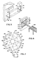
- Fig.5 is a perspective view illustrating another example of curtain system.
- Fig.6 is a perspective view illustrating another example of the light curtain system.
- Fig.7 is a plan view of a light curtain system illustrating one embodiment method of operation.
- Figs. 1-3 illustrate an example of a light curtain system 10.
- the light curtain system is comprised of three light curtain segments 12, 14 and 16.
- the segments are positioned so that their detection planes 18.20 are aligned in a U-shaped orientation with a zone of protection defined between the operator and front and side portions of the machine.
- the machine is a punch press 22, and it is understood that the U-shaped protection zone of this example will have application for other machinery.
- the light curtain segments are comprised of respective transmitter heads 24,26,28 and receiver heads 30,32,34.
- the transmitter head of the typical segment 12 includes an elongate housing 36 which carries a plurality of light sources, preferably light-emitting diodes (LEDs) (not shown).
- the LEDs emit pulses of infrared light responsive to the control circuit 38 of Fig.3, which is contained in a box 40.
- the receiver head 30 of the typical segment 12 includes an elongate housing 44 which carries a plurality of phototransistors (PTs) (not shown), which are equal in number to the number of light transmitting LEDs in the segment. Each PT is associated with the LED of a respective channel.
- the transmitter and receiver heads are oriented at the workplace so that the PTs are substantially in optical alignment with the light beams from the LEDs.
- the schematic of Fig.2 illustrates the means for flexibly interconnecting the light curtain segments with the control circuit 38.
- the transmitter control and power lines lead from the circuit within box 40 through a cable 45 to the first transmitter head 24 for feeding the LEDs which it contains.
- the control and power supply lines continue through a flexible cable 46 which interconnects with second transmitter head 26.
- the lines continue through a second flexible cable 48 which connects with third transmitter head 28.
- the receiver control and power lines lead from the circuit through another cable 50 into the first receiver head 30 where the lines connect with the first set of PTs.
- the lines continue through a flexible cable 50 which interconnects with second receiver head 32, and then through a third cable 52 which interconnects with third receiver head 34.
- the transmitter heads are located atop the receiver heads with the light beams transmitted vertically downwardly.
- the heads could be reversed with the light beams transmitted upwardly.
- the flexible cables interconnecting the transmitter and receiver heads may be of the plug-in type so that the installation can be tailored to a particular workplace environment.
- the light curtain components can be shipped to the end user who can then mount and couple together the segments in the desired angular orientation to match the configuration of the particular machine or equipment around which the protection zone is to be established.
- FIG. 3 illustrates the major components of control circuit 38 in block diagram form.
- the circuit includes a power supply 54, logic circuit 56, relay operate/check circuit 58, relay output circuit 60, interface circuit 62 which interconnects the logic circuit with the transmitter heads 24-28, and amplifier interface circuit 66 which interconnects the logic circuit with receiver heads 30-34.
- the lines 68 represent the paths of the light beams which project across the detection planes from the transmitter LEDs to the receiver PTs. Details of the control circuit components and mode of operation of the circuit can advantageously be as described in United States patent no. 5,015,840, which is assigned to the assignee of the present invention.
- control circuit 38 With control circuit 38 in operation, the LEDs in each transmitter head strobe infrared light beams along parallel channels to the respective PTs in the receiver heads.
- the logic circuit operates as described in patent 5,015,840 to activate the LEDs in sequence and strobe the beams so that they are addressed exclusively for given channels.
- the circuit senses that the beam is not present at the PTs in those channels at the proper time in the sequence. The circuit then generates a shutdown signal which is directed to the relay drivers depicted by the box 70. The relays in turn operate either to shut the machinery down, activate an alarm, or otherwise safeguard the area as required by the particular installation.
- Fig.4 illustrates another example providing a system 70 having two light curtain segments 72 and 74 arranged in an L-shaped angular orientation.
- the segments are comprised of respective transmitter heads 76,78 and receiver heads 80,82.
- the transmitter heads include housings which supports LEDs and focusing lenses. not shown. arrayed along linear paths.
- the receiver heads include housings which support PTs which correspond to the LEDs of the opposing transmitter heads.
- Brackets 84,86 are provided on the housing ends for mounting the segments in the desired orientation. Cables 88,90 connect the input ends of the respective transmitter and receivers heads to the controller an power supply circuit in box 92.
- Flexible plug-in cables 94.96 connect the respective transmitter and receiver heads together to operate in the circuit.
- FIG. 5 illustrates in perspective view one specific application of the L-shaped orientation of the two segment light curtain system of FIG. 4.
- the first segment 72 comprising transmitter head 80 and receiver head 76 is mounted so that its detection plane is positioned upright between the machinery, shown as a punch press, with the operator standing in front.
- the second segment 74 is mounted with transmitter head 82 and receiver head 78 horizontal so that its detection plane extends toward the machinery from the lower edge of the detection plane of the first segment.
- the operator is protected by the vertical detection plane of the first segment should the operator's hand or any other object penetrate the plane. Additional protection is provided by the horizontal plane of the second segment should the operator attempt to position his or her body between the vertical plane and the machinery.
- This combination has particular application in those cases where the operator may attempt to circumvent the protection of the vertical plane in an effort to increase productivity. such as by attempting to feed work pieces at a greater rate through the machine.
- Fig.6 illustrates another example providing a system 98 with two light curtain segments 100 and 102 arranged in a rectangular or "picture frame" orientation in which the light beam channels of the two segments are substantially orthogonal to one another, although the channels could be oriented at an acute angle.
- the system of this example is particularly adapted for applications in which sets of beams are deactivated to permit expected penetration through the detection planes of tooling, work pieces or other objects.
- the application for the illustrated example is a metal forming machine 104 in which a formed metal work piece 106 is moved out from an opening in the machine through the detection plane and onto a conveyor 108.
- First light curtain segment 100 is comprised of respective transmitter and receiver heads 110 and 112 which are mounted upright on opposite sides of the machine opening, with the light beam channels extending horizontally to form one detection plane.
- the second light curtain 5 segment 102 has its transmitter and receiver heads 114 and 116 mounted horizontally across the top and bottom sides of the machine opening with the light beam channels extending vertically.
- the detection planes of the two segments can be closely spaced apart, although this is not critical.
- a controller and power supply circuit not shown. similar to that described for the example of Figs. 1-3 is provided, with the respective transmitter and receiver heads connected through flexible cables, also not shown.
- the group of horizontal light beam channels of the first segment 100 which would otherwise cross the vertical height of the work piece are selectively deactivated by an appropriate setting of the control circuit.
- the group of vertical channels of the second segment 102 which would otherwise cross the horizontal width of the work piece are selectively deactivated in the circuit.
- the remaining area of the detection planes outside the entry area are not masked off and remain active for detecting any unintended intrusion of the operator's hand or other object.
- the overlapping beams in the vertical channels of the second segment remain active to protect that part of the zone.
- portions of the beams of the vertical channels are masked off by the work piece, that area remains protected by the overlapping horizontal channels of the first segment.
- Fig.7 illustrates another example providing a light curtain system 118 having transmitter and receiver heads arrayed about a common center 119 so that their light beams substantially overlap and form a detection zone about the center.
- the system includes a plurality, shown as four, of light beam segments 120-126 which comprise respective transmitter heads 128-134 and receiver heads 136-142.
- the transmitter and receiver heads are positioned as chords of a circle, with the transmitter heads on one side of the circle and the receiver heads aligned on the opposing side.
- the heads could be arrayed about an oval or other path about the common center.
- Fig.7 which can be used with the preferred embodiment of the operating method box 144 encloses a controller and power supply circuit, which preferably is similar to that described for tne embodiment of FIGS. 1-3.
- the circuit connects through a cable 146 with first transmitter head 128, and the remaining transmitter heads are interconnected by flexible plug-in cables 148-152.
- Cable 154 from the control circuit connects with the first receiver head 136, and the remaining receiver heads are interconnected through flexible plug-in cables 156-160.
- the control lines in the cables are arranged so that the transmitter and receiver heads which are mounted diametrically opposite each other operate together as a single light curtain segment. As shown in FIG. 7, the paths of the light curtains from the four segments intersect over the common center, with the circle shown by the broken line 162 forming a complete protected zone. The size of the protected zone would vary depending upon the width of the light curtains of each segment.
Landscapes
- Physics & Mathematics (AREA)
- Life Sciences & Earth Sciences (AREA)
- General Life Sciences & Earth Sciences (AREA)
- General Physics & Mathematics (AREA)
- Geophysics (AREA)
- Presses And Accessory Devices Thereof (AREA)
- Geophysics And Detection Of Objects (AREA)
- Burglar Alarm Systems (AREA)
Description
- This invention relates in general to a method of operating a light curtain of the type which detects the intrusion of human limbs or other objects into a protected zone for triggering alarms, shutting off machinery or otherwise responding to safeguard the zone.
- Light curtains are commonly employed in a variety of industrial applications to detect the intrusion of objects, such as hands or feet of personnel, into or around a prescribed area or zone of protection. Typical applications for light curtains include provide operator protection around machinery such punch presses, brakes, molding machines, automatic assembly equipment, coil winding machinery, robot operation, casting operations and the like. Conventional light curtain systems employ invisible pulsed infrared light beams which project across a plane along the zone to be protected. Unintended intrusion of the light beams by an object, such as the operator's hand, is sensed so that a control circuit triggers a warning signal, shuts the machinery down, or otherwise safeguards the area.
- Heretofore light curtain systems have been provided with transmitter and receiver heads arranged to pulse the beams across a single plane. The heads are typically mounted so that the plane is positioned between the human operator and the machine, such as in the front of a punch press. Additional light curtain systems with separate transmitter and receiver heads are required where it is desired to provide protection to other areas of the machine, such as along either or both sides. Because light curtain systems are expensive, this leads to increased cost of the installation.
- In certain cases it has been found that machine operators, in an effort to increase their productivity, attempt to foil the protection of the light curtains. For example, in the case of a single light curtain projected in a vertical plane between the operator and machine, the operator may attempt to reach under or around the plane of the curtain to feed the work pieces at a greater rate through the machine. With the light curtain system foiled in this manner, serious injury can result.
- Certain light curtains heretofore available have included control systems by which selected beams can be electronically disabled to permit the sensing area to be penetrated by expected tooling or work pieces. An example is a metal forming machine in which the formed work piece is fed from the machine out through an electronically masked-off portion of the sensing area. The remaining portion of the sensing area continues to operate for sensing intrusion of the operator's hands or other objects. However, in these conventional systems there are shadows of unprotected areas on opposite sides of the masked-off portion of the curtain. As a result, injury or damage can occur from intrusion of a hand or other object into the unprotected area.
- EP-A-0,369,386 discloses a photoelectric switch which includes a light-emitting section having a plurality of light-emitting elements arranged in a line, and a light-detecting section having a plurality of light-detecting elements arranged in a line in such a manner that the light-emitting elements confront with the light-detecting elements, thus providing a multi-optical path therebetween. Each light-emitting section and light-detecting section is formed by connecting a base unit to a relay unit and/or an end unit, whereby the length or configuration of the photoelectric switch can be readily changed by changing the number or configuration of the relay unit connected to the base unit.
- US-A-4,737,632 discloses an array assembly of a photoelectric touch panel in which each of at least a light emitting array and a light receiving array is formed in an integral shape, and the substrate of each array is molded by flexible material, whereby the work of molding and assembling can be simplified. Thus. each array can be bent to provide different light beams passing different directions.
- DE-A-2343096 discloses a light barrier for a metal press which consists of selenium cells onto which light beams are directed. The beams are divided into groups. Within each group the beams are parallel to one another, but the different groups are arranged at a right angle to one another. It is thus possible to eliminate the barrier effect of individual groups of beams so that only the required area round the workpiece is protected.
- Accordingly, it is the principal object of the present invention to provide an improved method of operating a light curtain system, by which a work area of other zone can be protected on a plurality of sides with greater flexibility in orientation of the different detection planes.
- Another object is to provide a method of operation of the type described by which the work place area can be protected in a manner which deters any attempts by the operator to foil the protection system.
- Another object is to provide a method of the type described in which portions of the sensing area can be selectively masked off for penetration of desired tooling or work pieces, and which does not create shadows of unprotected areas on opposite sides of the penetration area.
- According to an aspect of the present invention, there is provided a method of operating a light curtain system as specified in claim 1.
- The preferred embodiment can be used with a light curtain system which includes a plurality of light curtain segments, each of which includes spaced-apart transmitter and receiver heads. Light beams are sequentially pulsed from the transmitter heads across detection planes to the respective receiver heads. Connection means is provided for connecting the transmitter heads in series and also for connecting the receiver heads in series so that the concatenated segments operate in the manner of a single light curtain. The series- connected segments are positioned so that their detection planes are aligned in predetermined angular orientations which define a zone of protection. In another example employing an arrangement by which selected beams can be electronically masked off to permit the expected penetration of objects into an entry area of the plane. the segments are arranged so that shadows of unprotected areas are not cast on opposite sides of the entry area.
- The foregoing and additional objects and features of the invention will appear from the following specification in which one embodiment and several examples which only show some features of the invention have been set forth in conjunction with the accompanying drawings.
- Fig.1 is a perspective view illustrating an example of a light curtain system.
- Fig.2 is a schematic view illustrating the arrangement for connecting the light curtain segments for the system of Fig.1.
- Fig.3 is a schematic block diagram illustrating the major components of the electrical control system for the light curtain system of Figs 1 and 2.
- Fig.4 is a perspective view illustrating another example of light curtain system.
- Fig.5 is a perspective view illustrating another example of curtain system.
- Fig.6 is a perspective view illustrating another example of the light curtain system.
- Fig.7 is a plan view of a light curtain system illustrating one embodiment method of operation.
- In the drawings Figs. 1-3 illustrate an example of a
light curtain system 10. The light curtain system is comprised of threelight curtain segments - As best shown in Fig.2, the light curtain segments are comprised of
respective transmitter heads receiver heads typical segment 12 includes anelongate housing 36 which carries a plurality of light sources, preferably light-emitting diodes (LEDs) (not shown). The LEDs emit pulses of infrared light responsive to thecontrol circuit 38 of Fig.3, which is contained in abox 40. Collimating lenses, not shown, focus light beams from the LEDs into beams which project along predetermined paths orchannels 42 across the zone of the workplace which is to be protected. In the illustrated example the light beams are projected in spaced-apart parallel vertical channels. - The
receiver head 30 of thetypical segment 12 includes an elongate housing 44 which carries a plurality of phototransistors (PTs) (not shown), which are equal in number to the number of light transmitting LEDs in the segment. Each PT is associated with the LED of a respective channel. The transmitter and receiver heads are oriented at the workplace so that the PTs are substantially in optical alignment with the light beams from the LEDs. - While operation of the invention will be described in connection with the use of infrared light, it is understood that the invention contemplates the use of other radiant energy, for example near-infrared or visible light.
- The schematic of Fig.2 illustrates the means for flexibly interconnecting the light curtain segments with the
control circuit 38. The transmitter control and power lines lead from the circuit withinbox 40 through acable 45 to thefirst transmitter head 24 for feeding the LEDs which it contains. The control and power supply lines continue through aflexible cable 46 which interconnects withsecond transmitter head 26. The lines continue through a secondflexible cable 48 which connects withthird transmitter head 28. The receiver control and power lines lead from the circuit through anothercable 50 into thefirst receiver head 30 where the lines connect with the first set of PTs. The lines continue through aflexible cable 50 which interconnects withsecond receiver head 32, and then through a third cable 52 which interconnects withthird receiver head 34. In the illustrated example the transmitter heads are located atop the receiver heads with the light beams transmitted vertically downwardly. As desired, the heads could be reversed with the light beams transmitted upwardly. The flexible cables interconnecting the transmitter and receiver heads may be of the plug-in type so that the installation can be tailored to a particular workplace environment. For example, the light curtain components can be shipped to the end user who can then mount and couple together the segments in the desired angular orientation to match the configuration of the particular machine or equipment around which the protection zone is to be established. - FIG. 3 illustrates the major components of
control circuit 38 in block diagram form. The circuit includes apower supply 54,logic circuit 56, relay operate/check circuit 58, relay output circuit 60,interface circuit 62 which interconnects the logic circuit with the transmitter heads 24-28, andamplifier interface circuit 66 which interconnects the logic circuit with receiver heads 30-34. Thelines 68 represent the paths of the light beams which project across the detection planes from the transmitter LEDs to the receiver PTs. Details of the control circuit components and mode of operation of the circuit can advantageously be as described in United States patent no. 5,015,840, which is assigned to the assignee of the present invention. - With
control circuit 38 in operation, the LEDs in each transmitter head strobe infrared light beams along parallel channels to the respective PTs in the receiver heads. The logic circuit operates as described in patent 5,015,840 to activate the LEDs in sequence and strobe the beams so that they are addressed exclusively for given channels. When the beams in one or more channels are interrupted, such as due to intrusion of the operator's arm into the detection plane, the circuit senses that the beam is not present at the PTs in those channels at the proper time in the sequence. The circuit then generates a shutdown signal which is directed to the relay drivers depicted by thebox 70. The relays in turn operate either to shut the machinery down, activate an alarm, or otherwise safeguard the area as required by the particular installation. - Fig.4 illustrates another example providing a
system 70 having twolight curtain segments Brackets Cables 88,90 connect the input ends of the respective transmitter and receivers heads to the controller an power supply circuit inbox 92. Flexible plug-in cables 94.96 connect the respective transmitter and receiver heads together to operate in the circuit. - FIG. 5 illustrates in perspective view one specific application of the L-shaped orientation of the two segment light curtain system of FIG. 4. The
first segment 72 comprisingtransmitter head 80 andreceiver head 76 is mounted so that its detection plane is positioned upright between the machinery, shown as a punch press, with the operator standing in front. Thesecond segment 74 is mounted withtransmitter head 82 andreceiver head 78 horizontal so that its detection plane extends toward the machinery from the lower edge of the detection plane of the first segment. - In operation of the system of Fig.5, the operator is protected by the vertical detection plane of the first segment should the operator's hand or any other object penetrate the plane. Additional protection is provided by the horizontal plane of the second segment should the operator attempt to position his or her body between the vertical plane and the machinery. This combination has particular application in those cases where the operator may attempt to circumvent the protection of the vertical plane in an effort to increase productivity. such as by attempting to feed work pieces at a greater rate through the machine.
- Fig.6 illustrates another example providing a
system 98 with twolight curtain segments 100 and 102 arranged in a rectangular or "picture frame" orientation in which the light beam channels of the two segments are substantially orthogonal to one another, although the channels could be oriented at an acute angle. The system of this example is particularly adapted for applications in which sets of beams are deactivated to permit expected penetration through the detection planes of tooling, work pieces or other objects. The application for the illustrated example is ametal forming machine 104 in which a formedmetal work piece 106 is moved out from an opening in the machine through the detection plane and onto aconveyor 108. - First light curtain segment 100 is comprised of respective transmitter and receiver heads 110 and 112 which are mounted upright on opposite sides of the machine opening, with the light beam channels extending horizontally to form one detection plane. The second light curtain 5
segment 102 has its transmitter and receiver heads 114 and 116 mounted horizontally across the top and bottom sides of the machine opening with the light beam channels extending vertically. The detection planes of the two segments can be closely spaced apart, although this is not critical. A controller and power supply circuit, not shown. similar to that described for the example of Figs. 1-3 is provided, with the respective transmitter and receiver heads connected through flexible cables, also not shown. - In the operation of the example of Fig.6 the group of horizontal light beam channels of the first segment 100 which would otherwise cross the vertical height of the work piece are selectively deactivated by an appropriate setting of the control circuit. Similarly. the group of vertical channels of the
second segment 102 which would otherwise cross the horizontal width of the work piece are selectively deactivated in the circuit. This results in a rectangular entry area, which can be in the center of the machine opening, through which the formedmetal work piece 106 or other object can penetrate without triggering the detection circuit. At the same time, the remaining area of the detection planes outside the entry area are not masked off and remain active for detecting any unintended intrusion of the operator's hand or other object. Thus, while the portions of the horizontal channels of the first segment which lie between the work piece and transmitter and receiver heads are masked off by the work piece, the overlapping beams in the vertical channels of the second segment remain active to protect that part of the zone. Similarly, while portions of the beams of the vertical channels are masked off by the work piece, that area remains protected by the overlapping horizontal channels of the first segment. - Fig.7 illustrates another example providing a light curtain system 118 having transmitter and receiver heads arrayed about a common center 119 so that their light beams substantially overlap and form a detection zone about the center. The system includes a plurality, shown as four, of light beam segments 120-126 which comprise respective transmitter heads 128-134 and receiver heads 136-142. In the illustrated example the transmitter and receiver heads are positioned as chords of a circle, with the transmitter heads on one side of the circle and the receiver heads aligned on the opposing side. As required by the particular application, the heads could be arrayed about an oval or other path about the common center.
- In the example of Fig.7 which can be used with the preferred embodiment of the
operating method box 144 encloses a controller and power supply circuit, which preferably is similar to that described for tne embodiment of FIGS. 1-3. The circuit connects through a cable 146 withfirst transmitter head 128, and the remaining transmitter heads are interconnected by flexible plug-in cables 148-152. Cable 154 from the control circuit connects with thefirst receiver head 136, and the remaining receiver heads are interconnected through flexible plug-in cables 156-160. The control lines in the cables are arranged so that the transmitter and receiver heads which are mounted diametrically opposite each other operate together as a single light curtain segment. As shown in FIG. 7, the paths of the light curtains from the four segments intersect over the common center, with the circle shown by thebroken line 162 forming a complete protected zone. The size of the protected zone would vary depending upon the width of the light curtains of each segment.
Claims (1)
- A method of operating a light curtain system having at least three light curtain segments (12,14,16) with each segment including transmitter means (24-28) for strobing a plurality of light beams along channels to receiver means (30-24) for detecting the intrusion of human limbs or limbs or other objects into a common detection plane which defines a protected zone, comprising the steps of strobing light beams from the transmitter means (24-28) in the segments along corresponding channels which extend at given angles to one another and in the common detection plane so as to intersect one another, deactivating selected beams in each transmitter means along channels which substantially intersect an entry area into which an object is intended to penetrate, and enabling the receiver means to detect the intrusion of limbs or objects into any portion of the detection plane lying outside said entry area.
Applications Claiming Priority (2)
| Application Number | Priority Date | Filing Date | Title |
|---|---|---|---|
| US07/843,762 US5198661A (en) | 1992-02-28 | 1992-02-28 | Segmented light curtain system and method |
| US843762 | 1992-02-28 |
Publications (2)
| Publication Number | Publication Date |
|---|---|
| EP0562726A1 EP0562726A1 (en) | 1993-09-29 |
| EP0562726B1 true EP0562726B1 (en) | 1997-05-28 |
Family
ID=25290943
Family Applications (1)
| Application Number | Title | Priority Date | Filing Date |
|---|---|---|---|
| EP93301516A Revoked EP0562726B1 (en) | 1992-02-28 | 1993-02-26 | Segmented light curtain system and method |
Country Status (4)
| Country | Link |
|---|---|
| US (2) | US5198661A (en) |
| EP (1) | EP0562726B1 (en) |
| CA (1) | CA2090190C (en) |
| DE (1) | DE69310977T2 (en) |
Cited By (1)
| Publication number | Priority date | Publication date | Assignee | Title |
|---|---|---|---|---|
| DE102010007365A1 (en) * | 2010-02-10 | 2011-08-11 | Envipco Holding N.V. | Object i.e. article, capturing and detecting device for use in e.g. milling cutter, has control unit, evaluation unit and memory receiving signals output by image sensor and evaluating and identifying materials contained in object |
Families Citing this family (80)
| Publication number | Priority date | Publication date | Assignee | Title |
|---|---|---|---|---|
| US5408089A (en) * | 1993-09-02 | 1995-04-18 | White Storage & Retrieval Systems, Inc. | Object detection system with a plurality of detectors for moveable storage unit systems and work areas having exits |
| DE4334675A1 (en) * | 1993-10-12 | 1995-04-13 | Josef Femboeck | Device for monitoring areas of space |
| US5577733A (en) * | 1994-04-08 | 1996-11-26 | Downing; Dennis L. | Targeting system |
| US5469262A (en) * | 1994-07-12 | 1995-11-21 | Fairbanks Inc. | Dimension-measuring apparatus |
| FR2733849B1 (en) * | 1995-05-05 | 1997-07-04 | Sarl Scmd | ELECTROSENSITIVE ACCESS AND PRESENCE CONTROL DEVICE |
| US5848707A (en) * | 1996-02-16 | 1998-12-15 | Hill; Brian I. | Storage rack with position sensing |
| US5805288A (en) * | 1996-03-05 | 1998-09-08 | Laserscore, Inc. | Apparatus for detecting the presence and location of at least one object in a field |
| EP0808643B1 (en) * | 1996-05-21 | 2002-11-06 | MICROGATE S.r.l. | Optoelectronic device for measuring the ground contact time and position of a body within a preset region |
| JP3465263B2 (en) * | 1996-09-04 | 2003-11-10 | オムロン株式会社 | Operation control device |
| FR2757980B1 (en) * | 1996-12-26 | 1999-03-05 | Sarl Scmd | ELECTROSENSITIVE ACCESS CONTROL DEVICE |
| KR100563456B1 (en) * | 1997-04-14 | 2006-05-25 | 아시스트 신꼬, 인코포레이티드 | The self-transfer vehicle and its device |
| WO1998047645A1 (en) * | 1997-04-23 | 1998-10-29 | Sick Ag | Machine |
| DE59705191D1 (en) * | 1997-06-30 | 2001-12-06 | Cedes Ag Landquart | Photo eye or light curtain with alignment aid |
| US6147759A (en) * | 1998-02-04 | 2000-11-14 | Laserscore, Inc. | System for detecting the presence and location of at least one object in a field by using a divergent radiation source and an array of opposed plural detectors which rotate together around the field |
| JPH11306427A (en) * | 1998-04-24 | 1999-11-05 | Asahi Seiko Co Ltd | Disc ejection device with sampling detection |
| US6384402B1 (en) * | 1998-04-29 | 2002-05-07 | Automated Merchandising Systems | Optical vend-sensing system for control of vending machine |
| JPH11353986A (en) * | 1998-06-09 | 1999-12-24 | Keyence Corp | Controller for plural area sensors |
| JPH11354831A (en) * | 1998-06-10 | 1999-12-24 | Keyence Corp | Area sensor with optical axis having narrow angular characteristics |
| DE60041041D1 (en) | 1999-03-11 | 2009-01-22 | Omron Scientific Technologies Inc | MODULAR SWIVEL LIGHT BARRIER |
| US6166371A (en) * | 1999-04-30 | 2000-12-26 | Beckman Coulter, Inc. | Diffuse reflective light curtain system |
| US7042492B2 (en) | 1999-12-10 | 2006-05-09 | The Stanley Works | Automatic door assembly with video imaging device |
| EP1113214A1 (en) * | 1999-12-28 | 2001-07-04 | Infineon Technologies AG | Light curtain system for establishing a protective light curtain, tool and system for processing objects and method for loading/unloading a tool |
| GB2364773A (en) * | 2000-02-10 | 2002-02-06 | Rwl Consultants Ltd | Improvements In Or Relating To A Light Curtain |
| US6635862B2 (en) | 2000-03-10 | 2003-10-21 | Scientific Technologies Incorporated | Mixed architecture light curtain system |
| US6680469B2 (en) * | 2000-03-10 | 2004-01-20 | Scientific Technologies Incorporated | Segmented light curtain with keyed interfaces |
| ATE349713T1 (en) | 2000-05-26 | 2007-01-15 | Mark R Brent | PERIMETER MONITORING SYSTEM AND AUTOMATED CONTAINER |
| US6974948B1 (en) | 2000-05-26 | 2005-12-13 | Brent Mark R | Perimetric detection system |
| US6354716B1 (en) | 2000-08-04 | 2002-03-12 | Honeywell International Inc | Light curtain device |
| JP3788502B2 (en) * | 2000-08-11 | 2006-06-21 | オムロン株式会社 | Light curtain creation device |
| US6732014B2 (en) | 2001-02-27 | 2004-05-04 | Crane Co. | System for accomplishing product detection |
| US7286901B2 (en) | 2001-02-27 | 2007-10-23 | Crane Co. | Method and system for accomplishing product detection |
| DE10120940B4 (en) * | 2001-04-20 | 2017-12-14 | Fiessler Elektronik Gmbh & Co. Kg | Safety device for monitoring at least two adjoining planes by means of light barrier arrangements, in particular light curtains |
| US6778079B2 (en) * | 2001-05-16 | 2004-08-17 | Banner Engineering | Input/output methodology for control reliable interconnection of safety light curtains and other machine safety controls |
| JP4634658B2 (en) * | 2001-06-29 | 2011-02-16 | 株式会社キーエンス | Multi-optical axis photoelectric sensor and light projector and light receiver included therein |
| US8548625B2 (en) * | 2001-08-23 | 2013-10-01 | Crane Merchandising Systems, Inc. | Optical vend sensing system for product delivery detection |
| DE10143505B4 (en) * | 2001-09-05 | 2010-07-08 | Sick Ag | Safety procedure and optoelectronic sensor |
| JP4208535B2 (en) * | 2001-12-12 | 2009-01-14 | 株式会社キーエンス | Multi-optical axis photoelectric sensor and its fixture |
| US6710325B2 (en) | 2001-12-20 | 2004-03-23 | Dynapar Corporation | Light curtain mounting system wherein housing and mounting bracket include curved surfaces |
| DE10216122A1 (en) * | 2002-04-12 | 2003-10-30 | Sick Ag | object detection |
| JP4212970B2 (en) * | 2003-06-30 | 2009-01-21 | 株式会社キーエンス | Safety relay system |
| US6836329B1 (en) * | 2003-07-09 | 2004-12-28 | International Business Machines Corporation | Real time IR optical sensor |
| DE10360789B4 (en) * | 2003-12-23 | 2007-03-15 | Leuze Lumiflex Gmbh + Co. Kg | Device for monitoring a detection area on a work equipment |
| US7565222B2 (en) * | 2004-01-15 | 2009-07-21 | Fawn Engineering Corporation | Economical optical system to provide reasonable assurance of completed vend or vendible items from vending machines |
| GB2415499A (en) * | 2004-06-23 | 2005-12-28 | Canon Res Ct Europ Ltd | Apparatus and method for object shape detection |
| US7446302B2 (en) * | 2004-07-09 | 2008-11-04 | Automated Merchandising Systems, Inc. | Optical vend-sensing system for control of vending machine |
| GB2419297B (en) * | 2004-10-23 | 2009-06-03 | Michael Berner | Safety assembly |
| CN1828118B (en) * | 2005-03-01 | 2011-05-25 | 海德堡印刷机械股份公司 | Light barrier having separate output signals |
| IL167932A (en) * | 2005-04-10 | 2012-03-29 | Israel Aerospace Ind Ltd | Systems and methods for detecting the position of an object passing through optical screens |
| ITMI20051381A1 (en) * | 2005-07-20 | 2007-01-21 | Ecoassistenza S R L | SAFETY DEVICE FOR A FEEDING TAPE AND A PRESS INTENDED FOR THE COMPRESSION OF WASTE |
| US7573158B2 (en) * | 2005-08-29 | 2009-08-11 | Sunbeam Products, Inc. | Portable electrical appliance with object sensing assembly |
| US7329854B2 (en) * | 2005-09-26 | 2008-02-12 | Banner Engineering Corporation | System and method of connecting multiple safety light curtains |
| US7343062B1 (en) | 2006-01-17 | 2008-03-11 | Rockwell Automation Technologies, Inc. | Safety light curtain with MEMS |
| DE102006003954A1 (en) * | 2006-01-26 | 2007-08-02 | Sick Ag | light Curtain |
| DE102006042908B4 (en) * | 2006-04-07 | 2009-11-12 | Eads Deutschland Gmbh | Method for monitoring openings on the outer skin of aircraft against unauthorized intrusion of persons or property |
| US7439512B2 (en) * | 2006-06-26 | 2008-10-21 | Qualex Manufacturing Llc | Method and apparatus for detecting unsafe conditions |
| US8101917B2 (en) * | 2006-06-26 | 2012-01-24 | Qualex Manufacturing Llc | Method and apparatus for detecting unsafe conditions |
| CN101617354A (en) | 2006-12-12 | 2009-12-30 | 埃文斯和萨瑟兰计算机公司 | Be used for calibrating the system and method for the rgb light of single modulator projector |
| EP1978378B1 (en) * | 2007-03-21 | 2012-02-15 | Sick Ag | Optoelectronic sensor assembly |
| JP4979518B2 (en) * | 2007-09-05 | 2012-07-18 | 株式会社キーエンス | Intrusion detection device |
| US8358317B2 (en) | 2008-05-23 | 2013-01-22 | Evans & Sutherland Computer Corporation | System and method for displaying a planar image on a curved surface |
| US8702248B1 (en) | 2008-06-11 | 2014-04-22 | Evans & Sutherland Computer Corporation | Projection method for reducing interpixel gaps on a viewing surface |
| US8077378B1 (en) | 2008-11-12 | 2011-12-13 | Evans & Sutherland Computer Corporation | Calibration system and method for light modulation device |
| US8314393B2 (en) | 2008-12-23 | 2012-11-20 | Qualex Manufacturing, Lc | Method and apparatus for detecting unsafe conditions |
| DE102010009590A1 (en) * | 2010-02-26 | 2011-09-01 | Rheinisch-Westfälische Technische Hochschule Aachen | Sensor system and method for monitoring a room |
| EP2407261B1 (en) * | 2010-07-16 | 2016-04-20 | Primetals Technologies Austria GmbH | Method for automatic positioning a spout of a metallurgical container |
| EP2511737B1 (en) * | 2011-04-13 | 2021-09-15 | Rockwell Automation Switzerland GmbH | Modular light curtain and plug-in module therefor |
| US9641826B1 (en) | 2011-10-06 | 2017-05-02 | Evans & Sutherland Computer Corporation | System and method for displaying distant 3-D stereo on a dome surface |
| US8729455B2 (en) | 2012-03-22 | 2014-05-20 | Envipco Holding NV | Device for capturing and detecting of objects |
| EP2660629B1 (en) | 2012-05-02 | 2014-11-26 | Cedes Safety & Automation AG | Optical module and optical unit for a light curtain, and fabrication method |
| JP5924134B2 (en) * | 2012-05-30 | 2016-05-25 | セイコーエプソン株式会社 | Intrusion detection device, robot system, intrusion detection method, and intrusion detection program |
| US9517617B2 (en) * | 2012-10-17 | 2016-12-13 | M&R Printing Equipment, Inc. | Printing machine safety system |
| DE102013112119B4 (en) * | 2013-11-04 | 2020-08-27 | Sick Ag | Light curtain arrangement |
| AU2014402771B2 (en) * | 2014-08-08 | 2020-01-16 | Perceptimed, Inc. | Pill speed and position sensor |
| US9671523B2 (en) * | 2015-08-05 | 2017-06-06 | Banner Engineering Corp. | Field installable light curtain status module |
| US10459113B2 (en) * | 2015-11-20 | 2019-10-29 | Banner Engineering Corp. | User selectable remote programming for cascade-connected light curtains |
| EP3236295B8 (en) * | 2016-04-19 | 2021-08-25 | Leuze electronic GmbH + Co KG | Light curtain |
| JP7118080B2 (en) * | 2016-11-16 | 2022-08-15 | ウィンク・ロボティクス | Eyelash evaluation method and apparatus |
| US10591633B2 (en) | 2017-12-22 | 2020-03-17 | At&T Intellectual Property I, L.P. | Optical environmental filter with intrusion protection |
| DE102018200860A1 (en) * | 2018-01-19 | 2019-07-25 | Kuka Deutschland Gmbh | Monitoring a workspace of a robot assembly |
| US12276493B2 (en) | 2021-07-23 | 2025-04-15 | Markem-Imaje Corporation | Method and apparatus for characterizing objects using a light-emitting array |
Citations (1)
| Publication number | Priority date | Publication date | Assignee | Title |
|---|---|---|---|---|
| DE2343096A1 (en) * | 1973-08-27 | 1975-03-13 | Wolfgang Beer | Light barrier safety device for machine tools - has intersecting groups of light beams |
Family Cites Families (18)
| Publication number | Priority date | Publication date | Assignee | Title |
|---|---|---|---|---|
| US3181035A (en) * | 1962-01-12 | 1965-04-27 | American Brake Shoe Co | Electronic control circuit |
| US3805061A (en) * | 1973-04-23 | 1974-04-16 | Tyco Laboratories Inc | Object detecting apparatus |
| US4015122A (en) * | 1974-07-12 | 1977-03-29 | Rubinstein Walter M | Photo-electric object detection system |
| US4249074A (en) * | 1978-06-06 | 1981-02-03 | Xenex Corporation | Intrusion detector for press brake |
| US4266124A (en) * | 1979-08-10 | 1981-05-05 | Data Instruments, Inc. | Photoelectric object detector system |
| DE2939833C2 (en) * | 1979-10-01 | 1982-06-09 | Universal-Maschinenfabrik Dr. Rudolf Schieber Gmbh & Co Kg, 7081 Westhausen | Protective device for the movement space of the slide of a flat knitting machine |
| US4571498A (en) * | 1982-07-06 | 1986-02-18 | Hagan Engineering, Inc. | Apparatus for interrogating phototransistors and the like |
| SU1208396A1 (en) * | 1984-06-04 | 1986-01-30 | Андроповский авиационный технологический институт | Protective device of working zone |
| US4645920A (en) * | 1984-10-31 | 1987-02-24 | Carroll Touch, Inc. | Early fault detection in an opto-matrix touch input device |
| US4652205A (en) * | 1985-05-02 | 1987-03-24 | Robotic Vision Systems, Inc. | Robot cell safety system |
| JPH0337062Y2 (en) * | 1985-05-17 | 1991-08-06 | ||
| US4818866A (en) * | 1986-01-13 | 1989-04-04 | Data Instruments, Inc. | Intrusion detection system for operating industrial machines with variable sensitivity |
| JPS62267807A (en) * | 1986-05-16 | 1987-11-20 | Alps Electric Co Ltd | Remote controller for automobile |
| JPS63103142U (en) * | 1986-12-22 | 1988-07-04 | ||
| JPH0690900B2 (en) * | 1988-11-14 | 1994-11-14 | 株式会社キーエンス | Multi-axis photoelectric switch |
| US5107253A (en) * | 1989-11-13 | 1992-04-21 | Tektronix, Inc. | Stylus position detection system for optical touch panel |
| US5015840B1 (en) * | 1990-01-09 | 1995-04-11 | Scient Technologies Inc | Self-checking light curtain system and method of operation. |
| US5117221A (en) * | 1990-08-16 | 1992-05-26 | Bright Technologies, Inc. | Laser image projection system with safety means |
-
1992
- 1992-02-28 US US07/843,762 patent/US5198661A/en not_active Expired - Lifetime
- 1992-12-22 US US07/994,784 patent/US5281809A/en not_active Expired - Lifetime
-
1993
- 1993-02-23 CA CA002090190A patent/CA2090190C/en not_active Expired - Lifetime
- 1993-02-26 EP EP93301516A patent/EP0562726B1/en not_active Revoked
- 1993-02-26 DE DE69310977T patent/DE69310977T2/en not_active Revoked
Patent Citations (1)
| Publication number | Priority date | Publication date | Assignee | Title |
|---|---|---|---|---|
| DE2343096A1 (en) * | 1973-08-27 | 1975-03-13 | Wolfgang Beer | Light barrier safety device for machine tools - has intersecting groups of light beams |
Cited By (2)
| Publication number | Priority date | Publication date | Assignee | Title |
|---|---|---|---|---|
| DE102010007365A1 (en) * | 2010-02-10 | 2011-08-11 | Envipco Holding N.V. | Object i.e. article, capturing and detecting device for use in e.g. milling cutter, has control unit, evaluation unit and memory receiving signals output by image sensor and evaluating and identifying materials contained in object |
| DE102010007365B4 (en) * | 2010-02-10 | 2012-03-22 | Envipco Holding N.V. | Device for detecting and detecting objects |
Also Published As
| Publication number | Publication date |
|---|---|
| DE69310977T2 (en) | 1997-12-18 |
| CA2090190C (en) | 2000-08-22 |
| DE69310977D1 (en) | 1997-07-03 |
| EP0562726A1 (en) | 1993-09-29 |
| CA2090190A1 (en) | 1993-08-29 |
| US5281809A (en) | 1994-01-25 |
| US5198661A (en) | 1993-03-30 |
Similar Documents
| Publication | Publication Date | Title |
|---|---|---|
| US5281809A (en) | Method of operating light curtain with deactivated zone control | |
| EP1175579B1 (en) | Diffuse reflective light curtain system | |
| EP0598630B2 (en) | Light curtain system with individual beam indicators and method of operation | |
| EP0964324B1 (en) | Controller for plural area sensors | |
| US5393973A (en) | Optical sensing arrays employing misaligned squinted optical axes compared to aligned axes | |
| US9103931B2 (en) | Modular light curtain and optical unit for a light curtain | |
| US7485841B2 (en) | Multi-optical axis photoelectric sensor | |
| US6958465B2 (en) | Method for detecting objects and light barrier grid | |
| EP1161694B1 (en) | Modular articulated light curtain | |
| CA1109539A (en) | Touch sensitive computer input device | |
| JPH11345548A (en) | Method for displaying state of multi-optical-axis photoelectric switch and multi-optical-axis photoelectric switch | |
| GB2215454A (en) | Passive infrared security sensors | |
| JPH0423233B2 (en) | ||
| AU2002321087B2 (en) | Sensor arrangement for monitoring a spatial area | |
| US20030029992A1 (en) | Multi-beam photoelectric safeguard system | |
| US20170097626A1 (en) | Method for automated control of a machine component | |
| JPH02142924A (en) | Protective device for mechanical member elongated in long size | |
| EP1344973A2 (en) | Column for a photoelectric barrier provided with muting sensors | |
| EP3051320B1 (en) | Cascading of optical units of a light curtain | |
| YU16587A (en) | Device for perceiving stifled signal, transmitted at least from one transmitter, in place between transmitter and receiver | |
| EP1803989A1 (en) | Safety light barrier | |
| JP4079291B2 (en) | Expansion type multi-optical axis photoelectric switch | |
| JP2014022133A (en) | Sensing device and safety device using the same | |
| JPH06328393A (en) | Cutter | |
| JP5959674B2 (en) | Multi-axis photoelectric sensor |
Legal Events
| Date | Code | Title | Description |
|---|---|---|---|
| PUAI | Public reference made under article 153(3) epc to a published international application that has entered the european phase |
Free format text: ORIGINAL CODE: 0009012 |
|
| AK | Designated contracting states |
Kind code of ref document: A1 Designated state(s): DE FR GB IT |
|
| 17P | Request for examination filed |
Effective date: 19940312 |
|
| 17Q | First examination report despatched |
Effective date: 19941129 |
|
| GRAG | Despatch of communication of intention to grant |
Free format text: ORIGINAL CODE: EPIDOS AGRA |
|
| GRAH | Despatch of communication of intention to grant a patent |
Free format text: ORIGINAL CODE: EPIDOS IGRA |
|
| GRAH | Despatch of communication of intention to grant a patent |
Free format text: ORIGINAL CODE: EPIDOS IGRA |
|
| GRAA | (expected) grant |
Free format text: ORIGINAL CODE: 0009210 |
|
| AK | Designated contracting states |
Kind code of ref document: B1 Designated state(s): DE FR GB IT |
|
| PG25 | Lapsed in a contracting state [announced via postgrant information from national office to epo] |
Ref country code: IT Free format text: LAPSE BECAUSE OF FAILURE TO SUBMIT A TRANSLATION OF THE DESCRIPTION OR TO PAY THE FEE WITHIN THE PRE;WARNING: LAPSES OF ITALIAN PATENTS WITH EFFECTIVE DATE BEFORE 2007 MAY HAVE OCCURRED AT ANY TIME BEFORE 2007. THE CORRECT EFFECTIVE DATE MAY BE DIFFERENT FROM THE ONE RECORDED.SCRIBED TIME-LIMIT Effective date: 19970528 |
|
| RAP2 | Party data changed (patent owner data changed or rights of a patent transferred) |
Owner name: SCIENTIFIC TECHNOLOGIES INCORPORATED |
|
| REF | Corresponds to: |
Ref document number: 69310977 Country of ref document: DE Date of ref document: 19970703 |
|
| ET | Fr: translation filed | ||
| REG | Reference to a national code |
Ref country code: FR Ref legal event code: CA |
|
| PLBQ | Unpublished change to opponent data |
Free format text: ORIGINAL CODE: EPIDOS OPPO |
|
| PLBI | Opposition filed |
Free format text: ORIGINAL CODE: 0009260 |
|
| PLBF | Reply of patent proprietor to notice(s) of opposition |
Free format text: ORIGINAL CODE: EPIDOS OBSO |
|
| 26 | Opposition filed |
Opponent name: SICK AG Effective date: 19980227 |
|
| PLBF | Reply of patent proprietor to notice(s) of opposition |
Free format text: ORIGINAL CODE: EPIDOS OBSO |
|
| PLBF | Reply of patent proprietor to notice(s) of opposition |
Free format text: ORIGINAL CODE: EPIDOS OBSO |
|
| PGFP | Annual fee paid to national office [announced via postgrant information from national office to epo] |
Ref country code: GB Payment date: 19990203 Year of fee payment: 7 Ref country code: FR Payment date: 19990203 Year of fee payment: 7 |
|
| PGFP | Annual fee paid to national office [announced via postgrant information from national office to epo] |
Ref country code: DE Payment date: 19990204 Year of fee payment: 7 |
|
| RDAH | Patent revoked |
Free format text: ORIGINAL CODE: EPIDOS REVO |
|
| RDAG | Patent revoked |
Free format text: ORIGINAL CODE: 0009271 |
|
| STAA | Information on the status of an ep patent application or granted ep patent |
Free format text: STATUS: PATENT REVOKED |
|
| 27W | Patent revoked |
Effective date: 19991202 |
|
| GBPR | Gb: patent revoked under art. 102 of the ep convention designating the uk as contracting state |
Free format text: 991202 |
|
| PLAB | Opposition data, opponent's data or that of the opponent's representative modified |
Free format text: ORIGINAL CODE: 0009299OPPO |