EP0562710A2 - Low NOx formation burner apparatus and methods - Google Patents
Low NOx formation burner apparatus and methods Download PDFInfo
- Publication number
- EP0562710A2 EP0562710A2 EP93301134A EP93301134A EP0562710A2 EP 0562710 A2 EP0562710 A2 EP 0562710A2 EP 93301134 A EP93301134 A EP 93301134A EP 93301134 A EP93301134 A EP 93301134A EP 0562710 A2 EP0562710 A2 EP 0562710A2
- Authority
- EP
- European Patent Office
- Prior art keywords
- fuel gas
- air
- wall portion
- furnace
- primary
- Prior art date
- Legal status (The legal status is an assumption and is not a legal conclusion. Google has not performed a legal analysis and makes no representation as to the accuracy of the status listed.)
- Withdrawn
Links
Images

Classifications
-
- F—MECHANICAL ENGINEERING; LIGHTING; HEATING; WEAPONS; BLASTING
- F23—COMBUSTION APPARATUS; COMBUSTION PROCESSES
- F23D—BURNERS
- F23D14/00—Burners for combustion of a gas, e.g. of a gas stored under pressure as a liquid
- F23D14/02—Premix gas burners, i.e. in which gaseous fuel is mixed with combustion air upstream of the combustion zone
- F23D14/04—Premix gas burners, i.e. in which gaseous fuel is mixed with combustion air upstream of the combustion zone induction type, e.g. Bunsen burner
-
- F—MECHANICAL ENGINEERING; LIGHTING; HEATING; WEAPONS; BLASTING
- F23—COMBUSTION APPARATUS; COMBUSTION PROCESSES
- F23C—METHODS OR APPARATUS FOR COMBUSTION USING FLUID FUEL OR SOLID FUEL SUSPENDED IN A CARRIER GAS OR AIR
- F23C9/00—Combustion apparatus characterised by arrangements for returning combustion products or flue gases to the combustion chamber
- F23C9/006—Combustion apparatus characterised by arrangements for returning combustion products or flue gases to the combustion chamber the recirculation taking place in the combustion chamber
-
- F—MECHANICAL ENGINEERING; LIGHTING; HEATING; WEAPONS; BLASTING
- F23—COMBUSTION APPARATUS; COMBUSTION PROCESSES
- F23C—METHODS OR APPARATUS FOR COMBUSTION USING FLUID FUEL OR SOLID FUEL SUSPENDED IN A CARRIER GAS OR AIR
- F23C6/00—Combustion apparatus characterised by the combination of two or more combustion chambers or combustion zones, e.g. for staged combustion
- F23C6/04—Combustion apparatus characterised by the combination of two or more combustion chambers or combustion zones, e.g. for staged combustion in series connection
- F23C6/045—Combustion apparatus characterised by the combination of two or more combustion chambers or combustion zones, e.g. for staged combustion in series connection with staged combustion in a single enclosure
- F23C6/047—Combustion apparatus characterised by the combination of two or more combustion chambers or combustion zones, e.g. for staged combustion in series connection with staged combustion in a single enclosure with fuel supply in stages
-
- F—MECHANICAL ENGINEERING; LIGHTING; HEATING; WEAPONS; BLASTING
- F23—COMBUSTION APPARATUS; COMBUSTION PROCESSES
- F23D—BURNERS
- F23D14/00—Burners for combustion of a gas, e.g. of a gas stored under pressure as a liquid
-
- F—MECHANICAL ENGINEERING; LIGHTING; HEATING; WEAPONS; BLASTING
- F23—COMBUSTION APPARATUS; COMBUSTION PROCESSES
- F23D—BURNERS
- F23D14/00—Burners for combustion of a gas, e.g. of a gas stored under pressure as a liquid
- F23D14/46—Details, e.g. noise reduction means
- F23D14/48—Nozzles
-
- F—MECHANICAL ENGINEERING; LIGHTING; HEATING; WEAPONS; BLASTING
- F23—COMBUSTION APPARATUS; COMBUSTION PROCESSES
- F23D—BURNERS
- F23D14/00—Burners for combustion of a gas, e.g. of a gas stored under pressure as a liquid
- F23D14/46—Details, e.g. noise reduction means
- F23D14/62—Mixing devices; Mixing tubes
- F23D14/64—Mixing devices; Mixing tubes with injectors
-
- F—MECHANICAL ENGINEERING; LIGHTING; HEATING; WEAPONS; BLASTING
- F23—COMBUSTION APPARATUS; COMBUSTION PROCESSES
- F23C—METHODS OR APPARATUS FOR COMBUSTION USING FLUID FUEL OR SOLID FUEL SUSPENDED IN A CARRIER GAS OR AIR
- F23C2201/00—Staged combustion
- F23C2201/20—Burner staging
-
- F—MECHANICAL ENGINEERING; LIGHTING; HEATING; WEAPONS; BLASTING
- F23—COMBUSTION APPARATUS; COMBUSTION PROCESSES
- F23C—METHODS OR APPARATUS FOR COMBUSTION USING FLUID FUEL OR SOLID FUEL SUSPENDED IN A CARRIER GAS OR AIR
- F23C2201/00—Staged combustion
- F23C2201/30—Staged fuel supply
-
- F—MECHANICAL ENGINEERING; LIGHTING; HEATING; WEAPONS; BLASTING
- F23—COMBUSTION APPARATUS; COMBUSTION PROCESSES
- F23D—BURNERS
- F23D2203/00—Gaseous fuel burners
- F23D2203/007—Mixing tubes, air supply regulation
Definitions
- the present invention relates to low NO x formation burner apparatus and methods of burning fuel gas - air mixtures whereby flue gases having low NO x content are produced.
- a burner apparatus for discharging a mixture of fuel gas and air into a furnace wherein said mixture is burned and flue gases having low NO x content are formed therefrom, said apparatus comprising a refractory burner tile attached to said furnace, said tile having a base portion and a wall portion, the wall portion extending into said furnace, surrounding a central area of said base portion and having external sides which slant towards the central area of said base portion; means connected to said burner tile for mixing a portion of said fuel gas with said air and discharging the resulting primary fuel gas-air mixture into a primary burning zone in said furnace from within the space defined by the central area of said base portion and the interior of said wall portion of said burner tile; and at least one secondary fuel gas nozzle means positioned for discharging the remaining portion of said fuel gas adjacent to said external slanted sides of said wall portion whereby said fuel gas mixes with flue gases in said furnace and burns in a secondary burning zone therein.
- the invention also provides a method of discharging a mixture of fuel gas and air into a furnace wherein said mixture is burned and flue gases having a low NO x content are formed therefrom, said method comprising the steps of:-
- a mixture of fuel gas and air is discharged into a furnace wherein the mixture is burned and flue gases having low NO x content are formed therefrom.
- a low NO x formation burner apparatus 10 is sealingly attached to the bottom wall 12 of a furnace over an opening therein. While gas burner apparatus are commonly mounted vertically on the bottom wall of a furnace and fired upwardly as shown in the drawings, it is to be understood that the burner apparatus of the present invention can also be mounted horizontally or it can be mounted vertically and fired downwardly.
- the burner apparatus 10 comprising a housing 14 having a closed exterior end 16 and a substantially closed interior end 18, is attached to the furnace wall 12 by means of a flange 20 and a plurality of bolts 22 which extend through complementary openings in the flange 20 and the wall 12.
- a combustion air inlet connection 24 is attached to the housing 14, and a conventional air flow rate regulating damper 26 is connected to and disposed within the air inlet connection 24.
- the furnace wall 12 includes an internal layer of insulating material 28 attached thereto, and a burner tile 30, which includes a base portion 32 and a wall portion 34, formed of flame and heat resistant refractory material is attached to the interior end 18 of the housing 14.
- the exterior side 36 of the base portion 32 is positioned adjacent the end 18 of the housing 14, and the interior side 38 of the base portion 32 faces the interior of the furnace.
- the wall portion 34 of the burner tile 30 extends into the furnace and surrounds a central area 40, bounded by straight internal sides 41, of portion 34, the external sides 43 of which are slanted towards the interior of the wall portion 34.
- a central opening 42 Formed in the base portion 32 of burner tile 30 is a central opening 42, and the end 18 of the housing 14 includes an opening 44 which is complementary to the opening 42. Attached within the housing 14 over the opening 44 in the end 18 thereof is an internally threaded tubular fitting 46. Connected within the fitting 46 is a venturi aspirator tube 48 having a fuel gas and air inlet 50 at one end positioned within the interior of the housing 14 and a discharge nozzle 52 at the other end positioned within the space defined by the central area 40 and the internal sides 41 of the wall portion 34. As shown in Figure 1, the venturi aspirator tube 48 comprises a fuel gas and air inlet part 54 having converging sides and a discharge nozzle part 56 having diverging sides. The adjacent ends of the parts 54 and 56 are threadedly connected to the threaded portion of the fitting 46.
- a fuel gas jet forming nozzle 58 is positioned within the housing 14 to jet fuel gas into and through the venturi tube 48.
- the jet forming nozzle 58 is connected to a conduit 60 which passes through the end 16 of the housing 14 and is connected to a fuel has header 62 by means of a union 64.
- Also connected to the fuel gas header 62 by a union 66 are four conduits 68 which pass through the end 16 of the housing 14, extend through the interior of the housing 14 and pass through the end 18 thereof.
- the conduits 68 extend through complementary openings in the base portion 32 of the burner tile 30 and are connected to secondary fuel gas nozzles 70 spaced around the periphery of the wall portion 34 and are each positioned adjacent to the intersection of a side 43 thereof with the surface 38 of the base portion 32.
- the nozzles 70 function to discharge secondary fuel gas adjacent to the external slanted sides 43 of the wall portion 34.
- a primary portion of the fuel gas conducted to the header 62 is caused to flow by way of the conduit 60 to the jet forming nozzle 58.
- the remaining, secondary portion of the fuel gas is distributed substantially equally between the conduits 68 and secondary fuel gas nozzles 70.
- orifices can be included in the unions 64 and 66 as required.
- Fuel gas is introduced into the furnace to which the burner apparatus 10 is attached and burned therein at a flow rate which results in the desired heat release.
- a flow rate of air is introduced into the burner housing 14 by way of the connection 24 and flow regulating damper 26 such that the total flow rate of fuel gas introduced into the furnace results in a stoichiometric or greater than stoichiometric mixture.
- the rate of air is in the range of from about the stoichiometric rate to about 25% greater than the stoichiometric rate.
- the air flows from the atmosphere into the interior of the housing 14 by way of the conduit 24 and damper 26 disposed therein.
- primary fuel gas is jetted from the jet forming nozzle 58 into the venturi aspirating tube 48, which causes air within the housing 14 to be drawn into the venturi aspirating tube 48 wherein the fuel gas and air are mixed.
- the resulting primary fuel gas - air mixture is discharged by way of the discharge nozzle 52 of the venturi aspirating tube 48 into the space defined by the central area 40 of the base portion 32 and the interior of the wall portion 34 of the burner tile 30.
- the primary fuel gas - air mixture begins to burn in the aforementioned space and is discharged therefrom into a primary burning zone within the furnace wherein the mixture is burned and flue gases having low NO x content are formed therefrom.
- the remaining secondary portion of the fuel gas (shown by solid line arrows) is discharged by way of the nozzles 70 adjacent to the exterior slanted sides of the wall portion 36 and readily mixes with flue gases from the furnace (shown by dashed line arrows) and air remaining in the furnace.
- the discharge openings in the nozzles 70 are preferably configured to spread the secondary fuel gas over the exterior slanted sides of the wall portion 34 which also enhances the mixing of the secondary fuel gas with flue gases and air.
- the mixture of secondary fuel gas and flue gases is discharged into a secondary burning zone surrounding the primary zone wherein it is burned and flue gases having low NO x content are formed therefrom.
- the primary fuel gas is mixed with substantially all of the air, it contains excess air and burns at a relatively low temperature which reduces the amount of NO x produced in the flue gases.
- the secondary fuel gas is mixed with relatively cool flue gases prior to burning and it also burns at a relatively low temperature whereby low levels of NO x are produced in the flue gases therefrom.
- the flow rate of primary fuel gas discharged into the furnace is from about 30% to about 90%, preferably about 75%, of the total fuel gas flow rate conducted to the burner apparatus 10, and the flow rate of the secondary fuel gas discharged into the furnace is from about 10% to about 70%, preferably about 25%, of the total fuel gas flow rate.
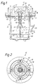
- the embodiment 80 shown in Figures 3 and 4 is substantially identical in structure and operation to the burner apparatus 10 described above except that instead of a single venturi aspirator tube 48, the burner apparatus 80 includes three venturi aspirator tubes 82, each comprising a converging inlet part 84 and a diverging discharge nozzle part 86.
- the interior end 88 of the housing 90 includes three threaded fittings 92 to which the parts 84 and 86 are threadedly connected attached over openings 94 therein, and the base portion 96 of a burner tile 98 includes complementary openings 100 therein for receiving the parts 86.
- a primary fuel gas jet forming nozzle 102 is positioned to jet primary fuel gas into each of the venturi aspirator tubes 82.
- the burner apparatus 80 (and the burner apparatus 10 described above) can optionally include a supplementary air pipe 99 which extends from within the housing 90 through the interior end 88 of the housing 90 and through the burner tile 98.
- a fitting 101 containing a changeable orifice for controlling the rate of air which flows through the pipe 99 can be connected to the inlet end of the pipe 99.
- the primary fuel gas - air mixtures discharged by the nozzles 85 of the parts 86 enter the space within the interior of the wall portion 104 of the burner tile 98 from where they are discharged to a primary burning zone within the furnace. Also, if the optional air pipe 99 is included, additional air enters the space within the wall (portion 104 and mixes with the fuel gas - air mixtures discharged from the nozzles 52.
- Secondary fuel gas is discharged adjacent to the exterior slanted sides 106 of the wall portion 104 by a plurality of secondary fuel gas nozzles 108.
- the secondary fuel gas mixes with flue gases in the furnace and burns in a secondary burning zone therein.
- the flue gases produced by the burner apparatus 80 are of low NO x content for the same reasons as those set forth above relating to the apparatus 10.
- the burner apparatus 10 and 80 can also be utilized in forced draft applications. That is, instead of mixing the primary fuel gas with atmospheric air in one or more venturi aspirator tubes, the primary fuel gas can be mixed with pressurized air in a conventional forced draft mixing apparatus, and the resultant primary fuel gas - air mixture can be conducted directly to the discharge nozzle 52 of the apparatus 10 or discharge nozzles 85 of the apparatus 80.
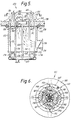
- FIGS 5 and 6 illustrate a third embodiment 120 which may be used in natural or forced draft applications, and like the burner apparatus 10 and 80 described above, produces flue gases having low NO x content.
- the burner apparatus 120 comprises a housing 122 having a closed exterior end 124 and an open interior end 126.
- the housing 122 is attached to a furnace wall 128 by means of a flange 130 attached to the housing 122 and a plurality of bolts 132 which extend through complementary openings in the flange 130 and wall 128.
- a combustion air inlet connection 134 is attached to the housing 122, and a conventional air flow rate regulating damper 136 is connected to and disposed within the air inlet connection 134.
- the furnace wall 128 includes an internal layer of insulating material 138 attached thereto, and the open end 126 of the housing 122 includes a refractory burner tile 140 attached thereto.
- the burner tile 140 comprises a substantially circular base portion 142 and a substantially circular wall portion 144.
- the external side of the base portion 142 is positioned adjacent the end 126 of the housing 122, and the internal side 146 of the base portion 142 faces the interior of the furnace to which the burner apparatus 120 is attached.
- the base portion 142 includes a central opening 148 therein, and the wall portion 144 extends into the furnace and surrounds the opening 148.
- the internal sides 150 of the wall portion 144 are spaced a distance from the periphery of the opening 148 whereby a ledge 152 is provided within the interior of the wall portion 144, and the external sides 154 of the wall portion 14 are slanted towards the opening 148.
- the internal sides 150 are also preferably slanted towards the opening 148.
- the apparatus 120 can also include a fixed blade swirler 166 positioned within the opening 148 by a support member 164 for causing all or a portion of the air flowing through the opening 148 to swirl.
- the nozzles 170 are spaced around the base portion 142 of the burner tile 140 outside the wall portion 14 thereof.
- the nozzles 170 are connected to conduits 172 which are connected to the fuel gas header 160 by unions 174, and are positioned to discharge secondary fuel gas adjacent to the external slanted sides 154 of the wall portion 144.
- the air flows through the housing 122 (shown by arrows formed of alternating dashes and dots), through the passage 148 in the base portion 142 of the burner tile 140 and into the interior of the wall portion 144 thereof.
- the fixed blade swirler 166 (if used) causes all or part of the air to swirl as it flows into and through the interior of the wall portion 144.
- the nozzles 156 direct primary fuel gas in directions generally tangential to the interior sides 150 of the wall portion 144 whereby the primary fuel gas is swirled around the interior sides of the wall portion 144 above the ledge 152.
- the slanted interior sides 150 of the wall portion 144 force the swirling primary fuel gas into contact with the air flowing through the interior of the wall portion 144.
- the primary fuel gas mixes with the air flowing through the opening 148 and the resulting primary fuel gas - air mixture begins to burn and is discharged from the interior of the wall portion 144 to a primary burning zone within the furnace.
- the primary fuel gas - air mixture contains cooling excess air and when it is burned in the primary burning zone, flue gases of low NO x content are produced.
- the resulting secondary fuel gas - flue gases air mixture is burned in a secondary burning zone whereby additional flue gases of low NO x content are formed.
- the rate of air introduced into the housing 122 and discharged by the burner 120 is preferably in the range of from about a stoichiometric rate to about 25% greater than such stoichiometric rate.
- the portion of fuel gas which is used as primary fuel is generally in the range of from about 10% to about 80% by volume of the total fuel gas discharged by the burner apparatus 120 into the furnace.
- the swirler 166 which is comprised of a plurality of fixed blades 167 ( Figure 6) can optionally be used to cause air flowing into the interior of the wall portion 144 of the burner tile 140 to swirl whereby it more readily mixes with the swirling primary fuel gas therein.
- Other alternative apparatus for enhancing mixture can be used with or substituted for the swirler 166, e.g., a cylindrical baffle which annularizes the flow of air.
- a burner apparatus 10 designed for a heat release of 2930 kilowatts by burning natural gas having a caloric value of 45474 joules/m3 is fired into a furnace.
- Pressurized fuel gas is supplied to the- manifold 62 of the burner 10 at a pressure of about 2.04 bar and at a rate of 85m3/hour.
- a 75% by volume portion of the fuel gas (63.75m3/hour) is used as primary fuel gas and is jetted into the venturi aspirator tube 48 by the nozzle 58 which results in air being drawn into the venturi aspirator tube 48 and mixing with the primary gas.
- the remaining secondary portion of the fuel gas i.e., 21.25m3/hour, is discharged into the furnace by the nozzles 70.
- the rate of air introduced into the housing 14 is controlled by means of the damper 26 such that the rate of air drawn into the venturi aspirator tube 48 is a substantially stoichiometric rate relative to the total fuel gas rate discharged into the furnace.
- the primary fuel gas - air mixture formed in the venturi aspirator tube 48 is discharged therefrom by the nozzle 52 positioned within the interior of the wall portion 34 of the burner tile 30 into a primary burning zone in the furnace wherein it is burned.
- the fuel gas discharged from the secondary fuel gas nozzles 64 adjacent to the wall portion 34 mixes with relatively cool flue gases and air remaining from the primary burning zone.
- the resulting mixture is burned in a secondary burning zone generally adjacent to and surrounding the primary burning zone in the furnace space.
- the flue gases formed have a low NO x content. That is, the flue gases withdrawn from the furnace have a NO x content of less than about 25 ppm.
- a burner apparatus 120 designed for a heat release of 2930 kilowatts by burning natural gas having a caloric value of 45474 joules/m3 is fired into a furnace space.
- Pressurized fuel-gas is supplied to the burner 150 at a pressure of about 30 PSIG and at a rate of 283.2m3/hour.
- a 15% by volume portion of the fuel gas (42.5m3/hour) is utilized as the primary fuel gas which is jetted into the space above the ledge 152 and adjacent the interior sides 150 of the wall portion 144 of the burner tile 140.
- the remaining secondary portion of the fuel gas, i.e., 240.7m3/hour is discharged adjacent to the exterior slanted sides 154 of the wall portion 140 by the secondary nozzles 168.
- the rate of air introduced into the housing 122 is controlled such that the rate of air discharged into the furnace is at least a substantially stoichiometric rate relative to the total fuel gas rate discharged therein.
- the air flows through the opening 148 of the burner tile 140 into the mixing zone defined by the wall portion 144 of the burner tile 140 and mixes with the primary fuel gas discharged therein by the nozzles 156.
- the resulting primary fuel gas - air mixture begins burning and is discharged into and burned in a primary burning zone in the furnace space.
- the secondary fuel gas discharged from the secondary fuel gas nozzles 170 mixes with flue gases from the furnace space and with air remaining therein and is burned in a secondary burning zone generally adjacent to and surrounding the primary burning zone in the furnace.
Landscapes
- Engineering & Computer Science (AREA)
- Chemical & Material Sciences (AREA)
- Combustion & Propulsion (AREA)
- Mechanical Engineering (AREA)
- General Engineering & Computer Science (AREA)
- Gas Burners (AREA)
- Pre-Mixing And Non-Premixing Gas Burner (AREA)
Abstract
Description
- The present invention relates to low NOx formation burner apparatus and methods of burning fuel gas - air mixtures whereby flue gases having low NOx content are produced.
- The environmental emission standards imposed by governmental authorities are continuously becoming more stringent. Such standards limit the quantities of gaseous pollutants such as oxides of nitrogen (NOx) and carbon monoxide which can be emitted into the atmosphere. As a result of the standards, improved burner designs have been developed which lower the production of NOx and other polluting gases. For example, methods and apparatus wherein fuel is burned in less than a stoichiometric concentration of oxygen intentionally to produce a reducing environment of CO and H₂ have been proposed. This concept has been utilized in stage air burner apparatus wherein the fuel is burned in a deficiency of air in a first zone producing a reducing environment that suppresses NOx formation, and the remaining portion of air is introduced into a second zone.
- Methods and apparatus have also been developed wherein all of the air and some of the fuel is burned in a first zone and the remaining fuel is burned in a second zone. In this staged fuel approach, an excess of air in the first zone acts as a diluent which lowers the temperature of the burning gases and thereby reduces the formation of NOx. Other methods and apparatus have been developed wherein flue gases are combined with fuel gas - air mixtures to dilute the mixtures and lower their combustion temperatures and the formation of NOx.
- While the prior art methods and burner apparatus for producing flue gases having low NOx contents have achieved varying degrees of success, there still remains a need for improvement in gas burner apparatus and methods of burning fuel gas whereby simple economical burner apparatus is utilized and low NOx content flue gases are produced.
- According to the present invention, there is provided a burner apparatus for discharging a mixture of fuel gas and air into a furnace wherein said mixture is burned and flue gases having low NOx content are formed therefrom, said apparatus comprising a refractory burner tile attached to said furnace, said tile having a base portion and a wall portion, the wall portion extending into said furnace, surrounding a central area of said base portion and having external sides which slant towards the central area of said base portion; means connected to said burner tile for mixing a portion of said fuel gas with said air and discharging the resulting primary fuel gas-air mixture into a primary burning zone in said furnace from within the space defined by the central area of said base portion and the interior of said wall portion of said burner tile; and at least one secondary fuel gas nozzle means positioned for discharging the remaining portion of said fuel gas adjacent to said external slanted sides of said wall portion whereby said fuel gas mixes with flue gases in said furnace and burns in a secondary burning zone therein.
- The invention also provides a method of discharging a mixture of fuel gas and air into a furnace wherein said mixture is burned and flue gases having a low NOx content are formed therefrom, said method comprising the steps of:-
- (a) mixing a portion of said fuel gas with said air to form a primary fuel gas - air mixture;
- (b) discharging said primary fuel gas - air mixture into a primary burning zone in said furnace from at least one location surrounded by a wall which extends into said furnace and has exterior sides which are slanted towards said location; and
- (c) discharging the remaining portion of said fuel gas from at least one location outside said wall adjacent to an exterior slanted side thereof whereby said fuel gas mixes with flue gases and air in said furnace space and is burned in a secondary burning zone therein.
- Using the apparatus and method of the invention, a mixture of fuel gas and air is discharged into a furnace wherein the mixture is burned and flue gases having low NOx content are formed therefrom.
- In order that the present invention may more readily be understood, the following description is given, merely by way of example, reference being made to the accompanying drawings in which:-
- Figure 1 is a side elevation in cross-section of one embodiment of the burner apparatus of the present invention attached to a furnace wall;
- Figure 2 is a cross-section taken along line 2-2 of Figure 1;
- Figure 3 is a side elevation in cross-section of a second embodiment;
- Figure 4 is a cross-section taken along line 4-4 of Figure 3;
- Figure 5 is a side elevation in cross-section of a third embodiment of burner apparatus of the present invention; and
- Figure 6 is a cross-section taken along line 6-6 of Figure 5.
- Referring now to Figures 1 and 2, a low NOx
formation burner apparatus 10 is sealingly attached to thebottom wall 12 of a furnace over an opening therein. While gas burner apparatus are commonly mounted vertically on the bottom wall of a furnace and fired upwardly as shown in the drawings, it is to be understood that the burner apparatus of the present invention can also be mounted horizontally or it can be mounted vertically and fired downwardly. - The
burner apparatus 10, comprising ahousing 14 having a closedexterior end 16 and a substantially closedinterior end 18, is attached to thefurnace wall 12 by means of aflange 20 and a plurality ofbolts 22 which extend through complementary openings in theflange 20 and thewall 12. A combustionair inlet connection 24 is attached to thehousing 14, and a conventional air flowrate regulating damper 26 is connected to and disposed within theair inlet connection 24. - The
furnace wall 12 includes an internal layer ofinsulating material 28 attached thereto, and aburner tile 30, which includes abase portion 32 and awall portion 34, formed of flame and heat resistant refractory material is attached to theinterior end 18 of thehousing 14. Theexterior side 36 of thebase portion 32 is positioned adjacent theend 18 of thehousing 14, and theinterior side 38 of thebase portion 32 faces the interior of the furnace. Thewall portion 34 of theburner tile 30 extends into the furnace and surrounds a central area 40, bounded by straightinternal sides 41, ofportion 34, theexternal sides 43 of which are slanted towards the interior of thewall portion 34. - Formed in the
base portion 32 ofburner tile 30 is acentral opening 42, and theend 18 of thehousing 14 includes an opening 44 which is complementary to the opening 42. Attached within thehousing 14 over the opening 44 in theend 18 thereof is an internally threadedtubular fitting 46. Connected within thefitting 46 is aventuri aspirator tube 48 having a fuel gas andair inlet 50 at one end positioned within the interior of thehousing 14 and a discharge nozzle 52 at the other end positioned within the space defined by the central area 40 and theinternal sides 41 of thewall portion 34. As shown in Figure 1, theventuri aspirator tube 48 comprises a fuel gas andair inlet part 54 having converging sides and adischarge nozzle part 56 having diverging sides. The adjacent ends of theparts fitting 46. - A fuel gas
jet forming nozzle 58 is positioned within thehousing 14 to jet fuel gas into and through theventuri tube 48. Thejet forming nozzle 58 is connected to aconduit 60 which passes through theend 16 of thehousing 14 and is connected to a fuel hasheader 62 by means of aunion 64. Also connected to thefuel gas header 62 by aunion 66 are fourconduits 68 which pass through theend 16 of thehousing 14, extend through the interior of thehousing 14 and pass through theend 18 thereof. Theconduits 68 extend through complementary openings in thebase portion 32 of theburner tile 30 and are connected to secondaryfuel gas nozzles 70 spaced around the periphery of thewall portion 34 and are each positioned adjacent to the intersection of aside 43 thereof with thesurface 38 of thebase portion 32. Thenozzles 70 function to discharge secondary fuel gas adjacent to the externalslanted sides 43 of thewall portion 34. - In operation a primary portion of the fuel gas conducted to the
header 62 is caused to flow by way of theconduit 60 to thejet forming nozzle 58. The remaining, secondary portion of the fuel gas is distributed substantially equally between theconduits 68 and secondaryfuel gas nozzles 70. In order to proportion the primary and secondary fuel gas and distribute the secondary fuel gas between theconduits 68 andnozzles 70, orifices can be included in theunions - Fuel gas is introduced into the furnace to which the
burner apparatus 10 is attached and burned therein at a flow rate which results in the desired heat release. A flow rate of air is introduced into theburner housing 14 by way of theconnection 24 and flow regulatingdamper 26 such that the total flow rate of fuel gas introduced into the furnace results in a stoichiometric or greater than stoichiometric mixture. Preferably, the rate of air is in the range of from about the stoichiometric rate to about 25% greater than the stoichiometric rate. - As shown in Figure 1 by arrows formed of alternating dashes and dots the air flows from the atmosphere into the interior of the
housing 14 by way of theconduit 24 anddamper 26 disposed therein. As shown by solid line arrows, primary fuel gas is jetted from thejet forming nozzle 58 into theventuri aspirating tube 48, which causes air within thehousing 14 to be drawn into theventuri aspirating tube 48 wherein the fuel gas and air are mixed. The resulting primary fuel gas - air mixture is discharged by way of the discharge nozzle 52 of theventuri aspirating tube 48 into the space defined by the central area 40 of thebase portion 32 and the interior of thewall portion 34 of theburner tile 30. The primary fuel gas - air mixture begins to burn in the aforementioned space and is discharged therefrom into a primary burning zone within the furnace wherein the mixture is burned and flue gases having low NOx content are formed therefrom. - The remaining secondary portion of the fuel gas (shown by solid line arrows) is discharged by way of the
nozzles 70 adjacent to the exterior slanted sides of thewall portion 36 and readily mixes with flue gases from the furnace (shown by dashed line arrows) and air remaining in the furnace. The discharge openings in thenozzles 70 are preferably configured to spread the secondary fuel gas over the exterior slanted sides of thewall portion 34 which also enhances the mixing of the secondary fuel gas with flue gases and air. The mixture of secondary fuel gas and flue gases is discharged into a secondary burning zone surrounding the primary zone wherein it is burned and flue gases having low NOx content are formed therefrom. - Because the primary fuel gas is mixed with substantially all of the air, it contains excess air and burns at a relatively low temperature which reduces the amount of NOx produced in the flue gases. The secondary fuel gas is mixed with relatively cool flue gases prior to burning and it also burns at a relatively low temperature whereby low levels of NOx are produced in the flue gases therefrom.
- The flow rate of primary fuel gas discharged into the furnace is from about 30% to about 90%, preferably about 75%, of the total fuel gas flow rate conducted to the
burner apparatus 10, and the flow rate of the secondary fuel gas discharged into the furnace is from about 10% to about 70%, preferably about 25%, of the total fuel gas flow rate. - The
embodiment 80 shown in Figures 3 and 4, is substantially identical in structure and operation to theburner apparatus 10 described above except that instead of a singleventuri aspirator tube 48, theburner apparatus 80 includes threeventuri aspirator tubes 82, each comprising a converginginlet part 84 and a divergingdischarge nozzle part 86. Theinterior end 88 of thehousing 90 includes three threadedfittings 92 to which theparts openings 94 therein, and thebase portion 96 of aburner tile 98 includescomplementary openings 100 therein for receiving theparts 86. A primary fuel gasjet forming nozzle 102 is positioned to jet primary fuel gas into each of theventuri aspirator tubes 82. Also, the burner apparatus 80 (and theburner apparatus 10 described above) can optionally include asupplementary air pipe 99 which extends from within thehousing 90 through theinterior end 88 of thehousing 90 and through theburner tile 98. A fitting 101 containing a changeable orifice for controlling the rate of air which flows through thepipe 99 can be connected to the inlet end of thepipe 99. - As described above in connection with the
apparatus 10, the primary fuel gas - air mixtures discharged by thenozzles 85 of theparts 86 enter the space within the interior of thewall portion 104 of theburner tile 98 from where they are discharged to a primary burning zone within the furnace. Also, if theoptional air pipe 99 is included, additional air enters the space within the wall (portion 104 and mixes with the fuel gas - air mixtures discharged from the nozzles 52. - Secondary fuel gas is discharged adjacent to the exterior slanted
sides 106 of thewall portion 104 by a plurality of secondaryfuel gas nozzles 108. The secondary fuel gas mixes with flue gases in the furnace and burns in a secondary burning zone therein. The flue gases produced by theburner apparatus 80 are of low NOx content for the same reasons as those set forth above relating to theapparatus 10. - The
burner apparatus apparatus 10 ordischarge nozzles 85 of theapparatus 80. - Figures 5 and 6 illustrate a
third embodiment 120 which may be used in natural or forced draft applications, and like theburner apparatus burner apparatus 120 comprises ahousing 122 having a closedexterior end 124 and an openinterior end 126. Thehousing 122 is attached to afurnace wall 128 by means of a flange 130 attached to thehousing 122 and a plurality ofbolts 132 which extend through complementary openings in the flange 130 andwall 128. A combustionair inlet connection 134 is attached to thehousing 122, and a conventional air flowrate regulating damper 136 is connected to and disposed within theair inlet connection 134. Thefurnace wall 128 includes an internal layer of insulatingmaterial 138 attached thereto, and theopen end 126 of thehousing 122 includes arefractory burner tile 140 attached thereto. - The
burner tile 140 comprises a substantiallycircular base portion 142 and a substantiallycircular wall portion 144. The external side of thebase portion 142 is positioned adjacent theend 126 of thehousing 122, and theinternal side 146 of thebase portion 142 faces the interior of the furnace to which theburner apparatus 120 is attached. Thebase portion 142 includes acentral opening 148 therein, and thewall portion 144 extends into the furnace and surrounds theopening 148. Theinternal sides 150 of thewall portion 144 are spaced a distance from the periphery of theopening 148 whereby aledge 152 is provided within the interior of thewall portion 144, and theexternal sides 154 of thewall portion 14 are slanted towards theopening 148. Theinternal sides 150 are also preferably slanted towards theopening 148. - Four primary fuel
gas discharge nozzles 156 are positioned within the interior of thewall portion 144 of theburner tile 140 adjacent theinterior sides 150 thereof and theledge 152 therein. Thenozzles 156 are connected toconduits 158 which pass through thebase portion 142 of theburner tile 140 and through theends housing 122. Theconduits 158 are connected to a pressurizedfuel gas header 160 byunions 162. Theapparatus 120 can also include a fixedblade swirler 166 positioned within theopening 148 by asupport member 164 for causing all or a portion of the air flowing through theopening 148 to swirl. - Four secondary
fuel gas nozzles 170 are spaced around thebase portion 142 of theburner tile 140 outside thewall portion 14 thereof. Thenozzles 170 are connected toconduits 172 which are connected to thefuel gas header 160 byunions 174, and are positioned to discharge secondary fuel gas adjacent to the externalslanted sides 154 of thewall portion 144. - In operation of the
burner apparatus 120, the air flows through the housing 122 (shown by arrows formed of alternating dashes and dots), through thepassage 148 in thebase portion 142 of theburner tile 140 and into the interior of thewall portion 144 thereof. As mentioned, the fixed blade swirler 166 (if used) causes all or part of the air to swirl as it flows into and through the interior of thewall portion 144. Thenozzles 156 direct primary fuel gas in directions generally tangential to the interior sides 150 of thewall portion 144 whereby the primary fuel gas is swirled around the interior sides of thewall portion 144 above theledge 152. The slantedinterior sides 150 of thewall portion 144 force the swirling primary fuel gas into contact with the air flowing through the interior of thewall portion 144. As a result, the primary fuel gas mixes with the air flowing through theopening 148 and the resulting primary fuel gas - air mixture begins to burn and is discharged from the interior of thewall portion 144 to a primary burning zone within the furnace. The primary fuel gas - air mixture contains cooling excess air and when it is burned in the primary burning zone, flue gases of low NOx content are produced. - Secondary fuel gas id discharged from the
nozzles 170 adjacent to the exterior slantedsides 154 of thewall portion 144 of theburner tile 140 and readily mixes with flue gases (shown by the dashed line arrows) and air remaining in the furnace. The resulting secondary fuel gas - flue gases air mixture is burned in a secondary burning zone whereby additional flue gases of low NOx content are formed. - The rate of air introduced into the
housing 122 and discharged by theburner 120 is preferably in the range of from about a stoichiometric rate to about 25% greater than such stoichiometric rate. The portion of fuel gas which is used as primary fuel is generally in the range of from about 10% to about 80% by volume of the total fuel gas discharged by theburner apparatus 120 into the furnace. - As mentioned, the
swirler 166 which is comprised of a plurality of fixed blades 167 (Figure 6) can optionally be used to cause air flowing into the interior of thewall portion 144 of theburner tile 140 to swirl whereby it more readily mixes with the swirling primary fuel gas therein. Other alternative apparatus for enhancing mixture can be used with or substituted for theswirler 166, e.g., a cylindrical baffle which annularizes the flow of air. - In order to further illustrate the low NOx formation burner apparatus and methods of the present invention, the following examples are given.
- A
burner apparatus 10 designed for a heat release of 2930 kilowatts by burning natural gas having a caloric value of 45474 joules/m³ is fired into a furnace. - Pressurized fuel gas is supplied to the-
manifold 62 of theburner 10 at a pressure of about 2.04 bar and at a rate of 85m³/hour. A 75% by volume portion of the fuel gas (63.75m³/hour) is used as primary fuel gas and is jetted into theventuri aspirator tube 48 by thenozzle 58 which results in air being drawn into theventuri aspirator tube 48 and mixing with the primary gas. The remaining secondary portion of the fuel gas, i.e., 21.25m³/hour, is discharged into the furnace by thenozzles 70. - The rate of air introduced into the
housing 14 is controlled by means of thedamper 26 such that the rate of air drawn into theventuri aspirator tube 48 is a substantially stoichiometric rate relative to the total fuel gas rate discharged into the furnace. - The primary fuel gas - air mixture formed in the
venturi aspirator tube 48 is discharged therefrom by the nozzle 52 positioned within the interior of thewall portion 34 of theburner tile 30 into a primary burning zone in the furnace wherein it is burned. - The fuel gas discharged from the secondary
fuel gas nozzles 64 adjacent to thewall portion 34 mixes with relatively cool flue gases and air remaining from the primary burning zone. The resulting mixture is burned in a secondary burning zone generally adjacent to and surrounding the primary burning zone in the furnace space. - Because of the dilution of the primary fuel gas with excess air and the dilution of the secondary fuel gas with flue gases, relatively low temperature burning results whereby the flue gases formed have a low NOx content. That is, the flue gases withdrawn from the furnace have a NOx content of less than about 25 ppm.
- A
burner apparatus 120 designed for a heat release of 2930 kilowatts by burning natural gas having a caloric value of 45474 joules/m³ is fired into a furnace space. - Pressurized fuel-gas is supplied to the
burner 150 at a pressure of about 30 PSIG and at a rate of 283.2m³/hour. A 15% by volume portion of the fuel gas (42.5m³/hour) is utilized as the primary fuel gas which is jetted into the space above theledge 152 and adjacent theinterior sides 150 of thewall portion 144 of theburner tile 140. The remaining secondary portion of the fuel gas, i.e., 240.7m³/hour is discharged adjacent to the exterior slantedsides 154 of thewall portion 140 by the secondary nozzles 168. - The rate of air introduced into the
housing 122 is controlled such that the rate of air discharged into the furnace is at least a substantially stoichiometric rate relative to the total fuel gas rate discharged therein. - The air flows through the
opening 148 of theburner tile 140 into the mixing zone defined by thewall portion 144 of theburner tile 140 and mixes with the primary fuel gas discharged therein by thenozzles 156. The resulting primary fuel gas - air mixture begins burning and is discharged into and burned in a primary burning zone in the furnace space. - The secondary fuel gas discharged from the secondary
fuel gas nozzles 170 mixes with flue gases from the furnace space and with air remaining therein and is burned in a secondary burning zone generally adjacent to and surrounding the primary burning zone in the furnace. - Because of the dilution of the primary fuel gas with excess air and the secondary fuel gas with flue gases, relatively low temperature burning results whereby the flue gases formed in and withdrawn from the furnace have a NOx content of less than about 25 ppm.
Claims (14)
- Burner apparatus for discharging a mixture of fuel gas and air into a furnace wherein said mixture is burned and flue gases having low NOx content are formed therefrom, said apparatus comprising:-
a refractory burner tile (30,98,140) attached to said furnace, said tile having a base portion (32,96,142) and a wall portion (34,104,144), the wall portion extending into said furnace, surrounding a central area (40) of said base portion and having external sides (43,106,154) which slant towards the central area of said base portion;
means (48,82,148) connected to said burner tile for mixing a portion of said fuel gas with said air and discharging the resulting primary fuel gas-air mixture into a primary burning zone in said furnace from within the space defined by the central area (40) of said base portion and the interior (41,150) of said wall portion of said burner tile; and
at least one secondary fuel gas nozzle &70,108,170) means positioned for discharging the remaining portion of said fuel gas adjacent to said external slanted sides (43,106,154) of said wall portion whereby said fuel gas mixes with flue gases in said furnace and burns in a secondary burning zone therein. - Apparatus according to claim 1, wherein said means for mixing primary fuel gas with said air and discharging the resulting mixture into said furnace comprise:-
said burner tile including at least one passage (42,100) formed in said base portion thereof extending from the exterior of said burner tile into the space defined by the central area (40) of said base portion and the interior of said wall portion;
venturi aspirator means (48,82) having a fuel gas and air inlet (50) at one end and a fuel gas - air mixture discharge nozzle (52,85) at the other end, said venturi aspirator means being disposed within said passage in said base portion of said burner tile with said discharge nozzle thereof positioned within said space defined by the central area of said base portion and said wall portion of said burner tile and the fuel gas and air inlet thereof positioned exterior of said burner tile; and
a fuel gas jet (58,102) forming nozzle adapted to be connected to a source of fuel gas positioned to jet primary fuel gas into said venturi means by way of the inlet end thereof whereby air is drawn into said venturi means and mixes with said primary fuel gas. - Apparatus according to claim 2, wherein said base portion of said burner tile includes two or more of said passages formed therein with venturi aspirator means disposed in each passage and a fuel gas jet forming nozzle positioned to jet primary fuel gas into each venturi aspirator means.
- Apparatus according to claim 1, wherein said means for mixing primary fuel gas with said air and discharging the resulting mixture into said furnace comprising:-
at least one passage (148) formed in said base portion of said burner tile extending from the exterior of said burner tile into the space defined by the central area (40) of said base portion (142) and the interior of said wall portion (144), said opening being smaller than said central area whereby a ledge (152) is formed around said opening within the interior of said wall portion;
means (134,136) for discharging said air through said opening attached to said burner tile; and
at least one primary fuel gas nozzle means (156) positioned to discharge primary fuel gas adjacent to the interior sides (150) of said wall portion and adjacent to said ledge whereby said primary fuel gas is swirled within said wall portion and mixed with said air. - Apparatus according to claim 4, wherein the interior sides of said wall portion of said burner tile are slanted towards said opening.
- Apparatus according to any preceding claim, which further comprises:
a housing (14,90) attached to the exterior of said burner tile and enclosing said venturi aspirator means and said fuel gas jet forming nozzle; and
means (24,26) for introducing a regulated rate of air into said housing attached thereto. - Apparatus according to any preceding claim, wherein said secondary fuel gas nozzle means (70,108,170) for discharging the remaining portion of said fuel gas is positioned outside said wall portion adjacent the intersection of said external slanted side of said wall portion with the surface of said base portion.
- A method of discharging a mixture of fuel gas and air into a furnace wherein said mixture is burned and flue gases having a low NOx content are formed therefrom, said method comprising the steps of:-(a) mixing a portion of said fuel gas with said air to form a primary fuel gas - air mixture;(b) discharging said primary fuel gas - air mixture into a primary burning zone in said furnace from at least one location surrounded by a wall which extends into said furnace and has exterior sides which are slanted towards said location; and(c) discharging the remaining portion of said fuel gas from at least one location outside said wall adjacent to an exterior slanted side thereof whereby said fuel gas mixes with flue gases and air in said furnace space and is burned in a secondary burning zone therein.
- A method according to claim 8, wherein said mixture of fuel gas and air discharged into said furnace is a substantially stoichiometric mixture.
- A method according to claim 8 or 9, wherein said portion of said fuel gas used to form said primary fuel gas - air mixture in accordance with step (a) is in the range of from about 10% to about 90% by volume of the total fuel gas discharged into said furnace space.
- A method according to claim 8, 9 or 10, wherein said primary fuel gas - air mixture is formed in accordance with step (a) by jetting said primary fuel gas into one end of at least one venturi aspirator tube having a discharge nozzle at the other end positioned at said location whereby said air is drawn into said venturi aspirator tube and mixed with said primary fuel therein.
- A method according to claim 8, wherein said primary fuel gas - air mixture is formed by discharging said air into said furnace at said location surrounded by said wall portion and discharging said primary fuel gas from at least one fuel gas nozzle adjacent to the interior sides of said wall portion whereby said fuel gas is swirled therein and mixed with said air.
- A method according to any one of claims 8 to 12, wherein said remaining portion of said fuel gas is discharged adjacent to the exterior slanted sides of said wall portion from a plurality of locations outside of said wall portion.
- A method according to claim 13, wherein said primary fuel gas is discharged adjacent to the interior sides of said wall portion from a plurality of fuel gas nozzles.
Applications Claiming Priority (2)
| Application Number | Priority Date | Filing Date | Title |
|---|---|---|---|
| US07/858,663 US5195884A (en) | 1992-03-27 | 1992-03-27 | Low NOx formation burner apparatus and methods |
| US858663 | 1992-03-27 |
Publications (2)
| Publication Number | Publication Date |
|---|---|
| EP0562710A2 true EP0562710A2 (en) | 1993-09-29 |
| EP0562710A3 EP0562710A3 (en) | 1993-12-15 |
Family
ID=25328845
Family Applications (1)
| Application Number | Title | Priority Date | Filing Date |
|---|---|---|---|
| EP19930301134 Withdrawn EP0562710A3 (en) | 1992-03-27 | 1993-02-17 | Low nox formation burner apparatus and methods |
Country Status (6)
| Country | Link |
|---|---|
| US (1) | US5195884A (en) |
| EP (1) | EP0562710A3 (en) |
| JP (1) | JP2633452B2 (en) |
| KR (1) | KR930020078A (en) |
| CA (1) | CA2076705C (en) |
| TW (1) | TW227037B (en) |
Cited By (9)
| Publication number | Priority date | Publication date | Assignee | Title |
|---|---|---|---|---|
| US5460512A (en) * | 1993-05-27 | 1995-10-24 | Coen Company, Inc. | Vibration-resistant low NOx burner |
| DE4427104A1 (en) * | 1994-07-30 | 1996-02-01 | Prematechnik Ges Fuer Verfahre | Gas burner with low content of nitrogen oxides for burning combustible gas or gas mixture |
| EP1108952A2 (en) * | 1995-06-26 | 2001-06-20 | Selas Corporation of America | Method and apparatus for reducing NOx emmissions in a gas burner |
| WO2001063176A1 (en) * | 2000-02-24 | 2001-08-30 | John Zink Company, L.L.C. | LOW NOx EMISSIONS BURNER ASSEMBLY AND METHOD FOR REDUCING THE NOx CONTENT OF FURNACE FLUE GAS |
| EP1211458A2 (en) * | 2000-11-30 | 2002-06-05 | John Zink Company,L.L.C. | Low NOx premix burner apparatus and methods |
| EP1580484A3 (en) * | 2004-03-24 | 2006-04-05 | John Zink Company,L.L.C. | Remote staged furnace burner configurations and methods |
| CN103486572A (en) * | 2013-09-26 | 2014-01-01 | 长沙理工大学 | Low NOx fuel gas burner based on venturi tubes |
| WO2019049046A3 (en) * | 2017-09-05 | 2019-04-18 | John Zink Company, Llc | Low nox and co combustion burner method and apparatus |
| CN109737402A (en) * | 2019-01-08 | 2019-05-10 | 湖南一航石化设备有限公司 | A kind of high-temperature burner hearth U-shaped flame low Nox burner |
Families Citing this family (148)
| Publication number | Priority date | Publication date | Assignee | Title |
|---|---|---|---|---|
| JP2638394B2 (en) * | 1992-06-05 | 1997-08-06 | 日本ファーネス工業株式会社 | Low NOx combustion method |
| US5338186A (en) * | 1992-12-04 | 1994-08-16 | Nikolai Sulzhik | Radiation burner |
| US5441404A (en) * | 1993-01-29 | 1995-08-15 | Gordan-Piatt Energy Group, Inc. | Burner assembly for reducing nitrogen oxides during combustion of gaseous fuels |
| US5730591A (en) * | 1993-04-12 | 1998-03-24 | North American Manufacturing Company | Method and apparatus for aggregate treatment |
| US5407345A (en) * | 1993-04-12 | 1995-04-18 | North American Manufacturing Co. | Ultra low NOX burner |
| US5667376A (en) * | 1993-04-12 | 1997-09-16 | North American Manufacturing Company | Ultra low NOX burner |
| DE9321525U1 (en) * | 1993-07-20 | 1999-01-28 | Elco Kloeckner Heiztech Gmbh | Burners for the combustion of liquid or gaseous fuels in combustion plants |
| US5490775A (en) * | 1993-11-08 | 1996-02-13 | Combustion Tec, Inc. | Forward injection oxy-fuel burner |
| US5573391A (en) * | 1994-10-13 | 1996-11-12 | Gas Research Institute | Method for reducing nitrogen oxides |
| US5636977A (en) * | 1994-10-13 | 1997-06-10 | Gas Research Institute | Burner apparatus for reducing nitrogen oxides |
| US5649820A (en) * | 1995-05-05 | 1997-07-22 | Callidus Technologies | Flare burner |
| JP3557028B2 (en) * | 1996-02-14 | 2004-08-25 | Jfeスチール株式会社 | Combustion burner and combustion method in furnace |
| US5813846A (en) * | 1997-04-02 | 1998-09-29 | North American Manufacturing Company | Low NOx flat flame burner |
| US5934898A (en) * | 1997-09-23 | 1999-08-10 | Eclipse Combustion, Inc. | Burner nozzle with improved flame stability |
| US6050809A (en) * | 1997-09-23 | 2000-04-18 | Eclipse Combustion, Inc. | Immersion tube burner with improved flame stability |
| US5993193A (en) * | 1998-02-09 | 1999-11-30 | Gas Research, Inc. | Variable heat flux low emissions burner |
| US5984665A (en) * | 1998-02-09 | 1999-11-16 | Gas Research Institute | Low emissions surface combustion pilot and flame holder |
| US6007325A (en) * | 1998-02-09 | 1999-12-28 | Gas Research Institute | Ultra low emissions burner |
| US6206686B1 (en) | 1998-05-01 | 2001-03-27 | North American Manufacturing Company | Integral low NOx injection burner |
| US6672862B2 (en) | 2000-03-24 | 2004-01-06 | North American Manufacturing Company | Premix burner with integral mixers and supplementary burner system |
| US6499990B1 (en) | 2001-03-07 | 2002-12-31 | Zeeco, Inc. | Low NOx burner apparatus and method |
| EP1258230A3 (en) | 2001-03-29 | 2003-12-10 | CardioSafe Ltd | Balloon catheter device |
| KR100395412B1 (en) * | 2001-04-14 | 2003-08-27 | 세일기건 주식회사 | Heating power increment device of gas burner |
| US6565361B2 (en) | 2001-06-25 | 2003-05-20 | John Zink Company, Llc | Methods and apparatus for burning fuel with low NOx formation |
| US6773256B2 (en) | 2002-02-05 | 2004-08-10 | Air Products And Chemicals, Inc. | Ultra low NOx burner for process heating |
| DE60308071T3 (en) | 2002-01-31 | 2012-10-25 | Air Products And Chemicals, Inc. | Burner for process heating with very low NOx emission |
| ATE484713T1 (en) * | 2002-03-16 | 2010-10-15 | Exxonmobil Chem Patents Inc | DETACHABLE IGNITION ELEMENT COVER FOR A BURNER |
| US6884062B2 (en) * | 2002-03-16 | 2005-04-26 | Exxonmobil Chemical Patents Inc. | Burner design for achieving higher rates of flue gas recirculation |
| US20030175635A1 (en) * | 2002-03-16 | 2003-09-18 | George Stephens | Burner employing flue-gas recirculation system with enlarged circulation duct |
| US6881053B2 (en) * | 2002-03-16 | 2005-04-19 | Exxonmobil Chemical Patents Inc. | Burner with high capacity venturi |
| US6869277B2 (en) * | 2002-03-16 | 2005-03-22 | Exxonmobil Chemical Patents Inc. | Burner employing cooled flue gas recirculation |
| US6846175B2 (en) * | 2002-03-16 | 2005-01-25 | Exxonmobil Chemical Patents Inc. | Burner employing flue-gas recirculation system |
| US6893251B2 (en) | 2002-03-16 | 2005-05-17 | Exxon Mobil Chemical Patents Inc. | Burner design for reduced NOx emissions |
| US6986658B2 (en) | 2002-03-16 | 2006-01-17 | Exxonmobil Chemical Patents, Inc. | Burner employing steam injection |
| US6893252B2 (en) | 2002-03-16 | 2005-05-17 | Exxonmobil Chemical Patents Inc. | Fuel spud for high temperature burners |
| US6890172B2 (en) | 2002-03-16 | 2005-05-10 | Exxonmobil Chemical Patents Inc. | Burner with flue gas recirculation |
| US7322818B2 (en) * | 2002-03-16 | 2008-01-29 | Exxonmobil Chemical Patents Inc. | Method for adjusting pre-mix burners to reduce NOx emissions |
| US6887068B2 (en) | 2002-03-16 | 2005-05-03 | Exxonmobil Chemical Patents Inc. | Centering plate for burner |
| US20030175634A1 (en) * | 2002-03-16 | 2003-09-18 | George Stephens | Burner with high flow area tip |
| JP4264004B2 (en) * | 2002-03-16 | 2009-05-13 | エクソンモービル・ケミカル・パテンツ・インク | Improved burner system with low NOx emission |
| US6866502B2 (en) | 2002-03-16 | 2005-03-15 | Exxonmobil Chemical Patents Inc. | Burner system employing flue gas recirculation |
| EP1495261A1 (en) | 2002-03-16 | 2005-01-12 | Exxonmobil Chemical Patents Inc. | Burner tip and seal for optimizing burner performance |
| US6638061B1 (en) | 2002-08-13 | 2003-10-28 | North American Manufacturing Company | Low NOx combustion method and apparatus |
| US6695609B1 (en) | 2002-12-06 | 2004-02-24 | John Zink Company, Llc | Compact low NOx gas burner apparatus and methods |
| US6866503B2 (en) * | 2003-01-29 | 2005-03-15 | Air Products And Chemicals, Inc. | Slotted injection nozzle and low NOx burner assembly |
| US6875008B1 (en) * | 2003-01-29 | 2005-04-05 | Callidus Technologies, L.L.C. | Lean pre-mix low NOx burner |
| US20070048679A1 (en) * | 2003-01-29 | 2007-03-01 | Joshi Mahendra L | Fuel dilution for reducing NOx production |
| US7198482B2 (en) | 2004-02-10 | 2007-04-03 | John Zink Company, Llc | Compact low NOx gas burner apparatus and methods |
| US8794960B2 (en) * | 2004-02-25 | 2014-08-05 | John Zink Company, Llc | Low NOx burner |
| KR101231948B1 (en) * | 2005-11-22 | 2013-02-08 | 엘지전자 주식회사 | Sealed double burner |
| US7901204B2 (en) * | 2006-01-24 | 2011-03-08 | Exxonmobil Chemical Patents Inc. | Dual fuel gas-liquid burner |
| US8075305B2 (en) * | 2006-01-24 | 2011-12-13 | Exxonmobil Chemical Patents Inc. | Dual fuel gas-liquid burner |
| US7909601B2 (en) * | 2006-01-24 | 2011-03-22 | Exxonmobil Chemical Patents Inc. | Dual fuel gas-liquid burner |
| ITMI20060155A1 (en) * | 2006-01-31 | 2007-08-01 | Techint Spa | FLAME BURNER WITH FLAT LOW EMISSIONS POLLUTANT |
| US7878798B2 (en) | 2006-06-14 | 2011-02-01 | John Zink Company, Llc | Coanda gas burner apparatus and methods |
| US20080081304A1 (en) * | 2006-09-29 | 2008-04-03 | Poe Roger L | Partial pre-mix flare burner and method |
| BRPI0718271A2 (en) * | 2006-10-18 | 2013-11-12 | Lean Flame Inc | GAS AND FUEL PREMIXER FOR USE IN COMBINATION WITH THE ENERGY RELEASE / CONVERSION DEVICE |
| US8016590B2 (en) * | 2007-01-04 | 2011-09-13 | Convergence Combustron Inc. | Combustion burner resulting in low oxides of nitrogen |
| KR100921720B1 (en) * | 2008-03-04 | 2009-10-15 | 한국에너지기술연구원 | High Efficient Self Regenerative Burner |
| CN101981272B (en) | 2008-03-28 | 2014-06-11 | 埃克森美孚上游研究公司 | Low emission power generation and hydrocarbon recovery systems and methods |
| CN104098070B (en) * | 2008-03-28 | 2016-04-13 | 埃克森美孚上游研究公司 | Low emission power generation and hydrocarbon recovery system and method |
| SG195533A1 (en) | 2008-10-14 | 2013-12-30 | Exxonmobil Upstream Res Co | Methods and systems for controlling the products of combustion |
| EP2218965A1 (en) | 2009-02-16 | 2010-08-18 | Total Petrochemicals Research Feluy | Low NOx burner |
| WO2011031281A1 (en) | 2009-09-13 | 2011-03-17 | Lean Flame, Inc. | Combustion cavity layouts for fuel staging in trapped vortex combustors |
| EP2309186A2 (en) | 2009-10-07 | 2011-04-13 | John Zink Company, L.L.C. | Image sensing system, software, apparatus and method for controlling combustion equipment |
| CN101813320B (en) * | 2009-10-23 | 2012-02-15 | 洛阳瑞昌石油化工设备有限公司 | Built-in integrated smoke exhaust-heat boiler burner for catalysis device |
| EA023673B1 (en) | 2009-11-12 | 2016-06-30 | Эксонмобил Апстрим Рисерч Компани | Low emission power generation and hydrocarbon recovery system and method |
| BR112012031153A2 (en) | 2010-07-02 | 2016-11-08 | Exxonmobil Upstream Res Co | low emission triple-cycle power generation systems and methods |
| JP5913305B2 (en) | 2010-07-02 | 2016-04-27 | エクソンモービル アップストリーム リサーチ カンパニー | Low emission power generation system and method |
| PL2588727T3 (en) | 2010-07-02 | 2019-05-31 | Exxonmobil Upstream Res Co | Stoichiometric combustion with exhaust gas recirculation and direct contact cooler |
| JP5906555B2 (en) | 2010-07-02 | 2016-04-20 | エクソンモービル アップストリーム リサーチ カンパニー | Stoichiometric combustion of rich air by exhaust gas recirculation system |
| TWI563166B (en) | 2011-03-22 | 2016-12-21 | Exxonmobil Upstream Res Co | Integrated generation systems and methods for generating power |
| TWI564474B (en) | 2011-03-22 | 2017-01-01 | 艾克頌美孚上游研究公司 | Integrated systems for controlling stoichiometric combustion in turbine systems and methods of generating power using the same |
| TWI593872B (en) | 2011-03-22 | 2017-08-01 | 艾克頌美孚上游研究公司 | Integrated system and methods of generating power |
| TWI563165B (en) | 2011-03-22 | 2016-12-21 | Exxonmobil Upstream Res Co | Power generation system and method for generating power |
| US8703064B2 (en) | 2011-04-08 | 2014-04-22 | Wpt Llc | Hydrocabon cracking furnace with steam addition to lower mono-nitrogen oxide emissions |
| CN104428490B (en) | 2011-12-20 | 2018-06-05 | 埃克森美孚上游研究公司 | The coal bed methane production of raising |
| US9353682B2 (en) | 2012-04-12 | 2016-05-31 | General Electric Company | Methods, systems and apparatus relating to combustion turbine power plants with exhaust gas recirculation |
| US10273880B2 (en) | 2012-04-26 | 2019-04-30 | General Electric Company | System and method of recirculating exhaust gas for use in a plurality of flow paths in a gas turbine engine |
| US9784185B2 (en) | 2012-04-26 | 2017-10-10 | General Electric Company | System and method for cooling a gas turbine with an exhaust gas provided by the gas turbine |
| US9869279B2 (en) | 2012-11-02 | 2018-01-16 | General Electric Company | System and method for a multi-wall turbine combustor |
| US9599070B2 (en) | 2012-11-02 | 2017-03-21 | General Electric Company | System and method for oxidant compression in a stoichiometric exhaust gas recirculation gas turbine system |
| US9631815B2 (en) | 2012-12-28 | 2017-04-25 | General Electric Company | System and method for a turbine combustor |
| US10215412B2 (en) | 2012-11-02 | 2019-02-26 | General Electric Company | System and method for load control with diffusion combustion in a stoichiometric exhaust gas recirculation gas turbine system |
| US10161312B2 (en) | 2012-11-02 | 2018-12-25 | General Electric Company | System and method for diffusion combustion with fuel-diluent mixing in a stoichiometric exhaust gas recirculation gas turbine system |
| US9803865B2 (en) | 2012-12-28 | 2017-10-31 | General Electric Company | System and method for a turbine combustor |
| US10107495B2 (en) | 2012-11-02 | 2018-10-23 | General Electric Company | Gas turbine combustor control system for stoichiometric combustion in the presence of a diluent |
| US9611756B2 (en) | 2012-11-02 | 2017-04-04 | General Electric Company | System and method for protecting components in a gas turbine engine with exhaust gas recirculation |
| US9574496B2 (en) | 2012-12-28 | 2017-02-21 | General Electric Company | System and method for a turbine combustor |
| US9708977B2 (en) | 2012-12-28 | 2017-07-18 | General Electric Company | System and method for reheat in gas turbine with exhaust gas recirculation |
| US10208677B2 (en) | 2012-12-31 | 2019-02-19 | General Electric Company | Gas turbine load control system |
| US9581081B2 (en) | 2013-01-13 | 2017-02-28 | General Electric Company | System and method for protecting components in a gas turbine engine with exhaust gas recirculation |
| US9188362B2 (en) | 2013-01-27 | 2015-11-17 | Cambridge Engineering Inc. | Direct fired heaters including premix burner technology |
| US9512759B2 (en) | 2013-02-06 | 2016-12-06 | General Electric Company | System and method for catalyst heat utilization for gas turbine with exhaust gas recirculation |
| US9938861B2 (en) | 2013-02-21 | 2018-04-10 | Exxonmobil Upstream Research Company | Fuel combusting method |
| TW201502356A (en) | 2013-02-21 | 2015-01-16 | Exxonmobil Upstream Res Co | Reducing oxygen in a gas turbine exhaust |
| RU2637609C2 (en) | 2013-02-28 | 2017-12-05 | Эксонмобил Апстрим Рисерч Компани | System and method for turbine combustion chamber |
| US9784182B2 (en) | 2013-03-08 | 2017-10-10 | Exxonmobil Upstream Research Company | Power generation and methane recovery from methane hydrates |
| US20140250945A1 (en) | 2013-03-08 | 2014-09-11 | Richard A. Huntington | Carbon Dioxide Recovery |
| TW201500635A (en) | 2013-03-08 | 2015-01-01 | Exxonmobil Upstream Res Co | Processing exhaust for use in enhanced oil recovery |
| US9618261B2 (en) | 2013-03-08 | 2017-04-11 | Exxonmobil Upstream Research Company | Power generation and LNG production |
| US10088155B2 (en) | 2013-04-19 | 2018-10-02 | Loesche Gmbh | Central burner for multi-fuel multiple lance burner system |
| JP6168875B2 (en) * | 2013-06-21 | 2017-07-26 | 日本ファーネス株式会社 | Fuel two-stage combustion burner apparatus and fuel two-stage combustion method |
| US9835089B2 (en) | 2013-06-28 | 2017-12-05 | General Electric Company | System and method for a fuel nozzle |
| US9617914B2 (en) | 2013-06-28 | 2017-04-11 | General Electric Company | Systems and methods for monitoring gas turbine systems having exhaust gas recirculation |
| US9631542B2 (en) | 2013-06-28 | 2017-04-25 | General Electric Company | System and method for exhausting combustion gases from gas turbine engines |
| TWI654368B (en) | 2013-06-28 | 2019-03-21 | 美商艾克頌美孚上游研究公司 | System, method and media for controlling exhaust gas flow in an exhaust gas recirculation gas turbine system |
| US9903588B2 (en) | 2013-07-30 | 2018-02-27 | General Electric Company | System and method for barrier in passage of combustor of gas turbine engine with exhaust gas recirculation |
| US9587510B2 (en) | 2013-07-30 | 2017-03-07 | General Electric Company | System and method for a gas turbine engine sensor |
| US9951658B2 (en) | 2013-07-31 | 2018-04-24 | General Electric Company | System and method for an oxidant heating system |
| CN105531540B (en) * | 2013-09-23 | 2018-04-06 | 克利尔赛恩燃烧公司 | Using multiple buner systems and operating method for having hole flame holder |
| US9752458B2 (en) | 2013-12-04 | 2017-09-05 | General Electric Company | System and method for a gas turbine engine |
| US10030588B2 (en) | 2013-12-04 | 2018-07-24 | General Electric Company | Gas turbine combustor diagnostic system and method |
| US10227920B2 (en) | 2014-01-15 | 2019-03-12 | General Electric Company | Gas turbine oxidant separation system |
| US9915200B2 (en) | 2014-01-21 | 2018-03-13 | General Electric Company | System and method for controlling the combustion process in a gas turbine operating with exhaust gas recirculation |
| US9863267B2 (en) | 2014-01-21 | 2018-01-09 | General Electric Company | System and method of control for a gas turbine engine |
| US10079564B2 (en) | 2014-01-27 | 2018-09-18 | General Electric Company | System and method for a stoichiometric exhaust gas recirculation gas turbine system |
| US9593847B1 (en) | 2014-03-05 | 2017-03-14 | Zeeco, Inc. | Fuel-flexible burner apparatus and method for fired heaters |
| US10047633B2 (en) | 2014-05-16 | 2018-08-14 | General Electric Company | Bearing housing |
| US9593848B2 (en) | 2014-06-09 | 2017-03-14 | Zeeco, Inc. | Non-symmetrical low NOx burner apparatus and method |
| US10060359B2 (en) | 2014-06-30 | 2018-08-28 | General Electric Company | Method and system for combustion control for gas turbine system with exhaust gas recirculation |
| WO2016001812A1 (en) | 2014-06-30 | 2016-01-07 | Tubitak | A hybrid homogenous-catalytic combustion system |
| US9885290B2 (en) | 2014-06-30 | 2018-02-06 | General Electric Company | Erosion suppression system and method in an exhaust gas recirculation gas turbine system |
| US10655542B2 (en) | 2014-06-30 | 2020-05-19 | General Electric Company | Method and system for startup of gas turbine system drive trains with exhaust gas recirculation |
| US20160018105A1 (en) * | 2014-07-16 | 2016-01-21 | Honeywell International, Inc. | Burner for furnace, tile used in association with same, and method of controlling a flame of a burner |
| US20160018104A1 (en) * | 2014-07-16 | 2016-01-21 | Honeywell International, Inc. | Burner for a furnace, tile for same, and method of improving a flame produced by a burner furnace |
| US9416966B2 (en) * | 2014-07-25 | 2016-08-16 | Flame Commander Corp. | Venturi nozzle for a gas combustor |
| US9869247B2 (en) | 2014-12-31 | 2018-01-16 | General Electric Company | Systems and methods of estimating a combustion equivalence ratio in a gas turbine with exhaust gas recirculation |
| US9819292B2 (en) | 2014-12-31 | 2017-11-14 | General Electric Company | Systems and methods to respond to grid overfrequency events for a stoichiometric exhaust recirculation gas turbine |
| US10788212B2 (en) | 2015-01-12 | 2020-09-29 | General Electric Company | System and method for an oxidant passageway in a gas turbine system with exhaust gas recirculation |
| US10253690B2 (en) | 2015-02-04 | 2019-04-09 | General Electric Company | Turbine system with exhaust gas recirculation, separation and extraction |
| US10094566B2 (en) | 2015-02-04 | 2018-10-09 | General Electric Company | Systems and methods for high volumetric oxidant flow in gas turbine engine with exhaust gas recirculation |
| US10316746B2 (en) | 2015-02-04 | 2019-06-11 | General Electric Company | Turbine system with exhaust gas recirculation, separation and extraction |
| US10267270B2 (en) | 2015-02-06 | 2019-04-23 | General Electric Company | Systems and methods for carbon black production with a gas turbine engine having exhaust gas recirculation |
| US10145269B2 (en) | 2015-03-04 | 2018-12-04 | General Electric Company | System and method for cooling discharge flow |
| US10480792B2 (en) | 2015-03-06 | 2019-11-19 | General Electric Company | Fuel staging in a gas turbine engine |
| US9982885B2 (en) * | 2015-06-16 | 2018-05-29 | Honeywell International Inc. | Burner with combustion air driven jet pump |
| US20170198902A1 (en) * | 2016-01-08 | 2017-07-13 | Zeeco, Inc. | LOW NOx BURNER APPARATUS AND METHOD |
| JP2019507861A (en) * | 2016-03-10 | 2019-03-22 | シーラス ヒート テクノロジー カンパニー エルエルシーSelas Heat Technology Company Llc | High intensity gas fired infrared radiator |
| US10690339B2 (en) | 2016-11-15 | 2020-06-23 | Honeywell International Inc. | Burner for a furnace and a method of assembly |
| JP6433965B2 (en) * | 2016-11-29 | 2018-12-05 | ボルカノ株式会社 | Combustion device |
| US20180266678A1 (en) * | 2017-03-16 | 2018-09-20 | Detroit Stoker Company | Staged burner |
| US10982846B2 (en) * | 2017-06-14 | 2021-04-20 | Webster Combustion Technology Llc | Vortex recirculating combustion burner head |
| US10451271B2 (en) * | 2017-12-20 | 2019-10-22 | Honeywell International Inc. | Staged fuel burner with jet induced exhaust gas recycle |
| CN109798518B (en) * | 2019-03-29 | 2024-03-15 | 烟台龙源电力技术股份有限公司 | Low nitrogen burner and combustion system |
| KR102004394B1 (en) * | 2019-04-23 | 2019-07-26 | (주)지앤텍 | low press Combustion Gas Recirculation nozzle |
| US11353212B2 (en) | 2019-09-12 | 2022-06-07 | Zeeco, Inc. | Low NOxburner apparatus and method |
| US11578865B2 (en) * | 2020-05-15 | 2023-02-14 | Zeeco, Inc. | Plugging resistant free-jet burner and method |
Citations (7)
| Publication number | Priority date | Publication date | Assignee | Title |
|---|---|---|---|---|
| US4356698A (en) * | 1980-10-02 | 1982-11-02 | United Technologies Corporation | Staged combustor having aerodynamically separated combustion zones |
| US4395223A (en) * | 1978-06-09 | 1983-07-26 | Hitachi Shipbuilding & Engineering Co., Ltd. | Multi-stage combustion method for inhibiting formation of nitrogen oxides |
| US4488869A (en) * | 1982-07-06 | 1984-12-18 | Coen Company, Inc. | High efficiency, low NOX emitting, staged combustion burner |
| WO1990004740A1 (en) * | 1988-10-20 | 1990-05-03 | Airoil-Flaregas Limited | Improvements in burner assemblies |
| US5044932A (en) * | 1989-10-19 | 1991-09-03 | It-Mcgill Pollution Control Systems, Inc. | Nitrogen oxide control using internally recirculated flue gas |
| US5073105A (en) * | 1991-05-01 | 1991-12-17 | Callidus Technologies Inc. | Low NOx burner assemblies |
| US5098282A (en) * | 1990-09-07 | 1992-03-24 | John Zink Company | Methods and apparatus for burning fuel with low NOx formation |
Family Cites Families (5)
| Publication number | Priority date | Publication date | Assignee | Title |
|---|---|---|---|---|
| JPS5219871B2 (en) * | 1974-10-09 | 1977-05-31 | ||
| US4277942A (en) * | 1979-02-28 | 1981-07-14 | Kommanditbolaget United Stirling | Exhaust gas recirculation apparatus |
| US4505666A (en) * | 1981-09-28 | 1985-03-19 | John Zink Company | Staged fuel and air for low NOx burner |
| DE3327597A1 (en) * | 1983-07-30 | 1985-02-07 | Deutsche Babcock Werke AG, 4200 Oberhausen | METHOD AND BURNER FOR BURNING LIQUID OR GASEOUS FUELS WITH REDUCED NOX PRODUCTION |
| DE3666625D1 (en) * | 1985-02-21 | 1989-11-30 | Tauranca Ltd | Fluid fuel fired burner |
-
1992
- 1992-03-27 US US07/858,663 patent/US5195884A/en not_active Expired - Lifetime
- 1992-08-24 CA CA002076705A patent/CA2076705C/en not_active Expired - Lifetime
-
1993
- 1993-02-17 EP EP19930301134 patent/EP0562710A3/en not_active Withdrawn
- 1993-02-25 TW TW082101360A patent/TW227037B/zh active
- 1993-03-24 JP JP5065329A patent/JP2633452B2/en not_active Expired - Fee Related
- 1993-03-25 KR KR1019930004714A patent/KR930020078A/en not_active Application Discontinuation
Patent Citations (7)
| Publication number | Priority date | Publication date | Assignee | Title |
|---|---|---|---|---|
| US4395223A (en) * | 1978-06-09 | 1983-07-26 | Hitachi Shipbuilding & Engineering Co., Ltd. | Multi-stage combustion method for inhibiting formation of nitrogen oxides |
| US4356698A (en) * | 1980-10-02 | 1982-11-02 | United Technologies Corporation | Staged combustor having aerodynamically separated combustion zones |
| US4488869A (en) * | 1982-07-06 | 1984-12-18 | Coen Company, Inc. | High efficiency, low NOX emitting, staged combustion burner |
| WO1990004740A1 (en) * | 1988-10-20 | 1990-05-03 | Airoil-Flaregas Limited | Improvements in burner assemblies |
| US5044932A (en) * | 1989-10-19 | 1991-09-03 | It-Mcgill Pollution Control Systems, Inc. | Nitrogen oxide control using internally recirculated flue gas |
| US5098282A (en) * | 1990-09-07 | 1992-03-24 | John Zink Company | Methods and apparatus for burning fuel with low NOx formation |
| US5073105A (en) * | 1991-05-01 | 1991-12-17 | Callidus Technologies Inc. | Low NOx burner assemblies |
Cited By (16)
| Publication number | Priority date | Publication date | Assignee | Title |
|---|---|---|---|---|
| US5460512A (en) * | 1993-05-27 | 1995-10-24 | Coen Company, Inc. | Vibration-resistant low NOx burner |
| DE4427104A1 (en) * | 1994-07-30 | 1996-02-01 | Prematechnik Ges Fuer Verfahre | Gas burner with low content of nitrogen oxides for burning combustible gas or gas mixture |
| EP1108952A2 (en) * | 1995-06-26 | 2001-06-20 | Selas Corporation of America | Method and apparatus for reducing NOx emmissions in a gas burner |
| EP1108952A3 (en) * | 1995-06-26 | 2002-01-09 | Selas Corporation of America | Method and apparatus for reducing NOx emmissions in a gas burner |
| WO2001063176A1 (en) * | 2000-02-24 | 2001-08-30 | John Zink Company, L.L.C. | LOW NOx EMISSIONS BURNER ASSEMBLY AND METHOD FOR REDUCING THE NOx CONTENT OF FURNACE FLUE GAS |
| EP1211458A2 (en) * | 2000-11-30 | 2002-06-05 | John Zink Company,L.L.C. | Low NOx premix burner apparatus and methods |
| EP1211458A3 (en) * | 2000-11-30 | 2002-10-02 | John Zink Company,L.L.C. | Low NOx premix burner apparatus and methods |
| US7153129B2 (en) | 2004-01-15 | 2006-12-26 | John Zink Company, Llc | Remote staged furnace burner configurations and methods |
| EP1580484A3 (en) * | 2004-03-24 | 2006-04-05 | John Zink Company,L.L.C. | Remote staged furnace burner configurations and methods |
| CN103486572A (en) * | 2013-09-26 | 2014-01-01 | 长沙理工大学 | Low NOx fuel gas burner based on venturi tubes |
| CN103486572B (en) * | 2013-09-26 | 2015-10-28 | 长沙理工大学 | A kind of low NOx gas burner based on Venturi tube |
| WO2019049046A3 (en) * | 2017-09-05 | 2019-04-18 | John Zink Company, Llc | Low nox and co combustion burner method and apparatus |
| US11649961B2 (en) | 2017-09-05 | 2023-05-16 | John Zink Company, Llc | Low NOx and CO combustion burner method and apparatus |
| EP4227579A1 (en) * | 2017-09-05 | 2023-08-16 | John Zink Company, LLC | Low nox and co combustion burner apparatus |
| US11747013B2 (en) | 2017-09-05 | 2023-09-05 | John Zink Company, Llc | Low NOx and CO combustion burner method and apparatus |
| CN109737402A (en) * | 2019-01-08 | 2019-05-10 | 湖南一航石化设备有限公司 | A kind of high-temperature burner hearth U-shaped flame low Nox burner |
Also Published As
| Publication number | Publication date |
|---|---|
| US5195884A (en) | 1993-03-23 |
| TW227037B (en) | 1994-07-21 |
| KR930020078A (en) | 1993-10-19 |
| CA2076705C (en) | 1997-11-04 |
| CA2076705A1 (en) | 1993-09-28 |
| JP2633452B2 (en) | 1997-07-23 |
| EP0562710A3 (en) | 1993-12-15 |
| JPH0618011A (en) | 1994-01-25 |
Similar Documents
| Publication | Publication Date | Title |
|---|---|---|
| US5195884A (en) | Low NOx formation burner apparatus and methods | |
| US5238395A (en) | Low nox gas burner apparatus and methods | |
| US6685462B2 (en) | Apparatus for burning fuel with low NOx formation | |
| US5344307A (en) | Methods and apparatus for burning fuel with low Nox formation | |
| US5154596A (en) | Methods and apparatus for burning fuel with low NOx formation | |
| EP0187441B1 (en) | Low nox premix burner | |
| US6238206B1 (en) | Low-emissions industrial burner | |
| KR100554636B1 (en) | LOW NOx PREMIX BURNER APPARATUS AND METHODS | |
| US7244119B2 (en) | Compact low NOx gas burner apparatus and methods | |
| EP0479414A1 (en) | Low NOx burner | |
| US5980243A (en) | Flat flame | |
| EP0006358A1 (en) | Burner for reduced NOx emission and control of flame length and spread | |
| US5269678A (en) | Methods and apparatus for burning fuel with low NOx formation | |
| US4645449A (en) | Methods and apparatus for burning fuel with low nox formation | |
| EP0210314B1 (en) | Method and apparatus for burning fuel | |
| EP0558191B1 (en) | Radiant gas burner | |
| US5181475A (en) | Apparatus and process for control of nitric oxide emissions from combustion devices using vortex rings and the like | |
| EP0076036B1 (en) | Method and apparatus for burning fuel in stages | |
| EP0210313A1 (en) | Method and apparatus for burning fuel | |
| Schwartz et al. | Low NO x gas burner apparatus and methods | |
| Hasenack et al. | Process for fuel combustion with low NOx soot and particulates emission | |
| Michelson et al. | Low NO x premix burner |
Legal Events
| Date | Code | Title | Description |
|---|---|---|---|
| PUAI | Public reference made under article 153(3) epc to a published international application that has entered the european phase |
Free format text: ORIGINAL CODE: 0009012 |
|
| AK | Designated contracting states |
Kind code of ref document: A2 Designated state(s): BE DE FR GB IT LU NL |
|
| PUAL | Search report despatched |
Free format text: ORIGINAL CODE: 0009013 |
|
| AK | Designated contracting states |
Kind code of ref document: A3 Designated state(s): BE DE FR GB IT LU NL |
|
| 17P | Request for examination filed |
Effective date: 19940214 |
|
| 17Q | First examination report despatched |
Effective date: 19941115 |
|
| STAA | Information on the status of an ep patent application or granted ep patent |
Free format text: STATUS: THE APPLICATION IS DEEMED TO BE WITHDRAWN |
|
| 18D | Application deemed to be withdrawn |
Effective date: 19950926 |