EP0562602B1 - Method and device for reinforcing coil wires - Google Patents
Method and device for reinforcing coil wires Download PDFInfo
- Publication number
- EP0562602B1 EP0562602B1 EP93104950A EP93104950A EP0562602B1 EP 0562602 B1 EP0562602 B1 EP 0562602B1 EP 93104950 A EP93104950 A EP 93104950A EP 93104950 A EP93104950 A EP 93104950A EP 0562602 B1 EP0562602 B1 EP 0562602B1
- Authority
- EP
- European Patent Office
- Prior art keywords
- wire
- reinforcing
- coil
- guide
- coil wire
- Prior art date
- Legal status (The legal status is an assumption and is not a legal conclusion. Google has not performed a legal analysis and makes no representation as to the accuracy of the status listed.)
- Expired - Lifetime
Links
Images



Classifications
-
- H—ELECTRICITY
- H01—ELECTRIC ELEMENTS
- H01F—MAGNETS; INDUCTANCES; TRANSFORMERS; SELECTION OF MATERIALS FOR THEIR MAGNETIC PROPERTIES
- H01F41/00—Apparatus or processes specially adapted for manufacturing or assembling magnets, inductances or transformers; Apparatus or processes specially adapted for manufacturing materials characterised by their magnetic properties
- H01F41/02—Apparatus or processes specially adapted for manufacturing or assembling magnets, inductances or transformers; Apparatus or processes specially adapted for manufacturing materials characterised by their magnetic properties for manufacturing cores, coils, or magnets
- H01F41/04—Apparatus or processes specially adapted for manufacturing or assembling magnets, inductances or transformers; Apparatus or processes specially adapted for manufacturing materials characterised by their magnetic properties for manufacturing cores, coils, or magnets for manufacturing coils
- H01F41/10—Connecting leads to windings
-
- H—ELECTRICITY
- H01—ELECTRIC ELEMENTS
- H01F—MAGNETS; INDUCTANCES; TRANSFORMERS; SELECTION OF MATERIALS FOR THEIR MAGNETIC PROPERTIES
- H01F41/00—Apparatus or processes specially adapted for manufacturing or assembling magnets, inductances or transformers; Apparatus or processes specially adapted for manufacturing materials characterised by their magnetic properties
- H01F41/02—Apparatus or processes specially adapted for manufacturing or assembling magnets, inductances or transformers; Apparatus or processes specially adapted for manufacturing materials characterised by their magnetic properties for manufacturing cores, coils, or magnets
- H01F41/04—Apparatus or processes specially adapted for manufacturing or assembling magnets, inductances or transformers; Apparatus or processes specially adapted for manufacturing materials characterised by their magnetic properties for manufacturing cores, coils, or magnets for manufacturing coils
- H01F41/06—Coil winding
- H01F41/076—Forming taps or terminals while winding, e.g. by wrapping or soldering the wire onto pins, or by directly forming terminals from the wire
Definitions
- This invention relates to the wire reinforcement that has to be carried out when a wire end is tied onto a terminal provided on a rim of a bobbin.
- the bobbin In coil manufacturing processes, when a wire is wound onto a bobbin, the bobbin is generally rotated by a rotating mechanism, and the bobbin takes up the wire as it is supplied under a certain tension from a tensioning device.
- the wire is supplied to the bobbin through a long, thin cylindrical nozzle, and by allowing the nozzle to move parallel to the bobbin's rotation axis as the wire is wound, the wire is wound uniformly on the bobbin.
- the ends of the wire are tied onto terminal pins provided on a rim of the coil bobbin respectively at the beginning and end of the winding process. This is achieved by having the nozzle move around the terminal pins of the bobbin, however if the wire is thin, it breaks easily in this process or on the way from the bobbin to the pins. In such a case, the part to be wound onto the terminal pins must first be reinforced, and methods or devices for this purpose are described for example in Japanese Tokkai Hei 2-198983, 3-85707 and 3-227508.
- These methods consist of hanging the wire over a pin and a hook, rotating the hook so as to twist the wire between the pin and the hook, and finally removing the wire from the pin and the hook. The wire is then partially twisted so that the wire has a reinforced portion.
- Wire loops are thus formed at the two reinforced ends, but as part of this reinforced portion is wound on the bobbin as the beginning or end of the wire in the winding process, some of the loops come to be under the other portion of the wire wound on the bobbin.
- this invention reinforces coil wire between a wire supplying device which supplies the wire and a wire winding device which winds the supplied wire onto a coil bobbin, by guiding the wire over a certain distance in close contact with a reinforcing wire which fuses to the coil wire under predetermined conditions, and applying the fusing conditions to the reinforcing wire within this guide distance.
- the reinforcing wire has a fusible layer which melts by the action of heat, and is fused to the coil wire by blowing hot air onto it.
- This invention also provides a device for reinforcing coil wire provided between a wire supply device which supplies the wire and a wire winding device which winds the supplied wire onto a coil bobbin.
- This device comprises a mechanism for supplying a reinforcing wire which fuses to the coil wire under predetermined conditions, a guide for guiding the coil wire together with the reinforcing wire, a mechanism for threading the tip of the reinforcing wire through the guide, a chuck for gripping and displacing the coil wire together with the reinforcing wire which have passed through the guide, and a mechanism for establishing the predetermined conditions near the guide.
- the reinforcing wire has a melting layer which melts due to the action of heat
- the establishing mechanism comprises a hot air blower which blows hot air on the reinforcing wire.
- the guide comprises a conduit having an inlet of large diameter and an outlet of small diameter, and the coil wire and the reinforcing wire pass through this conduit.
- the threading mechanism comprises a releasable holder which holds the reinforcing wire and a mechanism which moves the holder relative to the guide such that the tip of the reinforcing wire penetrates the guide.
- the device is further provided with a cutter which cuts the reinforcing wire between the holder and the guide.
- the chuck comprises a pair of V-shaped grip surfaces which overlap with each other to grip the coil wire and the reinforcing wire.
- Fig. 1 is a perspective view of a wire reinforcing device according to this invention.
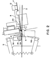
- Fig. 2, 3, 4 and 5 are enlarged partially broken away side elevations of a part of the wire reinforcing device showing various states of a reinforcing operation according to this invention.
- Fig. 6 is an enlarged view of the essential parts of a chuck according to this invention.
- This reinforcing wire 7 has a melting layer which melts under the action of heat.
- the reinforcing device 5 is built around a base 11, this base 11 being parallel to the coil wire 3 which stretches from the tensioner 4 to the winding device 1.
- the device 5 comprises a nozzle 8 which supplies reinforcing wire 7 to the coil wire 3, a guide 6 which guides the coil wire 3 and reinforcing wire 7, a chuck 9 which grasps the coil wire 3 and reinforcing wire 7, a cutter 10 which cuts the reinforcing wire 7, a clamp 12 which functions as a holder for supporting the reinforcing wire 7, and a hot air blower 25 shown in Fig. 2.
- the nozzle 8 and clamp 12 are fixed to a moving platform 14 which moves along the base 11 according to the elongation or contraction of an air cylinder 13.
- the nozzle 8 is a cylindrical member through which the reinforcing wire 7 is threaded, and is supported on the platform 14 at a predetermined inclination angle above the coil wire 3.
- the clamp 12 slides transversely to the reinforcing wire 7 according to the elongation or contraction of an air cylinder 16 provided on the moving platform 14, such that the reinforcing wire 7 is gripped between the clamp 12 and a stopper 17 formed on the moving platform 14.
- the reinforcing wire 7 is supported at a predetermined inclined downward angle above the coil wire 3 by means of the clamp 12 and a roller 19 fixed to the base 11, and is kept under tension by a tensioner 15.
- a path 18 is formed in the moving platform 14 by cutting out a part of it so that the platform 14 and the coil wire 3 do not obstruct each other.
- a reinforcing wire guide 20 is fixed to the base 11 in front of the nozzle 8.
- the guide 20 has a throughhole near its lower end through which the reinforcing wire 7 passes.
- a cutter 10 is supported at the outlet of this throughhole via an air cylinder 22 by a supporter 21 fixed to the base 11. The cutter 10 moves transversely across the outlet of the throughhole according to the elongation and contraction of the air cylinder 22, and thereby cuts the reinforcing wire 7.
- the coil wire 3 passes underneath the cutter 10 and the reinforcing wire guide 20.
- a guide 6 consists of a conduit in a block 6A fixed to the base 11 in front of the cutter 10, and comprises an inlet of large diameter and an outlet of small diameter.
- the coil wire 3 is always threaded through this guide 6.
- the hot air blower 25 faces the outlet of this guide 6.
- the chuck 9 is supported on the base 11 in front of the hole 6 via an air cylinder 23, and slides parallel to the wire 3 according to the elongation and contraction of this air cylinder 23.
- the chuck 9 opens and closes according to the elongation and contraction of an air cylinder 24, and grips the coil wire 3 in a vertical direction.
- Parts 9A and 9B of the chuck 9 which grasp the coil wire 3 and the reinforcing wire 7 both have V-shaped surfaces as shown in Fig. 6, the coil wire 3 and reinforcing wire 7 being supported in a diamond-shaped area formed by the two V-shaped surfaces when the parts 9A and 9B are superposed by sliding them in the directions shown by the arrows in the figure.
- the reinforcing of the coil wire 3 by the reinforcing device 5 is performed according to the following procedure.
- the moving platform 14 is held in its retracted position, and the tip of the reinforcing wire 7 cut by the cutter 10 is situated at the outlet of the throughhole of the reinforcing wire guide 20.
- the clamp 12 has moved down, and the reinforcing wire 7 is gripped between the clamp 12 and stopper 17.
- the platform 14 then moves forward so that the reinforcing wire 7 held by the clamp 12 advances, its tip passes through the reinforcing wire guide 20 to penetrate the inlet of the guide 6, and passes through the guide 6 to project forward from the outlet of same.
- the tip of the reinforcing wire 7 enters the guide 6 smoothly.
- the tip of the reinforcing wire 7 must necessarily touch the coil wire 3 in the neighborhood of the outlet.
- the chuck 9 driven by the air cylinder 23 approaches the guide 6, and grasps the tip of the reinforcing wire 7 projecting from the guide 6 together with the coil wire 3 as shown in Fig. 3.
- the chuck 9 After the chuck 9 has grasped the reinforcing wire 7 and coil wire 3 by moving the V-shaped grips 9A and 9B closer together and superimposing them to form a diamond-shaped area as shown in Fig. 6, the superposition of the grips is increased so as to hold the reinforcing wire 7 and coil wire 3 in close contact.
- the clamp 12 is then raised so as to release the reinforcing wire 7, the chuck 9 is driven forward by the air cylinder 23, and while the coil wire 3 and reinforcing wire 7 are pulled out of the guide 6, hot air is blown from the hot air blower 25.
- the melting layer of the reinforcing wire 7 therefore melts, and the tip of the reinforcing wire 7 fuses to the adjacent coil wire 3.
- the chuck 9 When the tip of the reinforcing wire 7 has fused with the coil wire 3 over a certain length, the chuck 9 is temporarily released, the chuck 9 is moved back toward the guide 6, and the coil wire 3 and reinforcing wire 7 are again grasped in the neighborhood of the outlet of the guide 6 as shown in Fig. 5. The moving platform 14 is then retracted to its original position.
- the bobbin 2 of the winding device 1 is rotated so as to pull the coil wire 3 out of the guide 6.
- the coil wire 3 is therefore pulled out of the guide 6 together with the reinforcing wire 7 whose tip is fused to it.
- Hot air is also blown onto the coil wire 3 and reinforcing wire 7 which have been pulled out of the guide 6, thereby forming a reinforced portion behind and continuous with the reinforced portion already formed.
- the coil wire 3 and reinforcing wire 7 which has been fused with it must pass through the diamond-shaped area formed by the V-shaped grips 9A and 9B while their transverse displacement is restricted.
- the coil wire 3 and reinforcing wire 7 therefore always pass a fixed point between the guide 6 and the chuck 9 while they are in close contact, and fusing of the reinforcing wire 7 to the coil wire 3 is ensured.
- the rotation of the bobbin 2 is recommenced, and while pulling the reinforcing wire 7 and coil wire 3 between the cutter 10 and guide 6 out in front of the guide 6, hot air is blown from the hot air blower 25 so that the end portion of the reinforcing wire 7 is also fused to the coil wire 3. This completes the reinforcing of the coil wire 3.
- the coil wire 3 can thus be reinforced at any desired position and over any desired length.
- the reinforcing necessary at the end of winding the coil wire 3 and the reinforcing necessary at the beginning of winding the wire 3 onto the next bobbin 2 can be performed continuously in one operation. If it necessary to wind the wire 3 onto the terminal pin of the bobbin 2 during the winding procedure, the reinforcing device 5 can be operated on each such occasion.
- the guide 6 may instead take the form of a V-shaped groove, the coil wire 3 and reinforcing wire 7 being brought into close contact by leading them into this groove. In this case, hot air is blown not toward the outlet of the guide 6, but toward the inside of the groove which forms the guide 6.
- An alcohol applicator may also be used instead of the hot air blower as a means of fusing the reinforcing wire 7 to the coil wire 3.
- a fusible layer which liquefies due to the action of alcohol is provided on the reinforcing wire 7
- an alcohol applicator is installed near the guide 6 instead of the hot air blower 25, and alcohol is applied to the reinforcing wire 7 so as to fuse the reinforcing wire 7 to the coil wire 3.
- the hot air blower 25 and the alcohol applicator may of course also be used in conjunction. Further, the fusion may also be performed by means of a laser.
- the reinforcing wire 7 is guided into the fixed guide 6 by moving the clamp 12, however, such arrangement is also possible wherein the clamp 12 is fixed and the guide 6 moves instead.
Landscapes
- Engineering & Computer Science (AREA)
- Power Engineering (AREA)
- Manufacturing & Machinery (AREA)
- Coil Winding Methods And Apparatuses (AREA)
- Wire Processing (AREA)
Description
- This invention relates to the wire reinforcement that has to be carried out when a wire end is tied onto a terminal provided on a rim of a bobbin.
- In coil manufacturing processes, when a wire is wound onto a bobbin, the bobbin is generally rotated by a rotating mechanism, and the bobbin takes up the wire as it is supplied under a certain tension from a tensioning device. The wire is supplied to the bobbin through a long, thin cylindrical nozzle, and by allowing the nozzle to move parallel to the bobbin's rotation axis as the wire is wound, the wire is wound uniformly on the bobbin.
- The ends of the wire are tied onto terminal pins provided on a rim of the coil bobbin respectively at the beginning and end of the winding process. This is achieved by having the nozzle move around the terminal pins of the bobbin, however if the wire is thin, it breaks easily in this process or on the way from the bobbin to the pins. In such a case, the part to be wound onto the terminal pins must first be reinforced, and methods or devices for this purpose are described for example in Japanese Tokkai Hei 2-198983, 3-85707 and 3-227508.
- These methods consist of hanging the wire over a pin and a hook, rotating the hook so as to twist the wire between the pin and the hook, and finally removing the wire from the pin and the hook. The wire is then partially twisted so that the wire has a reinforced portion.
- Wire loops are thus formed at the two reinforced ends, but as part of this reinforced portion is wound on the bobbin as the beginning or end of the wire in the winding process, some of the loops come to be under the other portion of the wire wound on the bobbin.
- If these loops are standing in the outer circumference of the bobbin while the coil is wound on it, therefore, there is a risk that coiled layers of wire having a large difference of electrical potential come into contact with each other and reduce the breakdown voltage of the wire.
- If the wire is twisted by winding it around the pin and the hook a plurality of times, a plurality of loops at the reinforced ends are also formed. If wire is sandwiched between these loops, and the coil is molded by a molding agent after winding, there is also a risk that the wire sandwiched between the loops might break due to the mold pressure.
- Further, if the reinforced part is formed before the wire passes through the aforesaid nozzle, there is a risk that this part will catch on the nozzle when it passes through and break the wire.
- The reinforcing of the wire by twisting it therefore caused various problems.
- It is an object of this invention to reinforce a part of a coil wire without forming a loop.
- It is a further object of this invention to provide an automatic, efficient means of reinforcing wire.
- In order to achieve the above objects, this invention reinforces coil wire between a wire supplying device which supplies the wire and a wire winding device which winds the supplied wire onto a coil bobbin, by guiding the wire over a certain distance in close contact with a reinforcing wire which fuses to the coil wire under predetermined conditions, and applying the fusing conditions to the reinforcing wire within this guide distance.
- Preferably, the reinforcing wire has a fusible layer which melts by the action of heat, and is fused to the coil wire by blowing hot air onto it.
- This invention also provides a device for reinforcing coil wire provided between a wire supply device which supplies the wire and a wire winding device which winds the supplied wire onto a coil bobbin. This device comprises a mechanism for supplying a reinforcing wire which fuses to the coil wire under predetermined conditions, a guide for guiding the coil wire together with the reinforcing wire, a mechanism for threading the tip of the reinforcing wire through the guide, a chuck for gripping and displacing the coil wire together with the reinforcing wire which have passed through the guide, and a mechanism for establishing the predetermined conditions near the guide.
- Preferably, the reinforcing wire has a melting layer which melts due to the action of heat, and the establishing mechanism comprises a hot air blower which blows hot air on the reinforcing wire.
- Also preferably, the guide comprises a conduit having an inlet of large diameter and an outlet of small diameter, and the coil wire and the reinforcing wire pass through this conduit.
- Also preferably, the threading mechanism comprises a releasable holder which holds the reinforcing wire and a mechanism which moves the holder relative to the guide such that the tip of the reinforcing wire penetrates the guide.
- Also preferably, the device is further provided with a cutter which cuts the reinforcing wire between the holder and the guide.
- Also preferably, the chuck comprises a pair of V-shaped grip surfaces which overlap with each other to grip the coil wire and the reinforcing wire.
- The details as well as other features and advantages of this invention are set forth in the remainder of the specification and are shown in the accompanying drawings.
- Fig. 1 is a perspective view of a wire reinforcing device according to this invention.
- Fig. 2, 3, 4 and 5 are enlarged partially broken away side elevations of a part of the wire reinforcing device showing various states of a reinforcing operation according to this invention.
- Fig. 6 is an enlarged view of the essential parts of a chuck according to this invention.
- Referring to Fig. 1 of the drawings, a
coil wire 3 led via tensioner 4 from a wire supply device, not shown, is wound on a rotatingbobbin 2 via a tensioner 4, and a reinforcingdevice 5 installed between the winding device 1 and tensioner 4 attaches a reinforcingwire 7 to thecoil wire 3. This reinforcingwire 7 has a melting layer which melts under the action of heat. - The
reinforcing device 5 is built around a base 11, this base 11 being parallel to thecoil wire 3 which stretches from the tensioner 4 to the winding device 1. Thedevice 5 comprises anozzle 8 which supplies reinforcingwire 7 to thecoil wire 3, aguide 6 which guides thecoil wire 3 and reinforcingwire 7, achuck 9 which grasps thecoil wire 3 and reinforcingwire 7, acutter 10 which cuts the reinforcingwire 7, aclamp 12 which functions as a holder for supporting the reinforcingwire 7, and ahot air blower 25 shown in Fig. 2. - The
nozzle 8 andclamp 12 are fixed to a movingplatform 14 which moves along the base 11 according to the elongation or contraction of anair cylinder 13. Thenozzle 8 is a cylindrical member through which the reinforcingwire 7 is threaded, and is supported on theplatform 14 at a predetermined inclination angle above thecoil wire 3. - The
clamp 12 slides transversely to the reinforcingwire 7 according to the elongation or contraction of anair cylinder 16 provided on the movingplatform 14, such that the reinforcingwire 7 is gripped between theclamp 12 and astopper 17 formed on the movingplatform 14. The reinforcingwire 7 is supported at a predetermined inclined downward angle above thecoil wire 3 by means of theclamp 12 and aroller 19 fixed to the base 11, and is kept under tension by atensioner 15. - A path 18 is formed in the moving
platform 14 by cutting out a part of it so that theplatform 14 and thecoil wire 3 do not obstruct each other. - A reinforcing
wire guide 20 is fixed to the base 11 in front of thenozzle 8. Theguide 20 has a throughhole near its lower end through which the reinforcingwire 7 passes. Acutter 10 is supported at the outlet of this throughhole via anair cylinder 22 by asupporter 21 fixed to the base 11. Thecutter 10 moves transversely across the outlet of the throughhole according to the elongation and contraction of theair cylinder 22, and thereby cuts the reinforcingwire 7. Thecoil wire 3 passes underneath thecutter 10 and the reinforcingwire guide 20. - A
guide 6 consists of a conduit in ablock 6A fixed to the base 11 in front of thecutter 10, and comprises an inlet of large diameter and an outlet of small diameter. Thecoil wire 3 is always threaded through thisguide 6. - The
hot air blower 25 faces the outlet of thisguide 6. - The
chuck 9 is supported on the base 11 in front of thehole 6 via anair cylinder 23, and slides parallel to thewire 3 according to the elongation and contraction of thisair cylinder 23. Thechuck 9 opens and closes according to the elongation and contraction of anair cylinder 24, and grips thecoil wire 3 in a vertical direction. -
Parts chuck 9 which grasp thecoil wire 3 and the reinforcingwire 7 both have V-shaped surfaces as shown in Fig. 6, thecoil wire 3 and reinforcingwire 7 being supported in a diamond-shaped area formed by the two V-shaped surfaces when theparts - The reinforcing of the
coil wire 3 by thereinforcing device 5 is performed according to the following procedure. - In Fig. 2, the moving
platform 14 is held in its retracted position, and the tip of the reinforcingwire 7 cut by thecutter 10 is situated at the outlet of the throughhole of the reinforcingwire guide 20. Theclamp 12 has moved down, and the reinforcingwire 7 is gripped between theclamp 12 and stopper 17. - The
platform 14 then moves forward so that the reinforcingwire 7 held by theclamp 12 advances, its tip passes through the reinforcingwire guide 20 to penetrate the inlet of theguide 6, and passes through theguide 6 to project forward from the outlet of same. - As the inlet of the
guide 6 has a large diameter, the tip of the reinforcingwire 7 enters theguide 6 smoothly. On the other hand, as the outlet has a small diameter, the tip of the reinforcingwire 7 must necessarily touch thecoil wire 3 in the neighborhood of the outlet. - The
chuck 9 driven by theair cylinder 23 approaches theguide 6, and grasps the tip of the reinforcingwire 7 projecting from theguide 6 together with thecoil wire 3 as shown in Fig. 3. - After the
chuck 9 has grasped the reinforcingwire 7 andcoil wire 3 by moving the V-shaped grips wire 7 andcoil wire 3 in close contact. - The
clamp 12 is then raised so as to release the reinforcingwire 7, thechuck 9 is driven forward by theair cylinder 23, and while thecoil wire 3 and reinforcingwire 7 are pulled out of theguide 6, hot air is blown from thehot air blower 25. The melting layer of the reinforcingwire 7 therefore melts, and the tip of the reinforcingwire 7 fuses to theadjacent coil wire 3. - When the tip of the reinforcing
wire 7 has fused with thecoil wire 3 over a certain length, thechuck 9 is temporarily released, thechuck 9 is moved back toward theguide 6, and thecoil wire 3 and reinforcingwire 7 are again grasped in the neighborhood of the outlet of theguide 6 as shown in Fig. 5. The movingplatform 14 is then retracted to its original position. - Next, the
bobbin 2 of the winding device 1 is rotated so as to pull thecoil wire 3 out of theguide 6. Thecoil wire 3 is therefore pulled out of theguide 6 together with the reinforcingwire 7 whose tip is fused to it. Hot air is also blown onto thecoil wire 3 and reinforcingwire 7 which have been pulled out of theguide 6, thereby forming a reinforced portion behind and continuous with the reinforced portion already formed. As thechuck 9 is closed, thecoil wire 3 and reinforcingwire 7 which has been fused with it must pass through the diamond-shaped area formed by the V-shapedgrips coil wire 3 and reinforcingwire 7 therefore always pass a fixed point between theguide 6 and thechuck 9 while they are in close contact, and fusing of the reinforcingwire 7 to thecoil wire 3 is ensured. - After the reinforcing
wire 7 andcoil wire 3 have been fused over a predetermined length, the rotation of the bobbin 1 is stopped, the reinforcingwire 7 is held by theclamp 12, and then cut at the outlet of the throughhole in the reinforcingwire guide 20 by means of thecutter 10. - After cutting, the rotation of the
bobbin 2 is recommenced, and while pulling the reinforcingwire 7 andcoil wire 3 between thecutter 10 andguide 6 out in front of theguide 6, hot air is blown from thehot air blower 25 so that the end portion of the reinforcingwire 7 is also fused to thecoil wire 3. This completes the reinforcing of thecoil wire 3. Thecoil wire 3 can thus be reinforced at any desired position and over any desired length. - By means of the aforesaid procedure, the reinforcing necessary at the end of winding the
coil wire 3 and the reinforcing necessary at the beginning of winding thewire 3 onto thenext bobbin 2, can be performed continuously in one operation. If it necessary to wind thewire 3 onto the terminal pin of thebobbin 2 during the winding procedure, the reinforcingdevice 5 can be operated on each such occasion. - As there is no loop in the
coil wire 3 or the reinforcingwire 7 when forming the reinforced portion, therefore, there is no risk that thecoil wire 3 will have a reduced breakdown voltage or that thecoil wire 3 will be damaged when molding is carried out after winding, even if part of the reinforced portion is wound onto thebobbin 2 during winding. Besides there is no risk that a loop will catch on the nozzle of the winding device 1. - In the aforesaid embodiment, the
guide 6 may instead take the form of a V-shaped groove, thecoil wire 3 and reinforcingwire 7 being brought into close contact by leading them into this groove. In this case, hot air is blown not toward the outlet of theguide 6, but toward the inside of the groove which forms theguide 6. - An alcohol applicator may also be used instead of the hot air blower as a means of fusing the reinforcing
wire 7 to thecoil wire 3. In this case, a fusible layer which liquefies due to the action of alcohol is provided on the reinforcingwire 7, an alcohol applicator is installed near theguide 6 instead of thehot air blower 25, and alcohol is applied to the reinforcingwire 7 so as to fuse the reinforcingwire 7 to thecoil wire 3. Thehot air blower 25 and the alcohol applicator may of course also be used in conjunction. Further, the fusion may also be performed by means of a laser. - In the aforesaid embodiment, the reinforcing
wire 7 is guided into the fixedguide 6 by moving theclamp 12, however, such arrangement is also possible wherein theclamp 12 is fixed and theguide 6 moves instead.
Claims (8)
- A method for reinforcing coil wire (3) between a wire supplying device which supplies said wire (3) and a wire winding device (1) which winds said supplied wire (3) onto a coil bobbin (2), characterized in that:said wire (3) is guided over a certain distance in close contact with a reinforcing wire (7) which fuses to said coil wire (3) under predetermined conditions, andthe fusing conditions are applied to said reinforcing wire (7) within said guide distance.
- A reinforcing method as defined in claim 1 wherein said reinforcing wire (7) has a fusible layer which melts by the action of heat, and is fused to said coil wire (3) by blowing hot air onto it.
- A device for reinforcing coil wire (3) provided between a wire supply device which supplies said wire (3) and a wire winding device (1) which winds said supplied wire (3) onto a coil bobbin(2), comprising:means for supplying a reinforcing wire (7) which fuses to said coil wire (3) under predetermined conditions,a guide (6) for guiding said coil wire (3) together with said reinforcing wire (7)means for threading the tip of said reinforcing wire (7) through said guide (6),a chuck (9) for gripping and displacing said coil wire (3) together with said reinforcing wire (7) which have passed through said guide (6), andmeans for establishing said predetermined conditions near said guide (6).
- A device for reinforcing coil wire (3) as defined in claim 3 wherein said reinforcing wire (7) has a melting layer which melts due to the action of heat, and said establishing means comprises a hot air blower (25) which blows hot air on said reinforcing wire (7).
- A device for reinforcing coil wire (3) as defined in claim 3 wherein said guide (6) is a conduit through which said coil wire (3) and said reinforcing wire (7) pass, said conduit having an inlet of large diameter and an outlet of small diameter.
- A device for reinforcing coil wire (3) as defined in claim 3 wherein said threading means comprises a releasable holder (12) which holds said reinforcing wire (7) and a mechanism (13, 14) which moves said holder (12) relative to said guide (6) such that the tip of said reinforcing wire (7) penetrates said guide (6).
- A device for reinforcing coil wire (3) as defined in claim 6 further comprising a cutter (10) which cuts said reinforcing wire (7) between said holder (12) and said guide (6).
- A device for reinforcing coil wire (3) as defined in claim 3 wherein said chuck (9) comprises a pair of V-shaped grip surfaces (9A, 9B) which overlap with each other to grip said coil wire (3) and said reinforcing wire (7).
Applications Claiming Priority (4)
| Application Number | Priority Date | Filing Date | Title |
|---|---|---|---|
| JP4066963A JPH05275260A (en) | 1992-03-25 | 1992-03-25 | Reinforcement of coil line material |
| JP66963/92 | 1992-03-25 | ||
| JP4222874A JPH0669060A (en) | 1992-08-21 | 1992-08-21 | Reinforcement apparatus of wire for coil |
| JP222874/92 | 1992-08-21 |
Publications (2)
| Publication Number | Publication Date |
|---|---|
| EP0562602A1 EP0562602A1 (en) | 1993-09-29 |
| EP0562602B1 true EP0562602B1 (en) | 1996-09-11 |
Family
ID=26408164
Family Applications (1)
| Application Number | Title | Priority Date | Filing Date |
|---|---|---|---|
| EP93104950A Expired - Lifetime EP0562602B1 (en) | 1992-03-25 | 1993-03-25 | Method and device for reinforcing coil wires |
Country Status (2)
| Country | Link |
|---|---|
| EP (1) | EP0562602B1 (en) |
| DE (1) | DE69304577T2 (en) |
Families Citing this family (2)
| Publication number | Priority date | Publication date | Assignee | Title |
|---|---|---|---|---|
| GB2372346A (en) * | 2001-02-19 | 2002-08-21 | Moy Park Ltd | Tracing components of a production chain |
| CN109994313B (en) * | 2019-04-10 | 2020-11-24 | 东莞市纵易智能装备有限公司 | New energy automobile power transformer conjoined coil sandwich winding method automatic winding machine |
Family Cites Families (1)
| Publication number | Priority date | Publication date | Assignee | Title |
|---|---|---|---|---|
| IT1074884B (en) * | 1977-06-09 | 1985-04-20 | Camardella Giuseppe | BRAID DEVICE SUITABLE FOR INTERMITTENTLY FORMING A BRAID OF WIRE, STARTING FROM A SINGLE LINE POWERED WITHOUT INTERRUPTION |
-
1993
- 1993-03-25 DE DE69304577T patent/DE69304577T2/en not_active Expired - Fee Related
- 1993-03-25 EP EP93104950A patent/EP0562602B1/en not_active Expired - Lifetime
Also Published As
| Publication number | Publication date |
|---|---|
| EP0562602A1 (en) | 1993-09-29 |
| DE69304577D1 (en) | 1996-10-17 |
| DE69304577T2 (en) | 1997-01-23 |
Similar Documents
| Publication | Publication Date | Title |
|---|---|---|
| JP3688322B2 (en) | Suture cutting system and cutting method | |
| EP3521490A1 (en) | Yarn guide for a spinning unit of a ring spinning machine, a ring spinning machine and a method for threading yarn into the yarn guide | |
| CN110603218A (en) | Apparatus and method for winding and cutting wire or cable | |
| JPS6115021B2 (en) | ||
| JPS60155742A (en) | Method and apparatus for spinning yarn in fine spinning apparatus of oe-friction fine spinning frame | |
| US4708298A (en) | Winding apparatus | |
| EP0581493A1 (en) | Wire refeeding device and method for wire-cut electroerosion apparatus | |
| EP0562602A1 (en) | Method and device for reinforcing coil wires | |
| KR100776952B1 (en) | How to wind the texturing device and running thread | |
| US4494368A (en) | Method of preventing irregular untwisting of yarn ends in splicing spun yarns | |
| EP0872852A2 (en) | Universal cable take-off system | |
| US5692690A (en) | Cable snagger for winding a continuously produced cable onto a take-up spool | |
| JP2005219853A (en) | Wire rod drawing method, wire drawing device, and optical fiber manufacturing method | |
| US4980531A (en) | Prehesive device for the electrode wire of an EDM cutting machine | |
| JPH03206152A (en) | Weft supply device for use in fluid jet loom | |
| CN1330807C (en) | Apparatus for making a tow comprising a plurality of glass filaments | |
| AU688883B2 (en) | Improvements in or relating to electrofusion couplers | |
| JPS63170238A (en) | Optical fiber winding device | |
| JP2748332B2 (en) | Automatic lining control method for proof tester | |
| JPH0669060A (en) | Reinforcement apparatus of wire for coil | |
| US6534122B1 (en) | Method and arrangement in connection with optical fiber coating | |
| JP4148541B2 (en) | Synthetic yarn bundling method and bundling apparatus | |
| CA1037695A (en) | Method for restringing a threadline | |
| JP3488305B2 (en) | Wire wrapping equipment | |
| JPH05275260A (en) | Reinforcement of coil line material |
Legal Events
| Date | Code | Title | Description |
|---|---|---|---|
| PUAI | Public reference made under article 153(3) epc to a published international application that has entered the european phase |
Free format text: ORIGINAL CODE: 0009012 |
|
| AK | Designated contracting states |
Kind code of ref document: A1 Designated state(s): CH DE FR GB IT LI |
|
| RIN1 | Information on inventor provided before grant (corrected) |
Inventor name: KOMURO, KATSUROU C/O URAWA FACTORY |
|
| 17P | Request for examination filed |
Effective date: 19940328 |
|
| 17Q | First examination report despatched |
Effective date: 19951004 |
|
| GRAH | Despatch of communication of intention to grant a patent |
Free format text: ORIGINAL CODE: EPIDOS IGRA |
|
| GRAH | Despatch of communication of intention to grant a patent |
Free format text: ORIGINAL CODE: EPIDOS IGRA |
|
| GRAA | (expected) grant |
Free format text: ORIGINAL CODE: 0009210 |
|
| AK | Designated contracting states |
Kind code of ref document: B1 Designated state(s): CH DE FR GB IT LI |
|
| PG25 | Lapsed in a contracting state [announced via postgrant information from national office to epo] |
Ref country code: LI Effective date: 19960911 Ref country code: FR Effective date: 19960911 Ref country code: CH Effective date: 19960911 |
|
| REF | Corresponds to: |
Ref document number: 69304577 Country of ref document: DE Date of ref document: 19961017 |
|
| ITF | It: translation for a ep patent filed | ||
| EN | Fr: translation not filed | ||
| REG | Reference to a national code |
Ref country code: CH Ref legal event code: PL |
|
| PLBE | No opposition filed within time limit |
Free format text: ORIGINAL CODE: 0009261 |
|
| 26N | No opposition filed | ||
| PGFP | Annual fee paid to national office [announced via postgrant information from national office to epo] |
Ref country code: GB Payment date: 19990222 Year of fee payment: 7 |
|
| PGFP | Annual fee paid to national office [announced via postgrant information from national office to epo] |
Ref country code: DE Payment date: 19990428 Year of fee payment: 7 |
|
| PG25 | Lapsed in a contracting state [announced via postgrant information from national office to epo] |
Ref country code: GB Free format text: LAPSE BECAUSE OF NON-PAYMENT OF DUE FEES Effective date: 20000325 |
|
| GBPC | Gb: european patent ceased through non-payment of renewal fee |
Effective date: 20000325 |
|
| PG25 | Lapsed in a contracting state [announced via postgrant information from national office to epo] |
Ref country code: DE Free format text: LAPSE BECAUSE OF NON-PAYMENT OF DUE FEES Effective date: 20010103 |
|
| PG25 | Lapsed in a contracting state [announced via postgrant information from national office to epo] |
Ref country code: IT Free format text: LAPSE BECAUSE OF NON-PAYMENT OF DUE FEES;WARNING: LAPSES OF ITALIAN PATENTS WITH EFFECTIVE DATE BEFORE 2007 MAY HAVE OCCURRED AT ANY TIME BEFORE 2007. THE CORRECT EFFECTIVE DATE MAY BE DIFFERENT FROM THE ONE RECORDED. Effective date: 20050325 |