EP0562545B2 - Temperature control device for rooms in a building which border on a facade - Google Patents
Temperature control device for rooms in a building which border on a facade Download PDFInfo
- Publication number
- EP0562545B2 EP0562545B2 EP93104747A EP93104747A EP0562545B2 EP 0562545 B2 EP0562545 B2 EP 0562545B2 EP 93104747 A EP93104747 A EP 93104747A EP 93104747 A EP93104747 A EP 93104747A EP 0562545 B2 EP0562545 B2 EP 0562545B2
- Authority
- EP
- European Patent Office
- Prior art keywords
- facade
- temperature control
- control device
- profile
- pipe
- Prior art date
- Legal status (The legal status is an assumption and is not a legal conclusion. Google has not performed a legal analysis and makes no representation as to the accuracy of the status listed.)
- Expired - Lifetime
Links
Images


Classifications
-
- F—MECHANICAL ENGINEERING; LIGHTING; HEATING; WEAPONS; BLASTING
- F24—HEATING; RANGES; VENTILATING
- F24D—DOMESTIC- OR SPACE-HEATING SYSTEMS, e.g. CENTRAL HEATING SYSTEMS; DOMESTIC HOT-WATER SUPPLY SYSTEMS; ELEMENTS OR COMPONENTS THEREFOR
- F24D3/00—Hot-water central heating systems
- F24D3/12—Tube and panel arrangements for ceiling, wall, or underfloor heating
- F24D3/14—Tube and panel arrangements for ceiling, wall, or underfloor heating incorporated in a ceiling, wall or floor
- F24D3/147—Tube and panel arrangements for ceiling, wall, or underfloor heating incorporated in a ceiling, wall or floor arranged in facades
-
- Y—GENERAL TAGGING OF NEW TECHNOLOGICAL DEVELOPMENTS; GENERAL TAGGING OF CROSS-SECTIONAL TECHNOLOGIES SPANNING OVER SEVERAL SECTIONS OF THE IPC; TECHNICAL SUBJECTS COVERED BY FORMER USPC CROSS-REFERENCE ART COLLECTIONS [XRACs] AND DIGESTS
- Y02—TECHNOLOGIES OR APPLICATIONS FOR MITIGATION OR ADAPTATION AGAINST CLIMATE CHANGE
- Y02B—CLIMATE CHANGE MITIGATION TECHNOLOGIES RELATED TO BUILDINGS, e.g. HOUSING, HOUSE APPLIANCES OR RELATED END-USER APPLICATIONS
- Y02B30/00—Energy efficient heating, ventilation or air conditioning [HVAC]
Definitions
- the invention relates to a facade for external limitation of rooms in a building from one formed by mullion and transom profiles Framework and from filling the frame fields Frame elements with a device for Tempering the rooms mentioned.
- a facade of this type is known (EP-A-0 193 810), one through the hollow interior of the supports and bars extending, the heating medium leading Pipeline is provided.
- the pipeline With the pipeline is a heat transfer profile via a thermal contact element connected.
- the heat transfer profile takes up the pipeline in a half-shell, which over Thermal conductors with the inner wall of the heat transfer profile connected is.
- the heat transfer profile with the half-shell receiving the pipeline extends over the entire length of the support or. of the transom profile and thus forms a component of these facades profiles created by the facade builder the construction site incorporated into the facade construction must become.
- the facade builder the heating engineer will be active, who the the heating medium leading pipeline into the half shells mentioned insert and fasten and the transitions between must create the support and transom profiles.
- the invention has for its object a facade of the type mentioned in such a way that the metalwork when creating the facade independently from the laying work of the heating medium leading pipeline can be made the heating pipes can be retrofitted, notches the facade is eliminated and the use of in heating construction known elements is possible.
- the solution according to the invention ensures that the heating engineer does no metalwork must and that the metal worker does not deal with the Problems in heating construction.
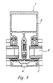
- the post or bar shown in Fig. 1 consists of a facade profile 2 and a cover profile 3, using 4 screws on the facade profile is attached. From the facade profile and the cover profile the edges are taken up by insulating glass panes 5, the ones formed by the posts and transoms Fill in the frame fields.
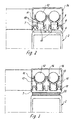
- the facade profile 2 according to FIG. 1 can accordingly the embodiments of FIGS. 2 and 3 with a device for tempering a to the Facade bordering building room equipped or be upgraded.
- an attachment profile 7 which means Screws or locking devices with the facade profile 2 can be connected.
- This attachment profile 7 has groove webs 8 and 9, limit the anchoring grooves 10, in which in the illustrated embodiments, the mounting feet are fixed by holders 11. Through the holder 11 the pipes 12 leading a heating medium to the Attachment profile 7 and thus fixed to facade profile 2. The Holders are distributed over the pipe length. You can use the anchor groove anywhere be determined.
- the holders in those shown in the drawings Exemplary embodiments have clamping legs 13, 14 on, which are adapted to the outer contour of the tube 12 and form a receptacle for the pipe.
- the clamp legs extend over an angular range that is greater than 180 °.
- a support bar 15 is provided for the tube 12 and end pieces 16 are attached to the leg ends, the triangular in the embodiment Cross-section are formed and from the clamping legs project inwards so that between the Clamp leg and the tube 12 in the area between the support bar 15 and the end piece 16 a gap 17 is provided.
- the holders are preferably made of plastic and have a mounting foot that the Embodiments of FIGS. 2,3,6,7 and 8 two spaced apart, parallel to each other extending clamping webs 18.
- the clamping bars 18 have an arrow-shaped end piece at the free end 19 on.
- This arrow-shaped end piece 19 engages behind the Groove webs 8.9 a locking edge, so that due to the Shape and material suspension of the mounting foot Clamping bars with their arrow-shaped end piece Fit non-positively on the groove webs 8.9.
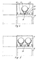
- 4 and 5 are holder 21 for receiving and Determination of the tubes 12 shown, in which the training of the mounting base deviating from the holders 11 is.
- the mounting foot of the holder 21 has a support bar 22 on the free longitudinal edges the groove webs 23 are supported. Extends from this support bar engaging in the anchoring groove Clamp bar 24.
- the facade profile 25 is equipped with groove webs 23, formed by the three anchoring grooves 26 will.
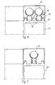
- a facade profile 27 is shown, which is equipped with a groove pattern that the corresponds to the attachment profile 7 according to FIGS. 2 and 3.
- the groove webs 8 and 9 form two parallel to each other extending anchoring grooves 10, in which accordingly 6 two heating tubes 12 or corresponding 7 a heating tube 12 can be fixed.
- a heat exchange profile 28 is clipped onto ds.
- This The heat exchange profile is radiating outwards extending ribs 29, which are a surface enlargement result and thus the heat radiation improve.
- the shown in Fig. 8 and on the heating tube 12 clipped-on heat exchange profile 28 encompasses this Heating tube 12 over an angular range that is little larger than 180 °.
- the length of the heat exchange profile 28 corresponds the distance between two adjacent holders 11.
- the heating system should preferably be inert Low temperature system can be used, which in particular has the advantage that strong temperature fluctuations do not act on the facade construction.
- the heat transfer from the heating medium to the ambient air takes place in particular via heat radiation, which intensifies according to the embodiment according to FIG. 8 can be.
- Fig. 9 shows a facade profile 29, the one in the middle area provided web 30 on both Sides anchoring grooves 31, which by groove webs 32 can be limited.
- holder 21 pipes 12 carrying a heating medium on the facade profile fixed.
- the heating pipes are opposed by a cover profile 33 encapsulates the room to be tempered.
- caps 34, 35 are provided, through which a heating medium leading pipes compared to the one to be heated Space to be covered. These caps will be made of a good heat-conducting material.
Abstract
Description
Die Erfindung bezieht sich auf eine Fassade zur Außenbegrenzung von Räumen eines Gebäudes, bestehend aus einem von Pfosten- und Riegelprofilen gebildeten Rahmenwerk und aus die Rahmenfelder ausfüllenden Rahmenelementen mit einer Vorrichtung zum Temperieren der genannten Räume.The invention relates to a facade for external limitation of rooms in a building from one formed by mullion and transom profiles Framework and from filling the frame fields Frame elements with a device for Tempering the rooms mentioned.
Es ist eine Fassade dieser Art bekannt (EP-A-0 193 810), bei der eine durch den hohlen Innenraum der Stützen und Riegel sich erstreckende, das Heizmedium führende Rohrleitung vorgesehen ist. Mit der Rohrleitung ist ein Wärmeübertragungsprofil über ein Wärmeleitkontaktelement verbunden. Das Wärmeübertragungsprofil nimmt in einer Halbschale die Rohrleitung auf, die über Wärmeleitstege mit der Innenwand des Wärmeübertragungsprofils verbunden ist. Das Wärmeübertragungsprofil mit der die Rohrleitung aufnehmenden Halbschale erstreckt sich über die gesamte Länge des Stütz-bzw. des Riegelprofils und bildet somit ein Bauteil dieser Fassaden profile, das vom Fassadenbauer erstellt und an der Baustelle in die Fassadenkonstruktion eingearbeitet werden muß. Gleichzeitig mit dem Fassadenbauer muß der Heizungsbauer tätig werden, der die das Heizmedium führende Rohrleitung in die genannten Halbschalen einlegen und befestigen sowie die Übergänge zwischen den Stütz- und Riegelprofilen erstellen muß. Diese Arbeiten sind mit den entsprechenden Werkzeugen durchzuführen.A facade of this type is known (EP-A-0 193 810), one through the hollow interior of the supports and bars extending, the heating medium leading Pipeline is provided. With the pipeline is a heat transfer profile via a thermal contact element connected. The heat transfer profile takes up the pipeline in a half-shell, which over Thermal conductors with the inner wall of the heat transfer profile connected is. The heat transfer profile with the half-shell receiving the pipeline extends over the entire length of the support or. of the transom profile and thus forms a component of these facades profiles created by the facade builder the construction site incorporated into the facade construction must become. At the same time with the facade builder the heating engineer will be active, who the the heating medium leading pipeline into the half shells mentioned insert and fasten and the transitions between must create the support and transom profiles. These works are to be carried out with the appropriate tools.
Der Erfindung liegt die Aufgabe zugrunde, eine Fassade der eingangs genannten Art so zu gestalten, daß die Metallarbeiten bei der Erstellung der Fassade unabhängig von den Verlegungsarbeiten der das Heizmedium führenden Rohrleitung vorgenommen werden können, die Heizrohre nachrüstbar sind, Ausklinkungen an der Fassade entfallen und die Verwendung von im Heizungsbau bekannten Elementen möglich ist.The invention has for its object a facade of the type mentioned in such a way that the metalwork when creating the facade independently from the laying work of the heating medium leading pipeline can be made the heating pipes can be retrofitted, notches the facade is eliminated and the use of in heating construction known elements is possible.
Diese Aufgabe wird durch die Merkmale des Patentanspruches 1 gelöst.This object is achieved by the features of the claim 1 solved.
Das Festlegen der Rohre in den Haltern und das Befestigen der Halter an den Fassadenprofilen oder an den Zusatzprofilen und die Festlegung der Abdeckkappen an den Fassadenprofilen oder an den Zusatzprofilen erfolgt erfindungsgemäß durch Rastverbindungen, also ohne Einsatz von Werkzeugen.Fixing the pipes in the holders and fastening the holder on the facade profiles or on the Additional profiles and the determination of the cover caps the facade profiles or on the additional profiles according to the invention by locking connections, that is, without Use of tools.
Durch die Halter sind die ein Heizmedium führenden Rohre an dem jeweiligen sich aus der Konstruktion ergebenden Punkt an der Fassade festgelegt, so daß Winkel- und T-Abgänge im Boden-, Riegel- und Deckenbereich mit den herkömmlichen Mitteln des Heizungsbaus ausgeführt werden können. Gerade T- und Eckanschlüsse weisen z.T. größere Durchmesser als die Rohre selbst auf, so daß bei den nach dem Stand der Technik bekannten Lösungen aufwendige Klink- und Ausnehmungsarbeiten an den entsprechenden Fassadenprofilen vorgenommen werden müssen.Through the holder are the one leading a heating medium Pipes on the respective resulting from the construction Point on the facade so that angular and T-exits in the floor, transom and ceiling area with the conventional means of heating construction can be executed. Straight T and corner connections partially larger diameter than the pipes itself on, so that in the state of the art known solutions elaborate pawl and recess work on the corresponding facade profiles must be made.
Bei der erfindungsgemäßen Lösung ist sichergestellt, daß der Heizungsbauer keine Metallarbeiten ausführen muß und daß der Metallbauer sich nicht mit den Problemen des Heizungsbaus zu befassen hat.The solution according to the invention ensures that the heating engineer does no metalwork must and that the metal worker does not deal with the Problems in heating construction.
Ausgestaltungen der Erfindung ergeben sich aus den Unteransprüchen.Refinements of the invention result from the subclaims.
Ausführungsbeispiele der Erfindung sind in den Zeichnungen dargestellt und werden im folgenden beschrieben. Es zeigen:
- Fig. 1
- einen Pfosten bzw. einen Riegel einer Fassade im Schnitt,
- Fig. 2 und 3
- das Fassadenprofil nach der Fig. 1, das mit einem Aufsatzprofil nachgerüstet ist, an dem ein Heizmedium führende Rohre befestigt sind,
- Fig. 4 und 5
- ein Fassadenprofil, das mit Verankerungsnuten für Heizrohre ausgestattet ist,
- Fig. 6 und 7
- ein Fassadenprofil, das an der dem zu temperierenden Innenraum zugewandten Seite mit einem von den Fig. 4 und 5 abweichenden Bild von Verankerungsnuten für die Heizrohre ausgestattet ist, und
- Fig. 8
- ein an einem Fassadenprofil festgelegtes Heizrohr, das mit einem Wärmetauschprofil ausgerüstet ist, und
- Fig. 9
- ein weiteres mit ein Heizmedium führenden Rohren versehenes Fassadenprofil.
- Fig. 1
- a post or a transom of a facade in section,
- 2 and 3
- 1, which is retrofitted with an attachment profile on which pipes carrying a heating medium are attached,
- 4 and 5
- a facade profile that is equipped with anchoring grooves for heating pipes,
- 6 and 7
- a facade profile, which is equipped on the side facing the temperature-controlled interior with a deviating from FIGS. 4 and 5 of anchoring grooves for the heating pipes, and
- Fig. 8
- a heating pipe fixed to a facade profile and equipped with a heat exchange profile, and
- Fig. 9
- another facade profile provided with pipes carrying a heating medium.
Der in der Fig. 1 aufgezeigte Pfosten oder Riegel
besteht aus einem Fassadenprofil 2 und einem Abdeckprofil
3, das mittels Schrauben 4 an dem Fassadenprofil
befestigt ist. Von dem Fassadenprofil und dem Abdeckprofil
werden die Ränder von Isolierglasscheiben 5 aufgenommen,
die die von den Pfosten und Riegeln gebildeten
Rahmenfelder ausfüllen.The post or bar shown in Fig. 1
consists of a
Das Fassadenprofil 2 nach der Fig. 1 kann entsprechend
den Ausführungsbeispielen nach den Fig. 2 und
3 mit einer Vorrichtung zum Temperieren eines an die
Fassade grenzenden Gebäuderaumes ausgerüstet
oder nachgerüstet werden.The
Bei den Ausführungsbeispielen nach den Fig. 2 und
3 ist an der dem Innenraum zugewandten Seite 6 des
Fassadenprofils 2 ein Aufsatzprofil 7 befestigt, das mittels
Schrauben oder Rastmittel mit dem Fassadenprofil
2 verbunden werden kann.In the embodiments according to FIGS. 2 and
3 is on the side facing the
Dieses Aufsatzprofil 7 weist Nutstege 8 und 9 auf,
die Verankerungsnuten 10 begrenzen, in denen in den
dargestellten Ausführungsbeispielen die Befestigungsfüße
von Haltern 11 festgelegt sind. Durch die Halter 11
werden die ein Heizmedium führenden Rohre 12 an dem
Aufsatzprofil 7 und damit am Fassadenprofil 2 fixiert. Die
Halter werden über die Rohrlänge verteilt angeordnet.
Sie können an einer beliebigen Stelle der Verankerungsnut
festgelegt werden.This
Die Halter in den in den Zeichnungen dargestellten
Ausführungsbeispielen weisen Klemmschenkel 13,14
auf, die der Außenkontur des Rohres 12 angepaßt sind
und eine Aufnahme für das Rohr bilden. Die Klemmschenkel
erstrecken sich über einen Winkelbereich, der
größer als 180° ist. Im Sohlenbereich der Klemmschenkel
ist eine Stützleiste 15 für das Rohr 12 vorgesehen
und an den Schenkelenden sind Endstücke 16 angebracht,
die im Ausführungsbeispiel dreieckförmig im
Querschnitt ausgebildet sind und von den Klemmschenkeln
nach innen vorspringen, so daß zwischen dem
Klemmschenkel und dem Rohr 12 im Bereich zwischen
der Stützleiste 15 und dem Endstück 16 ein Spaltraum
17 vorgesehen ist.The holders in those shown in the drawings
Exemplary embodiments have
Die Halter werden vorzugsweise aus Kunststoff gefertigt
und besitzen einen Befestigungsfuß, der bei den
Ausführungsbeispielen nach den Fig. 2,3,6,7 und 8 aus
zwei in Abstand voneinander angeordneten, parallel sich
erstrekkenden Klemmstegen 18 besteht. Die Klemmstege
18 weisen am freien Ende ein pfeilförmiges Endstück
19 auf.The holders are preferably made of plastic
and have a mounting foot that the
Embodiments of FIGS. 2,3,6,7 and 8
two spaced apart, parallel to each other
extending
Dieses pfeilförmige Endstück 19 hintergreift an den
Nutstegen 8,9 eine Rastkante, so daß aufgrund der
Form- und Materialfederung des Befestigungsfußes die
Klemmstege mit ihrem pfeilförmigen Endstück form- und
kraftschlüssig an den Nutstegen 8,9 anliegen.This arrow-
Während bei der Ausführungsform nach der Fig. 2
das Aufsatzprofil 7 unmittelbar sich an den Fassadenprofil
2 abstützt, ist bei der Konstruktion nach der Fig. 3
zwischen dem Aufsatzprofil 7 und dem Fassadenprofil
eine Wärmedämmschicht 20 vorgesehen.While in the embodiment according to FIG. 2
the
In den Fig. 4 und 5 sind Halter 21 zur Aufnahme und
Festlegung der Rohre 12 dargestellt, bei denen die Ausbildung
des Befestigungsfußes von den Haltern 11 abweichend
ist.4 and 5 are holder 21 for receiving and
Determination of the
Der Befestigungsfuß des Halters 21 weist eine Auflageleiste
22 auf, die sich an den freien Längsrändern
der Nutstege 23 abstützt. Von dieser Auflageleiste erstreckt
sich ein in die Verankerungsnut eingreifender
Klemmsteg 24.The mounting foot of the
Während bei den Ausführungsbeispielen nach den
Fig. 2 und 3 die Nutstege 8 und 9 Teile eines Aufsatzprofils
7 sind, sind bei den übrigen dargestellten Ausführungsformen
die die Verankerungsnuten begrenzenden
Nutstege mit dem Fassadenprofil einstückig.While in the embodiments according to the
2 and 3, the
Das Fassadenprofil 25 ist mit Nutstegen 23 ausgerüstet,
durch die drei Verankerungsnuten 26 gebildet
werden.The
Bei diesem Nutbild, das in den Fig. 4 und 5 aufgezeigt
ist, besteht die Möglichkeit, entweder ein Heizrohr
12 in der mittleren Verankerungsnut oder zwei parallel
zueinander verlaufende Heizrohre in den äußeren Verankerungsnuten
festzulegen.In this groove pattern, which is shown in FIGS. 4 and 5
there is the possibility of either a
In den Fig. 6 und 7 ist ein Fassadenprofil 27 aufgezeigt,
das mit einem Nutbild ausgestattet ist, das dem
des Aufsatzprofils 7 nach den Fig. 2 und 3 entspricht.6 and 7, a
Die Nutstege 8 und 9 bilden zwei parallel zueinander
verlaufende Verankerungsnuten 10, in denen entsprechend
der Fig. 6 zwei Heizrohre 12 oder entsprechend
der Fig. 7 ein Heizrohr 12 festgelegt werden kann.The
Bei dem Ausführungsbeispiel nach der Fig. 8 ist das
Fassadenprofil 27 mit einem Heizrohr 12 ausgerüstet,
auf ds ein Wärmetauschprofil 28 aufgeklipst ist. Dieses
Wärmetauschprofil weist strahlenförmig sich nach außen
erstreckende Rippen 29 auf, die eine Oberflächenvergrößerung
ergeben und damit die Wärmeabstrahlung
verbessern.In the embodiment according to FIG. 8 that is
Das in der Fig. 8 aufgezeigte und auf das Heizrohr
12 aufgeklipste Wärmetauschprofil 28 umgreift das
Heizrohr 12 über einen Winkelbereich, der wenig größer
als 180° ist. Die Länge des Wärmetauschprofils 28 entspricht
dem Abstand zweier benachbarter Halter 11.The shown in Fig. 8 and on the
Vorzugsweise soll das Heizungssystem als träges Niedertemperatursystem genutzt werden, was insbesondere den Vorteil hat, daß starke Temperaturschwankungen auf die Fassadenkonstruktion nicht einwirken. Die Wärmeübertragung vom Heizmedium auf die Umgebungsluft erfolgt insbesondere über Wärmestrahlung, die gemäß der Ausführung nach der Fig. 8 intensiviert werden kann.The heating system should preferably be inert Low temperature system can be used, which in particular has the advantage that strong temperature fluctuations do not act on the facade construction. The heat transfer from the heating medium to the ambient air takes place in particular via heat radiation, which intensifies according to the embodiment according to FIG. 8 can be.
Die Fig. 9 zeigt ein Fassadenprofil 29, das an einem
im mittleren Bereich vorgesehenen Steg 30 an beiden
Seiten Verankerungsnuten 31 aufweist, die durch Nutstege
32 begrenzt werden. Durch Halter 21 werden die
ein Heizmedium führenden Rohre 12 an dem Fassadenprofil
festgelegt.Fig. 9 shows a
Die Heizrohre werden durch ein Abdeckprofil 33 gegenüber
dem zu temperierenden Raum verkapselt.The heating pipes are opposed by a
Auch bei den übrigen erörterten Ausführungsformen sind Kappen 34,35 vorgesehen, durch die die ein Heizmedium führenden Rohre gegenüber dem aufzuheizenden Raum abgedeckt werden. Diese Kappen werden aus einem gut wärmeleitenden Material gefertigt.Also in the other discussed embodiments caps 34, 35 are provided, through which a heating medium leading pipes compared to the one to be heated Space to be covered. These caps will be made of a good heat-conducting material.
- 1 21 2nd
- FassadenprofilFacade profile
- 33rd
- AbdeckprofilCover profile
- 44th
- Schraubescrew
- 55
- IsolierglasscheibeInsulating glass pane
- 66
- Seitepage
- 77
- AufsatzprofilAttachment profile
- 88th
- NutstegGroove web
- 99
- NutstegGroove web
- 1010th
- VerankerungsnutAnchoring groove
- 1111
- Halterholder
- 1212th
- Rohrpipe
- 1313
- KlemmschenkelClamping leg
- 1414
- KlemmschenkelClamping leg
- 1515
- StützleisteSupport bar
- 1616
- EndstückTail
- 1717th
- SpaltraumGap
- 1818th
- KlemmstegClamping web
- 1919th
- EndstückTail
- 2020th
- WärmedämmschichtThermal insulation layer
- 2121
- Halterholder
- 2222
- Auflageleiste Support bar
- 2323
- NutstegGroove web
- 2424th
- KlemmstegClamping web
- 2525th
- FassadenprofilFacade profile
- 2626
- VerankerungsnutAnchoring groove
- 2727
- FassadenprofilFacade profile
- 2828
- WärmetauschprofilHeat exchange profile
- 2929
- Ripperib
- 3030th
- Stegweb
- 3131
- VerankerungsnutAnchoring groove
- 3232
- NutstegGroove web
- 3333
- AbdeckprofilCover profile
- 3434
- Kappecap
- 3535
- Kappecap
Claims (10)
- A facade for external delimitation of rooms in a building, which facade comprises a framework formed by upright and horizontal members (2, 25, 27) and frame elements (5) filling the frame openings, and a device for temperature control of said rooms, wherein the temperature control device can be subsequently fitted by the heating engineer after erection of the facade by the metalworker and the device is provided on at least one surface of the upright or horizontal members, that faces towards the room whose temperature is to be controlled, the surface is part of the upright or horizontal members or an attachment profile member and the surface is provided with groove flanges (8, 9, 23, 32) defining one or more anchoring grooves and the device is composed of at least one pipe (12) for carrying a heating medium, holders (11, 21) for receiving the pipe or pipes, and caps (34, 35) which cover over the pipes (12) and the holders, wherein the holders (11, 21) comprise clamping limbs (13, 14) for fastening the pipes (12) and a fixing foot which can be fixed to latching means of the facade profile members (2, 25, 27) or to latching means of attachment profile members (7) and the caps (34, 35) have latching means for fixing to the facade profile member (2, 25, 27) or to the attachment profile member (7), wherein the fixing feet of the holders (11, 21) and the latching means of the caps (34, 35) can be fastened to the groove flanges.
- A facade with a temperature control device according to claim 1 characterised in that a heat insulating layer (20) is provided between the attachment profile members (7) and the facade profile members and that the attachment profile member (7) and the heat insulating layer (20) are screwed to the facade profile member (2).
- A facade with a temperature control device according to claim 1 characterised in that the clamping limbs (13, 14) are matched to the outside contour of the pipe (12), and extend over an angular region which is greater than 180° and bear at least at the free ends against the pipe (12).
- A facade with a temperature control device according to claim 3 characterised in that a support strip portion (15) for the pipe (12) is provided in the bottom region of the clamping limbs and end portions (16) which bear against the pipe (12) are provided at the limb ends.
- A facade with a temperature control device according to claim 1 characterised in that the fixing foot has a support strip portion (22) which bears against the free longitudinal edges of the groove flanges and has a clamping flange (24) which extends from the support strip portion and which engages into the anchoring groove.
- A facade with a temperature control device according to claim 1 characterised in that the fixing foot of the holders (11) comprises two clamping flanges (18) which are arranged at a spacing and which extend in parallel relationship.
- A facade with a temperature control device according to claim 6 characterised in that the clamping flanges (18) have an arrow-shaped end portion (19) at the free end.
- A facade with a temperature control device according to one of the preceding claims characterised in that a heat exchange profile member (28) is fitted on to the heating pipes (12).
- A facade with a temperature control device according to claim 8 characterised in that the heat exchange profile member (28) is clipped on to the heating pipe (12).
- A facade with a temperature control device according to claim 8 or claim 9 characterised in that the heat exchange profile member (28) has ribs (29) extending outwardly in a radiating configuration.
Applications Claiming Priority (2)
| Application Number | Priority Date | Filing Date | Title |
|---|---|---|---|
| DE4209702A DE4209702A1 (en) | 1992-03-25 | 1992-03-25 | Device for tempering rooms of a building bordering a facade |
| DE4209702 | 1992-03-25 |
Publications (3)
| Publication Number | Publication Date |
|---|---|
| EP0562545A1 EP0562545A1 (en) | 1993-09-29 |
| EP0562545B1 EP0562545B1 (en) | 1996-02-28 |
| EP0562545B2 true EP0562545B2 (en) | 1999-01-07 |
Family
ID=6454994
Family Applications (1)
| Application Number | Title | Priority Date | Filing Date |
|---|---|---|---|
| EP93104747A Expired - Lifetime EP0562545B2 (en) | 1992-03-25 | 1993-03-23 | Temperature control device for rooms in a building which border on a facade |
Country Status (5)
| Country | Link |
|---|---|
| EP (1) | EP0562545B2 (en) |
| AT (1) | ATE134760T1 (en) |
| DE (2) | DE4209702A1 (en) |
| DK (1) | DK0562545T4 (en) |
| FI (1) | FI102781B (en) |
Families Citing this family (5)
| Publication number | Priority date | Publication date | Assignee | Title |
|---|---|---|---|---|
| DE29612323U1 (en) * | 1996-07-16 | 1996-12-12 | Rohmann Klaus | Device for isolating pipelines |
| DE19835666C2 (en) * | 1998-08-06 | 2002-02-07 | Schneider Fensterfabrik Geb | Temperature-adjustable frame element |
| DE19908992C2 (en) * | 1999-03-02 | 2002-06-27 | Pierre Koetz | Device for tempering interior spaces adjacent to a facade |
| DE202005000582U1 (en) * | 2005-01-14 | 2006-05-24 | Schüco International KG. | Cable for frame section for surrounding frame or leaf frame or section for window, door or facade has two or more conductors whereby cable is designed as ribbon cable which has lateral projections at its narrow side |
| CN107653999B (en) * | 2017-11-14 | 2019-07-16 | 湖南中大经纬地热开发科技有限公司 | Heat exchanger tube implanted heat exchange wall |
Family Cites Families (2)
| Publication number | Priority date | Publication date | Assignee | Title |
|---|---|---|---|---|
| DE3507951A1 (en) * | 1985-03-06 | 1986-09-11 | Ingenieurbüro Timmer GmbH, 5657 Haan | SYSTEM FOR TEMPERATURE SPACES OF A BUILDING |
| DE8660018U1 (en) * | 1986-03-01 | 1987-02-26 | Timmer Ingbuero Gmbh |
-
1992
- 1992-03-25 DE DE4209702A patent/DE4209702A1/en not_active Withdrawn
-
1993
- 1993-03-23 AT AT93104747T patent/ATE134760T1/en not_active IP Right Cessation
- 1993-03-23 EP EP93104747A patent/EP0562545B2/en not_active Expired - Lifetime
- 1993-03-23 DE DE59301697T patent/DE59301697D1/en not_active Expired - Fee Related
- 1993-03-23 DK DK93104747T patent/DK0562545T4/en active
- 1993-03-24 FI FI931310A patent/FI102781B/en active
Also Published As
| Publication number | Publication date |
|---|---|
| ATE134760T1 (en) | 1996-03-15 |
| EP0562545A1 (en) | 1993-09-29 |
| DK0562545T3 (en) | 1996-04-29 |
| FI931310A0 (en) | 1993-03-24 |
| DE4209702A1 (en) | 1993-09-30 |
| EP0562545B1 (en) | 1996-02-28 |
| FI102781B1 (en) | 1999-02-15 |
| FI102781B (en) | 1999-02-15 |
| DE59301697D1 (en) | 1996-04-04 |
| DK0562545T4 (en) | 1999-09-06 |
| FI931310A (en) | 1993-09-26 |
Similar Documents
| Publication | Publication Date | Title |
|---|---|---|
| EP3245344A1 (en) | Post-beam costruction | |
| DE3040642C2 (en) | Facade wall | |
| EP0562545B2 (en) | Temperature control device for rooms in a building which border on a facade | |
| CH643905A5 (en) | Heat-insulated posts for wall elements | |
| DE3001949A1 (en) | Composite heat insulated window type frame - has full width insulating screen in cavity between metal profiles | |
| EP1078135A1 (en) | Frontage system for siding a building | |
| EP0702114A1 (en) | Structure for fixing panels on to façades | |
| DE3632764A1 (en) | Mounting system, in particular for facades | |
| DE10134396C1 (en) | Window panel fixing, for double-skinned lightweight wall, secures window panel via fixing clips secured to posts contained within lightweight wall around outside of window opening | |
| DE3527211A1 (en) | Mullion/transom construction for metal windows | |
| EP0742335A2 (en) | Wing frame of a window or the same | |
| DE3603221A1 (en) | Composite profile made up of individual profiles | |
| DE3048113A1 (en) | CONSTRUCTION CONSTRUCTION ELEMENT AND ENERGY OR ABSORBER ROOF OR ENERGY OR ABSORBER FACADE | |
| DE3510742A1 (en) | Holding device for glazings forming a glass wall | |
| DE19600944C2 (en) | Facade construction | |
| DE3715055A1 (en) | Fire-resistant glazed facade structure | |
| DE3525876A1 (en) | Post/crosspiece/facade profile body for windows and French doors | |
| DE19517557B4 (en) | Facade wall connection | |
| DE2806872A1 (en) | Adjustable rear ventilated wall facade - has side stem corrugations on U=sectioned retainer rails for adjustable spacing | |
| CH423174A (en) | Frame for permanently glazed, ventilated or non-ventilated windows, shop windows, partition walls, etc. | |
| EP0814215A1 (en) | Facade system and connecting system | |
| DE3401877A1 (en) | Holding device for glazings forimg a glass wall | |
| CH673303A5 (en) | ||
| DE7221705U (en) | Plate-like component | |
| DE102022115118A1 (en) | Support profile construction |
Legal Events
| Date | Code | Title | Description |
|---|---|---|---|
| PUAI | Public reference made under article 153(3) epc to a published international application that has entered the european phase |
Free format text: ORIGINAL CODE: 0009012 |
|
| 17P | Request for examination filed |
Effective date: 19930601 |
|
| AK | Designated contracting states |
Kind code of ref document: A1 Designated state(s): AT CH DE DK GB LI SE |
|
| 17Q | First examination report despatched |
Effective date: 19940614 |
|
| GRAA | (expected) grant |
Free format text: ORIGINAL CODE: 0009210 |
|
| AK | Designated contracting states |
Kind code of ref document: B1 Designated state(s): AT CH DE DK GB LI SE |
|
| REF | Corresponds to: |
Ref document number: 134760 Country of ref document: AT Date of ref document: 19960315 Kind code of ref document: T |
|
| REG | Reference to a national code |
Ref country code: CH Ref legal event code: NV Representative=s name: ISLER & PEDRAZZINI AG PATENTANWAELTE |
|
| REF | Corresponds to: |
Ref document number: 59301697 Country of ref document: DE Date of ref document: 19960404 |
|
| REG | Reference to a national code |
Ref country code: DK Ref legal event code: T3 |
|
| GBT | Gb: translation of ep patent filed (gb section 77(6)(a)/1977) |
Effective date: 19960328 |
|
| PLBQ | Unpublished change to opponent data |
Free format text: ORIGINAL CODE: EPIDOS OPPO |
|
| PLBI | Opposition filed |
Free format text: ORIGINAL CODE: 0009260 |
|
| PLBF | Reply of patent proprietor to notice(s) of opposition |
Free format text: ORIGINAL CODE: EPIDOS OBSO |
|
| 26 | Opposition filed |
Opponent name: INGENIEURBUERO TIMMER REICHEL GMBH Effective date: 19961127 |
|
| PLBF | Reply of patent proprietor to notice(s) of opposition |
Free format text: ORIGINAL CODE: EPIDOS OBSO |
|
| PLAW | Interlocutory decision in opposition |
Free format text: ORIGINAL CODE: EPIDOS IDOP |
|
| PLAW | Interlocutory decision in opposition |
Free format text: ORIGINAL CODE: EPIDOS IDOP |
|
| PUAH | Patent maintained in amended form |
Free format text: ORIGINAL CODE: 0009272 |
|
| STAA | Information on the status of an ep patent application or granted ep patent |
Free format text: STATUS: PATENT MAINTAINED AS AMENDED |
|
| 27A | Patent maintained in amended form |
Effective date: 19990107 |
|
| AK | Designated contracting states |
Kind code of ref document: B2 Designated state(s): AT CH DE DK GB LI SE |
|
| REG | Reference to a national code |
Ref country code: CH Ref legal event code: AEN Free format text: AUFRECHTERHALTUNG DES PATENTES IN GEAENDERTER FORM |
|
| GBTA | Gb: translation of amended ep patent filed (gb section 77(6)(b)/1977) | ||
| REG | Reference to a national code |
Ref country code: DK Ref legal event code: T4 |
|
| REG | Reference to a national code |
Ref country code: GB Ref legal event code: IF02 |
|
| REG | Reference to a national code |
Ref country code: CH Ref legal event code: PCAR Free format text: ISLER & PEDRAZZINI AG;POSTFACH 1772;8027 ZUERICH (CH) |
|
| PGFP | Annual fee paid to national office [announced via postgrant information from national office to epo] |
Ref country code: DK Payment date: 20090321 Year of fee payment: 17 Ref country code: AT Payment date: 20090323 Year of fee payment: 17 |
|
| PGFP | Annual fee paid to national office [announced via postgrant information from national office to epo] |
Ref country code: GB Payment date: 20090324 Year of fee payment: 17 Ref country code: CH Payment date: 20090325 Year of fee payment: 17 |
|
| PGFP | Annual fee paid to national office [announced via postgrant information from national office to epo] |
Ref country code: SE Payment date: 20090325 Year of fee payment: 17 Ref country code: DE Payment date: 20090316 Year of fee payment: 17 |
|
| REG | Reference to a national code |
Ref country code: CH Ref legal event code: PL |
|
| EUG | Se: european patent has lapsed | ||
| REG | Reference to a national code |
Ref country code: DK Ref legal event code: EBP |
|
| GBPC | Gb: european patent ceased through non-payment of renewal fee |
Effective date: 20100323 |
|
| PG25 | Lapsed in a contracting state [announced via postgrant information from national office to epo] |
Ref country code: AT Free format text: LAPSE BECAUSE OF NON-PAYMENT OF DUE FEES Effective date: 20100323 |
|
| PG25 | Lapsed in a contracting state [announced via postgrant information from national office to epo] |
Ref country code: LI Free format text: LAPSE BECAUSE OF NON-PAYMENT OF DUE FEES Effective date: 20100331 Ref country code: DE Free format text: LAPSE BECAUSE OF NON-PAYMENT OF DUE FEES Effective date: 20101001 Ref country code: CH Free format text: LAPSE BECAUSE OF NON-PAYMENT OF DUE FEES Effective date: 20100331 |
|
| PG25 | Lapsed in a contracting state [announced via postgrant information from national office to epo] |
Ref country code: GB Free format text: LAPSE BECAUSE OF NON-PAYMENT OF DUE FEES Effective date: 20100323 |
|
| PG25 | Lapsed in a contracting state [announced via postgrant information from national office to epo] |
Ref country code: DK Free format text: LAPSE BECAUSE OF NON-PAYMENT OF DUE FEES Effective date: 20100331 |
|
| PG25 | Lapsed in a contracting state [announced via postgrant information from national office to epo] |
Ref country code: SE Free format text: LAPSE BECAUSE OF NON-PAYMENT OF DUE FEES Effective date: 20100324 |