EP0562482B1 - Fork lift truck - Google Patents
Fork lift truck Download PDFInfo
- Publication number
- EP0562482B1 EP0562482B1 EP93104536A EP93104536A EP0562482B1 EP 0562482 B1 EP0562482 B1 EP 0562482B1 EP 93104536 A EP93104536 A EP 93104536A EP 93104536 A EP93104536 A EP 93104536A EP 0562482 B1 EP0562482 B1 EP 0562482B1
- Authority
- EP
- European Patent Office
- Prior art keywords
- load
- lift truck
- fork
- profiled section
- arms
- Prior art date
- Legal status (The legal status is an assumption and is not a legal conclusion. Google has not performed a legal analysis and makes no representation as to the accuracy of the status listed.)
- Expired - Lifetime
Links
Images

Classifications
-
- B—PERFORMING OPERATIONS; TRANSPORTING
- B62—LAND VEHICLES FOR TRAVELLING OTHERWISE THAN ON RAILS
- B62B—HAND-PROPELLED VEHICLES, e.g. HAND CARTS OR PERAMBULATORS; SLEDGES
- B62B3/00—Hand carts having more than one axis carrying transport wheels; Steering devices therefor; Equipment therefor
- B62B3/04—Hand carts having more than one axis carrying transport wheels; Steering devices therefor; Equipment therefor involving means for grappling or securing in place objects to be carried; Loading or unloading equipment
- B62B3/06—Hand carts having more than one axis carrying transport wheels; Steering devices therefor; Equipment therefor involving means for grappling or securing in place objects to be carried; Loading or unloading equipment for simply clearing the load from the ground
- B62B3/0606—Hand carts having more than one axis carrying transport wheels; Steering devices therefor; Equipment therefor involving means for grappling or securing in place objects to be carried; Loading or unloading equipment for simply clearing the load from the ground manually operated
Definitions
- the invention relates to a pallet truck with a drive part and a liftable load part, which has load arms supported on support rollers.
- Pallet trucks of this type are used, for example, as pallet trucks or order pickers in walking, sitting or standing versions. These devices are often steered.
- the load arms seen in cross section, have a hollow profile for receiving the lifting rod, are pushed over short fork tines.
- the fork tines protruding into the load arms are connected, for example welded, to the load part of the pallet truck. It has been found that this type of attachment of the load arms to the load part is in need of improvement with regard to the manufacturing and assembly costs.
- fatigue problems arise with such a construction. Since the load arms are repeatedly elastically deformed by the load to be transported, breaks occur increasingly in the area of the load arms in which the inserted fork tines end.
- DE-A-1 245 561 discloses a pallet truck according to the preamble of claim 1.
- the present invention has for its object to provide a pallet truck of the type mentioned, which has an improved attachment of the load arms.
- the load arms are attached to a transversely to the longitudinal axis of the vehicle, seen in vertical section through the pallet truck, substantially U-shaped profile of the load part, the webs and the strap connecting the webs of the U-profile each the location of the U-profile intended to attach a load arm for receiving the load arm is broken.
- the short fork tines previously required for fastening the load arms are superfluous, as a result of which the manufacturing and assembly costs are reduced.
- a kink that reduces the fatigue strength, as was formed in the fork-lift trucks of the prior art by the fork tines inserted into the hollow profile of the load arm, is no longer present.
- the load arms attached directly to the load section also have a material thickness that remains the same over the entire length. The special way of attaching the load arms with the help of a U-profile enables a good flow of force.
- a particularly advantageous fastening of the load arms results when the load arms are welded to the webs and the belt thereof in the area of the penetration lines to the U-profile.
- Welding seams can be made inside or outside the U-profile or on both sides.
- the U-profile to the battery receptacle or to form it.
- the bottom of the battery receiving device can be shaped accordingly during manufacture.
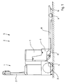
- FIG. 1 shows a pallet truck designed as an electric drawbar truck.
- the pallet truck has a drive part 1 with a drawbar 2, drive wheel 3 and support rollers 4.
- a battery receptacle device 6 is arranged on the load part 5 and contains an exchangeable battery box 7.
- the load part 5 is provided with load arms 8, each having a support roller 9 and a so-called climbing roller 10 at the right end in the figure.
- the load arms 8 are fastened in FIG. 1 in the manner known from the pallet trucks of the prior art.
- short fork tines 11 are attached to the load part 5, which extend into the hollow profile of the load arms 8 and are firmly connected to the latter.
- the linkage for extending the support roller 9 is arranged vertically below and thus for lifting the load arms 8.
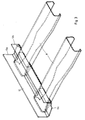
- FIGS. 2 and 3 The attachment of the load arms 8 according to the invention is shown in FIGS. 2 and 3.
- an essentially U-shaped profile 12 is provided, which is arranged transversely to the longitudinal axis of the vehicle, preferably below the battery receiving device 6, and is fixedly connected to it or formed on it (not shown in FIGS. 2 and 3).
- the U-profile 12 is provided on the webs 12a and 12b and on the belt 12c connecting the webs 12a and 12b with recesses for receiving the load arms 8.
- the load arms 8 thus extend into the U-profile 12.
- the load arms 8 are welded to the webs 12a and 12b and the belt 12c in the area of the penetration lines.
Landscapes
- Engineering & Computer Science (AREA)
- Chemical & Material Sciences (AREA)
- Combustion & Propulsion (AREA)
- Transportation (AREA)
- Mechanical Engineering (AREA)
- Forklifts And Lifting Vehicles (AREA)
- Handcart (AREA)
Description
Die Erfindung betrifft einen Gabelhubwagen mit einem Antriebsteil und einem anhebbaren Lastteil, der auf Tragrollen abgestützte Lastarme aufweist. Derartige Gabelhubwagen werden zum Beispiel als Niederhubwagen oder Kommissionierer in Geh-, Sitz- oder Standausführung eingesetzt. Oft sind diese Geräte deichsel gelenkt.The invention relates to a pallet truck with a drive part and a liftable load part, which has load arms supported on support rollers. Pallet trucks of this type are used, for example, as pallet trucks or order pickers in walking, sitting or standing versions. These devices are often steered.
Bei einem bekannten Gabelhubwagen sind die Lastarme, die im Querschnitt gesehen, ein Hohlprofil zur Aufnahme des Hubgestänges aufweisen, über kurze Gabelzinken geschoben. Die in die Lastarme hineinragenden Gabelzinken sind mit dem Lastteil des Gabelhubwagens verbunden, beispielsweise verschweißt. Es hat sich herausgestellt, daß diese Art der Befestigung der Lastarme am Lastteil im Hinblick auf den Herstellungs- und Montageaufwand verbesserungsbedürftig ist. Darüber hinaus kommt es bei einer derartigen Konstruktion zu Dauerfestigkeitsproblemen. Da die Lastarme durch die zu transportierende Last immer wieder elastisch verformt werden, kommt es vermehrt in demjenigen Bereich der Lastarme, in dem die eingeschobenen Gabelzinken enden, zu Brüchen. Die Ursache hierfür ist in dem relativ scharfkantigen Übergang vom Gabelzinken zum Lastarm zu sehen, wobei an dieser Stelle zugleich eine starke Verringerung des für die Festigkeit maßgeblichen Materialquerschnitts erfolgt. Dies führt dort zu einem ungünstigen Kraftfluß und damit zu Spannungsspitzen in den Lastarmen, was zu Ermüdungsbrüchen führt.In a known pallet truck, the load arms, seen in cross section, have a hollow profile for receiving the lifting rod, are pushed over short fork tines. The fork tines protruding into the load arms are connected, for example welded, to the load part of the pallet truck. It has been found that this type of attachment of the load arms to the load part is in need of improvement with regard to the manufacturing and assembly costs. In addition, fatigue problems arise with such a construction. Since the load arms are repeatedly elastically deformed by the load to be transported, breaks occur increasingly in the area of the load arms in which the inserted fork tines end. The reason for this is in the relatively sharp-edged transition from forks to the load arm can be seen, at which point there is at the same time a sharp reduction in the material cross section which is decisive for the strength. This leads to an unfavorable flow of force and thus to voltage peaks in the load arms, which leads to fatigue fractures.
DE-A-1 245 561 offenbart einen Hubwagen gemäß den Oberbegriff des Anspruchs 1.DE-A-1 245 561 discloses a pallet truck according to the preamble of claim 1.
Der vorliegenden Erfindung liegt die Aufgabe zugrunde, einen Gabelhubwagen der eingangs genannten Art zur Verfügung zu stellen, der eine verbesserte Befestigung der Lastarme aufweist.The present invention has for its object to provide a pallet truck of the type mentioned, which has an improved attachment of the load arms.
Diese Aufgabe wird erfindungsgemäß dadurch gelöst, daß die Lastarme an einem quer zur Fahrzeuglängsachse angeordneten, im Vertikalschnitt durch den Gabelhubwagen gesehen, im wesentlichen U-förmigen Profil des Lastteils befestigt sind, wobei die Stege und der die Stege verbindende Gurt des U-Profils jeweils an der zur Befestigung eines Lastarm vorgesehenen Stelle des U-Profils zur Aufnahme des Lastarms durchbrochen sind. Auf diese Weise werden die bisher zur Befestigung der Lastarme erforderlichen kurzen Gabelzinken überflüssig, wodurch sich der Herstellungs- und Montageaufwand verringert. Eine die Dauerfestigkeit verringernde Knickstelle, wie sie bei den Gabelhubwagen des Standes der Technik durch den in das Hohlprofil des Lastarms eingeschobenen Gabelzinken an dessen Ende gebildet wurde, ist nicht mehr vorhanden. Die direkt am Lastteil befestigten Lastarme haben darüber hinaus eine auf der gesamten Länge gleichbleibende Materialstärke. Die besondere Art und Weise der Befestigung der Lastarme mit Hilfe eines U-Profils ermöglicht einen guten Kraftfluß.This object is achieved in that the load arms are attached to a transversely to the longitudinal axis of the vehicle, seen in vertical section through the pallet truck, substantially U-shaped profile of the load part, the webs and the strap connecting the webs of the U-profile each the location of the U-profile intended to attach a load arm for receiving the load arm is broken. In this way, the short fork tines previously required for fastening the load arms are superfluous, as a result of which the manufacturing and assembly costs are reduced. A kink that reduces the fatigue strength, as was formed in the fork-lift trucks of the prior art by the fork tines inserted into the hollow profile of the load arm, is no longer present. The load arms attached directly to the load section also have a material thickness that remains the same over the entire length. The special way of attaching the load arms with the help of a U-profile enables a good flow of force.
Eine besonders vorteilhafte Befestigung der Lastarme ergibt sich dann, wenn die Lastarme im Bereich der Durchdringungslinien zum U-Profil mit dessen Stegen und dessen Gurt verschweißt sind. Es können dabei innerhalb oder außerhalb des U-Profils oder auch beidseitig Schweißnähte angebracht werden.A particularly advantageous fastening of the load arms results when the load arms are welded to the webs and the belt thereof in the area of the penetration lines to the U-profile. Welding seams can be made inside or outside the U-profile or on both sides.
Bei einem Gabelhubwagen, der batterie-elektrisch betrieben ist und bei dem auf dem Lastteil eine Batterieaufnahmevorrichtung angeordnet ist, erweist es sich als zweckmäßig, das U-Profil an der Batterieaufnahmevorrichtung zu befestigen oder an dieser zu bilden. Beispielsweise kann der Boden der Batterieaufnahmevorrichtung bereits bei der Herstellung entsprechend geformt werden.In a pallet truck that is battery-operated and in which a battery receptacle is arranged on the load part, it proves to be expedient to attach the U-profile to the battery receptacle or to form it. For example, the bottom of the battery receiving device can be shaped accordingly during manufacture.
Weitere Vorteile und Einzelheiten der Erfindung werden anhand eines in den Figuren schematisch dargestellten Ausführungsbeispieles näher erläutert. Dabei zeigt:
- Figur 1
- eine Seitenansicht eines Gabelhubwagens;
Figur 2- eine perspektivische Darstellung der erfindungsgemäßen Befestigung der Lastarme des Gabelhubwagens;
Figur 3- eine Darstellung nach
Figur 2 einschließlich der verdeckten Kanten.
- Figure 1
- a side view of a pallet truck;
- Figure 2
- a perspective view of the attachment of the load arms of the pallet truck according to the invention;
- Figure 3
- a representation of Figure 2 including the hidden edges.
In Figur 1 ist ein als Elektro-Deichsel-Hubwagen ausgebildeter Gabelhubwagen dargestellt. Der Gabelhubwagen weist einen Antriebsteil 1 mit Deichsel 2, Antriebsrad 3 und Stützrollen 4 auf. Mit dem Antriebsteil 1 gelenkig verbunden ist ein Lastteil 5, der über einen nicht dargestellten Hubmechanismus anhebbar ist. Auf dem Lastteil 5 ist eine Batterieaufnahmevorrichtung 6 angeordnet, in der sich eine austauschbare Batteriebox 7 befindet. Das Lastteil 5 ist mit Lastarmen 8 versehen, die jeweils am in der Figur rechten Ende eine Tragrolle 9 und eine sogenannte Kletterrolle 10 aufweisen. Die Lastarme 8 sind in Figur 1 auf die bei den Gabelhubwagen des Standes der Technik bekannte Weise befestigt. Hierzu sind kurze Gabelzinken 11 am Lastteil 5 befestigt, die sich in das Hohlprofil der Lastarme 8 hinein erstrecken und mit diesem fest verbunden sind. Im Innern des Hohlprofils ist das Gestänge zum Ausfahren der Tragrolle 9 nach vertikal unten und damit zum Anheben der Lastarme 8 angeordnet.FIG. 1 shows a pallet truck designed as an electric drawbar truck. The pallet truck has a drive part 1 with a
In den Figuren 2 und 3 ist die erfindungsgemäße Befestigung der Lastarme 8 gezeigt. Hierzu ist ein im wesentlichen U-förmiges Profil 12 vorgesehen, das quer zur Fahrzeuglängsachse, vorzugsweise unterhalb der Batterieaufnahmevorrichtung 6, angeordnet und mit dieser fest verbunden oder daran gebildet ist (in den Figuren 2 und 3 nicht dargestellt). Das U- Profil 12 ist an den Stegen 12a und 12b sowie an dem die Stege 12a und 12b verbindenden Gurt 12c mit Ausnehmungen zur Aufnahme der Lastarme 8 versehen. Die Lastarme 8 erstrecken sich also in das U-Profil 12 hinein. Die Lastarme 8 sind im Bereich der Durchdringungslinien mit den Stegen 12a und 12b und dem Gurt 12c verschweißt.The attachment of the
Claims (3)
- Fork-lift truck with a driving part and a load part which can be raised and which exhibits load arms supported on supporting rollers, characterised in that the load arms (8) are fixed to a profiled section (12) of the load part (1) which is of essentially U-shape viewed in the vertical section through the fork-lift truck and disposed at right angles to the longitudinal axis of the vehicle, the limbs (12a, 12b) and the chord (12c) connecting the limbs (12a, 12b) of the U-shaped profiled section (12) being in each case cut away to receive the load arm (8) at the location of the U-shaped profiled section (12) intended for fixture of a load arm (8).
- Fork-lift truck according to claim 1, characterised in that in the area of the cut lines the load arms (8) are welded to the U-shaped profiled section (12) by its limbs (12a, 12b) and its chord (12c).
- Fork-lift truck according to claim 1 or 2, the fork-lift truck being operated by electric battery and a battery holding device being disposed on the load part, characterised in that the U-shaped profiled section (12) is fixed to the battery holding device (6) or formed on the latter.
Applications Claiming Priority (2)
| Application Number | Priority Date | Filing Date | Title |
|---|---|---|---|
| DE4209861 | 1992-03-26 | ||
| DE4209861A DE4209861A1 (en) | 1992-03-26 | 1992-03-26 | Pallet truck |
Publications (2)
| Publication Number | Publication Date |
|---|---|
| EP0562482A1 EP0562482A1 (en) | 1993-09-29 |
| EP0562482B1 true EP0562482B1 (en) | 1996-09-04 |
Family
ID=6455091
Family Applications (1)
| Application Number | Title | Priority Date | Filing Date |
|---|---|---|---|
| EP93104536A Expired - Lifetime EP0562482B1 (en) | 1992-03-26 | 1993-03-19 | Fork lift truck |
Country Status (2)
| Country | Link |
|---|---|
| EP (1) | EP0562482B1 (en) |
| DE (2) | DE4209861A1 (en) |
Cited By (1)
| Publication number | Priority date | Publication date | Assignee | Title |
|---|---|---|---|---|
| US11840437B1 (en) | 2022-07-05 | 2023-12-12 | Tata Consultancy Services Limited | Fork assembly for autonomous mobile robots and automated guided vehicles |
Families Citing this family (5)
| Publication number | Priority date | Publication date | Assignee | Title |
|---|---|---|---|---|
| DE102006039758A1 (en) * | 2006-08-24 | 2008-02-28 | Jungheinrich Ag | Load arm for a pallet truck |
| DE102009056419B4 (en) | 2009-12-01 | 2022-01-20 | Jungheinrich Aktiengesellschaft | Load part for an industrial truck |
| CN103787237B (en) * | 2014-02-18 | 2015-10-14 | 中国人民解放军军事交通学院 | Hand-hydraulic storing cycle displacement dolly |
| US11235963B2 (en) | 2018-11-21 | 2022-02-01 | Hyster-Yale Group, Inc. | Forks for industrial vehicles and method of making same |
| DE102021121224A1 (en) | 2021-08-16 | 2023-02-16 | Jungheinrich Aktiengesellschaft | Load unit for autonomously guided industrial truck |
Family Cites Families (3)
| Publication number | Priority date | Publication date | Assignee | Title |
|---|---|---|---|---|
| FR1366002A (en) * | 1965-05-14 | 1964-07-10 | Lansing Bagnall Ltd | Improvements concerning industrial trucks |
| DE3710757A1 (en) * | 1987-03-31 | 1988-10-20 | Genkinger Hermann Gmbh | Pallet truck |
| US4969794A (en) * | 1989-09-29 | 1990-11-13 | Larsen Kurt K | Portable pallet truck |
-
1992
- 1992-03-26 DE DE4209861A patent/DE4209861A1/en not_active Withdrawn
-
1993
- 1993-03-19 DE DE59303611T patent/DE59303611D1/en not_active Expired - Fee Related
- 1993-03-19 EP EP93104536A patent/EP0562482B1/en not_active Expired - Lifetime
Cited By (1)
| Publication number | Priority date | Publication date | Assignee | Title |
|---|---|---|---|---|
| US11840437B1 (en) | 2022-07-05 | 2023-12-12 | Tata Consultancy Services Limited | Fork assembly for autonomous mobile robots and automated guided vehicles |
Also Published As
| Publication number | Publication date |
|---|---|
| EP0562482A1 (en) | 1993-09-29 |
| DE4209861A1 (en) | 1993-09-30 |
| DE59303611D1 (en) | 1996-10-10 |
Similar Documents
| Publication | Publication Date | Title |
|---|---|---|
| EP1878599B1 (en) | Stabiliser for linkage of a stabiliser rod on a motor vehicle | |
| DE4208700C2 (en) | Stem construction for vehicles | |
| EP1160106A2 (en) | Suspension arm for a vehicle | |
| EP1240065A1 (en) | Vehicle body comprising a bracing arrangement on the bottom side | |
| EP1057665A1 (en) | Axle suspension for rigid axles in vehicles | |
| EP2809531A1 (en) | Single-shell spring arm | |
| EP0562482B1 (en) | Fork lift truck | |
| EP2141035B1 (en) | Multi-point arm assembly for a vehicle frame of a commercial vehicle and container console and cross-member for a multi-point arm assembly | |
| DE2740948A1 (en) | Torsion rear axle for car - has trailing arms welded to axle on stress-relieved welds | |
| DE10054692B4 (en) | Beam axle | |
| DE2758764C2 (en) | Front wheel bearing block for a motor vehicle | |
| EP0373143B1 (en) | Tank, especially a fuel tank for motor vehicles | |
| EP3539802B1 (en) | Transverse arm with shell construction for a wheel suspension | |
| EP2766245B1 (en) | Subframe for motor vehicles | |
| EP1036728B1 (en) | Beam with longitudinal creases, especially for a motor vehicle roof | |
| DE2910210C2 (en) | Jack | |
| DE19618906B4 (en) | Climbing aid for a picking device | |
| DE3527184C1 (en) | Coil spring for the wheel suspension of a motor vehicle wheel suspension | |
| DE1630315A1 (en) | Safety structure for motor vehicles, especially passenger cars | |
| DE19742190B4 (en) | Pallet truck, in particular low-lift order picker | |
| DE102008009292A1 (en) | Reinforcing structure for longitudinal carrier of supporting frame in motor vehicle, has reinforcing element provided with predominant tubular cross-section and firmly connected with adjacent wall of components by material engagement | |
| EP1167172B1 (en) | Bicycle frame | |
| DE69801962T2 (en) | Front subframe for a motor vehicle | |
| EP3705386B1 (en) | Subframe | |
| DE3710573A1 (en) | Carrying device, for fork lift trucks in particular |
Legal Events
| Date | Code | Title | Description |
|---|---|---|---|
| PUAI | Public reference made under article 153(3) epc to a published international application that has entered the european phase |
Free format text: ORIGINAL CODE: 0009012 |
|
| 17P | Request for examination filed |
Effective date: 19930730 |
|
| AK | Designated contracting states |
Kind code of ref document: A1 Designated state(s): DE FR IT SE |
|
| GRAG | Despatch of communication of intention to grant |
Free format text: ORIGINAL CODE: EPIDOS AGRA |
|
| GRAH | Despatch of communication of intention to grant a patent |
Free format text: ORIGINAL CODE: EPIDOS IGRA |
|
| 17Q | First examination report despatched |
Effective date: 19960221 |
|
| GRAH | Despatch of communication of intention to grant a patent |
Free format text: ORIGINAL CODE: EPIDOS IGRA |
|
| GRAA | (expected) grant |
Free format text: ORIGINAL CODE: 0009210 |
|
| AK | Designated contracting states |
Kind code of ref document: B1 Designated state(s): DE FR IT SE |
|
| PG25 | Lapsed in a contracting state [announced via postgrant information from national office to epo] |
Ref country code: IT Free format text: LAPSE BECAUSE OF FAILURE TO SUBMIT A TRANSLATION OF THE DESCRIPTION OR TO PAY THE FEE WITHIN THE PRESCRIBED TIME-LIMIT;WARNING: LAPSES OF ITALIAN PATENTS WITH EFFECTIVE DATE BEFORE 2007 MAY HAVE OCCURRED AT ANY TIME BEFORE 2007. THE CORRECT EFFECTIVE DATE MAY BE DIFFERENT FROM THE ONE RECORDED. Effective date: 19960904 |
|
| ET | Fr: translation filed | ||
| REF | Corresponds to: |
Ref document number: 59303611 Country of ref document: DE Date of ref document: 19961010 |
|
| PG25 | Lapsed in a contracting state [announced via postgrant information from national office to epo] |
Ref country code: SE Effective date: 19961204 |
|
| PLBE | No opposition filed within time limit |
Free format text: ORIGINAL CODE: 0009261 |
|
| STAA | Information on the status of an ep patent application or granted ep patent |
Free format text: STATUS: NO OPPOSITION FILED WITHIN TIME LIMIT |
|
| 26N | No opposition filed | ||
| PGFP | Annual fee paid to national office [announced via postgrant information from national office to epo] |
Ref country code: DE Payment date: 20080521 Year of fee payment: 16 |
|
| REG | Reference to a national code |
Ref country code: FR Ref legal event code: TP |
|
| REG | Reference to a national code |
Ref country code: FR Ref legal event code: CJ Ref country code: FR Ref legal event code: CA |
|
| PG25 | Lapsed in a contracting state [announced via postgrant information from national office to epo] |
Ref country code: DE Free format text: LAPSE BECAUSE OF NON-PAYMENT OF DUE FEES Effective date: 20091001 |
|
| PGFP | Annual fee paid to national office [announced via postgrant information from national office to epo] |
Ref country code: FR Payment date: 20110401 Year of fee payment: 19 |
|
| REG | Reference to a national code |
Ref country code: FR Ref legal event code: ST Effective date: 20121130 |
|
| PG25 | Lapsed in a contracting state [announced via postgrant information from national office to epo] |
Ref country code: FR Free format text: LAPSE BECAUSE OF NON-PAYMENT OF DUE FEES Effective date: 20120402 |
|
| REG | Reference to a national code |
Ref country code: DE Ref legal event code: R082 Ref document number: 59303611 Country of ref document: DE Representative=s name: PATENTSHIP PATENTANWALTSGESELLSCHAFT MBH, DE |
|
| REG | Reference to a national code |
Ref country code: DE Ref legal event code: R082 Ref document number: 59303611 Country of ref document: DE Representative=s name: PATENTSHIP PATENTANWALTSGESELLSCHAFT MBH, DE |